EP3501723B1 - Dispositif d'usinage au laser destiné à usiner des pièces à usiner à l'aide du laser - Google Patents
Dispositif d'usinage au laser destiné à usiner des pièces à usiner à l'aide du laser Download PDFInfo
- Publication number
- EP3501723B1 EP3501723B1 EP18206367.7A EP18206367A EP3501723B1 EP 3501723 B1 EP3501723 B1 EP 3501723B1 EP 18206367 A EP18206367 A EP 18206367A EP 3501723 B1 EP3501723 B1 EP 3501723B1
- Authority
- EP
- European Patent Office
- Prior art keywords
- supply air
- workpiece support
- duct
- air duct
- flow direction
- Prior art date
- Legal status (The legal status is an assumption and is not a legal conclusion. Google has not performed a legal analysis and makes no representation as to the accuracy of the status listed.)
- Active
Links
Images

Classifications
-
- B—PERFORMING OPERATIONS; TRANSPORTING
- B23—MACHINE TOOLS; METAL-WORKING NOT OTHERWISE PROVIDED FOR
- B23Q—DETAILS, COMPONENTS, OR ACCESSORIES FOR MACHINE TOOLS, e.g. ARRANGEMENTS FOR COPYING OR CONTROLLING; MACHINE TOOLS IN GENERAL CHARACTERISED BY THE CONSTRUCTION OF PARTICULAR DETAILS OR COMPONENTS; COMBINATIONS OR ASSOCIATIONS OF METAL-WORKING MACHINES, NOT DIRECTED TO A PARTICULAR RESULT
- B23Q11/00—Accessories fitted to machine tools for keeping tools or parts of the machine in good working condition or for cooling work; Safety devices specially combined with or arranged in, or specially adapted for use in connection with, machine tools
- B23Q11/0042—Devices for removing chips
- B23Q11/006—Devices for removing chips by sucking and blowing simultaneously
-
- B—PERFORMING OPERATIONS; TRANSPORTING
- B23—MACHINE TOOLS; METAL-WORKING NOT OTHERWISE PROVIDED FOR
- B23K—SOLDERING OR UNSOLDERING; WELDING; CLADDING OR PLATING BY SOLDERING OR WELDING; CUTTING BY APPLYING HEAT LOCALLY, e.g. FLAME CUTTING; WORKING BY LASER BEAM
- B23K26/00—Working by laser beam, e.g. welding, cutting or boring
- B23K26/14—Working by laser beam, e.g. welding, cutting or boring using a fluid stream, e.g. a jet of gas, in conjunction with the laser beam; Nozzles therefor
- B23K26/1435—Working by laser beam, e.g. welding, cutting or boring using a fluid stream, e.g. a jet of gas, in conjunction with the laser beam; Nozzles therefor involving specially adapted flow-control means
- B23K26/1438—Working by laser beam, e.g. welding, cutting or boring using a fluid stream, e.g. a jet of gas, in conjunction with the laser beam; Nozzles therefor involving specially adapted flow-control means for directional control
-
- B—PERFORMING OPERATIONS; TRANSPORTING
- B08—CLEANING
- B08B—CLEANING IN GENERAL; PREVENTION OF FOULING IN GENERAL
- B08B15/00—Preventing escape of dirt or fumes from the area where they are produced; Collecting or removing dirt or fumes from that area
-
- B—PERFORMING OPERATIONS; TRANSPORTING
- B08—CLEANING
- B08B—CLEANING IN GENERAL; PREVENTION OF FOULING IN GENERAL
- B08B15/00—Preventing escape of dirt or fumes from the area where they are produced; Collecting or removing dirt or fumes from that area
- B08B15/02—Preventing escape of dirt or fumes from the area where they are produced; Collecting or removing dirt or fumes from that area using chambers or hoods covering the area
-
- B—PERFORMING OPERATIONS; TRANSPORTING
- B23—MACHINE TOOLS; METAL-WORKING NOT OTHERWISE PROVIDED FOR
- B23K—SOLDERING OR UNSOLDERING; WELDING; CLADDING OR PLATING BY SOLDERING OR WELDING; CUTTING BY APPLYING HEAT LOCALLY, e.g. FLAME CUTTING; WORKING BY LASER BEAM
- B23K26/00—Working by laser beam, e.g. welding, cutting or boring
- B23K26/14—Working by laser beam, e.g. welding, cutting or boring using a fluid stream, e.g. a jet of gas, in conjunction with the laser beam; Nozzles therefor
- B23K26/1435—Working by laser beam, e.g. welding, cutting or boring using a fluid stream, e.g. a jet of gas, in conjunction with the laser beam; Nozzles therefor involving specially adapted flow-control means
- B23K26/1437—Working by laser beam, e.g. welding, cutting or boring using a fluid stream, e.g. a jet of gas, in conjunction with the laser beam; Nozzles therefor involving specially adapted flow-control means for flow-rate control
-
- B—PERFORMING OPERATIONS; TRANSPORTING
- B23—MACHINE TOOLS; METAL-WORKING NOT OTHERWISE PROVIDED FOR
- B23K—SOLDERING OR UNSOLDERING; WELDING; CLADDING OR PLATING BY SOLDERING OR WELDING; CUTTING BY APPLYING HEAT LOCALLY, e.g. FLAME CUTTING; WORKING BY LASER BEAM
- B23K26/00—Working by laser beam, e.g. welding, cutting or boring
- B23K26/16—Removal of by-products, e.g. particles or vapours produced during treatment of a workpiece
-
- B—PERFORMING OPERATIONS; TRANSPORTING
- B23—MACHINE TOOLS; METAL-WORKING NOT OTHERWISE PROVIDED FOR
- B23K—SOLDERING OR UNSOLDERING; WELDING; CLADDING OR PLATING BY SOLDERING OR WELDING; CUTTING BY APPLYING HEAT LOCALLY, e.g. FLAME CUTTING; WORKING BY LASER BEAM
- B23K26/00—Working by laser beam, e.g. welding, cutting or boring
- B23K26/36—Removing material
-
- B—PERFORMING OPERATIONS; TRANSPORTING
- B23—MACHINE TOOLS; METAL-WORKING NOT OTHERWISE PROVIDED FOR
- B23K—SOLDERING OR UNSOLDERING; WELDING; CLADDING OR PLATING BY SOLDERING OR WELDING; CUTTING BY APPLYING HEAT LOCALLY, e.g. FLAME CUTTING; WORKING BY LASER BEAM
- B23K26/00—Working by laser beam, e.g. welding, cutting or boring
- B23K26/70—Auxiliary operations or equipment
-
- B—PERFORMING OPERATIONS; TRANSPORTING
- B23—MACHINE TOOLS; METAL-WORKING NOT OTHERWISE PROVIDED FOR
- B23K—SOLDERING OR UNSOLDERING; WELDING; CLADDING OR PLATING BY SOLDERING OR WELDING; CUTTING BY APPLYING HEAT LOCALLY, e.g. FLAME CUTTING; WORKING BY LASER BEAM
- B23K26/00—Working by laser beam, e.g. welding, cutting or boring
- B23K26/70—Auxiliary operations or equipment
- B23K26/702—Auxiliary equipment
-
- B—PERFORMING OPERATIONS; TRANSPORTING
- B23—MACHINE TOOLS; METAL-WORKING NOT OTHERWISE PROVIDED FOR
- B23K—SOLDERING OR UNSOLDERING; WELDING; CLADDING OR PLATING BY SOLDERING OR WELDING; CUTTING BY APPLYING HEAT LOCALLY, e.g. FLAME CUTTING; WORKING BY LASER BEAM
- B23K37/00—Auxiliary devices or processes, not specially adapted for a procedure covered by only one of the other main groups of this subclass
- B23K37/04—Auxiliary devices or processes, not specially adapted for a procedure covered by only one of the other main groups of this subclass for holding or positioning work
-
- B—PERFORMING OPERATIONS; TRANSPORTING
- B23—MACHINE TOOLS; METAL-WORKING NOT OTHERWISE PROVIDED FOR
- B23K—SOLDERING OR UNSOLDERING; WELDING; CLADDING OR PLATING BY SOLDERING OR WELDING; CUTTING BY APPLYING HEAT LOCALLY, e.g. FLAME CUTTING; WORKING BY LASER BEAM
- B23K37/00—Auxiliary devices or processes, not specially adapted for a procedure covered by only one of the other main groups of this subclass
- B23K37/06—Auxiliary devices or processes, not specially adapted for a procedure covered by only one of the other main groups of this subclass for positioning the molten material, e.g. confining it to a desired area
Definitions
- gases and solid particles are emitted from the processing point of the laser beam serving as the processing tool. These emissions can be harmful to people and materials.
- a housing provided for a work space of a laser processing device prevents harmful emissions from spreading into the surroundings of the laser processing device during the ongoing processing; nevertheless, personnel can be exposed to emissions during activities to be carried out inside the housing outside of the main working hours.
- Solid particles emitted from the processing point of a laser beam can cause mechanical damage, damage to the electrical system and / or damage to the control of the machine equipment used for workpiece processing due to their abrasiveness, their electrical conductivity and / or their adhesive behavior.
- a generic laser processing device as it is from JP S63295090 A is known, has for this purpose an air-permeable workpiece support arranged inside a housing with a suction device, by means of which emissions, which arise during the laser processing of workpieces on the upper side of the workpiece support, through the workpiece support to its underside and then out of the housing the laser processing device are extracted.
- the object of the present invention is to enable processing-related emissions to be carried away from the processing point of a laser beam used for laser processing of workpieces with an increased effectiveness compared to the generic prior art.
- a supply air duct through which supply air flows towards the workpiece support is arranged and provided with built-in components, due to which air flowing into the supply air duct at a duct inlet remote from the workpiece supports the supply air duct at a workpiece support-side duct opening as a laminar orientation perpendicular to a main support plane of the workpiece support Supply air flow leaves.
- the duct mouth of the supply air duct on the workpiece support side is at a distance from the top of the workpiece support and covers the workpiece support at least partially, preferably completely.
- the flow cross-section of the supply air duct is divided into partial cross-sections and partial cross-sectional walls which delimit the partial cross-sections extend with a mutual wall spacing in the flow direction transverse to the flow direction of the supply air.
- the partial cross-sectional walls of the supply air duct run parallel to one another in the flow direction and thereby perpendicular to the main support plane of the workpiece support.
- a negative pressure generated by means of a conventional vacuum pump can be applied to the working space inside the housing of the laser machining device according to the invention.
- the laminar supply air flow which is generated by means of the supply air duct provided according to the invention and functioning as a rectifier, is distributed homogeneously over the surface of the workpiece support and is consequently able to effectively record emissions that are generated on the workpiece surface due to the processing.
- the laminar flow character remains regardless of the Record of machining-related emissions received. Due to its laminar and consequently turbulence-free character, the incoming air flow loaded with the absorbed emissions can reach the underside of the workpiece support as an exhaust air flow on the shortest path from the top of the workpiece support. An undefined distribution of exhaust air laden with emissions inside the housing is avoided.
- the exhaust air leaves the housing of the laser processing device.
- a processing unit for example an exhaust air filter.
- the supply air duct can have an undivided flow cross-section over a partial length extending from the duct inlet of the supply air duct in the flow direction of the supply air and provided as the inlet length (patent claim 2) and / or the mutual wall spacings of the partial cross-sectional walls of the supply air duct at the mouth end lengths of the partial cross-sectional walls can be dimensioned uniformly (patent claim 3) and / or the mutual wall spacings of the partial cross-sectional walls of the supply air duct at the inlet-side ends of the partial cross-sectional walls facing the duct inlet of the supply air duct, in particular to take into account changes in the flow rate of the supply air occurring over the flow cross-section of the supply air duct, can be measured non-uniformly (Claim 4) and / or can lead to the duct inlet of the supply air duct inlet-side ends of the partial cross-sectional walls and / or the mouth-side ends of the partial cross-section
- a further embodiment of the invention provides that the flow direction of the supply air changes between the duct inlet of the supply air duct and the duct mouth of the supply air duct in that the partial cross-sectional walls of the supply air duct form guide surfaces for the supply air flowing to the workpiece support, whereby the supply air flowing to the workpiece support can be steered by means of the partial cross-sectional walls, preferably at right angles, from the flow direction at the channel inlet into the flow direction at the channel mouth (claim 7).
- the partial cross-sectional walls of the supply air duct preferably run over a partial length on the inlet side in the horizontal direction and over a partial length on the mouth side adjoining the partial length on the inlet side in the direction of flow of the supply air in the vertical direction and downwards in the direction of the laminar supply air flow loading workpiece support.
- a partition arranged inside the housing and extending perpendicular to the main support plane of the workpiece support is provided for the work space, which is open to the workpiece support-side channel mouth of the supply air duct and the work space against one inside the housing the remaining space formed by the laser processing device.
- the separation of the work area restricts the spread of processing-related emissions inside the housing.
- the one to be managed with the laminar supply air flow The area inside the housing can be limited to the immediate vicinity of the workpiece support. The volume flow of supply air required for the removal of emissions from inside the housing can be minimized in this way.
- a machine body of a laser processing machine of the laser processing device is used to delimit the working space from the remaining space for the sake of simplicity, which is arranged inside the housing next to the workpiece support (claim 9).
- a particularly effective removal of emissions is ensured in the case of a further design of the laser processing device according to the invention, which is provided with a separate partition for the work space, in that the workpiece support-side channel opening of the supply air duct preferably completely covers a cross-section of the work space formed within the partition parallel to the main support plane of the workpiece support ( Claim 10).
- This feature of the invention ensures that the supply air flow emerging from the supply air duct to the workpiece support completely captures the emissions generated during workpiece machining.
- the laser processing device according to the invention according to patent claim 11 is characterized by good accessibility of the separated work area inside the housing, in the case of which the separation of the work space is open to an access side of the workpiece support provided laterally next to the workpiece support and the housing of the laser processing device is open on the access side of the Workpiece support has an access-side wall with a closable access opening.
- part of the workpiece support-side duct opening of the supply air duct in the perpendicular projection onto the support main plane of the workpiece support opposite the workpiece support with a Overhang protrudes parallel to the main support plane of the workpiece support and that supply air, which exits in the flow direction at the projection of the workpiece support-side duct mouth of the supply air duct, can be directed towards the top of the workpiece support by means of a guide surface arranged laterally next to the workpiece support (claim 12).
- the guide surface directs the supply air, which may be contaminated with emissions, as exhaust air from the area next to the workpiece support to the top of the workpiece support, from where the exhaust air coming from the side area together with the supply air that is directly released onto the upper side of the workpiece surface and which is polluted with emissions can be discharged.
- the protrusion of the workpiece support-side duct opening of the supply air duct with respect to the workpiece support projects towards an access side of the workpiece support provided laterally next to the workpiece support.
- the guide surface which at the protrusion of the duct mouth of the supply air duct on the workpiece support side, directs the supply air emerging in the flow direction towards the top of the workpiece support, is provided on the access side of the workpiece support, preferably on an access side wall of the housing of the laser processing device. In this way, the area inside the housing that is entered first by personnel during the non-productive times of workpiece processing, for example for loading and unloading the workpiece support, is effectively kept free of emissions.
- the guide surface on the access-side wall of the housing can form a tear-off edge, by means of which the supply air emerging from the supply air duct at its lateral projection is detached from the access-side wall of the housing.
- patent claim 14 is evidenced in addition to one of the A lower supply air channel is provided through which the secondary supply air can be directed by means of an air conveying device as a secondary supply air flow with an initial flow direction running parallel to the main support plane of the workpiece support onto a lower guide surface arranged laterally next to the workpiece support, by means of which the secondary supply air flow can be directed can be steered from the initial flow direction into a flow direction running perpendicular to the main support plane of the workpiece support towards the top of the workpiece support.
- the secondary supply air coming from the lower supply air duct areas to the side next to the workpiece support from the underside of the workpiece support are kept free of machining-related emissions.
- the secondary supply air flow moving perpendicular to the main plane of the workpiece support is deflected once more by means of a guide surface and directed towards the top of the workpiece support, where it merges with the supply air flow coming from the upper supply air duct to remove emissions from the top the workpiece support can unite.
- the lower guide surface for the secondary supply air flow is provided on the housing of the laser processing device, preferably formed from the housing of the laser processing device (claim 15).
- the lower supply air duct is advantageously used to keep the access side of the workpiece support and thus the area in the interior of the housing of the laser processing device free of emissions.
- the features of the invention of claim 16 are preferably implemented jointly with the features of the invention of claim 12. On the resulting laser processing device, the access area of the workpiece support in the interior of the housing is kept particularly effectively emission-free.
- the lower supply air duct is also designed to generate a laminar supply air flow.
- the features of the invention provided for this purpose correspond to the measures taken on the upper supply air duct and explained in detail above.
- Claim 19 relates to a design of the laser processing device according to the invention, in the case of which several air ducts of the above type are provided to generate the laminar supply air flow on the top of the workpiece support and / or to generate the secondary supply air flow on the underside of the workpiece support.
- the laser processing device according to the invention is preferably provided with two upper and two lower supply air ducts, the two upper supply air ducts as well as the two lower supply air ducts being arranged symmetrically with respect to a plane running perpendicular to the main plane of the workpiece support and each of the supply air ducts having partial cross-sectional walls with a parallel to the Has support main plane of the workpiece support running in the horizontal direction inlet-side partial length.
- the upper supply air ducts adjoin the horizontal inlet-side partial lengths of the partial cross-sectional walls, the mouth-side partial lengths of the partial cross-sectional walls, which run perpendicular to the main support plane of the workpiece support downwards in the direction of the workpiece support to which the laminar supply air flow is applied. Mouth-side partial lengths of the partial cross-sectional walls of the lower supply air ducts run perpendicular to the associated inlet-side partial lengths and, like the inlet-side partial lengths, parallel to the main support plane of the workpiece support.
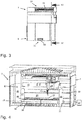
- a laser processing device 1 has a housing 2.
- a total of four access doors 4, each with a viewing window 5, are provided on an access side 3 of the housing 2.
- a first air supply channel 6, which forms a first upper air supply channel as part of a roof-side assembly 7, and a first lower air supply channel 8, which is provided as part of a base assembly 9 of the laser processing device 1, can also be seen.
- Figure 3 shows the viewer from Figure 1 remote side of the laser processing device 1.
- the roof-side assembly 7 of the laser processing device 1 in addition to the in Figure 1 first (upper) air inlet duct 6, which can be seen in an indicative manner, has a second (upper) air inlet duct 10.
- the base assembly 9 of the laser processing device 1 is evidenced Figure 3 in addition to the first lower supply air duct 8, it is provided with a second lower supply air duct 11.
- the laser cutting machine 12 has a machine body 13 and a boom 14 which can be moved along the machine body 13 and at the end of which is remote from the machine body 13 a laser cutting head 15 is attached as a laser processing unit.
- the laser cutting head 15 can be moved horizontally along the boom 14 in the usual manner and can be advanced in the vertical direction.
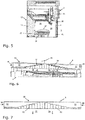
- a conventional workpiece support 16 is arranged in the interior of the housing 2 in front of the machine body 13 of the laser cutting machine 12.
- the workpiece support 16 supports a three-dimensional workpiece 17 to be processed by means of the laser cutting machine 12 on its upper side.
- the workpiece support 16 has support strips 18, which run parallel to one another at a mutual distance and which are in Figure 4 Form the main support plane 19 indicated by dash-dotted lines.
- the workpiece support 16 is air-permeable perpendicular to the main support plane 19.
- a box-like substructure 20 of the workpiece support 16 are located in Figure 4 concealed suction openings that connect to an in Figure 4 partially shown suction line 21 are connected.
- the section indicated by dashed lines extends the suction line 21 through a lateral opening of the housing 2 to an in Figure 4 also only indicated and serving as an air delivery device vacuum pump 22.
- a partition 23 divides the interior of the housing 2 into a working space 24 located inside the partition 23 and a remaining space 25 located outside the partition 23.
- the part of the partition 23 that faces the rear of the housing 2 is formed by the machine body 13 of the laser cutting machine 12.
- Lateral wall plates 26, 27 are provided as side parts of the partition 23.
- Evidence Figure 5 The side wall plate 26 extends from the machine body 13 of the laser cutting machine 12 to an access-side wall 28 of the housing 2.
- the side wall plate 27 of the partition 23 is dimensioned accordingly.
- the access-side wall 28 of the housing 2 is provided with access openings, which by means of the in the Figures 1 and 2 Access doors 4 shown can be locked.
- the access side 3 of the housing 2 is at the same time the access side of the workpiece support 16.
- the working space 24 is delimited by the wall 28 of the housing 2 on the access side.
- the work space 24 is accessible from the access side 3.
- the laser processing device 1 has the two (upper) supply air channels 6, 10 of the roof-side assembly 7 and the two lower supply air channels 8, 11 of the floor-side assembly 9.
- the working space 24 is accordingly designed as a flow box that is permanently open at the top and can be opened and closed on one side.
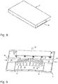
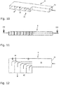
- the (upper) supply air ducts 6, 10 are in detail in the Figures 6 to 8 shown. Structural details of the lower air supply ducts 8, 11 emerge from the Figures 9 to 12 .
- the two lower air supply ducts 8, 11 are also located in relation to a main plane 19 of the workpiece support 16 running perpendicular to the support plane Figures 6 and 9
- the plane 29 indicated by dash-dotted lines is arranged symmetrically.
- supply air is supplied to the working space 24 of the laser processing device 1 due to a negative pressure applied to the working space 24 when the vacuum pump 22 is operating.
- the supply air flows at the (upper) supply air channels 6, 10 and at the lower supply air channels 8, 11 are in the Figures 6, 7 and 9, 10 indicated by arrows.
- Each of the (upper) supply air ducts 6, 10 has a duct inlet 30 remote from the workpiece support and a duct opening 31 on the workpiece support side.
- the duct openings 31 of the (upper) air supply ducts 6, 11 located upstream of the workpiece support 16 are spaced from the top of the workpiece support 16 and are also arranged above the laser cutting machine 12 of the laser processing device 1.
- the flow cross-section of the (upper) supply air channels 6, 10 is divided into partial cross-sections over a partial length of the (upper) supply air channels 6, 10 by partial cross-sectional walls 32.
- the partial cross-sectional walls 32 are rectangular in the example shown and form correspondingly running guide surfaces for the supply air conveyed by means of the vacuum pump 22.
- the optimal geometry of the partial cross-sectional walls also depends on the supply air volume and the available installation space; alternatively, e.g. rounded partial cross-sectional walls possible.
- the (upper) supply air channels 6, 10 have an undivided flow cross-section over a further partial length 33, which extends from the channel inlet 30 in the flow direction of the supply air and is provided as the inlet length. In the partial length 33 with an undivided flow cross section, the supply air flowing into the (upper) supply air ducts 6, 10 can already be made laminar.
- the partial cross-sectional walls 32 run parallel to one another and perpendicular to the main support plane 19 of the workpiece support 16.
- the mutual wall spacings of the partial cross-sectional walls 32 of the (upper) supply air ducts 6, 10 are uniform at the mouth-side end lengths of the partial cross-sectional walls 32 and at the duct inlet 30 facing inlet-side ends of the partial cross-sectional walls 32 are dimensioned non-uniformly.
- the partial cross-sectional walls 32 at the inlet-side ends facing the channel inlet 30 are offset from one another in the flow direction of the supply air, while the mouth-side ends of the partial cross-sectional walls 32 at the channel mouth 31 lie in a common plane running parallel to the main support plane 19 of the workpiece support 16.
- a grid-like screen 34 can be inserted into the duct inlet 30 of the (upper) supply air ducts 6, 10, as shown in FIG Figure 3 is shown at the duct inlet 30 of the (upper) supply air duct 10.
- the latter Due to the described configuration of the (upper) supply air ducts 6, 10, the latter generate a laminar supply air flow which, starting from the duct openings 31 of the (upper) supply air ducts 6, 10, is directed downwards in the figures with a flow direction perpendicular to the main support plane 19 of the workpiece support 16 is.
- the duct openings 31 of the two (upper) supply air ducts 6, 10 jointly completely cover the cross section of the working space 24 of the laser processing device 1 delimited by the partition 23.
- Evidence Figure 5 a part of the duct openings 31 of the (upper) air supply ducts 6, 10 protrudes in the vertical projection onto the main support plane 19 of the workpiece support 16 opposite the workpiece support 16 with a protrusion from the workpiece support 16.
- Supply air which exits at the area of the duct openings 31 of the (upper) supply air ducts 6, 10 arranged above the workpiece support 16, reaches the top of the workpiece support 16 as a laminar supply air flow, the supply air flow being homogeneous over the top of the workpiece support 16 due to its laminar character distributed.
- the supply air exiting is controlled by a guide plate 35 (which is arranged on the access side 3 next to the workpiece support 16 and forms a guide surface).
- Figure 5 steered towards the top of the workpiece support 16.
- secondary supply air is generated through the lower supply air ducts 8, 11 as a secondary supply air flow with an initial flow direction running parallel to the main support plane 19 of the workpiece support 16 abandoned in the working space 24 of the laser processing device 1.
- the secondary supply air is also conveyed by the negative pressure applied to the working space 24 by means of the vacuum pump 22.
- Each of the lower supply air ducts 8, 11 has a duct inlet 36 and a duct opening 37.
- the two duct openings 37 of the lower supply air ducts 8, 11 extend over the entire width of the workpiece support 16 or of the work space 24.
- Partial cross-sectional walls 38 divide the flow cross-section of the lower supply air channels 8, 11 over a partial length of the lower supply air channels 8, 11 into partial cross-sections and form guide surfaces for the supply air flowing from the channel inlet 36 to the channel mouth 37.
- the supply air flow is deflected at a right angle.
- the lower supply air ducts 8, 11 for the laminar expression of the secondary supply air flowing into the lower supply air ducts 8, 11 have a partial length 39 with an undivided flow cross-section that runs in the direction of flow of the secondary supply air and is provided as the inlet length.
- the mutual wall spacings of the partial cross-sectional walls 38 are non-uniform on the partial lengths of the partial cross-sectional walls 38 facing the channel inlet 36, and are uniformly dimensioned on the partial lengths of the partial cross-sectional walls 38 facing the channel mouth 37.
- the inlet-side ends of the partial cross-sectional walls 38 lie in a common plane running perpendicular to the flow direction of the secondary supply air. Mouth-side ends of the partial cross-sectional walls 38 are offset from one another in the direction of flow of the secondary supply air.
- the duct inlet 36 of the lower supply air ducts 8, 11 can be provided with a grid-like screen 40.
- a grid-like screen 40 on the duct inlet 36 of the lower supply air duct 11 is shown in FIG Figure 3 shown.
- the secondary supply air emerging at the duct openings 37 from the lower supply air ducts 8, 11 parallel to the main support plane 19 of the workpiece support 16 as a laminar secondary supply air flow arrives at a lower guide surface 41, which is formed by the access-side wall 28 of the housing 2 of the laser processing device 1 ( Figure 5 ).
- the initially horizontal secondary supply air flow is directed vertically upwards through the lower guide surface 41.
- There the secondary supply air flow meets the supply air flow originating from the two (upper) supply air ducts 6, 10 and directed by means of the guide plate 35 in the direction of the upper side of the workpiece support 16.
- the upper supply air flow and the lower supply air flow move as a combined supply air flow to the top of the workpiece support 16, where, together with the supply air flow directed perpendicularly from the (upper) supply air ducts 6, 10 onto the workpiece support 16, it absorbs machining-related emissions directly at the place of their origin.
- the vacuum pump 22 By means of the vacuum pump 22, the supply air laden with emissions is sucked off as exhaust air over the shortest route through the workpiece support 16.
- the supply air flow released through the (upper) supply air ducts 6, 10 into the interior of the housing 2 of the laser processing device 1 is provided as the main flow, the secondary supply air flow supplied to the interior of the housing 2 via the lower supply air ducts 8, 11 as a secondary flow.
- the volume flows of the main and secondary flow are matched to one another. In practice, a volume flow ratio main flow: secondary flow of 86%: 14% has proven itself. However, the optimal ratio depends on geometrical influencing variables of the housing 2, in particular the size of the working space 24 but also, for example, the distance between the lower guide surface 41 and the workpiece support 16. An advantageous volume flow ratio within the meaning of the invention will usually have a higher main flow than secondary flow .
- an optimal ratio is in the range of 95: 5 to 75:25.
- the optimum volume flow ratio can also be dependent on the size and geometry of the workpiece 17.
- the volume flow ratio is adjustable for example, via pressure losses that can be generated by means of the grid-like screens 34 on the (upper) supply air channels 6, 10 and by means of the grid-like screens 40 on the (lower) supply air channels 8, 11.
- fans can be provided on the supply air ducts 6, 8, 10, 11 for conveying the supply air; these can also enable the volume flow ratio to be set.
- processing-related emissions in the working space 24 of the laser processing device 1 are at least almost completely recorded and removed from the working space 24 by the shortest route.
- the area of the work space 24 located on the access side 3 of the housing 2 and the workpiece support 16 is intensively traversed by supply air and is thus kept free of machining-related emissions.
- Personnel who enter the work space 24 in the off-peak times of the laser processing, for example to load and unload the workpiece support 16 or to carry out maintenance and repair work, are consequently not exposed to any processing-related emissions.
Landscapes
- Engineering & Computer Science (AREA)
- Physics & Mathematics (AREA)
- Optics & Photonics (AREA)
- Mechanical Engineering (AREA)
- Plasma & Fusion (AREA)
- Fluid Mechanics (AREA)
- Laser Beam Processing (AREA)
Claims (19)
- Dispositif d'usinage au laser pour l'usinage de pièces (17) au moyen d'un laser, avec une unité d'usinage au laser (15), avec une enceinte (2), avec un espace de travail (24) prévu à l'intérieur de l'enceinte (2) et avec un dispositif de transport d'air (22),• dans lequel un support de pièce (16) pour une pièce (17) à usiner est disposé dans l'espace de travail (24) et le support de pièce (16) forme un plan principal de support (19) et est perméable à l'air perpendiculairement au plan principal de support (19),• dans lequel de l'air entrant peut être dirigé sur une face supérieure du support de pièce (16) au moyen du dispositif de transport d'air (22) avec une direction d'écoulement s'étendant perpendiculairement au plan principal de support (19) du support de pièce (16) et• dans lequel l'air entrant contaminé par suite de l'usinage peut être évacué au moyen du dispositif de transport d'air (22) en tant qu'air sortant de la face supérieure du support de pièce (16) à travers le support de pièce (16) vers la face inférieure du support de pièce (16) éloignée de la face supérieure du support de pièce (16),caractérisé en ce
qu'en amont du support de pièce (16), un conduit d'air entrant (6) par lequel l'air entrant s'écoule vers le support de pièce (16, 10) est prévu avec une section transversale d'écoulement formée perpendiculairement à la direction d'écoulement de l'air entrant ainsi qu'avec une entrée de conduit (30) éloignée du support de pièce et une sortie de conduit (31) côté support de pièce, espacée de la face supérieure du support de pièce (16) et recouvrant au moins partiellement le support de pièce (16), et
que, au moyen du conduit d'air entrant (6, 10), l'air entrant peut être dirigé sur la face supérieure du support de pièce (16) sous la forme d'un écoulement d'air entrant laminaire avec la direction d'écoulement s'étendant perpendiculairement au plan principal de support (19) du support de pièce (16), par le fait que la section transversale d'écoulement du conduit d'air entrant (6, 10) est divisée en sections transversales partielles et que des parois de sections transversales partielles (32), qui délimitent les sections transversales partielles, s'étendent dans la direction d'écoulement avec un espacement mutuel de parois existant transversalement à la direction d'écoulement de l'air entrant et sont orientées parallèlement entre elles et perpendiculairement au plan principal de support (19) du support de pièce (16) avec des longueurs terminales côté sortie s'étendant dans la direction d'écoulement et se terminant vers la sortie de conduit (31) du conduit d'air entrant (6, 10). - Dispositif d'usinage au laser selon la revendication 1, caractérisé en ce que le conduit d'air entrant (6, 10) présente une section transversale d'écoulement non divisée sur une longueur partielle (33) s'étendant à partir de l'entrée de conduit (30) du conduit d'air entrant (6, 10) dans la direction d'écoulement de l'air entrant et prévue comme longueur d'entrée.
- Dispositif d'usinage au laser selon l'une des revendications précédentes, caractérisé en ce que les espacements mutuels des parois de sections transversales partielles (32) du conduit d'air entrant (6, 10) sont dimensionnés de manière uniforme sur les longueurs terminales côté sortie des parois de sections transversales partielles (32).
- Dispositif d'usinage au laser selon l'une des revendications précédentes, caractérisé en ce que les espacements mutuels des parois de sections transversales partielles (32) du conduit d'air entrant (6, 10) sont dimensionnés de manière non uniforme aux extrémités côté entrée des parois de sections transversales partielles (32) qui sont orientées vers l'entrée de conduit (30) du conduit d'air entrant (6, 10).
- Dispositif d'usinage au laser selon l'une des revendications précédentes, caractérisé en ce que les extrémités côté entrée des parois de sections transversales partielles (32) orientées vers l'entrée de conduit (30) du conduit d'air entrant (6, 10) et/ou les extrémités côté sortie des parois de sections transversales partielles (32) orientées vers la sortie de conduit (31) du conduit d'air entrant (6, 10) sont décalées les unes par rapport aux autres dans la direction d'écoulement de l'air entrant.
- Dispositif d'usinage au laser selon l'une des revendications précédentes, caractérisé en ce que le conduit d'air entrant (6, 10) est pourvu, en amont des parois de sections transversales partielles (32), d'un diaphragme (34) par lequel l'air entrant passe dans la direction d'écoulement.
- Dispositif d'usinage au laser selon l'une des revendications précédentes, caractérisé en ce que la direction d'écoulement de l'air entrant change entre l'entrée de conduit (30) du conduit d'air entrant (6, 10) et la sortie de conduit (31) du conduit d'air entrant (6, 10), par le fait que les parois de sections transversales partielles (32) forment des surfaces de guidage pour l'air entrant s'écoulant vers le support de pièce (16), l'air entrant s'écoulant vers le support de pièce (16) pouvant être dévié au moyen des parois de sections transversales partielles (32), de préférence à angle droit, de la direction d'écoulement à l'entrée de conduit (30) dans la direction d'écoulement à la sortie de conduit (31).
- Dispositif d'usinage au laser selon l'une des revendications précédentes, caractérisé en ce qu'il est prévu pour l'espace de travail (24) une cloison (23) qui est disposée à l'intérieur de l'enceinte (2) et s'étend perpendiculairement au plan principal de support (19) du support de pièce (16), laquelle cloison est ouverte vers la sortie de conduit (31) du conduit d'air entrant (6, 10) et délimite l'espace de travail (23) par rapport à un espace restant (25) formé à l'intérieur de l'enceinte (2) du dispositif d'usinage au laser.
- Dispositif d'usinage au laser selon la revendication 8, caractérisé en ce que la cloison (23) de l'espace de travail (24) est formée en partie par un corps de machine (13) d'une machine d'usinage au laser (12) du dispositif d'usinage au laser, le corps de machine (13) étant disposé latéralement à côté du support de pièce (16) et la machine d'usinage au laser (12) étant prévue à l'intérieur de l'enceinte (2).
- Dispositif d'usinage au laser selon la revendication 8 ou la revendication 9, caractérisé en ce que la sortie de conduit (31) du conduit d'air entrant (6, 10) recouvre de préférence complètement une section transversale de la chambre de travail (24), la section transversale étant formée à l'intérieur de la cloison (23) parallèlement au plan principal de support (19) du support de pièce (16).
- Dispositif d'usinage au laser selon l'une des revendications 8 à 10, caractérisé en ce que la cloison (23) de la chambre de travail (24) est ouverte vers un côté d'accès (3) du support de pièce (16) prévu latéralement à côté du support de pièce (16) et que l'enceinte (2) du dispositif d'usinage au laser présente, sur le côté d'accès (3) du support de pièce (16), une paroi côté accès (28) avec une ouverture d'accès pouvant être fermée.
- Dispositif d'usinage au laser selon l'une des revendications précédentes, caractérisé en ce qu'une partie de la sortie de conduit (31) du conduit d'air entrant (6, 10) fait saillie en projection verticale sur le plan principal de support (19) du support de pièce (16) par rapport au support de pièce (16) avec un dépassement parallèle au plan principal de support (19) du support de pièce (16) et que l'air entrant, qui sort dans la direction d'écoulement au niveau du dépassement de la sortie de conduit (31) du conduit d'air entrant (6, 10), peut être dévié en direction de la face supérieure du support de pièce (16) au moyen d'une surface de guidage disposée latéralement à côté du support de pièce (16).
- Dispositif d'usinage au laser selon la revendication 12, caractérisé en ce que le dépassement de la sortie de conduit (31) du conduit d'air entrant (6, 10) fait saillie par rapport au support de pièce (16) vers un côté d'accès (3) du support de pièce (16) prévu latéralement à côté du support de pièce (16), et que la surface de guidage, au moyen de laquelle l'air entrant sortant dans la direction d'écoulement au niveau du dépassement de la sortie de conduit (31) du conduit d'air entrant (6, 10) peut être dévié vers la face supérieure du support de pièce (16), est prévue sur le côté d'accès (3) du support de pièce (16), de préférence sur une paroi côté accès (28) de l'enceinte (2) du dispositif d'usinage au laser.
- Dispositif d'usinage au laser selon l'une des revendications précédentes, caractérisé en ce que le conduit d'air entrant (6, 10) forme un conduit d'air entrant supérieur (6, 10) et qu'en plus du conduit d'air entrant supérieur (6, 10), un conduit d'air entrant inférieur (8, 11) est prévu à la face inférieure du support de pièce (16), par lequel de l'air entrant secondaire peut être dirigé au moyen d'un dispositif de transport d'air (22), sous la forme d'un écoulement d'air entrant secondaire avec une direction d'écoulement initiale s'étendant parallèlement au plan principal de support (19) du support de pièce (16), sur une surface de guidage inférieure (41) disposée latéralement à côté du support de pièce (16), au moyen de laquelle l'écoulement d'air entrant secondaire peut être dévié de la direction d'écoulement initiale dans une direction d'écoulement s'étendant perpendiculairement au plan principal de support (19) du support de pièce (16) vers la face supérieure du support de pièce (16).
- Dispositif d'usinage au laser selon la revendication 14, caractérisé en ce que la surface de guidage inférieure (41) pour l'écoulement d'air entrant secondaire est prévue sur l'enceinte (2) du dispositif d'usinage au laser, de préférence formée par l'enceinte (2) du dispositif d'usinage au laser.
- Dispositif d'usinage au laser selon la revendication 14 ou la revendication 15, caractérisé en ce que le support de pièce (16) présente un côté d'accès (3) prévu latéralement à côté du support de pièce (16) et que l'écoulement d'air entrant secondaire peut être dévié, sur le côté d'accès (3) du support de pièce (16), de la direction d'écoulement initiale dans la direction d'écoulement s'étendant perpendiculairement au plan principal de support (19) du support de pièce (16) vers la face supérieure du support de pièce (16).
- Dispositif d'usinage au laser selon l'une des revendications 14 à 16, caractérisé en ce que l'air entrant secondaire peut être dirigé au moyen du conduit d'air entrant inférieur (8, 11) sous la forme d'un écoulement d'air entrant secondaire laminaire avec la direction d'écoulement initiale sur la surface de guidage inférieure (41), en divisant la section transversale d'écoulement du conduit d'air entrant inférieur (8, 11) en sections transversales partielles et en parois de sections transversales partielles (38) qui limitent les sections transversales partielles, s'étendent dans la direction d'écoulement avec un espacement mutuel de parois existant transversalement à la direction d'écoulement de l'air entrant secondaire et sont orientées parallèlement entre elles dans la direction d'écoulement initiale de l'air entrant secondaire avec des longueurs terminales côté surface de guidage s'étendant dans la direction d'écoulement et se terminant vers une sortie de conduit (37) du conduit d'air entrant inférieur (8, 11).
- Dispositif d'usinage au laser selon la revendication 17, caractérisé en ce• que le conduit d'air entrant inférieur (8, 11) présente une section transversale d'écoulement non divisée sur une longueur partielle (39) s'étendant dans la direction d'écoulement de l'air entrant secondaire à partir d'une entrée de conduit (36) du conduit d'air entrant inférieur (8, 11) éloignée de la surface de guidage et prévue comme longueur d'entrée et/ou• que les espacements mutuels des parois de sections transversales partielles (38) du conduit d'air entrant inférieur (8, 11) sont dimensionnés de manière uniforme aux longueurs terminales des parois de sections transversales partielles (38) côté surface de guidage et/ou• que les espacements mutuels des parois de sections transversales partielles (38) du conduit d'air entrant inférieur (8, 11) sont dimensionnés de manière non uniforme aux extrémités côté entrée des parois de sections transversales partielle (38) qui sont orientées vers une entrée de conduit (36) du conduit d'air entrant inférieur (8, 11) éloignée de la surface de guidage et/ou• que des extrémités côté entrée des parois de sections transversales partielles (38) orientées vers une entrée de conduit (36) du conduit d'air entrant inférieur (8, 11) éloignée de la surface de guidage et/ou des extrémités côté sortie des parois de sections transversales partielles (38) orientées vers la sortie de conduit (37) du conduit d'air entrant inférieur (8, 11) sont décalées les unes par rapport aux autres dans la direction d'écoulement de l'air entrant secondaire et/ou• que le conduit d'air entrant inférieur (8, 11) est pourvu, en amont des parois de sections transversales partielles (38), d'un diaphragme (40) par lequel l'air entrant secondaire passe dans la direction d'écoulement et/ou• que la direction d'écoulement de l'air entrant secondaire change entre une entrée de conduit (36) du conduit d'air entrant inférieur (8, 11) éloignée de la surface de guidage et la sortie de conduit (37) du conduit d'air entrant inférieur (8, 11), par le fait que les parois de sections transversales partielles (38) du conduit d'air entrant inférieur (8, 11) forment des surfaces de guidage pour l'air entrant secondaire, l'air entrant secondaire pouvant être dévié au moyen des parois de sections transversales partielles (38) du conduit d'air entrant inférieur (8, 11) de préférence à angle droit de la direction d'écoulement à l'entrée de conduit (36) du conduit d'air entrant inférieur (8, 11) dans la direction d'écoulement initiale à la sortie de conduit (37) du conduit d'air entrant inférieur (8, 11).
- Dispositif d'usinage au laser selon l'une des revendications précédentes, caractérisé en ce que plusieurs conduits d'air entrant (6, 10), éventuellement plusieurs conduits d'air entrant supérieurs (6, 10), sont prévus, dont les sorties de conduit (31) sont disposées les unes à côté des autres parallèlement au plan principal de support (19) du support de pièce (16) et/ou que plusieurs conduits d'air entrant inférieurs (8, 11) sont prévus qui présentent des sorties de conduit (37) côté surface de guidage, qui sont disposées les unes à côté des autres parallèlement au plan principal de support (19) du support de pièce (16).
Applications Claiming Priority (1)
| Application Number | Priority Date | Filing Date | Title |
|---|---|---|---|
| DE102017129479.1A DE102017129479A1 (de) | 2017-12-11 | 2017-12-11 | Laserbearbeitungsvorrichtung zum Bearbeiten von Werkstücken mittels Laser |
Publications (2)
| Publication Number | Publication Date |
|---|---|
| EP3501723A1 EP3501723A1 (fr) | 2019-06-26 |
| EP3501723B1 true EP3501723B1 (fr) | 2020-09-09 |
Family
ID=64331699
Family Applications (1)
| Application Number | Title | Priority Date | Filing Date |
|---|---|---|---|
| EP18206367.7A Active EP3501723B1 (fr) | 2017-12-11 | 2018-11-15 | Dispositif d'usinage au laser destiné à usiner des pièces à usiner à l'aide du laser |
Country Status (6)
| Country | Link |
|---|---|
| US (1) | US11161212B2 (fr) |
| EP (1) | EP3501723B1 (fr) |
| KR (1) | KR102329564B1 (fr) |
| CN (1) | CN109909607B (fr) |
| DE (1) | DE102017129479A1 (fr) |
| ES (1) | ES2828047T3 (fr) |
Families Citing this family (8)
| Publication number | Priority date | Publication date | Assignee | Title |
|---|---|---|---|---|
| CN110405352B (zh) * | 2019-07-11 | 2021-07-23 | 大族激光科技产业集团股份有限公司 | 一种全自动双工位激光打标机 |
| DE102019126697B4 (de) * | 2019-10-02 | 2023-07-13 | Lpkf Laser & Electronics Ag | Vorrichtung zur Bearbeitung eines Substrats mittels eines Laserstrahls |
| WO2021237095A1 (fr) * | 2020-05-22 | 2021-11-25 | Bold Laser Automation, Inc. | Système sous vide à grande vitesse pour ablation au laser |
| CN112192023A (zh) * | 2020-09-21 | 2021-01-08 | 辛真真 | 一种激光切割机 |
| DE102020129413A1 (de) * | 2020-11-09 | 2022-05-12 | Trumpf Laser- Und Systemtechnik Gmbh | Verfahren und Vorrichtung zur Herstellung von dreidimensionalen Objekten durch selektives Verfestigen eines schichtweise aufgebrachten Aufbaumaterials |
| US12103104B2 (en) * | 2021-03-26 | 2024-10-01 | Mitsubishi Electric Corporation | Laser machine |
| CN114536082A (zh) * | 2022-03-03 | 2022-05-27 | 安徽双虎智能装备有限公司 | 一种金属加工用切削机床自清理机构及清理方法 |
| DE102023136276A1 (de) * | 2023-12-21 | 2025-06-26 | TRUMPF Laser- und Systemtechnik SE | Einströmkanal zum Homogenisieren eines Schutzgasflusses in einer additiven Fertigungsvorrichtung sowie eine Fertigungsvorrichtung |
Family Cites Families (20)
| Publication number | Priority date | Publication date | Assignee | Title |
|---|---|---|---|---|
| US3664253A (en) * | 1969-01-27 | 1972-05-23 | Gunnar C F Asker | Conditioned air distribution system |
| US3646253A (en) * | 1970-11-13 | 1972-02-29 | Gen Electric | Tint control for a color television receiver |
| JPS63295090A (ja) | 1987-05-26 | 1988-12-01 | Jido Hosei Syst Gijutsu Kenkyu Kumiai | レ−ザ加工装置用の煙除去装置 |
| DE69520700T2 (de) * | 1994-02-10 | 2001-08-09 | Michihiko Kawano | Rohrkrümmer mit Leitschaufeln |
| JP2948199B2 (ja) * | 1997-09-22 | 1999-09-13 | 通彦 川野 | 案内羽根入り吸込エルボ |
| JP3999933B2 (ja) * | 2000-10-16 | 2007-10-31 | 株式会社脇坂エンジニアリング | 集積製品の塵埃除去装置 |
| ATE444778T1 (de) * | 2006-09-07 | 2009-10-15 | Biotronik Crm Patent Ag | Zusammengesetztes fernfeld-elektrokardiogramm |
| CN201037151Y (zh) * | 2007-04-05 | 2008-03-19 | 武汉材料保护研究所 | 激光表面改性加工同轴气体保护送粉装置 |
| US20090299330A1 (en) * | 2008-04-28 | 2009-12-03 | Mac Iver Robroy H | Cellular Delivery Device |
| CN201324912Y (zh) * | 2008-11-19 | 2009-10-14 | 深圳市大族激光科技股份有限公司 | 一种非晶硅薄膜太阳能电池激光刻划设备 |
| JP5500914B2 (ja) * | 2009-08-27 | 2014-05-21 | 株式会社半導体エネルギー研究所 | レーザ照射装置 |
| CN101829848B (zh) * | 2010-01-29 | 2013-04-10 | 东莞晨真光伏有限公司 | 激光刻线除尘设备及除尘方法 |
| WO2013178281A1 (fr) * | 2012-06-01 | 2013-12-05 | Trumpf Werkzeugmaschinen Gmbh + Co. Kg | Machine de traitement thermique de pièces et procédé d'étouffement d'un incendie |
| DE102014205875A1 (de) * | 2014-03-28 | 2015-10-01 | Eos Gmbh Electro Optical Systems | Vorrichtung und Verfahren zum schichtweisen Herstellen eines dreidimensionalen Objekts |
| CN204603564U (zh) * | 2015-01-29 | 2015-09-02 | 广州市艾派克智能激光科技有限公司 | 一种激光加工烟尘环保处理装置 |
| CN104923924A (zh) * | 2015-06-05 | 2015-09-23 | 江苏塞维斯数控科技有限公司 | 一种除尘激光切割机 |
| US12491577B2 (en) * | 2016-01-12 | 2025-12-09 | Mestek Machinery, Inc. | Protection system for laser cutting machine |
| DE102016202043A1 (de) * | 2016-02-11 | 2017-08-17 | Robert Bosch Gmbh | Vorrichtung für eine Bearbeitungsanlage, insbesondere für eine Laserbearbeitungsanlage und Laserbearbeitungsanlage |
| EP3213859B1 (fr) * | 2016-03-01 | 2023-05-17 | Bystronic Laser AG | Machine de traitement au laser avec dispositif d'élimination des résidus |
| CN107202415B (zh) * | 2016-03-17 | 2019-07-19 | 倚世节能科技(上海)有限公司 | 一种稳流结构及应用该稳流结构的通风设备 |
-
2017
- 2017-12-11 DE DE102017129479.1A patent/DE102017129479A1/de not_active Withdrawn
-
2018
- 2018-11-15 EP EP18206367.7A patent/EP3501723B1/fr active Active
- 2018-11-15 ES ES18206367T patent/ES2828047T3/es active Active
- 2018-12-07 US US16/212,991 patent/US11161212B2/en active Active
- 2018-12-10 KR KR1020180158078A patent/KR102329564B1/ko active Active
- 2018-12-11 CN CN201811510732.XA patent/CN109909607B/zh active Active
Non-Patent Citations (1)
| Title |
|---|
| None * |
Also Published As
| Publication number | Publication date |
|---|---|
| ES2828047T3 (es) | 2021-05-25 |
| DE102017129479A1 (de) | 2019-06-13 |
| US20190176282A1 (en) | 2019-06-13 |
| CN109909607B (zh) | 2021-03-16 |
| CN109909607A (zh) | 2019-06-21 |
| US11161212B2 (en) | 2021-11-02 |
| EP3501723A1 (fr) | 2019-06-26 |
| KR102329564B1 (ko) | 2021-11-23 |
| KR20190069325A (ko) | 2019-06-19 |
Similar Documents
| Publication | Publication Date | Title |
|---|---|---|
| EP3501723A1 (fr) | Dispositif d'usinage au laser destiné à usiner des pièces à usiner à l'aide du laser | |
| EP1931480B1 (fr) | Dispositif et procede destines a separer la peinture humide perdue lors de la pulverisation | |
| DE102015008844A1 (de) | Vorrichtung zum Abscheiden von Overspray und Oberflächenbehandlungsanlage | |
| DE102016112652A1 (de) | Metall-3D-Drucker | |
| DE1752212A1 (de) | Anlage zum Beschichten von Gegenstaenden | |
| DE202016000049U1 (de) | Integriertes Werkstückpositionierungssystem mit integralem Dampfabzugssystem | |
| DE102013020820B4 (de) | Absaugvorrichtung und Werkzeugmaschine | |
| WO2007039275A1 (fr) | Dispositif et procede destines a separer la peinture humide perdue lors de la pulverisation | |
| DE102015010387A1 (de) | Additive Fertigung dreidimensionaler Strukturen | |
| EP4037840A1 (fr) | Système de traitement et procédé de traitement | |
| EP2244839B1 (fr) | Installation de peinture | |
| DE8228345U1 (de) | In eine arbeitskabine od.dgl. einsetzbare belueftungsverteilerwand | |
| DE3740201C2 (fr) | ||
| DE102019127751A1 (de) | Filtervorrichtung und Verfahren zum Abreinigen eines Filterelements einer Filtervorrichtung | |
| DE202010006045U1 (de) | Maschinelle Anlage zum thermischen Bearbeiten von Werkstücken | |
| WO2019052947A1 (fr) | Installation et procédé de revêtement d'objets | |
| DE4413600A1 (de) | Entsorgung von Luftschadstoffen | |
| DE102011122056A1 (de) | Anlage zum Beschichten von Gegenständen | |
| DE102015116646A1 (de) | Verfahren zum Be- und Entladen einer Maschine sowie Maschine zur trennenden Bearbeitung eines plattenförmigen metallischen Materials, insbesondere zur Durchführung des Verfahrens | |
| DE19822537A1 (de) | Reinigungsvorrichtung für Karosserien von Fahrzeugen | |
| AT506653B1 (de) | Vorrichtung zum bearbeiten von werkstücken | |
| DE3213642A1 (de) | Staubfiltervorrichtung | |
| DE10202945A1 (de) | Vorrichtung zur Vermeidung oder Minderung von luftgetragenen Emissionen an spanenden oder abtragenden Bearbeitungsmaschinen | |
| EP1895242A1 (fr) | Procédé et dispositif destinés à empêcher l'air chargé de sortir des pièces à l'aide d'un rideau d'air | |
| WO2000061308A1 (fr) | Cage de laminoir |
Legal Events
| Date | Code | Title | Description |
|---|---|---|---|
| PUAI | Public reference made under article 153(3) epc to a published international application that has entered the european phase |
Free format text: ORIGINAL CODE: 0009012 |
|
| STAA | Information on the status of an ep patent application or granted ep patent |
Free format text: STATUS: THE APPLICATION HAS BEEN PUBLISHED |
|
| AK | Designated contracting states |
Kind code of ref document: A1 Designated state(s): AL AT BE BG CH CY CZ DE DK EE ES FI FR GB GR HR HU IE IS IT LI LT LU LV MC MK MT NL NO PL PT RO RS SE SI SK SM TR |
|
| AX | Request for extension of the european patent |
Extension state: BA ME |
|
| STAA | Information on the status of an ep patent application or granted ep patent |
Free format text: STATUS: REQUEST FOR EXAMINATION WAS MADE |
|
| 17P | Request for examination filed |
Effective date: 20191220 |
|
| RBV | Designated contracting states (corrected) |
Designated state(s): AL AT BE BG CH CY CZ DE DK EE ES FI FR GB GR HR HU IE IS IT LI LT LU LV MC MK MT NL NO PL PT RO RS SE SI SK SM TR |
|
| GRAP | Despatch of communication of intention to grant a patent |
Free format text: ORIGINAL CODE: EPIDOSNIGR1 |
|
| STAA | Information on the status of an ep patent application or granted ep patent |
Free format text: STATUS: GRANT OF PATENT IS INTENDED |
|
| RIC1 | Information provided on ipc code assigned before grant |
Ipc: B08B 15/02 20060101ALI20200331BHEP Ipc: B23K 37/06 20060101ALI20200331BHEP Ipc: B23K 26/16 20060101AFI20200331BHEP Ipc: B08B 15/00 20060101ALI20200331BHEP Ipc: B23K 26/70 20140101ALI20200331BHEP |
|
| INTG | Intention to grant announced |
Effective date: 20200506 |
|
| GRAS | Grant fee paid |
Free format text: ORIGINAL CODE: EPIDOSNIGR3 |
|
| GRAA | (expected) grant |
Free format text: ORIGINAL CODE: 0009210 |
|
| STAA | Information on the status of an ep patent application or granted ep patent |
Free format text: STATUS: THE PATENT HAS BEEN GRANTED |
|
| AK | Designated contracting states |
Kind code of ref document: B1 Designated state(s): AL AT BE BG CH CY CZ DE DK EE ES FI FR GB GR HR HU IE IS IT LI LT LU LV MC MK MT NL NO PL PT RO RS SE SI SK SM TR |
|
| REG | Reference to a national code |
Ref country code: GB Ref legal event code: FG4D Free format text: NOT ENGLISH |
|
| REG | Reference to a national code |
Ref country code: AT Ref legal event code: REF Ref document number: 1310971 Country of ref document: AT Kind code of ref document: T Effective date: 20200915 Ref country code: CH Ref legal event code: EP |
|
| REG | Reference to a national code |
Ref country code: IE Ref legal event code: FG4D Free format text: LANGUAGE OF EP DOCUMENT: GERMAN |
|
| REG | Reference to a national code |
Ref country code: DE Ref legal event code: R096 Ref document number: 502018002390 Country of ref document: DE |
|
| REG | Reference to a national code |
Ref country code: LT Ref legal event code: MG4D |
|
| PG25 | Lapsed in a contracting state [announced via postgrant information from national office to epo] |
Ref country code: SE Free format text: LAPSE BECAUSE OF FAILURE TO SUBMIT A TRANSLATION OF THE DESCRIPTION OR TO PAY THE FEE WITHIN THE PRESCRIBED TIME-LIMIT Effective date: 20200909 Ref country code: HR Free format text: LAPSE BECAUSE OF FAILURE TO SUBMIT A TRANSLATION OF THE DESCRIPTION OR TO PAY THE FEE WITHIN THE PRESCRIBED TIME-LIMIT Effective date: 20200909 Ref country code: NO Free format text: LAPSE BECAUSE OF FAILURE TO SUBMIT A TRANSLATION OF THE DESCRIPTION OR TO PAY THE FEE WITHIN THE PRESCRIBED TIME-LIMIT Effective date: 20201209 Ref country code: LT Free format text: LAPSE BECAUSE OF FAILURE TO SUBMIT A TRANSLATION OF THE DESCRIPTION OR TO PAY THE FEE WITHIN THE PRESCRIBED TIME-LIMIT Effective date: 20200909 Ref country code: GR Free format text: LAPSE BECAUSE OF FAILURE TO SUBMIT A TRANSLATION OF THE DESCRIPTION OR TO PAY THE FEE WITHIN THE PRESCRIBED TIME-LIMIT Effective date: 20201210 Ref country code: BG Free format text: LAPSE BECAUSE OF FAILURE TO SUBMIT A TRANSLATION OF THE DESCRIPTION OR TO PAY THE FEE WITHIN THE PRESCRIBED TIME-LIMIT Effective date: 20201209 Ref country code: FI Free format text: LAPSE BECAUSE OF FAILURE TO SUBMIT A TRANSLATION OF THE DESCRIPTION OR TO PAY THE FEE WITHIN THE PRESCRIBED TIME-LIMIT Effective date: 20200909 |
|
| REG | Reference to a national code |
Ref country code: NL Ref legal event code: MP Effective date: 20200909 |
|
| PG25 | Lapsed in a contracting state [announced via postgrant information from national office to epo] |
Ref country code: LV Free format text: LAPSE BECAUSE OF FAILURE TO SUBMIT A TRANSLATION OF THE DESCRIPTION OR TO PAY THE FEE WITHIN THE PRESCRIBED TIME-LIMIT Effective date: 20200909 Ref country code: RS Free format text: LAPSE BECAUSE OF FAILURE TO SUBMIT A TRANSLATION OF THE DESCRIPTION OR TO PAY THE FEE WITHIN THE PRESCRIBED TIME-LIMIT Effective date: 20200909 Ref country code: PL Free format text: LAPSE BECAUSE OF FAILURE TO SUBMIT A TRANSLATION OF THE DESCRIPTION OR TO PAY THE FEE WITHIN THE PRESCRIBED TIME-LIMIT Effective date: 20200909 |
|
| PG25 | Lapsed in a contracting state [announced via postgrant information from national office to epo] |
Ref country code: SM Free format text: LAPSE BECAUSE OF FAILURE TO SUBMIT A TRANSLATION OF THE DESCRIPTION OR TO PAY THE FEE WITHIN THE PRESCRIBED TIME-LIMIT Effective date: 20200909 Ref country code: EE Free format text: LAPSE BECAUSE OF FAILURE TO SUBMIT A TRANSLATION OF THE DESCRIPTION OR TO PAY THE FEE WITHIN THE PRESCRIBED TIME-LIMIT Effective date: 20200909 Ref country code: RO Free format text: LAPSE BECAUSE OF FAILURE TO SUBMIT A TRANSLATION OF THE DESCRIPTION OR TO PAY THE FEE WITHIN THE PRESCRIBED TIME-LIMIT Effective date: 20200909 Ref country code: PT Free format text: LAPSE BECAUSE OF FAILURE TO SUBMIT A TRANSLATION OF THE DESCRIPTION OR TO PAY THE FEE WITHIN THE PRESCRIBED TIME-LIMIT Effective date: 20210111 Ref country code: CZ Free format text: LAPSE BECAUSE OF FAILURE TO SUBMIT A TRANSLATION OF THE DESCRIPTION OR TO PAY THE FEE WITHIN THE PRESCRIBED TIME-LIMIT Effective date: 20200909 |
|
| REG | Reference to a national code |
Ref country code: ES Ref legal event code: FG2A Ref document number: 2828047 Country of ref document: ES Kind code of ref document: T3 Effective date: 20210525 |
|
| PG25 | Lapsed in a contracting state [announced via postgrant information from national office to epo] |
Ref country code: AL Free format text: LAPSE BECAUSE OF FAILURE TO SUBMIT A TRANSLATION OF THE DESCRIPTION OR TO PAY THE FEE WITHIN THE PRESCRIBED TIME-LIMIT Effective date: 20200909 Ref country code: IS Free format text: LAPSE BECAUSE OF FAILURE TO SUBMIT A TRANSLATION OF THE DESCRIPTION OR TO PAY THE FEE WITHIN THE PRESCRIBED TIME-LIMIT Effective date: 20210109 |
|
| REG | Reference to a national code |
Ref country code: DE Ref legal event code: R097 Ref document number: 502018002390 Country of ref document: DE |
|
| PG25 | Lapsed in a contracting state [announced via postgrant information from national office to epo] |
Ref country code: MC Free format text: LAPSE BECAUSE OF FAILURE TO SUBMIT A TRANSLATION OF THE DESCRIPTION OR TO PAY THE FEE WITHIN THE PRESCRIBED TIME-LIMIT Effective date: 20200909 Ref country code: SK Free format text: LAPSE BECAUSE OF FAILURE TO SUBMIT A TRANSLATION OF THE DESCRIPTION OR TO PAY THE FEE WITHIN THE PRESCRIBED TIME-LIMIT Effective date: 20200909 |
|
| PLBE | No opposition filed within time limit |
Free format text: ORIGINAL CODE: 0009261 |
|
| STAA | Information on the status of an ep patent application or granted ep patent |
Free format text: STATUS: NO OPPOSITION FILED WITHIN TIME LIMIT |
|
| PG25 | Lapsed in a contracting state [announced via postgrant information from national office to epo] |
Ref country code: LU Free format text: LAPSE BECAUSE OF NON-PAYMENT OF DUE FEES Effective date: 20201115 |
|
| REG | Reference to a national code |
Ref country code: BE Ref legal event code: MM Effective date: 20201130 |
|
| 26N | No opposition filed |
Effective date: 20210610 |
|
| PG25 | Lapsed in a contracting state [announced via postgrant information from national office to epo] |
Ref country code: DK Free format text: LAPSE BECAUSE OF FAILURE TO SUBMIT A TRANSLATION OF THE DESCRIPTION OR TO PAY THE FEE WITHIN THE PRESCRIBED TIME-LIMIT Effective date: 20200909 Ref country code: SI Free format text: LAPSE BECAUSE OF FAILURE TO SUBMIT A TRANSLATION OF THE DESCRIPTION OR TO PAY THE FEE WITHIN THE PRESCRIBED TIME-LIMIT Effective date: 20200909 |
|
| PG25 | Lapsed in a contracting state [announced via postgrant information from national office to epo] |
Ref country code: IT Free format text: LAPSE BECAUSE OF FAILURE TO SUBMIT A TRANSLATION OF THE DESCRIPTION OR TO PAY THE FEE WITHIN THE PRESCRIBED TIME-LIMIT Effective date: 20200909 Ref country code: IE Free format text: LAPSE BECAUSE OF NON-PAYMENT OF DUE FEES Effective date: 20201115 |
|
| PGFP | Annual fee paid to national office [announced via postgrant information from national office to epo] |
Ref country code: FR Payment date: 20211119 Year of fee payment: 4 |
|
| PG25 | Lapsed in a contracting state [announced via postgrant information from national office to epo] |
Ref country code: TR Free format text: LAPSE BECAUSE OF FAILURE TO SUBMIT A TRANSLATION OF THE DESCRIPTION OR TO PAY THE FEE WITHIN THE PRESCRIBED TIME-LIMIT Effective date: 20200909 Ref country code: MT Free format text: LAPSE BECAUSE OF FAILURE TO SUBMIT A TRANSLATION OF THE DESCRIPTION OR TO PAY THE FEE WITHIN THE PRESCRIBED TIME-LIMIT Effective date: 20200909 Ref country code: CY Free format text: LAPSE BECAUSE OF FAILURE TO SUBMIT A TRANSLATION OF THE DESCRIPTION OR TO PAY THE FEE WITHIN THE PRESCRIBED TIME-LIMIT Effective date: 20200909 |
|
| PGFP | Annual fee paid to national office [announced via postgrant information from national office to epo] |
Ref country code: ES Payment date: 20220126 Year of fee payment: 4 |
|
| PG25 | Lapsed in a contracting state [announced via postgrant information from national office to epo] |
Ref country code: MK Free format text: LAPSE BECAUSE OF FAILURE TO SUBMIT A TRANSLATION OF THE DESCRIPTION OR TO PAY THE FEE WITHIN THE PRESCRIBED TIME-LIMIT Effective date: 20200909 |
|
| REG | Reference to a national code |
Ref country code: CH Ref legal event code: PL |
|
| PG25 | Lapsed in a contracting state [announced via postgrant information from national office to epo] |
Ref country code: BE Free format text: LAPSE BECAUSE OF NON-PAYMENT OF DUE FEES Effective date: 20201130 |
|
| PG25 | Lapsed in a contracting state [announced via postgrant information from national office to epo] |
Ref country code: LI Free format text: LAPSE BECAUSE OF NON-PAYMENT OF DUE FEES Effective date: 20211130 Ref country code: CH Free format text: LAPSE BECAUSE OF NON-PAYMENT OF DUE FEES Effective date: 20211130 |
|
| PG25 | Lapsed in a contracting state [announced via postgrant information from national office to epo] |
Ref country code: NL Free format text: LAPSE BECAUSE OF NON-PAYMENT OF DUE FEES Effective date: 20200923 |
|
| GBPC | Gb: european patent ceased through non-payment of renewal fee |
Effective date: 20221115 |
|
| PG25 | Lapsed in a contracting state [announced via postgrant information from national office to epo] |
Ref country code: GB Free format text: LAPSE BECAUSE OF NON-PAYMENT OF DUE FEES Effective date: 20221115 |
|
| PG25 | Lapsed in a contracting state [announced via postgrant information from national office to epo] |
Ref country code: FR Free format text: LAPSE BECAUSE OF NON-PAYMENT OF DUE FEES Effective date: 20221130 |
|
| REG | Reference to a national code |
Ref country code: ES Ref legal event code: FD2A Effective date: 20231227 |
|
| PG25 | Lapsed in a contracting state [announced via postgrant information from national office to epo] |
Ref country code: ES Free format text: LAPSE BECAUSE OF NON-PAYMENT OF DUE FEES Effective date: 20221116 |
|
| PG25 | Lapsed in a contracting state [announced via postgrant information from national office to epo] |
Ref country code: ES Free format text: LAPSE BECAUSE OF NON-PAYMENT OF DUE FEES Effective date: 20221116 |
|
| REG | Reference to a national code |
Ref country code: DE Ref legal event code: R081 Ref document number: 502018002390 Country of ref document: DE Owner name: TRUMPF LASER- UND SYSTEMTECHNIK SE, DE Free format text: FORMER OWNER: TRUMPF LASER- UND SYSTEMTECHNIK GMBH, 71254 DITZINGEN, DE |
|
| REG | Reference to a national code |
Ref country code: AT Ref legal event code: MM01 Ref document number: 1310971 Country of ref document: AT Kind code of ref document: T Effective date: 20231115 |
|
| PG25 | Lapsed in a contracting state [announced via postgrant information from national office to epo] |
Ref country code: AT Free format text: LAPSE BECAUSE OF NON-PAYMENT OF DUE FEES Effective date: 20231115 |
|
| PG25 | Lapsed in a contracting state [announced via postgrant information from national office to epo] |
Ref country code: AT Free format text: LAPSE BECAUSE OF NON-PAYMENT OF DUE FEES Effective date: 20231115 |
|
| PGFP | Annual fee paid to national office [announced via postgrant information from national office to epo] |
Ref country code: DE Payment date: 20251126 Year of fee payment: 8 |
|
| PGFP | Annual fee paid to national office [announced via postgrant information from national office to epo] |
Ref country code: AT Payment date: 20260410 Year of fee payment: 5 |