EP3501962A2 - Einfach-kettenrad - Google Patents
Einfach-kettenrad Download PDFInfo
- Publication number
- EP3501962A2 EP3501962A2 EP18000906.0A EP18000906A EP3501962A2 EP 3501962 A2 EP3501962 A2 EP 3501962A2 EP 18000906 A EP18000906 A EP 18000906A EP 3501962 A2 EP3501962 A2 EP 3501962A2
- Authority
- EP
- European Patent Office
- Prior art keywords
- sprocket
- teeth
- plane
- tooth
- axial
- Prior art date
- Legal status (The legal status is an assumption and is not a legal conclusion. Google has not performed a legal analysis and makes no representation as to the accuracy of the status listed.)
- Granted
Links
Images






Classifications
-
- F—MECHANICAL ENGINEERING; LIGHTING; HEATING; WEAPONS; BLASTING
- F16—ENGINEERING ELEMENTS AND UNITS; GENERAL MEASURES FOR PRODUCING AND MAINTAINING EFFECTIVE FUNCTIONING OF MACHINES OR INSTALLATIONS; THERMAL INSULATION IN GENERAL
- F16H—GEARING
- F16H55/00—Elements with teeth or friction surfaces for conveying motion; Worms, pulleys or sheaves for gearing mechanisms
- F16H55/02—Toothed members; Worms
- F16H55/30—Chain-wheels
-
- B—PERFORMING OPERATIONS; TRANSPORTING
- B62—LAND VEHICLES FOR TRAVELLING OTHERWISE THAN ON RAILS
- B62M—RIDER PROPULSION OF WHEELED VEHICLES OR SLEDGES; POWERED PROPULSION OF SLEDGES OR SINGLE-TRACK CYCLES; TRANSMISSIONS SPECIALLY ADAPTED FOR SUCH VEHICLES
- B62M9/00—Transmissions characterised by use of an endless chain, belt, or the like
-
- B—PERFORMING OPERATIONS; TRANSPORTING
- B62—LAND VEHICLES FOR TRAVELLING OTHERWISE THAN ON RAILS
- B62M—RIDER PROPULSION OF WHEELED VEHICLES OR SLEDGES; POWERED PROPULSION OF SLEDGES OR SINGLE-TRACK CYCLES; TRANSMISSIONS SPECIALLY ADAPTED FOR SUCH VEHICLES
- B62M9/00—Transmissions characterised by use of an endless chain, belt, or the like
- B62M9/02—Transmissions characterised by use of an endless chain, belt, or the like of unchangeable ratio
-
- B—PERFORMING OPERATIONS; TRANSPORTING
- B62—LAND VEHICLES FOR TRAVELLING OTHERWISE THAN ON RAILS
- B62M—RIDER PROPULSION OF WHEELED VEHICLES OR SLEDGES; POWERED PROPULSION OF SLEDGES OR SINGLE-TRACK CYCLES; TRANSMISSIONS SPECIALLY ADAPTED FOR SUCH VEHICLES
- B62M9/00—Transmissions characterised by use of an endless chain, belt, or the like
- B62M9/04—Transmissions characterised by use of an endless chain, belt, or the like of changeable ratio
-
- B—PERFORMING OPERATIONS; TRANSPORTING
- B62—LAND VEHICLES FOR TRAVELLING OTHERWISE THAN ON RAILS
- B62M—RIDER PROPULSION OF WHEELED VEHICLES OR SLEDGES; POWERED PROPULSION OF SLEDGES OR SINGLE-TRACK CYCLES; TRANSMISSIONS SPECIALLY ADAPTED FOR SUCH VEHICLES
- B62M9/00—Transmissions characterised by use of an endless chain, belt, or the like
- B62M9/04—Transmissions characterised by use of an endless chain, belt, or the like of changeable ratio
- B62M9/06—Transmissions characterised by use of an endless chain, belt, or the like of changeable ratio using a single chain, belt, or the like
- B62M9/10—Transmissions characterised by use of an endless chain, belt, or the like of changeable ratio using a single chain, belt, or the like involving different-sized wheels, e.g. rear sprocket chain wheels selectively engaged by the chain, belt, or the like
- B62M9/105—Transmissions characterised by use of an endless chain, belt, or the like of changeable ratio using a single chain, belt, or the like involving different-sized wheels, e.g. rear sprocket chain wheels selectively engaged by the chain, belt, or the like involving front sprocket chain-wheels engaged by the chain, belt or the like
Definitions
- the starting point was an input chain drive with a single sprocket (front sprocket) on the crank in combination with a single sprocket (rear sprocket) on the hub on the rear wheel, the coupling of front and rear sprocket by means of a roller chain.
- This concept has basically been retained in multi-speed drives with switching devices for moving the roller chain (front derailleur and rear derailleur) between adjacent sprockets.
- the switching devices were supplemented with chain tensioning devices.
- the requirements for securely engaging the roller chain on the teeth of the sprockets increased due to the chain skew between the plurality of axially adjacent front sprockets on the one hand and rear sprockets on the other hand.
- the front single chainring and the pinion are in the same geometric plane so that the chain will not skew.
- the chain wear would be minimal and the efficiency of the drive train maximum.
- this condition can not be established for each pinion of the multiple pinion assembly.
- the chain skew is particularly large.
- the small pinions of the multiple pinion arrangement are located axially further out than the large pinions.
- the large pinions are arranged axially further inside than the small pinions.
- the teeth are arranged on the outside of the pinion and on the sprocket.
- the torque transmission profile is arranged radially on the inside of the pinion and / or on the sprocket.
- the front single sprockets are comparatively small and thus relatively stable compared to the large sprockets present in multiple arrangements.
- this stability advantage is counteracted by larger chain pulling forces, which can arise as a result of the changed transmission ratio between the maintained crank length and the reduced sprocket diameter.
- the chain pulling force is applied to the teeth of the sprocket in the tooth plane in the teeth, wherein the direction of the chain tension due to the chain skew to a rear sprocket of a multi-pinion set is not parallel to the Zahnstoffebene.
- the tooth center plane of the sprocket in order to limit the chain skew, should be arranged as centrally as possible to the multiple pinion set.
- the hub portion of the sprocket is not freely variable due to predetermined frame and crank connection dimensions. This results in the sprocket having an offset in the axial direction between its hub center plane and its tooth center plane.
- the tooth center plane is offset inwards relative to the hub center plane.
- This offset in the axial direction between the tooth center plane and the hub center plane further increases the susceptibility to kinking of the sprocket.
- the requirements for the stability of the sprocket are further increased with the increase in the number of teeth and thus the increase of the sprocket diameter due to the enlarging lever.
- the sprocket should have sufficient stability, low weight and good chain guidance properties and must also take into account the given space.
- the single-sprocket is suitable for mounting on a pedal wheel rotatably mounted about a rotation axis of a bicycle and for engaging in a bicycle chain with inner chain pairs and outer chain pairs.
- the sprocket has an axial outside and an axial inside. Further, the sprocket has a hub portion with an inner profile at the radially inner end of the sprocket for transmitting torque from the crank to the sprocket.
- the hub region defines an axial hub center plane between a hub outer plane and a hub inner plane.
- the sprocket further includes a tooth portion having a plurality of teeth at a radially outer end of the sprocket for engaging the bicycle chain.
- the tooth region defines an axial tooth center plane between a tooth outer plane and a tooth inner plane.
- the internal tooth plane is defined by the axially innermost surfaces of the plurality of teeth.
- the sprocket on a connection area which is located in extends radial direction between the hub portion and the tooth portion of the sprocket and connects them together.
- the connection region defines a connection medium plane between an external connection plane and a connection inner plane.
- the connection inner plane is defined by the axially innermost surfaces of the connection region.
- the plane of the tooth plane extends inwardly offset relative to the hub center plane, wherein, in order to increase the rigidity of the sprocket, the connecting inner plane of the connecting region extends in the axial direction inwardly offset to the inner tooth plane of the tooth region.
- the stability of the sprocket wheel can be markedly increased if the connecting inner plane for enlarging the load-bearing cross-section in the connection region is dimensioned larger on one side in the axial direction.
- the connection inner plane extends axially within the tooth inner plane, ie the cross-section of the connection region in the axial direction extends beyond the inner tooth plane, the rigidity is particularly high.
- the connecting portion is formed by a plurality of arms.
- the plurality of arms extend from the hub region to the tooth region and connect them together.
- connection area could also be closed or closed with openings.
- the embodiment with a plurality of arms without material between the arms is particularly lightweight.
- the arrangement of arms in the connection region of the sprocket outside the dead centers of the crank assembly has proven to be effective.
- the chainring In the areas of the chainring, where high forces are transmitted from the crank over the sprocket on the chain, the chainring must be made very stable.
- the arms are arranged. The less loaded portions of the chainring in the two dead centers of the crank assembly can remain free of arms. In this way, further weight can be saved.
- the arms are formed profiled carrier in cross section.
- the arms have a thin-walled open cross section 42.
- the wall thickness or material thickness of the cross section is small relative to the axial width of the connection region.
- cross section is meant the profile of the arms. This profile should be designed primarily thin-walled. Which shape the profile has is secondary.
- the cross-section of the arms is substantially U-shaped.
- the U-shaped profile has, in particular, a first and second profile wall and a profile bottom whose material thickness is dimensioned small compared to the axial width of the connection region.
- the U-shaped cross-section is open towards the outside of the sprocket and closed towards the inside of the sprocket.
- the closed profile bottom of the cross section simultaneously forms on the inside of the chainring the overhang beyond the tooth inner plane.
- connection area allows for a simple production by milling, on the other hand ensures the ratio of increased profile width and low material thickness of an equally stable, as well as lightweight construction.
- the plurality of teeth comprises a first group of teeth and a second group of teeth.
- the first group of teeth has a first axial width and the second group of teeth has a second axial width.
- the second axial width is greater than the first axial width.
- the first axial width of the first group of teeth is less than a chain inner link spacing of a chain inner link pair dimensioned.
- the second axial width of the second group of teeth is greater than the chain inner link spacing and dimensioned smaller than an outer link distance of an outer link pair.
- the teeth of the second group of teeth each have an axial projection, which in the radial direction of the Tooth tip over the tooth root extends over the sans Vietnamese silk bemesser away.
- the radially elongated formation of the projection gives the tooth more stability.
- the root circle is an imaginary line that runs tangentially to the bottom of the tooth.
- the projection on the teeth of the second group of teeth is formed on the outside and / or on the inside. That is, it is either a projection formed on the axial outside of the tooth, or on the axial inside of the tooth, or on both sides of the tooth.
- the projections can be made either by material removal in the other areas, or by applying material in the region of the projections.
- the teeth of the first group are formed shorter in the radial direction than the teeth of the second group. Conversely, the teeth of the second group are longer than the teeth of the first group.
- the teeth of the second group are dimensioned to be larger in the axial direction as well as in the radial direction than the teeth of the second group.
- the embodiment ensures a particularly good chain guidance, as is necessary in a strong Kettenschräglauf.
- the directional indications used in the following, front and rear, refer to a bicycle in the direction of travel.
- Axially outward and axially inward refer to the outside and inside of the chainring in its intended orientation for mounting.
- the outside of a mounted on the front, right crank chainring points outwards, ie away from the frame.
- the inside of the chainring points inwards, ie towards the frame.
- Axially refers to the axis of rotation A of the chainring or the entire pedal crank assembly.
- the teeth are arranged radially on the outside of the chainring.
- the outer diameter of the chainring is the radially outer end.
- FIG. 1 shows by way of example a conventional bicycle with a bicycle frame 1 and a bicycle drive, consisting of a front chainring 10, which is mounted on the right bicycle crank 2, a multi-pinion assembly 60 and a bicycle chain 50.
- the front pedal crank assembly consisting of the chainring 10 and the Tretkurbel 2, rotates about the axis of rotation A.
- the multiple-pinion assembly 60 includes an increased number of adjacent pinions, in particular twelve pinions, which are shown here only schematically.
- the bicycle chain 50 engages the teeth of the chainring 10 and the teeth of one of the pinions of the multiple-sprocket assembly 60.
- the rear derailleur 70 can be controlled either mechanically or electrically.
- the representation in FIG. 1 should clarify the assignment of the parts.
- the sprocket 10 shown schematically may differ from the embodiment of the present invention.
- the chainring according to the invention is not only suitable for an illustrated road bike, but can be used on a variety of types of bicycles, such as mountain bikes, touring bikes or e-bikes. Depending on the type of drive and chainrings with other numbers of teeth, as shown in the following figures, are possible. In particular, individual chainrings with 30, 32, 34, 36 or 38 teeth are common embodiments. For a drive with only one front chainring and thirteen rear sprockets in particular nine, ten or eleven teeth on the smallest sprocket and 36 teeth on the largest sprocket are possible.
- FIG. 2 shows a schematic representation of a bicycle drive.
- the front sprocket assembly includes a single sprocket 10 which rotates about an axis of rotation A.
- the multiple sprocket assembly 60 includes twelve sprockets having a largest sprocket 61 with 50 teeth and a smallest sprocket 62 with 10 teeth.
- the bicycle chain 50 engages the teeth of the sprocket 10 and the teeth of the largest sprocket 62 of the multiple sprocket assembly 60.
- the derailleur 70 moves the bicycle chain 50 when shifting from one pinion to an adjacent pinion.
- the rear derailleur can be operated either mechanically or electrically. In the illustrated embodiment with only one chainring 10 eliminates the front derailleur.
- FIG. 3 shows to illustrate the different chain lines KL another schematic representation of a bicycle drive.
- the chainring 10 is oriented relative to the multiple pinion assembly 60 so that there is a neutral course of the chainline KL when the chain is engaged with one of the center pinions.
- the neutral chain line corresponds to the ideal course of the chain, in which almost no chain skew occurs - see middle KL. If the chain is on the smallest sprocket 62 or largest sprockets 61, the chain skew is correspondingly strongest. For this case, the chainring 10 must be sufficiently stiff to accommodate the chain forces can.
- the sprocket according to the invention Above all, the forces caused by the chain skew on the largest sprocket 61 can absorb well.
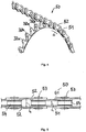
- FIG. 4 shows a roller chain 50 engaged with a sprocket 10 with chain inner-link pairs 51 and outer chain-link pairs 52.
- the alternating thin and thick teeth 32a, 32b of the chainring 10 represent an already known solution for improving the chain guidance.
- the sprocket 10 rotates in the drive direction DD.
- chain 50 consists of inner chain links and chain outer plates.
- two opposing inner straps or outer straps form an inner strap pair 51 or outer strap pair 52.
- the inner straps and outer straps are hingedly connected in alternation with the chain bolts 53.
- chain rollers 54 are rotatably mounted.
- the inner chain links of a chain inner link pair 51 are arranged at an axial distance D1 to each other.
- the outer chain links of a Kettenau tolaschencrus 52 are arranged at an axial distance D2 to each other. The distance D2 between the chain outer plates is greater than the distance D1 between the chain inner plates.
- distances D1 and D2 define the engagement space for the teeth 32 of the sprocket 10.
- the axial widths of the teeth 32 of the sprocket 10 must be matched to the distances D1 and D2.
- D1 is 2.16mm and D2 is 3.65mm.
- FIG. 6a shows an external perspective view of an embodiment of a mounted on the right pedal crank 2 single chainring 10.
- the chainring 10 has at its radially inner region a hub portion 20 and at its radially outer portion a tooth portion 30 having a plurality of teeth 32. Between the hub region 20 and the tooth region 30, the connecting region 40 extends.
- the connecting portion 40 of this embodiment has a number of six arms 41 includes.
- the crank assembly consisting of the crank 2 and the chainring 10, rotates about the axis of rotation A in the drive direction DD.
- the arms 41 in the connecting region 40 are arranged relative to the pedal crank 2 so that the upper and lower dead center of the crank assembly is taken into account.
- the connection region 40 is free of arms 41 in the regions of the dead points, because only little force is transmitted from the crank 2 to the chainring 10 here.
- the design of the chainring 10 may be designed accordingly open and light in these areas.
- the chainring 10 In the areas outside of the dead centers, in which the pedal force acting on the crank 2 is high, the chainring 10, in particular the connecting region 40, must be designed to be correspondingly stable. In each case three arms 41 are arranged in these two areas outside the dead centers. The arrangement shown of six arms 41 has proven to be a particularly stable and at the same time lightweight construction.
- the pedal force is transmitted to the hub portion 30 of the chainring 10 via the pedal crank 2. From here, the force is transmitted via the arms 41 on the tooth portion 30 and further on a chain, not shown here.
- the sections along the drawn lines AA and CC will be discussed below.
- FIG. 7 shows an enlarged sectional view through the pedal crank assembly FIG. 6b along the line AA.
- the chainring 10 has an outer side 11, which faces in the direction of the crank 2, and one of these opposite inner side 12.
- the regions 20, 30, 40 each have an axial inner plane 29, 39, 49 on the inner side 12 of the chainring 10, an axial Outer plane 27, 37, 47 on the outside 11 of the chainring 10 and an intermediate axial center plane 28, 38, 48 on.
- the inner planes 29, 39, 49 are defined in each case by the axially innermost surfaces of the respective area 20, 30, 40.
- the outer planes 27, 37, 47 are defined in each case by the axially outermost surfaces of the respective area 20, 30, 40.
- the corresponding center planes 28, 38, 48 are each in the middle in between (see also FIG. 9 ).
- the tooth region 30 is offset by a varying offset dimension O in relation to the hub region 20 inward (axial offset or also called offset).
- Measured from the outer tooth plane 37 to the Hub outer plane 27 on the outer side 11 of the sprocket 10 is the dimension O of the axial offset, for example, 6.15 mm.
- the overall axial width G of the chainring 10 is measured from the hub outer plane 27 to the connecting inner plane 49 and corresponds to the maximum width of the sprocket 10.
- the total width G is, for example, 10.9 mm.
- the material thickness of the profiled arm 41 is chosen as low as possible.
- the axial width G1 - measured from the hub outer plane 27 to the profile bottom 45 of the arm 41 - is for example 9.9 mm. That is, the material thickness of the arm 41 on the profile bottom 45 is only 1 mm, which is very low compared to the overall width G.
- the axial width G2 measured from the hub outer plane 27 to the tooth inner plane 39 is less than the overall axial width G.
- the axial width G2 is for example 9.75 mm.
- connection inner plane 49 extends axially further inside than the tooth inner plane 39.
- the connecting region 40 hangs inwardly in the axial direction over the tooth region 30.
- the axial overhang Ü inward in this example case is 1.15 mm (10.9 mm minus 9.75 mm) - cf.
- the hub outer plane 27 extends through the abutment surface 24 of the hub portion 20 for the crank 2.
- FIG. 8a shows an enlarged sectional view through the pedal crank assembly FIG. 6b along the line CC.
- the circled detail shows a cross section through the profiled arm 41 and is in FIG. 8b shown enlarged.
- the arm 41 has a thin-walled, U-shaped profile 42.
- the profile 42 has a first and second profile wall 43, 44, which are connected to a profile bottom 45.
- the material thickness P1, P2 of the profile walls 43, 44 and the material thickness P3 of the tread 45 are approximately equal.
- the material thickness of the profile 42 could be about 1 mm to 1.5 mm.
- the material thickness of the arm profile 42 is dimensioned small - cf. For this FIG. 9 ).
- the profile width VB of the arm 41 decreases in the direction of the outer ring 31 of the toothed region 30. Due to the larger lever arm or the greater distance to the tooth region 30, where the chain forces attack, the cross section of the arms 41 in the hub region 20 must be sized larger than in the direction of the tooth region 30. In addition, the profiled arms 41 act in the drive direction DD as pressure rods , The profile thickness PD of the arm 41 is designed according to the stiffness requirements in the drive direction.
- FIG. 9 shows a further section through the crank assembly FIG. 6b ,
- the maximum axial widths NB, VB, ZB, measured from the respective inner plane 29, 39, 49 to the respective outer plane 27, 37, 47 are shown for the regions 20, 30, 40.
- the middle planes 28, 38, 48 are drawn between the respective inner and outer planes as dashed lines.
- the hub outer plane 27 lies in the axial direction A farther outward than the connecting outer plane 47 and the tooth outer plane 37.
- the connecting outer plane 47 lies axially further outward than the tooth outer plane 37.
- the inner hub plane 29 lies in the axial direction A farther outward than the inner tooth plane 39 and the connecting inner plane 49.
- the connection inner plane 49 lies axially further inwardly than the tooth inner plane 39. This produces the axial overhang Ü in the connection region 40. Measured from the connection inner plane 49 to the tooth center plane 38, the overhang is indicated as Ü1.
- the tooth center plane 38 and the connecting medium plane 48 are close together. The closer the center planes 38, 48 are to each other, the more balanced the skew can be taken in both axial directions - both on the smallest pinion 62 outwards and on the largest pinion 61 inward. Compare to the skew FIG. 3 , Depending on the direction in which the center planes 38, 48 are offset from one another, the more the skew can be taken up in one or the other axial direction. In the case shown, the connecting plane 48 extends slightly to the outside axially offset from the tooth center plane 38. This arrangement allows the internal skew on the largest pinion 61st which is most pronounced in sprocket assemblies with an increased number of pinions.
- the hub portion 20 has an axial width NB which is dimensioned from the hub outer plane 27 to the hub inner plane 29.
- the connection region 40 has a maximum axial width VB, which is dimensioned from the connection outer plane 47 to the connection inner plane 49.
- the tooth region 30 has a maximum axial width ZB, which is dimensioned from the outer tooth plane 37 to the inner tooth plane 39, and in this case corresponds to the tooth width Z1 of the thick tooth 32b.
- the axial width VB in the connection region 40 is particularly large in order to increase the rigidity.
- the connection region 40 extends in the axial direction even beyond the tooth inner plane 39 by the overhang dimension Ü.
- the axial width VB in the connection region 40 is dimensioned significantly greater than the axial width NB, ZB of the hub region 20 and the tooth region 30.
- the material thickness P of the arm profile 42 in the connection region 40 is chosen as low as possible in order to keep the weight low.
- the axial offset O1 of the toothed area 30 relative to the hub region 20, alternatively from the hub outer plane 27 to the tooth middle plane 38, is measured.
- the overhang U1 of the connection region 40 can be dimensioned from the connection inner plane 49 to the tooth middle plane 38.
- the dimensions O1 and Ü1 increase in relation to the dimensions O and Ü accordingly by half a tooth width.
- FIGS. 10a to 10e the chain ring 10 is shown in different views.
- the hub region 20, the connection region 40 and the tooth region 30 are lined up.
- the connecting portion 40 connects the hub portion 20 with the tooth portion 30.
- the hub portion 20 has at its radially inner end an inner profile 21 for transmitting torque from the crank to the sprocket 10.
- the tooth portion 30 has a plurality of teeth 32 at the radially outer end of the chainring 10.
- an even number of 36 teeth is arranged, which comprises a first group of teeth 32a and a second group of teeth 32b.
- the teeth 32a of the first group are in the axial direction formed narrower than the teeth 32b of the second group.
- the wide teeth 32b are sized to be suitable only for engagement with outer chain pair pairs 52.
- the narrow teeth 32a are correspondingly narrower and therefore also suitable for engagement in inner link pairs 51.
- the surfaces of the thick teeth 32b lying in the axial direction A on the inside define the tooth inner plane 39.
- the connecting portion 40 is formed by the arms 41.
- the arms 41 connect the hub portion 20 to the tooth portion 30.
- the space between the arms 41 is free of material to save weight. More specifically, the arms 41 extend between the inner race 22 of the boss portion 20 and an outer race 31 of the tooth portion 30.
- the arms 41 extend from the boss portion 20 toward the tooth portion 30 both in width (in the axial direction) and in thickness.
- the inner ring 22 of the hub portion 20 is disposed adjacent to the inner profile 21.
- the outer ring 31 of the tooth portion 30 is disposed radially inside the teeth 32.
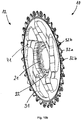
- FIG. 10c shows the outer side 11 of the chainring 10 with the outwardly open U-shaped profile 42 of the six arms 41st
- FIG. 10d shows the inside 12 of the chainring 10th
- FIG. 10d shows a plan view of the chainring 10 with the areas 20, 30, 40th
- the chainrings 10 shown here are circular. However, it would also be possible to form the chainring not circular, but for example oval. Such oval chainrings minimize the less effective areas or dead centers of the crank assembly.
- the inventive design of the Bonding area is also applicable to such oval chainrings to increase the rigidity.
- the Figures 11a and 11b show an outer and an inner view of an enlarged partial section of the sprocket 10. Between each two adjacent teeth 32, a tooth base 35 is arranged. The root diameter 36 runs tangentially to the tooth roots 35.
- the thick teeth 32b of the second tooth group have thickenings 34.
- the thin teeth 32a are free of thickening. These thickenings 34 extend in the radial direction from the tooth tip 33 via the tooth root to beyond the root diameter 36. In other words, the thickenings 34 of the thick teeth extend 32b in the radial direction to below the tooth base 35. This compared to known designs in the radial direction significantly longer formed thickening 34 and the material thus obtained makes the tooth 32b more stable. As is clear from the FIGS.
- the thickening 34 is equally formed on the outside 11 and on the inside 12 of the sprocket 10 and the tooth 32b and thus extends on both sides of the tooth tip 33 to below the Wegnikischen messrs 36.
- the remaining material in the teeth 32 and the outer ring 31 can be removed, for example, by milling to the extent of the narrow teeth 32 a. This further saves weight.
- the chain ring 10 can be made of aluminum by machining processing, for example by milling precise and easy.
- the cross-sectional enlargement of the profile arms 41 in the connection region 40 beyond the tooth inner plane 39, allows a particularly low material thickness of the profile with sufficient rigidity.
- the chain ring 10 is sufficiently stable and lightweight as possible.
Landscapes
- Engineering & Computer Science (AREA)
- Mechanical Engineering (AREA)
- Chemical & Material Sciences (AREA)
- Combustion & Propulsion (AREA)
- Transportation (AREA)
- General Engineering & Computer Science (AREA)
- Gears, Cams (AREA)
- Valve-Gear Or Valve Arrangements (AREA)
- Devices For Conveying Motion By Means Of Endless Flexible Members (AREA)
Abstract
Description
- Kettenantriebe in Fahrrädern haben schon eine lange Entwicklungsgeschichte hinter sich. Entsprechend sich ändernder Anforderungen waren dabei immer wieder unterschiedliche Erfordernisse zu erfüllen.
- Ausgangspunkt war ein Eingang-Kettenantrieb mit einem Einfach-Kettenrad (vorderes Kettenrad) an der Tretkurbel in Kombination mit einem Einfach-Ritzel (hinteres Kettenrad) an der Nabe am Hinterrad, wobei die Kopplung von vorderem und hinterem Kettenrad mittels einer Rollenkette erfolgte.
- Dieses Konzept wurde bei Mehrgang-Antrieben mit Umschalt-Einrichtungen zum Umlegen der Rollenkette (vorderer Kettenwerfer und hinteres Schaltwerk) zwischen benachbarten Kettenrädern grundsätzlich beibehalten. Die Umschalteinrichtungen wurden mit Kettenspann-Einrichtungen ergänzt. Die Anforderungen zum sicheren Eingreifen der Rollenkette an den Zähnen der Kettenräder erhöhten sich infolge des Kettenschräglaufs zwischen der Mehrzahl von axial nebeneinander angeordneten vorderen Kettenrädern einerseits und hinteren Kettenrädern andererseits.
- In Verbindung mit der Einführung und Weiterentwicklung von Mountain-Bikes (MTB) wurde die Anzahl von vorderen Kettenrädern bis auf drei ausgedehnt. Der Kettenschräglauf erhöhte sich dabei entsprechend.
- In jüngster Zeit wurden Kettenantriebe dahingehend abgewandelt, dass sie lediglich über ein einziges vorderes Kettenrad (Einzelkettenblatt oder -rad) verfügen müssen. Dazu waren Detaillösungen notwendig, wie eine Zahngeometrie mit alternierenden dicken und dünnen Zähnen, die auch ohne eine vorhandene Kettenführung eines vorderen Kettenwerfers auskommt und dennoch ein sehr sicheres Eingreifen der Rollenkette am vorderen Kettenrad ermöglicht.
- Um dennoch eine erforderliche Spreizung der zur Verfügung stehenden Gänge zu erreichen, kommen Mehrfach-Ritzelanordnungen mit einer großen Anzahl von 11, 12 oder 13 Ritzeln zum Einsatz. Es werden sehr große Ritzel mit um die 50 Zähne eingesetzt, die den Bauraum ausnutzen, der infolge der geneigten Erstreckung der Speichen zwischen dem inneren Nabenflansch und der äußeren Felge zur Verfügung steht. Die großen Ritzel dieser Mehrfach-Ritzelanordnung sind im Vergleich zu herkömmlichen Anordnungen sehr weit innen - in Richtung der Nabenmitte oder Rahmenmitte - angeordnet.
- Für eine ideale Kettenlinie befinden sich das vordere Einzel-Kettenblatt und das Ritzel in derselben geometrischen Ebene, so dass die Kette keinen Schräglauf erfährt. In diesem Idealzustand wäre der Kettenverschleiß minimal und der Wirkungsgrad des Antriebsstranges maximal. Dieser Zustand kann jedoch nicht für jedes Ritzel der Mehrfach-Ritzelanordnung hergestellt werden. Auf den kleinsten und größten Ritzeln ist der Kettenschräglauf besonders groß.
- Die kleinen Ritzel der Mehrfach-Ritzelanordnung sind axial weiter außen als die großen Ritzel angeordnet. Umgekehrt sind die großen Ritzel axial weiter innen als die kleinen Ritzel angeordnet. In radialer Richtung sind die Zähne außen am Ritzel und am Kettenrad angeordnet. Das Profil zur Drehmomentübertragung ist radial innen am Ritzel und/oder am Kettenrad angeordnet.
- Die vorderen Einzel-Kettenräder sind im Vergleich zu den in Mehrfach-Anordnungen vorhandenen großen Kettenrädern vergleichsweise klein und damit relativ stabil. Diesem Stabilitätsvorteil stehen aber größere Kettenzugskräfte gegenüber, die infolge des geänderten Übersetzungsverhältnisses zwischen beibehaltener Kurbellänge und reduziertem Kettenraddurchmesser entstehen können.
- Bei nicht ausreichender Steifigkeit des Kettenrades, wie zum Beispiel beim Anliegen von sehr großen Kettenzugkräften, kann das Kettenrad seitlich ausknicken und wird dabei zerstört. Dieses Problem verstärkt sich, wenn der Kettenschräglauf erhöht wird, zum Beispiel durch eine axiale Verlagerung der größten Ritzel nach axial innen, hin zu den Speichen des hinteres Laufrades im Zuge einer Erhöhung der Anzahl der Ritzel. Die Kettenzugkräfte infolge des hohen Kettenschräglaufs sind besonders groß, wenn die Kette mit einem der großen, weit innenliegenden Ritzel in Eingriff steht. Hier ist die Gefahr des Abknickens des Kettenblatts am Größten.
- Bei der Auslegung der Kettenblätter müssen einerseits die gestiegenen Stabilitätsanforderungen und andererseits die nunmehr bestehenden Leichtbau-Erfordernisse berücksichtigt werden. Hier spielt sowohl die Materialwahl (Gewicht und Festigkeit), als auch die Geometrie (Steifigkeit) eine Rolle.
- Die Kettenzugkraft wird an den Zähnen des Kettenrades in der Zahnmittelebene in die Zähne eingeleitet, wobei die Richtung der Kettenzugkraft infolge des Kettenschräglaufes zu einem hinteren Ritzel eines Mehrfach-Ritzelsatzes nicht parallel zu der Zahnmittelebene ist.
- Einerseits soll die Zahnmittelebene des Kettenrads, um den Kettenschräglauf einzuschränken, möglichst mittig zum Mehrfach-Ritzelsatz angeordnet sein. Andererseits ist der Nabenbereich des Kettenrads aufgrund von vorgegebenen Rahmen- und Kurbelanschlussmaßen nicht frei variierbar. Dies führt dazu, dass das Kettenrad einen Versatz (offset) in axialer Richtung zwischen seiner Nabenmittelebene und seiner Zahnmittelebene aufweist. Insbesondere ist die Zahnmittelebene relativ zu der Nabenmittelebene nach innen versetzt.
- Bei bekannten Kettenrädern (Vorgänger-Kettenräder von SRAM) besteht zwischen der Zahnmittelebene und der Mittelebene durch den radial inneren Nabenbereich (Nabenmittelebene) des Kettenrades ein axialer Versatz. Dieser Versatz ergibt sich zwangsläufig, weil andere Konstruktionsmaße vorgegeben sind (Standard) und die Abwandlungen bei verschiedenen Anschlussbedingungen am Kettenrad umgesetzt werden. So kann man einerseits ein genormtes Maß für den gegenständlichen axialen Anschlag an der Kurbel für das Kettenrad einhalten und andererseits trotzdem dem Erfordernis nach unterschiedlich großen Maßen für die Kettenlinie entsprechen. Der gewählte Versatz hängt von mehreren Faktoren, wie der eingesetzten Mehrfach-Ritzelanordnung, deren axiale Positionierung gegenüber dem Kettenblatt, den Rahmenmaßen, der Nabenbreite und dem verwendetem Kurbelstandard ab.
- Dieser Versatz in axialer Richtung zwischen der Zahnmittelebene und der Nabenmittelebene erhöht die Anfälligkeit zum Abknicken des Kettenrades weiter. Die Anforderungen an die Stabilität des Kettenrades werden mit der Erhöhung der Zähnezahl und somit der Vergrößerung des Kettenraddurchmessers aufgrund des sich vergrößernden Hebels weiter erhöht.
- Es stellt sich die Aufgabe, ein Kettenrad bereit zu stellen, das die genannten Anforderungen erfüllt. Das Kettenrad soll über eine ausreichende Stabilität, geringes Gewicht und gute Kettenführungseigenschaften verfügen und muss dabei auch den vorgegebenen Bauraum berücksichtigen.
- Diese Aufgabe wird durch ein Einzel-Kettenrad nach Anspruch 1 gelöst.
Das Einfach-Kettenrad ist zur Montage an einer um eine Drehachse drehbar gelagerten Tretkurbel eines Fahrrades und zum Eingriff in eine Fahrradkette mit Ketteninnenlaschenpaaren und Kettenaußenlaschenpaaren geeignet. Das Kettenrad weist eine axiale Außenseite und eine axiale Innenseite auf. Weiter weist das Kettenrad einen Nabenbereich mit einem Innenprofil am radial inneren Ende des Kettenrades zur Drehmomentübertragung von der Tretkurbel auf das Kettenrad auf. - Der Nabenbereich definiert eine axiale Nabenmittelebene zwischen einer Nabenaußenebene und einer Nabeninnenebene. Das Kettenrad weist weiter einen Zahnbereich mit einer Vielzahl von Zähnen an einem radial äußeren Ende des Kettenrades zum Eingriff in die Fahrradkette auf.
- Der Zahnbereich definiert eine axiale Zahnmittelebene zwischen einer Zahnaußenebene und einer Zahninnenebene. Die Zahninnenebene ist durch die in axialer Richtung am weitesten innen liegenden Oberflächen der Vielzahl von Zähnen definiert. Weiter weist das Kettenrad einen Verbindungsbereich auf, der sich in radialer Richtung zwischen dem Nabenbereich und dem Zahnbereich des Kettenrades erstreckt und diese miteinander verbindet. Der Verbindungsbereich definiert eine Verbindungsmittelebene zwischen einer Verbindungsaußenebene und einer Verbindungsinnenebene. Die Verbindungsinnenebene ist durch die in axialer Richtung am weitesten innen liegenden Oberflächen des Verbindungsbereichs definiert. Die Zahnmittelebene verläuft in axialer Richtung nach innen versetzt zu der Nabenmittelebene, wobei zur Erhöhung der Steifigkeit des Kettenrades die Verbindungsinnenebene des Verbindungsbereichs in axialer Richtung nach innen versetzt zu der Zahninnenebene des Zahnbereichs verläuft.
- Es hat sich gezeigt, dass die Stabilität des Kettenrades merklich erhöht werden kann, wenn die Verbindungsinnenebene zur Vergrößerung des tragenden Querschnittes im Verbindungsbereich einseitig nach axial innen größer dimensioniert wird. Gerade wenn die Verbindungsinnenebene axial innerhalb der Zahninnenebene verläuft, also der Querschnitt des Verbindungsbereichs in axialer Richtung bis über die Zahninnenebene reicht, ist die Steifigkeit besonders hoch.
- Gemäß einer Ausführungsform des Kettenrades wird der Verbindungsbereich von einer Mehrzahl von Armen gebildet. Die Mehrzahl von Armen erstreckt sich vom Nabenbereich zum Zahnbereich und verbindet diese miteinander.
- Der Verbindungsbereich könnte auch geschlossen oder geschlossen mit Durchbrüchen ausgebildet sein. Die Ausführungsform mit einer Mehrzahl von Armen ohne Material zwischen den Armen ist besonders leichtgewichtig.
- Insbesondere die Anordnung von Armen im Verbindungsbereich des Kettenrades außerhalb der Totpunkte der Kurbelanordnung hat sich als effektiv erwiesen. In den Bereichen des Kettenblattes, an denen hohe Kräfte von der Kurbel über das Kettenrad auf die Kette übertragen werden, muss das Kettenblatt besonders stabil ausgebildet sein. Hier werden die Arme angeordnet. Die weniger belasteten Bereiche des Kettenblatts in den beiden Totpunkten der Kurbelanordnung können frei von Armen bleiben. Auf diese Weise kann weiter Gewicht gespart werden.
Gemäß einer Ausführungsform des Kettenrades sind die Arme im Querschnitt profilträgerförmig ausgebildet. Insbesondere weisen die Arme einen dünnwandigen offenen Querschnitt 42 auf. Die Wandstärke bzw. Materialstärke des Querschnitts ist relativ zu der axialen Breite des Verbindungsbereichs gering. Mit Querschnitt ist das Profil der Arme gemeint. Dieses Profil soll in erster Linie dünnwandig ausgebildet sein. Welche Form das Profil aufweist ist zweitrangig. - Gemäß einer Ausführungsform ist der Querschnitt der Arme im Wesentlichen u-förmig ausgebildet. Das u-förmige Profil weist insbesondere eine erste und zweite Profilwand und einen Profilboden auf, deren Materialstärke im Vergleich zur axialen Breite des Verbindungsbereichs gering bemessen ist.
- Gemäß einer Ausführungsform ist der u-förmige Querschnitt zur Außenseite des Kettenrades hin offen und zur Innenseite des Kettenrades hin geschlossen. Der geschlossene Profilboden des Querschnitts bildet gleichzeitig auf der Innenseite des Kettenblatts den Überhang über die Zahninnenebene hinaus.
- Der dünnwandige offene Querschnitt des Verbindungsbereichs erlaubt zum einen eine einfache Fertigung durch Fräsen, zum anderen gewährleistet das Verhältnis aus vergrößerter Profilbreite und geringer Materialstärke eine gleichermaßen stabile, als auch leichte Konstruktion.
- Gemäß einer Ausführungsform des Kettenrades umfasst die Vielzahl von Zähnen eine erste Gruppe von Zähnen und eine zweite Gruppe von Zähnen.
- Insbesondere weist die erste Gruppe von Zähnen eine erste axiale Breite und die zweite Gruppe von Zähnen eine zweite axiale Breite auf. Die zweite axiale Breite ist größer, als die erste axiale Breite. Insbesondere ist die erste axiale Breite der ersten Gruppe von Zähnen geringer als ein Ketteninnenlaschenabstand eines Ketteninnenlaschenpaares bemessen. Die zweite axiale Breite der zweiten Gruppe von Zähnen ist größer als der Ketteninnenlaschenabstand und kleiner als ein Außenlaschenabstand eines Außenlaschenpaares bemessen. Die dicken und dünnen Zähne verbessern die Kettenführung.
- Gemäß einer Ausführungsform weisen die Zähne der zweiten Gruppe von Zähnen jeweils einen axialen Vorsprung auf, welcher sich in radialer Richtung von der Zahnspitze über den Zahnfuß bis über den Fußkreisdurchmesser hinweg erstreckt. Die in radialer Richtung langgezogene Ausbildung des Vorsprungs verleiht dem Zahn mehr Stabilität.
- Der Fußkreis ist eine gedachte Linie, die tangential zum Zahngrund verläuft.
- Gemäß einer Ausführungsform des Kettenrads ist der Vorsprung an den Zähnen der zweiten Gruppe von Zähnen jeweils an der Außenseite und/oder an der Innenseite ausgebildet. Das heißt, es ist entweder ein Vorsprung auf der axialen Außenseite des Zahnes, oder auf der axialen Innenseite des Zahnes, oder an beiden Seiten des Zahnes ausgebildet.
- Die Vorsprünge können entweder durch Materialabtrag in den übrigen Bereichen, oder durch Materialauftrag im Bereich der Vorsprünge hergestellt werden.
- Gemäß einer Ausführungsform des Kettenrades sind die Zähne der ersten Gruppe in radialer Richtung kürzer als die Zähne der zweiten Gruppe ausgebildet. Umgekehrt sind die Zähne der zweiten Gruppe länger als die Zähne der ersten Gruppe.
- Insbesondere sind die Zähne der zweiten Gruppe sowohl in axialer Richtung, als auch in radialer Richtung größer bemessen, als die Zähne der zweiten Gruppe. Die Ausführungsform gewährleistet eine besonders gute Kettenführung, wie sie bei einem starken Kettenschräglauf notwendig ist.
-
- Fig. 1
- Seitenansicht eines Fahrrads
- Fig. 2
- Schematische Darstellung eines erfindungsgemäßen Fahrradantriebs
- Fig. 3
- Schematische Darstellung der Kettenlinie
- Fig. 4
- Schematische Darstellung eines in eine Kette eingreifenden Kettenrads
- Fig. 5
- Draufsicht auf eine Kette
- Fig. 6a
- Perspektivische Außenansicht des an der Tretkurbel montierten Einzelkettenblatts
- Fig. 6b
- Außenansicht des an der Tretkurbel montierten Einzelkettenblatts
- Fig. 7
- Vergrößerte Schnittdarstellung A-A aus
Fig. 6b - Fig. 8a
- Vergrößerte Schnittdarstellung C-C aus
Fig. 6b - Fig. 8b
- Detail aus Schnittdarstellung
Fig. 8a - Fig. 9
- Vergrößerte Schnittdarstellung durch Kettenradanordnung aus
Fig. 6b - Fig. 10a
- Perspektivische Außenansicht des Kettenblatts
- Fig. 10b
- Perspektivische Innenansicht des Kettenblatts
- Fig. 10c
- Außenansicht des Kettenblatts
- Fig. 10d
- Innenansicht des Kettenblatts
- Fig. 10d
- Draufsicht auf das Kettenblatt
- Fig. 11a
- Außenansicht eines vergrößerten Teilausschnitts des Kettenblatts
- Fig. 11b
- Innenansicht des vergrößerten Teilausschnitts
- Fig. 11c
- Perspektivische Außenansicht eines Teilausschnitts
- Die im Folgenden verwendeten Richtungsangaben vorne und hinten beziehen sich auf ein Fahrrad in Fahrtrichtung. Axial außen und axial innen beziehen sich auf die Außen- und Innenseite des Kettenblatts in seiner für die Montage vorgesehenen Ausrichtung. Die Außenseite eines an der vorderen, rechten Tretkurbel montierten Kettenblatts weist nach außen, also vom Rahmen weg. Die Innenseite des Kettenblatts weist nach innen, also zum Rahmen hin. Axial bezieht sich auf die Drehachse A des Kettenblatts bzw. der gesamten Tretkurbelanordnung. Die Zähne sind radial außen am Kettenblatt angeordnet. Der Außendurchmesser des Kettenblatts ist das radial äußere Ende. Der Innendurchmesser das radial innere Ende des Kettenblatts. Die Figuren zeigen Ansichten in verschiedenen Maßstäben.
-
Figur 1 zeigt exemplarisch ein herkömmliches Fahrrad mit einem Fahrradrahmen 1 und einem Fahrradantrieb, bestehend aus einem vorderen Kettenblatt 10, das an der rechten Fahrradkurbel 2 montiert ist, einer Mehrfach-Ritzelanordnung 60 und einer Fahrradkette 50. Die vordere Tretkurbelanordnung, bestehend aus dem Kettenblatt 10 und der Tretkurbel 2, dreht sich um die Drehachse A. Die Mehrfach-Ritzelanordnung 60 umfasst eine erhöhte Anzahl von benachbarten Ritzeln, insbesondere zwölf Ritzeln, die hier nur schematisch dargestellt sind. Die Fahrradkette 50 steht mit den Zähnen des Kettenblatts 10 und den Zähnen eines der Ritzel der Mehrfach-Ritzelanordnung 60 in Eingriff. Mittels der Fahrradkette 50 wird Kraft von der vorderen Tretkurbelanordnung auf die hintere Mehrfach-Ritzelanordnung 60 und von dort über den Antreiber auf die Hinterradnabe übertragen. Das Schaltwerk 70 kann entweder mechanisch, oder elektrisch angesteuert werden. Die Darstellung inFigur 1 soll die Zuordnung der Teile verdeutlichen. Das schematisch gezeigte Kettenrad 10 kann sich von der erfindungsgemäßen Ausführungsform unterscheiden. - Das erfindungsgemäße Kettenblatt ist nicht nur für ein dargestelltes Rennrad geeignet, sondern kann an einer Vielzahl von Fahrradtypen, wie Mountainbikes, Tourenräder oder E-Bikes zum Einsatz kommen. Je nach Antriebsart sind auch Kettenblätter mit anderen Zähnezahlen, als die in den folgenden Figuren dargestellten, möglich. Insbesondere Einzel-Kettenblätter mit 30, 32, 34, 36 oder 38 Zähnen sind gängige Ausführungsformen. Für einen Antrieb mit nur einem vorderen Kettenblatt und dreizehn hinteren Ritzeln sind insbesondere neun, zehn oder elf Zähne auf dem kleinsten Ritzel und 36 Zähne auf dem größten Ritzel möglich.
- Antriebe für Mountainbikes verfügen üblicherweise über eine noch größere Spreizung der Ritzel. Bei Ritzel-Anordnungen mit zwölf Ritzeln stellen zehn Zähne am kleinsten Ritzel und 50 Zähne am größten Ritzel oder elf Zähne am kleinsten und 55 Zähne am größten Ritzel eine sinnvolle Spreizung dar.
-
Figur 2 zeigt eine schematische Darstellung eines Fahrradantriebs. Die vordere Kettenblatt-Anordnung umfasst ein einzelnes Kettenblatt 10, welches sich um eine Drehachse A dreht. Die Mehrfach-Ritzelanordnung 60 umfasst zwölf Ritzel mit einem größten Ritzel 61 mit 50 Zähnen und einem kleinsten Ritzel 62 mit 10 Zähnen. In dem gezeigten Zustand steht die Fahrradkette 50 mit den Zähnen des Kettenblatts 10 und mit den Zähnen des größten Ritzels 62 der Mehrfach-Ritzelanordnung 60 in Eingriff. Das Schaltwerk 70 bewegt die Fahrradkette 50 beim Schalten von einem Ritzel auf ein benachbartes Ritzel. Das Schaltwerk kann dabei entweder mechanisch, oder elektrisch bedient werden. Im gezeigten Ausführungsbeispiel mit nur einem Kettenblatt 10 entfällt der vordere Umwerfer. -
Figur 3 zeigt zur Verdeutlichung der verschiedenen Kettenlinien KL eine weitere schematische Darstellung eines Fahrradantriebs. Das Kettenblatt 10 ist im Verhältnis zur Mehrfach-Ritzelanordnung 60 so ausgerichtet, dass ein neutraler Verlauf der Kettenlinie KL vorliegt, wenn die Kette mit einem der mittleren Ritzel in Eingriff steht. Die neutrale Kettenlinie entspricht dem idealen Verlauf der Kette, bei dem so gut wie kein Kettenschräglauf auftritt - siehe mittlere KL. Befindet sich die Kette auf dem kleinsten Ritzel 62 oder größten Ritzeln 61, ist der Kettenschräglauf entsprechend am Stärksten. Für diesen Fall muss das Kettenblatt 10 ausreichend steif ausgebildet sein, um die Kettenkräfte aufnehmen zu können. Das erfindungsgemäße Kettenrad 10 kann vor allem die Kräfte verursacht durch den Kettenschräglauf auf dem größten Ritzel 61 gut aufnehmen. -
Figur 4 zeigt eine mit einem Kettenrad 10 in Eingriff stehende Rollenkette 50 mit Ketteninnenlaschenpaaren 51 und Kettenaußenlaschenpaaren 52. Die alternierenden dünnen und dicken Zähne 32a, 32b des Kettenblatts 10 stellen eine bereits bekannte Lösung zur Verbesserung der Kettenführung dar. Das Kettenrad 10 dreht sich in Antriebsrichtung DD. - Die in
Figur 5 in der Draufsicht dargestellte Kette 50 besteht aus Ketteninnenlaschen und Kettenaußenlaschen. Jeweils zwei gegenüberliegende Innenlaschen bzw. Außenlaschen bilden ein Innenlaschenpaar 51 bzw. Außenlaschenpaar 52. Die Innenlaschen und Außenlaschen sind im Wechsel mit Kettenbolzen 53 gelenkig verbunden. Auf den Krägen der Innenlaschen sind Kettenrollen 54 drehbar gelagert. Die Ketteninnenlaschen eines Ketteninnenlaschenpaars 51 sind in einem axialen Abstand D1 zueinander angeordnet. Die Kettenaußenlaschen eines Kettenaußenlaschenpaars 52 sind in einem axialen Abstand D2 zueinander angeordnet. Dabei ist der Abstand D2 zwischen den Kettenaußenlaschen größer, als der Abstand D1 zwischen den Ketteninnenlaschen. Diese Abstände D1 und D2 definieren den Eingriffsraum für die Zähne 32 des Kettenrads 10. Um ein sauberes Eingreifen in die Kette 50 zu ermöglichen, müssen die axialen Breiten der Zähne 32 des Kettenrads 10 auf die Abstände D1 und D2 abgestimmt sein. Beispielsweise ist D1 mit 2,16 mm und D2 mit 3,65 mm bemessen. -
Figur 6a zeigt eine perspektivische Außenansicht einer Ausführungsform eines an der rechten Tretkurbel 2 montierten Einzel-Kettenblatts 10. Das Kettenblatt 10 weist an seinem radialen Innenbereich einen Nabenbereich 20 und an seinem radialen Außenbereich einen Zahnbereich 30 mit einer Vielzahl von Zähnen 32 auf. Zwischen dem Nabenbereich 20 und dem Zahnbereich 30 erstreckt sich der Verbindungsbereich 40. Das Kettenblatt 10 besteht in radialer Richtung gesehen also aus einem Nabenbereich 30, einem Verbindungsbereich 40 und einem Zahnbereich 30. - Aus der Außenansicht der Tretkurbelanordnung in
Figur 6b wird deutlich, dass der Verbindungsbereich 40 dieser Ausführungsform eine Anzahl von sechs Armen 41 umfasst. Die Kurbelanordnung, bestehend aus der Kurbel 2 und dem Kettenblatt 10, dreht sich um die Drehachse A in die Antriebsrichtung DD. Die Arme 41 im Verbindungsbereich 40 sind relativ zur Tretkurbel 2 so angeordnet, dass der obere und untere Totpunkt der Kurbelanordnung berücksichtigt wird. Der Verbindungsbereich 40 ist in den Bereichen der Totpunkte frei von Armen 41, weil hier nur wenig Kraft von der Kurbel 2 auf das Kettenblatt 10 übertragen wird. Die Auslegung des Kettenblatts 10 kann in diesen Bereichen entsprechend offen und leicht gestaltet sein. In den Bereichen außerhalb der Totpunkte, in denen die auf die Kurbel 2 wirkende Pedalkraft hoch ist, muss das Kettenblatt 10 insbesondere der Verbindungsbereich 40 entsprechend stabil ausgebildet sein. Jeweils drei Arme 41 sind in diesen beiden Bereichen außerhalb der Totpunkte angeordnet. Die gezeigte Anordnung von sechs Armen 41 hat sich als eine besonders stabile und gleichzeitig leichte Konstruktion erwiesen. Die Pedalkraft wird über die Tretkurbel 2 auf den Nabenbereich 30 des Kettenblatts 10 übertragen. Von hier wird die Kraft über die Arme 41 auf den Zahnbereich 30 und weiter auf eine hier nicht gezeigte Kette übertragen. Auf die Schnitte entlang der eingezeichneten Linien A-A und C-C wird im Folgenden eingegangen. -
Figur 7 zeigt eine vergrößerte Schnittdarstellung durch die Tretkurbelanordnung ausFigur 6b entlang der Linie A-A. Hier wird die Anordnung der Bereiche 20, 30, 40 des Kettenblatts 10 in axialer Richtung deutlich. Das Kettenblatt 10 hat eine Außenseite 11, welche in Richtung der Kurbel 2 weist, und eine dieser gegenüberliegenden Innenseite 12. Die Bereiche 20, 30, 40 weisen jeweils eine axiale Innenebene 29, 39, 49 auf der Innenseite 12 des Kettenblatts 10, eine axiale Außenebene 27, 37, 47 auf der Außenseite 11 des Kettenblatts 10 und eine dazwischen liegende axiale Mittelebene 28, 38, 48 auf. Die Innenebenen 29, 39, 49 werden jeweils durch die in axialer Richtung am weitesten innen liegenden Oberflächen des jeweiligen Bereichs 20, 30, 40 definiert. Die Außenebenen 27, 37, 47 werden jeweils durch die in axialer Richtung am weitesten außen liegenden Oberflächen des jeweiligen Bereichs 20, 30, 40 definiert. Die entsprechenden Mittelebenen 28, 38, 48 liegen jeweils mittig dazwischen (vgl. auchFigur 9 ). Der Zahnbereich 30 ist um ein variierendes Versatzmaß O gegenüber dem Nabenbereich 20 nach innen versetzt (Axialversatz oder auch offset genannt). Gemessen von der Zahnaußenebene 37 bis zur Nabenaußenebene 27 auf der Außenseite 11 des Kettenrads 10 beträgt das Maß O des Axialversatzes beispielsweise 6,15 mm. - Die axiale Gesamtbreite G des Kettenblatts 10 wird gemessen von der Nabenaußenebene 27 bis zur Verbindungsinnenebene 49 und entspricht der maximalen Breite des Kettenblatts 10. Die Gesamtbreite G beträgt beispielsweise 10,9 mm. Um Gewicht zu sparen, ist die Materialstärke des profilierten Arms 41 möglichst gering gewählt. Die axiale Breite G1 - von der Nabenaußenebene 27 bis zum Profilboden 45 des Arms 41 gemessen - beträgt beispielsweise 9,9 mm. Das heißt, die Materialstärke des Arms 41 am Profilboden 45 beträgt nur 1 mm, was im Vergleich zur Gesamtbreite G sehr gering ist. Die axiale Breite G2 gemessen von der Nabenaußenebene 27 bis zur Zahninnenebene 39 ist geringer als die axiale Gesamtbreite G. Die axiale Breite G2 beträgt beispielsweise 9,75 mm. Somit ergibt sich, dass die Verbindungsinnenebene 49 axial weiter innen als die Zahninnenebene 39 verläuft. Mit anderen Worten hängt der Verbindungsbereich 40 in axialer Richtung nach innen über den Zahnbereich 30. Der axiale Überhang Ü nach innen beträgt in diesem Beispielsfall 1,15 mm (10,9 mm minus 9,75 mm) - vgl. auch
Figur 9 . Die Nabenaußenebene 27 verläuft durch die Anschlagsfläche 24 des Nabenbereichs 20 für die Kurbel 2. -
Figur 8a zeigt eine vergrößerte Schnittdarstellung durch die Tretkurbelanordnung ausFigur 6b entlang der Linie C-C. Der eingekreiste Detailausschnitt zeigt einen Querschnitt durch den profilierten Arm 41 und ist inFigur 8b vergrößert dargestellt. Mit diesen Darstellungen wird das Verhältnis zwischen der vergleichsweise großen axialen Gesamtbreite G des Kettenblatts 10 gemessen von der Nabenaußenebene 27 bis zur Verbindungsinnenebene 39 und der vergleichsweise geringen Materialstärke des Armprofils 42 deutlich. Der Arm 41 weist ein dünnwandiges, u-förmiges Profil 42 auf. Das Profil 42 hat eine erste und zweite Profilwand 43, 44, die mit einem Profilboden 45 verbunden sind. Die Materialstärke P1, P2 der Profilwände 43, 44 und die Materialstärke P3 des Profilbodens 45 sind in etwa gleich groß. Beispielsweise könnte die Materialstärke des Profils 42 etwa 1 mm bis 1,5 mm betragen. Im Vergleich zur Gesamtbreite G von etwa 10,9 mm ist dies gering. Auch im Vergleich zur maximalen Profilbreite VB des Armprofils 42 im Verbindungsbereich 40, gemessen von der Verbindungsinnenebene 49 bis zur Verbindungsaußenebene 47, ist die Materialstärke des Armprofils 42 gering bemessen - vgl. hierzuFigur 9 ). - Die Profilbreite VB des Arms 41 nimmt in Richtung des Außenrings 31 des Zahnbereichs 30 ab. Aufgrund des größeren Hebelarms bzw. des größeren Abstands zum Zahnbereich 30, wo die Kettenkräfte angreifen, muss der Querschnitt der Arme 41 in Richtung Nabenbereich 20 größer bemessen sein, als in Richtung des Zahnbereichs 30. Außerdem wirken die profilierten Arme 41 in Antriebsrichtung DD als Druckstäbe. Die Profildicke PD des Arms 41 ist entsprechend auf die Steifigkeitsanforderungen in Antriebsrichtung ausgelegt.
-
Figur 9 zeigt einen weiteren Schnitt durch die Kurbelanordnung ausFigur 6b . Hier sind unter anderem für die Bereiche 20, 30, 40 jeweils die maximalen axialen Breiten NB, VB, ZB, gemessen von der jeweiligen Innenebene 29, 39, 49 zur jeweiligen Außenebene 27, 37, 47 eingezeichnet. Auch die Mittelebenen 28, 38, 48 sind zwischen den jeweiligen Innen- und Außenebenen als Strichlinien eingezeichnet. Die Nabenaußenebene 27 liegt in axialer Richtung A weiter außen als die Verbindungsaußenebene 47 und die Zahnaußenebene 37. Die Verbindungsaußenebene 47 liegt axial weiter außen als die Zahnaußenebene 37. Die Nabeninnenebene 29 liegt in axialer Richtung A weiter außen als die Zahninnenebene 39 und die Verbindungsinnenebene 49. Allerdings liegt die Verbindungsinnenebene 49 axial weiter innen als die Zahninnenebene 39. Dies erzeugt den axialen Überhang Ü im Verbindungsbereich 40. Gemessen von der Verbindungsinnenebene 49 bis zur Zahnmittelebene 38 ist der Überhang als Ü1 eingezeichnet. - Die Zahnmittelebene 38 und die Verbindungsmittelebene 48 liegen eng beieinander. Je näher die Mittelebenen 38, 48 zusammenliegen, desto ausgewogener kann der Schräglauf in beide axialen Richtungen - sowohl am kleinsten Ritzel 62 nach außen, als auch am größten Ritzel 61 nach innen - aufgenommen werden. Vergleiche zum Schräglauf
Figur 3 . Je nachdem in welche Richtung die Mittelebenen 38, 48 zueinander versetzt verlaufen, desto mehr kann der Schräglauf in die eine oder andere axiale Richtung aufgenommen werden. Im gezeigten Fall verläuft die Verbindungsmittelebene 48 leicht nach axial außen versetzt zur Zahnmittelebene 38. Diese Anordnung erlaubt es, den Innenschräglauf auf dem größten Ritzel 61 aufzunehmen, welcher bei Ritzelanordnungen mit einer erhöhten Anzahl von Ritzeln am stärksten ausgeprägt ist. - Der Nabenbereich 20 weist eine axiale Breite NB auf, welche von der Nabenaußenebene 27 bis zur Nabeninnenebene 29 bemessen wird. Der Verbindungsbereich 40 weist eine maximale axiale Breite VB auf, welche von der Verbindungsaußenebene 47 bis zur Verbindungsinnenebene 49 bemessen wird. Der Zahnbereich 30 weist eine maximal axiale Breite ZB auf, welche von der Zahnaußenebene 37 bis zur Zahninnenebene 39 bemessen wird, und in diesem Fall der Zahnbreite Z1 des dicken Zahns 32b entspricht. Die axiale Breite VB im Verbindungsbereich 40 ist, um die Steifigkeit zu erhöhen, besonders groß. Insbesondere erstreckt sich der Verbindungsbereich 40 in axialer Richtung sogar über die Zahninnenebene 39 um das Überhangmaß Ü hinaus. Die axiale Breite VB im Verbindungsbereich 40 ist deutlich größer bemessen als die axiale Breite NB, ZB des Nabenbereichs 20 und des Zahnbereichs 30. Gleichzeitig ist die Materialstärke P des Armprofils 42 im Verbindungsbereich 40 möglichst gering gewählt, um das Gewicht niedrig zu halten. Hier wird der Axialversatz O1 des Zahnbereichs 30 relativ zum Nabenbereich 20, alternativ von der Nabenaußenebene 27 bis zur Zahnmittelebene 38 gemessen. Ebenso kann der Überhang U1 des Verbindungsbereichs 40 von der Verbindungsinnenebene 49 bis zur Zahnmittelebene 38 bemessen werden. Die Maße O1 und Ü1 erhöhen sich gegenüber den Maßen O und Ü entsprechend um eine halbe Zahnbreite.
- In den
Figuren 10a bis 10e wird der Kettenring 10 in verschiedenen Ansichten gezeigt. In radialer Richtung reihen sich der Nabenbereich 20, der Verbindungsbereich 40 und der Zahnbereich 30 aneinander. Der Verbindungsbereich 40 verbindet den Nabenbereich 20 mit dem Zahnbereich 30. - Der Nabenbereich 20 weist an seinem radial inneren Ende ein Innenprofil 21 zur Drehmomentübertragung von der Tretkurbel auf das Kettenrad 10 auf. Der Zahnbereich 30 weist am radial äußeren Ende des Kettenblatts 10 eine Vielzahl von Zähnen 32 auf. Im gezeigten Beispiel ist eine gerade Anzahl von 36 Zähnen angeordnet, welche eine erste Gruppe von Zähnen 32a und eine zweite Gruppe von Zähnen 32b umfasst. Die Zähne 32a der ersten Gruppe sind in axialer Richtung schmäler als die Zähne 32b der zweiten Gruppe ausgebildet. Die breiten Zähne 32b sind so bemessen, dass sie ausschließlich zum Eingriff in Kettenaußenlaschenpaare 52 geeignet sind. Die schmalen Zähne 32a sind entsprechend schmäler und deshalb auch zum Eingriff in Innenlaschenpaare 51 geeignet. Bei Ausführungen mit unterschiedlich dicken Zähnen 32 definieren die in axialer Richtung A am weitesten innen liegenden Oberflächen der dicken Zähne 32b die Zahninnenebene 39.
- Der Verbindungsbereich 40 ist durch die Arme 41 gebildet. Die Arme 41 verbinden den Nabenbereich 20 mit dem Zahnbereich 30. Der Raum zwischen den Armen 41 ist frei von Material, um Gewicht zu sparen. Genauer gesagt erstrecken sich die Arme 41 zwischen dem Innenring 22 des Nabenbereichs 20 und einem Außenring 31 des Zahnbereichs 30. Die Arme 41 nehmen vom Nabenbereich 20 zum Zahnbereich 30 hin sowohl in der Breite (in axialer Richtung), als auch in der Dicke ab. Der Innenring 22 des Nabenbereichs 20 ist benachbart zum Innenprofil 21 angeordnet. Der Außenring 31 des Zahnbereichs 30 ist radial innerhalb der Zähne 32 angeordnet.
- In den perspektivischen Ansichten in
Figur 10a und10b werden die unterschiedlich breiten Zähne 32a, 32b und das u-förmige Profil der Arme 41 deutlich. - Aus den
Figuren 10c und10d ist ersichtlich, dass die breiteren Zähne 32b auch in radialer Richtung länger als die schmalen Zähne 32a ausgebildet sind. Die Zähne der ersten Gruppe 32a sind also sowohl in axialer, als auch in radialer Richtung geringer als die Zähne der zweiten Gruppe 32b bemessen. Dies wirkt sich positiv auf die Kettenführungseigenschaften aus.Figur 10c zeigt die Außenseite 11 des Kettenblatts 10 mit dem nach außen geöffneten u-förmigen Profil 42 der sechs Arme 41.Figur 10d zeigt die Innenseite 12 des Kettenblatts 10.Figur 10d zeigt eine Draufsicht des Kettenblatts 10 mit den Bereichen 20, 30, 40. - Die hier gezeigten Kettenblätter 10 sind kreisrund ausgebildet. Es wäre jedoch auch möglich, das Kettenblatt nicht kreisförmig, sondern beispielsweise oval auszubilden. Solche ovalen Kettenblätter minimieren die weniger wirksamen Bereiche bzw. Totpunkte der Kurbelanordnung. Die erfindungsgemäße Ausgestaltung des Verbindungsbereichs ist auch auf solche ovalen Kettenblätter zur Erhöhung der Steifigkeit anwendbar.
- Die
Figuren 11a und 11b zeigen eine Außen- und eine Innenansicht eines vergrößerten Teilausschnitts des Kettenblatts 10. Zwischen jeweils zwei benachbarten Zähnen 32 ist ein Zahngrund 35 angeordnet. Tangential zu den Zahngründen 35 verläuft der Fußkreisdurchmesser 36. Die dicken Zähne 32b der zweiten Zahngruppe weisen Verdickungen 34 auf. Die dünnen Zähne 32a sind frei von Verdickungen. Diese Verdickungen 34 erstrecken sich in radialer Richtung von der Zahnspitze 33 über den Zahnfuß bis über den Fußkreisdurchmesser 36 hinweg. Mit anderen Worten erstrecken sich die Verdickungen 34 der dicken Zähne 32b in radialer Richtung bis unterhalb des Zahngrunds 35. Diese gegenüber bekannten Ausführungen in radialer Richtung deutlich länger ausgebildete Verdickung 34 und das damit gewonnene Material macht den Zahn 32b stabiler. Wie sich aus denFiguren 11a bis 11b ergibt, ist die Verdickung 34 insbesondere gleichermaßen auf der Außenseite 11 und auf der Innenseite 12 des Kettenrads 10 bzw. des Zahns 32b ausgebildet und erstreckt sich somit auf beiden Seiten von der Zahnspitze 33 bis unterhalb des Fußkreisdurchmessers 36. Das restliche Material im Bereich der Zähne 32 und des Außenrings 31 kann beispielsweise durch Fräsen auf das Maß der schmalen Zähne 32a abgetragen werden. Dies spart weiter Gewicht ein. Der Kettenring 10 kann aus Aluminium durch spanende Verarbeitung beispielsweise durch Fräsen präzise und leicht hergestellt werden. Die Querschnittsvergrößerung der Profilarme 41 im Verbindungsbereich 40 über die Zahninnenebene 39 hinaus, erlaubt eine besonders geringe Materialstärke des Profils bei ausreichender Steifigkeit. Der Kettenring 10 ist ausreichend stabil und möglichst leichtgewichtig.
Claims (12)
- Einfach-Kettenrad 10
zur Montage an einer um eine Drehachse A drehbar gelagerten Tretkurbel 2 eines Fahrrades und zum Eingriff in eine Fahrradkette 50 mit Ketteninnenlaschenpaaren 51 und Kettenaußenlaschenpaaren 52 aufweisend:eine axiale Außenseite 11,eine axiale Innenseite 12,einen Nabenbereich 20 mit einem Innenprofil 21 am radial inneren Ende des Kettenrades 10 zur Drehmomentübertragung von der Tretkurbel 2 auf das Kettenrad 10,wobei der Nabenbereich 20 eine axiale Nabenmittelebene 28 zwischen einer Nabenaußenebene 27 und einer Nabeninnenebene 29 definiert,einen Zahnbereich 30 mit einer Vielzahl von Zähnen 32 an einem radial äußeren Ende des Kettenrades 10 zum Eingriff in die Fahrradkette 50,wobei der Zahnbereich 30 eine axiale Zahnmittelebene 38 zwischen einer Zahnaußenebene 37 und einer Zahninnenebene 39 definiert, unddie Zahninnenebene 39 durch die in axialer Richtung A am weitesten innen liegenden Oberflächen der Vielzahl von Zähnen 32 definiert ist,einen Verbindungsbereich 40, der sich in radialer Richtung zwischen dem Nabenbereich 20 und dem Zahnbereich 30 des Kettenrades 10 erstreckt und diese miteinander verbindet,wobei der Verbindungsbereich 40 eine Verbindungsmittelebene 48 zwischen einer Verbindungsaußenebene 47 und einer Verbindungsinnenebene 49 definiert, unddie Verbindungsinnenebene 49 durch die in axialer Richtung A am weitesten innen liegenden Oberflächen des Verbindungsbereichs 40 definiert ist,wobei die Zahnmittelebene 38 in axialer Richtung A nach innen versetzt zu der Nabenmittelebene 28 verläuftdadurch gekennzeichnet,dass zur Erhöhung der Steifigkeit des Kettenrades 10 die Verbindungsinnenebene 49 des Verbindungsbereichs 40 in axialer Richtung A nach innen versetzt zu der Zahninnenebene 39 des Zahnbereichs 30 verläuft. - Kettenrad 10 nach Anspruch 1,
wobei der Verbindungsbereich 40 von einer Mehrzahl von Armen 41 gebildet ist, welche sich vom Nabenbereich 20 zum Zahnbereich 30 erstrecken und diese miteinander verbinden. - Kettenrad 10 nach Anspruch 2,
wobei die Arme 41 im Querschnitt profilträgerförmig ausgebildet sind. - Kettenrad 10 nach Anspruch 3,
wobei die Arme 41 einen dünnwandigen offenen Querschnitt 42 aufweisen, dessen Wandstärke P3 relativ zur axialen Breite VB des Verbindungsbereichs 40 gering ist. - Kettenrad 10 nach Anspruch 4,
wobei der Querschnitt 42 der Arme 41 im Wesentlichen u-förmig ausgebildet ist. - Kettenrad 10 nach Anspruch 5,
wobei der u-förmige Querschnitt 42 zur Außenseite 11 des Kettenrades 10 offen und zur Innenseite 12 des Kettenrades 10 geschlossen ist. - Kettenrad 10 nach einem der vorhergehenden Ansprüche,
wobei die Vielzahl von Zähnen 32 eine erste Gruppe von Zähnen 32a und eine zweite Gruppe von Zähnen 32b umfasst. - Kettenrad nach Anspruch 7,
wobei die erste Gruppe von Zähnen 32a eine erste axiale Breite Z1 aufweist, die zweite Gruppe von Zähnen 32b eine zweite axiale Breite Z2 aufweist und die zweite axiale Breite Z2 größer ist als die erste axiale Breite Z1. - Kettenrad nach Anspruch 8,
wobei die erste axiale Breite Z1 der ersten Gruppe von Zähnen 32a geringer als ein Ketteninnenlaschenabstand D1 eines Ketteninnenlaschenpaares 51 bemessen ist, und die zweite axiale Breite Z2 der zweiten Gruppe von Zähnen 32b größer als der Ketteninnenlaschenabstand D1 und kleiner als ein Außenlaschenabstand D2 eines Außenlaschenpaares 52 bemessen ist. - Kettenrad 10 nach Anspruch 9,
wobei die Zähne der zweiten Gruppe von Zähnen 32b jeweils einen axialen Vorsprung 34 aufweisen, welcher sich in radialer Richtung von der Zahnspitze 33 bis über den Fußkreisdurchmesser 36 hinweg erstreckt. - Kettenrad 10 nach Anspruch 10,
wobei der axiale Vorsprung 34 an den Zähnen der zweiten Gruppe von Zähnen 32b jeweils an der Außenseite 11 und/oder der Innenseite 12 ausgebildet ist. - Kettenrad 10 nach einem der Ansprüche 7 bis 11,
wobei die ersten Zähne der ersten Gruppe 32a in radialer Richtung kürzer als die Zähne der zweiten Gruppe 32b ausgebildet sind.
Applications Claiming Priority (1)
| Application Number | Priority Date | Filing Date | Title |
|---|---|---|---|
| DE102017012035.8A DE102017012035A1 (de) | 2017-12-22 | 2017-12-22 | Einfach-Kettenrad |
Publications (3)
| Publication Number | Publication Date |
|---|---|
| EP3501962A2 true EP3501962A2 (de) | 2019-06-26 |
| EP3501962A3 EP3501962A3 (de) | 2019-09-11 |
| EP3501962B1 EP3501962B1 (de) | 2022-07-13 |
Family
ID=64362292
Family Applications (1)
| Application Number | Title | Priority Date | Filing Date |
|---|---|---|---|
| EP18000906.0A Active EP3501962B1 (de) | 2017-12-22 | 2018-11-16 | Einfach-kettenrad |
Country Status (5)
| Country | Link |
|---|---|
| US (1) | US11378171B2 (de) |
| EP (1) | EP3501962B1 (de) |
| CN (1) | CN109955997B (de) |
| DE (1) | DE102017012035A1 (de) |
| TW (1) | TWI791700B (de) |
Families Citing this family (7)
| Publication number | Priority date | Publication date | Assignee | Title |
|---|---|---|---|---|
| DE102020102460A1 (de) * | 2020-01-31 | 2021-08-05 | MIRANDA & IRMÃO, LDª | Tretkurbelantrieb mit einer Tretkurbel und einem Kettenblatt sowie Verfahren zur Herstellung eines derartigen Tretkurbelantriebs |
| DE102020201889A1 (de) | 2020-02-14 | 2021-08-19 | Sram Deutschland Gmbh | Ritzel für einen Fahrrad-Antrieb |
| TWI726676B (zh) * | 2020-04-09 | 2021-05-01 | 傳誠技研有限公司 | 自行車鏈輪 |
| ES2982767T3 (es) * | 2022-03-03 | 2024-10-17 | Marcin Golec | Un plato de bicicleta mejorado y una bicicleta que comprende el plato de bicicleta |
| US12392403B2 (en) * | 2022-05-16 | 2025-08-19 | Wick Werks Llc | Bicycle chainring with offset and full wide teeth |
| DE102023115800B3 (de) * | 2023-06-16 | 2024-06-27 | Miranda & Irmão Lda. | Antriebssystem mit einer antriebswelle und einem kettenblatt |
| TWD232927S (zh) * | 2023-09-25 | 2024-08-11 | 桂盟企業股份有限公司 臺南市新化區中山路41號 (中華民國) | 齒盤的部分 |
Family Cites Families (43)
| Publication number | Priority date | Publication date | Assignee | Title |
|---|---|---|---|---|
| US6273836B1 (en) * | 2000-02-11 | 2001-08-14 | Spencer J. Thompson | Chain sprocket with axial stiffeners |
| US6475110B1 (en) * | 2000-03-17 | 2002-11-05 | Shimano Inc. | Bicycle front chainwheel assembly |
| US20060094550A1 (en) * | 2004-11-01 | 2006-05-04 | Shimano Inc. | Bicycle crankset |
| JP2007071302A (ja) * | 2005-09-07 | 2007-03-22 | Tsubakimoto Chain Co | 突起を有する焼結製スプロケット |
| US7753815B2 (en) * | 2007-01-19 | 2010-07-13 | Shimano Components (Malaysia) Sdn. Bhd. | Bicycle chain wheel assembly |
| US9062758B2 (en) * | 2011-12-06 | 2015-06-23 | Sram, Llc | Chainring |
| US9182027B2 (en) * | 2011-12-06 | 2015-11-10 | Sram, Llc | Chainring |
| ITMI20121481A1 (it) * | 2012-09-05 | 2014-03-06 | Angelo Morelli | Pedaliera per bicicletta |
| US9440706B2 (en) * | 2013-05-07 | 2016-09-13 | Shimano Inc. | Bicycle sprocket |
| DE102013009492B4 (de) * | 2013-06-05 | 2023-10-19 | Sram Deutschland Gmbh | Kettenring |
| US9297452B2 (en) * | 2013-10-01 | 2016-03-29 | Shimano Inc. | Bicycle sprocket |
| US9086138B1 (en) * | 2014-01-14 | 2015-07-21 | Shimano Inc. | Bicycle sprocket |
| US9302736B2 (en) * | 2014-02-05 | 2016-04-05 | Shimano Inc. | Bicycle sprocket |
| US9394987B2 (en) * | 2014-02-10 | 2016-07-19 | Wolf Tooth Components, LLC | Sprocket |
| US9394986B2 (en) * | 2014-02-10 | 2016-07-19 | Wolf Tooth Components, LLC | Sprocket |
| WO2015131023A1 (en) * | 2014-02-27 | 2015-09-03 | Eko Sport, Inc. | Alternating tooth chain ring |
| US9581231B2 (en) * | 2014-04-08 | 2017-02-28 | Wolf Tooth Components, LLC | Sprocket |
| US9625027B2 (en) * | 2014-04-08 | 2017-04-18 | Wolf Tooth Components, LLC | Sprocket |
| US9404565B2 (en) * | 2014-04-08 | 2016-08-02 | Wolf Tooth Components, LLC | Sprocket |
| US9964196B2 (en) * | 2014-05-20 | 2018-05-08 | Shimano Inc. | Bicycle sprocket |
| JP6455758B2 (ja) * | 2015-02-14 | 2019-01-23 | 陽一郎 濱元 | 回転伝達機構及びそれを備えた自転車 |
| US20160208903A1 (en) * | 2015-03-25 | 2016-07-21 | Wick Werks, LLC | Chainrings with Alternating Tooth Thickness Offset |
| WO2016168078A1 (en) * | 2015-04-13 | 2016-10-20 | Eko Sport, Inc. | Chain ring with teeth oppositely laterally engaging a drive chain |
| US9540070B2 (en) * | 2015-05-27 | 2017-01-10 | Shimano Inc. | Bicycle sprocket and bicycle crank assembly |
| DE202015004263U1 (de) * | 2015-06-16 | 2016-09-19 | Shimano Inc. | Fahrradkurbeltriebanordnung |
| DE102015016263A1 (de) * | 2015-12-15 | 2017-06-22 | Sram Deutschland Gmbh | Kettenring |
| US10549816B2 (en) * | 2016-02-26 | 2020-02-04 | Shimano Inc. | Bicycle sprocket and bicycle sprocket assembly |
| CN112517887A (zh) * | 2016-04-11 | 2021-03-19 | 福克斯制造有限公司 | 用于形成自行车前链轮组件的方法 |
| TWM535201U (zh) * | 2016-05-27 | 2017-01-11 | 島野股份有限公司 | 自行車用鏈輪、及自行車用鏈輪組裝體 |
| US9963196B2 (en) * | 2016-06-14 | 2018-05-08 | Shimano Inc. | Bicycle sprocket |
| US10359106B2 (en) * | 2016-06-24 | 2019-07-23 | Shimano Inc. | Bicycle sprocket and bicycle sprocket assembly |
| US10247291B2 (en) * | 2016-06-24 | 2019-04-02 | Shimano Inc. | Bicycle sprocket and bicycle sprocket assembly |
| US10377445B2 (en) * | 2016-09-20 | 2019-08-13 | Shimano Inc. | Bicycle front sprocket assembly |
| US10507888B2 (en) * | 2016-11-10 | 2019-12-17 | Shimano Inc. | Bicycle crank assembly and bicycle sprocket assembly |
| US10093389B2 (en) * | 2016-11-16 | 2018-10-09 | Shimano Inc. | Bicycle front sprocket, bicycle crank assembly, and bicycle drive train |
| US10407127B2 (en) * | 2016-11-24 | 2019-09-10 | Shimano Inc. | Bicycle sprocket |
| US10295041B2 (en) * | 2016-12-26 | 2019-05-21 | Shimano Inc. | Bicycle sprocket and bicycle sprocket assembly |
| US10378637B2 (en) * | 2017-01-19 | 2019-08-13 | Shimano Inc. | Bicycle sprocket |
| US10309515B2 (en) * | 2017-04-17 | 2019-06-04 | Shimano Inc. | Bicycle rear sprocket |
| US10550925B2 (en) * | 2017-06-02 | 2020-02-04 | Shimano Inc. | Bicycle sprocket |
| US10981626B2 (en) * | 2018-03-20 | 2021-04-20 | Sram Deutschland Gmbh | Drive arrangement for a bicycle |
| US11292555B2 (en) * | 2018-08-01 | 2022-04-05 | Shimano Inc. | Bicycle sprocket |
| US11680633B2 (en) * | 2019-02-08 | 2023-06-20 | Fox Factory, Inc. | Chainring |
-
2017
- 2017-12-22 DE DE102017012035.8A patent/DE102017012035A1/de not_active Withdrawn
-
2018
- 2018-11-16 EP EP18000906.0A patent/EP3501962B1/de active Active
- 2018-12-05 TW TW107143747A patent/TWI791700B/zh active
- 2018-12-20 CN CN201811577936.5A patent/CN109955997B/zh active Active
- 2018-12-20 US US16/227,208 patent/US11378171B2/en active Active
Non-Patent Citations (1)
| Title |
|---|
| None |
Also Published As
| Publication number | Publication date |
|---|---|
| DE102017012035A1 (de) | 2019-06-27 |
| EP3501962A3 (de) | 2019-09-11 |
| TWI791700B (zh) | 2023-02-11 |
| US20190195331A1 (en) | 2019-06-27 |
| CN109955997A (zh) | 2019-07-02 |
| CN109955997B (zh) | 2022-03-08 |
| EP3501962B1 (de) | 2022-07-13 |
| US11378171B2 (en) | 2022-07-05 |
| TW201930139A (zh) | 2019-08-01 |
Similar Documents
| Publication | Publication Date | Title |
|---|---|---|
| EP3501962B1 (de) | Einfach-kettenrad | |
| EP2497705B1 (de) | Antriebseinheit am Hinterrad eines Fahrrades | |
| EP3093227B1 (de) | Fahrrad-hinterrad-ritzelanordnung | |
| DE102012023819B4 (de) | Kettenring | |
| EP3309052B1 (de) | Mehrfach-ritzelanordnung und fahrradantrieb mit einer solchen mehrfach-ritzelanordnung | |
| EP2810864B1 (de) | Kettenring | |
| DE102010027228B4 (de) | Mehrfach-Ritzelanordnung für Fahrräder | |
| EP3181439B1 (de) | Kettenring | |
| EP3339158B1 (de) | Kettenrad, mehrfach-kettenradanordnung und fahrradantrieb mit einer solchen mehrfach-kettenradanordnung | |
| EP3009339A1 (de) | Mehrfach-kettenradanordnung für eine hinterradnabe | |
| DE102015005454A1 (de) | Fahrradkette | |
| DE102015004717A1 (de) | Fahrradkette | |
| EP3450297A1 (de) | Kettenradträger und mehrfach-kettenradanordnung | |
| DE102007045424A1 (de) | Mehrfachkettenradeinheit für Fahrräder | |
| DE102018107642A1 (de) | Riementrieb | |
| EP3318335B1 (de) | Rollenketten für fahrräder | |
| DE102015000474A1 (de) | Fahrradkettenblatt | |
| DE202014005224U1 (de) | Fahrradkette | |
| EP3141776B1 (de) | Rollenketten-innenlasche | |
| DE102015017526B4 (de) | Fahrrad-Hinterrad-Ritzelanordnung |
Legal Events
| Date | Code | Title | Description |
|---|---|---|---|
| PUAI | Public reference made under article 153(3) epc to a published international application that has entered the european phase |
Free format text: ORIGINAL CODE: 0009012 |
|
| STAA | Information on the status of an ep patent application or granted ep patent |
Free format text: STATUS: THE APPLICATION HAS BEEN PUBLISHED |
|
| AK | Designated contracting states |
Kind code of ref document: A2 Designated state(s): AL AT BE BG CH CY CZ DE DK EE ES FI FR GB GR HR HU IE IS IT LI LT LU LV MC MK MT NL NO PL PT RO RS SE SI SK SM TR |
|
| AX | Request for extension of the european patent |
Extension state: BA ME |
|
| PUAL | Search report despatched |
Free format text: ORIGINAL CODE: 0009013 |
|
| AK | Designated contracting states |
Kind code of ref document: A3 Designated state(s): AL AT BE BG CH CY CZ DE DK EE ES FI FR GB GR HR HU IE IS IT LI LT LU LV MC MK MT NL NO PL PT RO RS SE SI SK SM TR |
|
| AX | Request for extension of the european patent |
Extension state: BA ME |
|
| RIC1 | Information provided on ipc code assigned before grant |
Ipc: B62M 9/02 20060101ALI20190808BHEP Ipc: B62M 9/10 20060101AFI20190808BHEP |
|
| RIN1 | Information on inventor provided before grant (corrected) |
Inventor name: HANKE, JOACHIM |
|
| STAA | Information on the status of an ep patent application or granted ep patent |
Free format text: STATUS: REQUEST FOR EXAMINATION WAS MADE |
|
| 17P | Request for examination filed |
Effective date: 20200213 |
|
| STAA | Information on the status of an ep patent application or granted ep patent |
Free format text: STATUS: EXAMINATION IS IN PROGRESS |
|
| 17Q | First examination report despatched |
Effective date: 20210412 |
|
| REG | Reference to a national code |
Ref country code: DE Ref legal event code: R079 Ref document number: 502018010123 Country of ref document: DE Free format text: PREVIOUS MAIN CLASS: B62M0009100000 Ipc: F16H0055300000 |
|
| RIC1 | Information provided on ipc code assigned before grant |
Ipc: B62M 9/02 20060101ALI20211130BHEP Ipc: B62M 9/10 20060101ALI20211130BHEP Ipc: F16H 55/30 20060101AFI20211130BHEP |
|
| GRAP | Despatch of communication of intention to grant a patent |
Free format text: ORIGINAL CODE: EPIDOSNIGR1 |
|
| STAA | Information on the status of an ep patent application or granted ep patent |
Free format text: STATUS: GRANT OF PATENT IS INTENDED |
|
| INTG | Intention to grant announced |
Effective date: 20220209 |
|
| GRAS | Grant fee paid |
Free format text: ORIGINAL CODE: EPIDOSNIGR3 |
|
| GRAA | (expected) grant |
Free format text: ORIGINAL CODE: 0009210 |
|
| STAA | Information on the status of an ep patent application or granted ep patent |
Free format text: STATUS: THE PATENT HAS BEEN GRANTED |
|
| AK | Designated contracting states |
Kind code of ref document: B1 Designated state(s): AL AT BE BG CH CY CZ DE DK EE ES FI FR GB GR HR HU IE IS IT LI LT LU LV MC MK MT NL NO PL PT RO RS SE SI SK SM TR |
|
| REG | Reference to a national code |
Ref country code: CH Ref legal event code: EP |
|
| REG | Reference to a national code |
Ref country code: DE Ref legal event code: R096 Ref document number: 502018010123 Country of ref document: DE |
|
| REG | Reference to a national code |
Ref country code: AT Ref legal event code: REF Ref document number: 1504442 Country of ref document: AT Kind code of ref document: T Effective date: 20220815 |
|
| REG | Reference to a national code |
Ref country code: IE Ref legal event code: FG4D Free format text: LANGUAGE OF EP DOCUMENT: GERMAN |
|
| REG | Reference to a national code |
Ref country code: NL Ref legal event code: FP |
|
| REG | Reference to a national code |
Ref country code: LT Ref legal event code: MG9D |
|
| PG25 | Lapsed in a contracting state [announced via postgrant information from national office to epo] |
Ref country code: SE Free format text: LAPSE BECAUSE OF FAILURE TO SUBMIT A TRANSLATION OF THE DESCRIPTION OR TO PAY THE FEE WITHIN THE PRESCRIBED TIME-LIMIT Effective date: 20220713 Ref country code: RS Free format text: LAPSE BECAUSE OF FAILURE TO SUBMIT A TRANSLATION OF THE DESCRIPTION OR TO PAY THE FEE WITHIN THE PRESCRIBED TIME-LIMIT Effective date: 20220713 Ref country code: PT Free format text: LAPSE BECAUSE OF FAILURE TO SUBMIT A TRANSLATION OF THE DESCRIPTION OR TO PAY THE FEE WITHIN THE PRESCRIBED TIME-LIMIT Effective date: 20221114 Ref country code: NO Free format text: LAPSE BECAUSE OF FAILURE TO SUBMIT A TRANSLATION OF THE DESCRIPTION OR TO PAY THE FEE WITHIN THE PRESCRIBED TIME-LIMIT Effective date: 20221013 Ref country code: LV Free format text: LAPSE BECAUSE OF FAILURE TO SUBMIT A TRANSLATION OF THE DESCRIPTION OR TO PAY THE FEE WITHIN THE PRESCRIBED TIME-LIMIT Effective date: 20220713 Ref country code: LT Free format text: LAPSE BECAUSE OF FAILURE TO SUBMIT A TRANSLATION OF THE DESCRIPTION OR TO PAY THE FEE WITHIN THE PRESCRIBED TIME-LIMIT Effective date: 20220713 Ref country code: FI Free format text: LAPSE BECAUSE OF FAILURE TO SUBMIT A TRANSLATION OF THE DESCRIPTION OR TO PAY THE FEE WITHIN THE PRESCRIBED TIME-LIMIT Effective date: 20220713 Ref country code: ES Free format text: LAPSE BECAUSE OF FAILURE TO SUBMIT A TRANSLATION OF THE DESCRIPTION OR TO PAY THE FEE WITHIN THE PRESCRIBED TIME-LIMIT Effective date: 20220713 |
|
| PG25 | Lapsed in a contracting state [announced via postgrant information from national office to epo] |
Ref country code: PL Free format text: LAPSE BECAUSE OF FAILURE TO SUBMIT A TRANSLATION OF THE DESCRIPTION OR TO PAY THE FEE WITHIN THE PRESCRIBED TIME-LIMIT Effective date: 20220713 Ref country code: IS Free format text: LAPSE BECAUSE OF FAILURE TO SUBMIT A TRANSLATION OF THE DESCRIPTION OR TO PAY THE FEE WITHIN THE PRESCRIBED TIME-LIMIT Effective date: 20221113 Ref country code: HR Free format text: LAPSE BECAUSE OF FAILURE TO SUBMIT A TRANSLATION OF THE DESCRIPTION OR TO PAY THE FEE WITHIN THE PRESCRIBED TIME-LIMIT Effective date: 20220713 Ref country code: GR Free format text: LAPSE BECAUSE OF FAILURE TO SUBMIT A TRANSLATION OF THE DESCRIPTION OR TO PAY THE FEE WITHIN THE PRESCRIBED TIME-LIMIT Effective date: 20221014 |
|
| REG | Reference to a national code |
Ref country code: DE Ref legal event code: R097 Ref document number: 502018010123 Country of ref document: DE |
|
| PG25 | Lapsed in a contracting state [announced via postgrant information from national office to epo] |
Ref country code: SM Free format text: LAPSE BECAUSE OF FAILURE TO SUBMIT A TRANSLATION OF THE DESCRIPTION OR TO PAY THE FEE WITHIN THE PRESCRIBED TIME-LIMIT Effective date: 20220713 Ref country code: RO Free format text: LAPSE BECAUSE OF FAILURE TO SUBMIT A TRANSLATION OF THE DESCRIPTION OR TO PAY THE FEE WITHIN THE PRESCRIBED TIME-LIMIT Effective date: 20220713 Ref country code: DK Free format text: LAPSE BECAUSE OF FAILURE TO SUBMIT A TRANSLATION OF THE DESCRIPTION OR TO PAY THE FEE WITHIN THE PRESCRIBED TIME-LIMIT Effective date: 20220713 Ref country code: CZ Free format text: LAPSE BECAUSE OF FAILURE TO SUBMIT A TRANSLATION OF THE DESCRIPTION OR TO PAY THE FEE WITHIN THE PRESCRIBED TIME-LIMIT Effective date: 20220713 |
|
| PLBE | No opposition filed within time limit |
Free format text: ORIGINAL CODE: 0009261 |
|
| STAA | Information on the status of an ep patent application or granted ep patent |
Free format text: STATUS: NO OPPOSITION FILED WITHIN TIME LIMIT |
|
| PG25 | Lapsed in a contracting state [announced via postgrant information from national office to epo] |
Ref country code: SK Free format text: LAPSE BECAUSE OF FAILURE TO SUBMIT A TRANSLATION OF THE DESCRIPTION OR TO PAY THE FEE WITHIN THE PRESCRIBED TIME-LIMIT Effective date: 20220713 Ref country code: EE Free format text: LAPSE BECAUSE OF FAILURE TO SUBMIT A TRANSLATION OF THE DESCRIPTION OR TO PAY THE FEE WITHIN THE PRESCRIBED TIME-LIMIT Effective date: 20220713 |
|
| 26N | No opposition filed |
Effective date: 20230414 |
|
| P01 | Opt-out of the competence of the unified patent court (upc) registered |
Effective date: 20230523 |
|
| PG25 | Lapsed in a contracting state [announced via postgrant information from national office to epo] |
Ref country code: MC Free format text: LAPSE BECAUSE OF FAILURE TO SUBMIT A TRANSLATION OF THE DESCRIPTION OR TO PAY THE FEE WITHIN THE PRESCRIBED TIME-LIMIT Effective date: 20220713 Ref country code: AL Free format text: LAPSE BECAUSE OF FAILURE TO SUBMIT A TRANSLATION OF THE DESCRIPTION OR TO PAY THE FEE WITHIN THE PRESCRIBED TIME-LIMIT Effective date: 20220713 |
|
| REG | Reference to a national code |
Ref country code: CH Ref legal event code: PL |
|
| GBPC | Gb: european patent ceased through non-payment of renewal fee |
Effective date: 20221116 |
|
| REG | Reference to a national code |
Ref country code: BE Ref legal event code: MM Effective date: 20221130 |
|
| PG25 | Lapsed in a contracting state [announced via postgrant information from national office to epo] |
Ref country code: LI Free format text: LAPSE BECAUSE OF NON-PAYMENT OF DUE FEES Effective date: 20221130 Ref country code: CH Free format text: LAPSE BECAUSE OF NON-PAYMENT OF DUE FEES Effective date: 20221130 |
|
| PG25 | Lapsed in a contracting state [announced via postgrant information from national office to epo] |
Ref country code: SI Free format text: LAPSE BECAUSE OF FAILURE TO SUBMIT A TRANSLATION OF THE DESCRIPTION OR TO PAY THE FEE WITHIN THE PRESCRIBED TIME-LIMIT Effective date: 20220713 Ref country code: LU Free format text: LAPSE BECAUSE OF NON-PAYMENT OF DUE FEES Effective date: 20221116 |
|
| PG25 | Lapsed in a contracting state [announced via postgrant information from national office to epo] |
Ref country code: IE Free format text: LAPSE BECAUSE OF NON-PAYMENT OF DUE FEES Effective date: 20221116 Ref country code: GB Free format text: LAPSE BECAUSE OF NON-PAYMENT OF DUE FEES Effective date: 20221116 |
|
| PG25 | Lapsed in a contracting state [announced via postgrant information from national office to epo] |
Ref country code: BE Free format text: LAPSE BECAUSE OF NON-PAYMENT OF DUE FEES Effective date: 20221130 |
|
| PGFP | Annual fee paid to national office [announced via postgrant information from national office to epo] |
Ref country code: NL Payment date: 20231120 Year of fee payment: 6 |
|
| PG25 | Lapsed in a contracting state [announced via postgrant information from national office to epo] |
Ref country code: IT Free format text: LAPSE BECAUSE OF FAILURE TO SUBMIT A TRANSLATION OF THE DESCRIPTION OR TO PAY THE FEE WITHIN THE PRESCRIBED TIME-LIMIT Effective date: 20220713 |
|
| PGFP | Annual fee paid to national office [announced via postgrant information from national office to epo] |
Ref country code: FR Payment date: 20231120 Year of fee payment: 6 |
|
| PG25 | Lapsed in a contracting state [announced via postgrant information from national office to epo] |
Ref country code: HU Free format text: LAPSE BECAUSE OF FAILURE TO SUBMIT A TRANSLATION OF THE DESCRIPTION OR TO PAY THE FEE WITHIN THE PRESCRIBED TIME-LIMIT; INVALID AB INITIO Effective date: 20181116 |
|
| PG25 | Lapsed in a contracting state [announced via postgrant information from national office to epo] |
Ref country code: CY Free format text: LAPSE BECAUSE OF FAILURE TO SUBMIT A TRANSLATION OF THE DESCRIPTION OR TO PAY THE FEE WITHIN THE PRESCRIBED TIME-LIMIT Effective date: 20220713 |
|
| PG25 | Lapsed in a contracting state [announced via postgrant information from national office to epo] |
Ref country code: MK Free format text: LAPSE BECAUSE OF FAILURE TO SUBMIT A TRANSLATION OF THE DESCRIPTION OR TO PAY THE FEE WITHIN THE PRESCRIBED TIME-LIMIT Effective date: 20220713 |
|
| PG25 | Lapsed in a contracting state [announced via postgrant information from national office to epo] |
Ref country code: TR Free format text: LAPSE BECAUSE OF FAILURE TO SUBMIT A TRANSLATION OF THE DESCRIPTION OR TO PAY THE FEE WITHIN THE PRESCRIBED TIME-LIMIT Effective date: 20220713 |
|
| PG25 | Lapsed in a contracting state [announced via postgrant information from national office to epo] |
Ref country code: BG Free format text: LAPSE BECAUSE OF FAILURE TO SUBMIT A TRANSLATION OF THE DESCRIPTION OR TO PAY THE FEE WITHIN THE PRESCRIBED TIME-LIMIT Effective date: 20220713 |
|
| PG25 | Lapsed in a contracting state [announced via postgrant information from national office to epo] |
Ref country code: MT Free format text: LAPSE BECAUSE OF FAILURE TO SUBMIT A TRANSLATION OF THE DESCRIPTION OR TO PAY THE FEE WITHIN THE PRESCRIBED TIME-LIMIT Effective date: 20220713 |
|
| REG | Reference to a national code |
Ref country code: AT Ref legal event code: MM01 Ref document number: 1504442 Country of ref document: AT Kind code of ref document: T Effective date: 20231116 |
|
| PG25 | Lapsed in a contracting state [announced via postgrant information from national office to epo] |
Ref country code: AT Free format text: LAPSE BECAUSE OF NON-PAYMENT OF DUE FEES Effective date: 20231116 |
|
| PG25 | Lapsed in a contracting state [announced via postgrant information from national office to epo] |
Ref country code: AT Free format text: LAPSE BECAUSE OF NON-PAYMENT OF DUE FEES Effective date: 20231116 |
|
| REG | Reference to a national code |
Ref country code: NL Ref legal event code: MM Effective date: 20241201 |
|
| PG25 | Lapsed in a contracting state [announced via postgrant information from national office to epo] |
Ref country code: NL Free format text: LAPSE BECAUSE OF NON-PAYMENT OF DUE FEES Effective date: 20241201 |
|
| PG25 | Lapsed in a contracting state [announced via postgrant information from national office to epo] |
Ref country code: FR Free format text: LAPSE BECAUSE OF NON-PAYMENT OF DUE FEES Effective date: 20241130 |
|
| PGFP | Annual fee paid to national office [announced via postgrant information from national office to epo] |
Ref country code: DE Payment date: 20251113 Year of fee payment: 8 |
|
| PGFP | Annual fee paid to national office [announced via postgrant information from national office to epo] |
Ref country code: AT Payment date: 20260410 Year of fee payment: 5 |