EP3501962A2 - Roue dentée simple - Google Patents
Roue dentée simple Download PDFInfo
- Publication number
- EP3501962A2 EP3501962A2 EP18000906.0A EP18000906A EP3501962A2 EP 3501962 A2 EP3501962 A2 EP 3501962A2 EP 18000906 A EP18000906 A EP 18000906A EP 3501962 A2 EP3501962 A2 EP 3501962A2
- Authority
- EP
- European Patent Office
- Prior art keywords
- sprocket
- teeth
- plane
- tooth
- axial
- Prior art date
- Legal status (The legal status is an assumption and is not a legal conclusion. Google has not performed a legal analysis and makes no representation as to the accuracy of the status listed.)
- Granted
Links
Images






Classifications
-
- F—MECHANICAL ENGINEERING; LIGHTING; HEATING; WEAPONS; BLASTING
- F16—ENGINEERING ELEMENTS AND UNITS; GENERAL MEASURES FOR PRODUCING AND MAINTAINING EFFECTIVE FUNCTIONING OF MACHINES OR INSTALLATIONS; THERMAL INSULATION IN GENERAL
- F16H—GEARING
- F16H55/00—Elements with teeth or friction surfaces for conveying motion; Worms, pulleys or sheaves for gearing mechanisms
- F16H55/02—Toothed members; Worms
- F16H55/30—Chain-wheels
-
- B—PERFORMING OPERATIONS; TRANSPORTING
- B62—LAND VEHICLES FOR TRAVELLING OTHERWISE THAN ON RAILS
- B62M—RIDER PROPULSION OF WHEELED VEHICLES OR SLEDGES; POWERED PROPULSION OF SLEDGES OR SINGLE-TRACK CYCLES; TRANSMISSIONS SPECIALLY ADAPTED FOR SUCH VEHICLES
- B62M9/00—Transmissions characterised by use of an endless chain, belt, or the like
-
- B—PERFORMING OPERATIONS; TRANSPORTING
- B62—LAND VEHICLES FOR TRAVELLING OTHERWISE THAN ON RAILS
- B62M—RIDER PROPULSION OF WHEELED VEHICLES OR SLEDGES; POWERED PROPULSION OF SLEDGES OR SINGLE-TRACK CYCLES; TRANSMISSIONS SPECIALLY ADAPTED FOR SUCH VEHICLES
- B62M9/00—Transmissions characterised by use of an endless chain, belt, or the like
- B62M9/02—Transmissions characterised by use of an endless chain, belt, or the like of unchangeable ratio
-
- B—PERFORMING OPERATIONS; TRANSPORTING
- B62—LAND VEHICLES FOR TRAVELLING OTHERWISE THAN ON RAILS
- B62M—RIDER PROPULSION OF WHEELED VEHICLES OR SLEDGES; POWERED PROPULSION OF SLEDGES OR SINGLE-TRACK CYCLES; TRANSMISSIONS SPECIALLY ADAPTED FOR SUCH VEHICLES
- B62M9/00—Transmissions characterised by use of an endless chain, belt, or the like
- B62M9/04—Transmissions characterised by use of an endless chain, belt, or the like of changeable ratio
-
- B—PERFORMING OPERATIONS; TRANSPORTING
- B62—LAND VEHICLES FOR TRAVELLING OTHERWISE THAN ON RAILS
- B62M—RIDER PROPULSION OF WHEELED VEHICLES OR SLEDGES; POWERED PROPULSION OF SLEDGES OR SINGLE-TRACK CYCLES; TRANSMISSIONS SPECIALLY ADAPTED FOR SUCH VEHICLES
- B62M9/00—Transmissions characterised by use of an endless chain, belt, or the like
- B62M9/04—Transmissions characterised by use of an endless chain, belt, or the like of changeable ratio
- B62M9/06—Transmissions characterised by use of an endless chain, belt, or the like of changeable ratio using a single chain, belt, or the like
- B62M9/10—Transmissions characterised by use of an endless chain, belt, or the like of changeable ratio using a single chain, belt, or the like involving different-sized wheels, e.g. rear sprocket chain wheels selectively engaged by the chain, belt, or the like
- B62M9/105—Transmissions characterised by use of an endless chain, belt, or the like of changeable ratio using a single chain, belt, or the like involving different-sized wheels, e.g. rear sprocket chain wheels selectively engaged by the chain, belt, or the like involving front sprocket chain-wheels engaged by the chain, belt or the like
Definitions
- the starting point was an input chain drive with a single sprocket (front sprocket) on the crank in combination with a single sprocket (rear sprocket) on the hub on the rear wheel, the coupling of front and rear sprocket by means of a roller chain.
- This concept has basically been retained in multi-speed drives with switching devices for moving the roller chain (front derailleur and rear derailleur) between adjacent sprockets.
- the switching devices were supplemented with chain tensioning devices.
- the requirements for securely engaging the roller chain on the teeth of the sprockets increased due to the chain skew between the plurality of axially adjacent front sprockets on the one hand and rear sprockets on the other hand.
- the front single chainring and the pinion are in the same geometric plane so that the chain will not skew.
- the chain wear would be minimal and the efficiency of the drive train maximum.
- this condition can not be established for each pinion of the multiple pinion assembly.
- the chain skew is particularly large.
- the small pinions of the multiple pinion arrangement are located axially further out than the large pinions.
- the large pinions are arranged axially further inside than the small pinions.
- the teeth are arranged on the outside of the pinion and on the sprocket.
- the torque transmission profile is arranged radially on the inside of the pinion and / or on the sprocket.
- the front single sprockets are comparatively small and thus relatively stable compared to the large sprockets present in multiple arrangements.
- this stability advantage is counteracted by larger chain pulling forces, which can arise as a result of the changed transmission ratio between the maintained crank length and the reduced sprocket diameter.
- the chain pulling force is applied to the teeth of the sprocket in the tooth plane in the teeth, wherein the direction of the chain tension due to the chain skew to a rear sprocket of a multi-pinion set is not parallel to the Zahnstoffebene.
- the tooth center plane of the sprocket in order to limit the chain skew, should be arranged as centrally as possible to the multiple pinion set.
- the hub portion of the sprocket is not freely variable due to predetermined frame and crank connection dimensions. This results in the sprocket having an offset in the axial direction between its hub center plane and its tooth center plane.
- the tooth center plane is offset inwards relative to the hub center plane.
- This offset in the axial direction between the tooth center plane and the hub center plane further increases the susceptibility to kinking of the sprocket.
- the requirements for the stability of the sprocket are further increased with the increase in the number of teeth and thus the increase of the sprocket diameter due to the enlarging lever.
- the sprocket should have sufficient stability, low weight and good chain guidance properties and must also take into account the given space.
- the single-sprocket is suitable for mounting on a pedal wheel rotatably mounted about a rotation axis of a bicycle and for engaging in a bicycle chain with inner chain pairs and outer chain pairs.
- the sprocket has an axial outside and an axial inside. Further, the sprocket has a hub portion with an inner profile at the radially inner end of the sprocket for transmitting torque from the crank to the sprocket.
- the hub region defines an axial hub center plane between a hub outer plane and a hub inner plane.
- the sprocket further includes a tooth portion having a plurality of teeth at a radially outer end of the sprocket for engaging the bicycle chain.
- the tooth region defines an axial tooth center plane between a tooth outer plane and a tooth inner plane.
- the internal tooth plane is defined by the axially innermost surfaces of the plurality of teeth.
- the sprocket on a connection area which is located in extends radial direction between the hub portion and the tooth portion of the sprocket and connects them together.
- the connection region defines a connection medium plane between an external connection plane and a connection inner plane.
- the connection inner plane is defined by the axially innermost surfaces of the connection region.
- the plane of the tooth plane extends inwardly offset relative to the hub center plane, wherein, in order to increase the rigidity of the sprocket, the connecting inner plane of the connecting region extends in the axial direction inwardly offset to the inner tooth plane of the tooth region.
- the stability of the sprocket wheel can be markedly increased if the connecting inner plane for enlarging the load-bearing cross-section in the connection region is dimensioned larger on one side in the axial direction.
- the connection inner plane extends axially within the tooth inner plane, ie the cross-section of the connection region in the axial direction extends beyond the inner tooth plane, the rigidity is particularly high.
- the connecting portion is formed by a plurality of arms.
- the plurality of arms extend from the hub region to the tooth region and connect them together.
- connection area could also be closed or closed with openings.
- the embodiment with a plurality of arms without material between the arms is particularly lightweight.
- the arrangement of arms in the connection region of the sprocket outside the dead centers of the crank assembly has proven to be effective.
- the chainring In the areas of the chainring, where high forces are transmitted from the crank over the sprocket on the chain, the chainring must be made very stable.
- the arms are arranged. The less loaded portions of the chainring in the two dead centers of the crank assembly can remain free of arms. In this way, further weight can be saved.
- the arms are formed profiled carrier in cross section.
- the arms have a thin-walled open cross section 42.
- the wall thickness or material thickness of the cross section is small relative to the axial width of the connection region.
- cross section is meant the profile of the arms. This profile should be designed primarily thin-walled. Which shape the profile has is secondary.
- the cross-section of the arms is substantially U-shaped.
- the U-shaped profile has, in particular, a first and second profile wall and a profile bottom whose material thickness is dimensioned small compared to the axial width of the connection region.
- the U-shaped cross-section is open towards the outside of the sprocket and closed towards the inside of the sprocket.
- the closed profile bottom of the cross section simultaneously forms on the inside of the chainring the overhang beyond the tooth inner plane.
- connection area allows for a simple production by milling, on the other hand ensures the ratio of increased profile width and low material thickness of an equally stable, as well as lightweight construction.
- the plurality of teeth comprises a first group of teeth and a second group of teeth.
- the first group of teeth has a first axial width and the second group of teeth has a second axial width.
- the second axial width is greater than the first axial width.
- the first axial width of the first group of teeth is less than a chain inner link spacing of a chain inner link pair dimensioned.
- the second axial width of the second group of teeth is greater than the chain inner link spacing and dimensioned smaller than an outer link distance of an outer link pair.
- the teeth of the second group of teeth each have an axial projection, which in the radial direction of the Tooth tip over the tooth root extends over the sans Vietnamese silk bemesser away.
- the radially elongated formation of the projection gives the tooth more stability.
- the root circle is an imaginary line that runs tangentially to the bottom of the tooth.
- the projection on the teeth of the second group of teeth is formed on the outside and / or on the inside. That is, it is either a projection formed on the axial outside of the tooth, or on the axial inside of the tooth, or on both sides of the tooth.
- the projections can be made either by material removal in the other areas, or by applying material in the region of the projections.
- the teeth of the first group are formed shorter in the radial direction than the teeth of the second group. Conversely, the teeth of the second group are longer than the teeth of the first group.
- the teeth of the second group are dimensioned to be larger in the axial direction as well as in the radial direction than the teeth of the second group.
- the embodiment ensures a particularly good chain guidance, as is necessary in a strong Kettenschräglauf.
- the directional indications used in the following, front and rear, refer to a bicycle in the direction of travel.
- Axially outward and axially inward refer to the outside and inside of the chainring in its intended orientation for mounting.
- the outside of a mounted on the front, right crank chainring points outwards, ie away from the frame.
- the inside of the chainring points inwards, ie towards the frame.
- Axially refers to the axis of rotation A of the chainring or the entire pedal crank assembly.
- the teeth are arranged radially on the outside of the chainring.
- the outer diameter of the chainring is the radially outer end.
- FIG. 1 shows by way of example a conventional bicycle with a bicycle frame 1 and a bicycle drive, consisting of a front chainring 10, which is mounted on the right bicycle crank 2, a multi-pinion assembly 60 and a bicycle chain 50.
- the front pedal crank assembly consisting of the chainring 10 and the Tretkurbel 2, rotates about the axis of rotation A.
- the multiple-pinion assembly 60 includes an increased number of adjacent pinions, in particular twelve pinions, which are shown here only schematically.
- the bicycle chain 50 engages the teeth of the chainring 10 and the teeth of one of the pinions of the multiple-sprocket assembly 60.
- the rear derailleur 70 can be controlled either mechanically or electrically.
- the representation in FIG. 1 should clarify the assignment of the parts.
- the sprocket 10 shown schematically may differ from the embodiment of the present invention.
- the chainring according to the invention is not only suitable for an illustrated road bike, but can be used on a variety of types of bicycles, such as mountain bikes, touring bikes or e-bikes. Depending on the type of drive and chainrings with other numbers of teeth, as shown in the following figures, are possible. In particular, individual chainrings with 30, 32, 34, 36 or 38 teeth are common embodiments. For a drive with only one front chainring and thirteen rear sprockets in particular nine, ten or eleven teeth on the smallest sprocket and 36 teeth on the largest sprocket are possible.
- FIG. 2 shows a schematic representation of a bicycle drive.
- the front sprocket assembly includes a single sprocket 10 which rotates about an axis of rotation A.
- the multiple sprocket assembly 60 includes twelve sprockets having a largest sprocket 61 with 50 teeth and a smallest sprocket 62 with 10 teeth.
- the bicycle chain 50 engages the teeth of the sprocket 10 and the teeth of the largest sprocket 62 of the multiple sprocket assembly 60.
- the derailleur 70 moves the bicycle chain 50 when shifting from one pinion to an adjacent pinion.
- the rear derailleur can be operated either mechanically or electrically. In the illustrated embodiment with only one chainring 10 eliminates the front derailleur.
- FIG. 3 shows to illustrate the different chain lines KL another schematic representation of a bicycle drive.
- the chainring 10 is oriented relative to the multiple pinion assembly 60 so that there is a neutral course of the chainline KL when the chain is engaged with one of the center pinions.
- the neutral chain line corresponds to the ideal course of the chain, in which almost no chain skew occurs - see middle KL. If the chain is on the smallest sprocket 62 or largest sprockets 61, the chain skew is correspondingly strongest. For this case, the chainring 10 must be sufficiently stiff to accommodate the chain forces can.
- the sprocket according to the invention Above all, the forces caused by the chain skew on the largest sprocket 61 can absorb well.
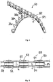
- FIG. 4 shows a roller chain 50 engaged with a sprocket 10 with chain inner-link pairs 51 and outer chain-link pairs 52.
- the alternating thin and thick teeth 32a, 32b of the chainring 10 represent an already known solution for improving the chain guidance.
- the sprocket 10 rotates in the drive direction DD.
- chain 50 consists of inner chain links and chain outer plates.
- two opposing inner straps or outer straps form an inner strap pair 51 or outer strap pair 52.
- the inner straps and outer straps are hingedly connected in alternation with the chain bolts 53.
- chain rollers 54 are rotatably mounted.
- the inner chain links of a chain inner link pair 51 are arranged at an axial distance D1 to each other.
- the outer chain links of a Kettenau tolaschencrus 52 are arranged at an axial distance D2 to each other. The distance D2 between the chain outer plates is greater than the distance D1 between the chain inner plates.
- distances D1 and D2 define the engagement space for the teeth 32 of the sprocket 10.
- the axial widths of the teeth 32 of the sprocket 10 must be matched to the distances D1 and D2.
- D1 is 2.16mm and D2 is 3.65mm.
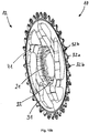
- FIG. 6a shows an external perspective view of an embodiment of a mounted on the right pedal crank 2 single chainring 10.
- the chainring 10 has at its radially inner region a hub portion 20 and at its radially outer portion a tooth portion 30 having a plurality of teeth 32. Between the hub region 20 and the tooth region 30, the connecting region 40 extends.
- the connecting portion 40 of this embodiment has a number of six arms 41 includes.
- the crank assembly consisting of the crank 2 and the chainring 10, rotates about the axis of rotation A in the drive direction DD.
- the arms 41 in the connecting region 40 are arranged relative to the pedal crank 2 so that the upper and lower dead center of the crank assembly is taken into account.
- the connection region 40 is free of arms 41 in the regions of the dead points, because only little force is transmitted from the crank 2 to the chainring 10 here.
- the design of the chainring 10 may be designed accordingly open and light in these areas.
- the chainring 10 In the areas outside of the dead centers, in which the pedal force acting on the crank 2 is high, the chainring 10, in particular the connecting region 40, must be designed to be correspondingly stable. In each case three arms 41 are arranged in these two areas outside the dead centers. The arrangement shown of six arms 41 has proven to be a particularly stable and at the same time lightweight construction.
- the pedal force is transmitted to the hub portion 30 of the chainring 10 via the pedal crank 2. From here, the force is transmitted via the arms 41 on the tooth portion 30 and further on a chain, not shown here.
- the sections along the drawn lines AA and CC will be discussed below.
- FIG. 7 shows an enlarged sectional view through the pedal crank assembly FIG. 6b along the line AA.
- the chainring 10 has an outer side 11, which faces in the direction of the crank 2, and one of these opposite inner side 12.
- the regions 20, 30, 40 each have an axial inner plane 29, 39, 49 on the inner side 12 of the chainring 10, an axial Outer plane 27, 37, 47 on the outside 11 of the chainring 10 and an intermediate axial center plane 28, 38, 48 on.
- the inner planes 29, 39, 49 are defined in each case by the axially innermost surfaces of the respective area 20, 30, 40.
- the outer planes 27, 37, 47 are defined in each case by the axially outermost surfaces of the respective area 20, 30, 40.
- the corresponding center planes 28, 38, 48 are each in the middle in between (see also FIG. 9 ).
- the tooth region 30 is offset by a varying offset dimension O in relation to the hub region 20 inward (axial offset or also called offset).
- Measured from the outer tooth plane 37 to the Hub outer plane 27 on the outer side 11 of the sprocket 10 is the dimension O of the axial offset, for example, 6.15 mm.
- the overall axial width G of the chainring 10 is measured from the hub outer plane 27 to the connecting inner plane 49 and corresponds to the maximum width of the sprocket 10.
- the total width G is, for example, 10.9 mm.
- the material thickness of the profiled arm 41 is chosen as low as possible.
- the axial width G1 - measured from the hub outer plane 27 to the profile bottom 45 of the arm 41 - is for example 9.9 mm. That is, the material thickness of the arm 41 on the profile bottom 45 is only 1 mm, which is very low compared to the overall width G.
- the axial width G2 measured from the hub outer plane 27 to the tooth inner plane 39 is less than the overall axial width G.
- the axial width G2 is for example 9.75 mm.
- connection inner plane 49 extends axially further inside than the tooth inner plane 39.
- the connecting region 40 hangs inwardly in the axial direction over the tooth region 30.
- the axial overhang Ü inward in this example case is 1.15 mm (10.9 mm minus 9.75 mm) - cf.
- the hub outer plane 27 extends through the abutment surface 24 of the hub portion 20 for the crank 2.
- FIG. 8a shows an enlarged sectional view through the pedal crank assembly FIG. 6b along the line CC.
- the circled detail shows a cross section through the profiled arm 41 and is in FIG. 8b shown enlarged.
- the arm 41 has a thin-walled, U-shaped profile 42.
- the profile 42 has a first and second profile wall 43, 44, which are connected to a profile bottom 45.
- the material thickness P1, P2 of the profile walls 43, 44 and the material thickness P3 of the tread 45 are approximately equal.
- the material thickness of the profile 42 could be about 1 mm to 1.5 mm.
- the material thickness of the arm profile 42 is dimensioned small - cf. For this FIG. 9 ).
- the profile width VB of the arm 41 decreases in the direction of the outer ring 31 of the toothed region 30. Due to the larger lever arm or the greater distance to the tooth region 30, where the chain forces attack, the cross section of the arms 41 in the hub region 20 must be sized larger than in the direction of the tooth region 30. In addition, the profiled arms 41 act in the drive direction DD as pressure rods , The profile thickness PD of the arm 41 is designed according to the stiffness requirements in the drive direction.
- FIG. 9 shows a further section through the crank assembly FIG. 6b ,
- the maximum axial widths NB, VB, ZB, measured from the respective inner plane 29, 39, 49 to the respective outer plane 27, 37, 47 are shown for the regions 20, 30, 40.
- the middle planes 28, 38, 48 are drawn between the respective inner and outer planes as dashed lines.
- the hub outer plane 27 lies in the axial direction A farther outward than the connecting outer plane 47 and the tooth outer plane 37.
- the connecting outer plane 47 lies axially further outward than the tooth outer plane 37.
- the inner hub plane 29 lies in the axial direction A farther outward than the inner tooth plane 39 and the connecting inner plane 49.
- the connection inner plane 49 lies axially further inwardly than the tooth inner plane 39. This produces the axial overhang Ü in the connection region 40. Measured from the connection inner plane 49 to the tooth center plane 38, the overhang is indicated as Ü1.
- the tooth center plane 38 and the connecting medium plane 48 are close together. The closer the center planes 38, 48 are to each other, the more balanced the skew can be taken in both axial directions - both on the smallest pinion 62 outwards and on the largest pinion 61 inward. Compare to the skew FIG. 3 , Depending on the direction in which the center planes 38, 48 are offset from one another, the more the skew can be taken up in one or the other axial direction. In the case shown, the connecting plane 48 extends slightly to the outside axially offset from the tooth center plane 38. This arrangement allows the internal skew on the largest pinion 61st which is most pronounced in sprocket assemblies with an increased number of pinions.
- the hub portion 20 has an axial width NB which is dimensioned from the hub outer plane 27 to the hub inner plane 29.
- the connection region 40 has a maximum axial width VB, which is dimensioned from the connection outer plane 47 to the connection inner plane 49.
- the tooth region 30 has a maximum axial width ZB, which is dimensioned from the outer tooth plane 37 to the inner tooth plane 39, and in this case corresponds to the tooth width Z1 of the thick tooth 32b.
- the axial width VB in the connection region 40 is particularly large in order to increase the rigidity.
- the connection region 40 extends in the axial direction even beyond the tooth inner plane 39 by the overhang dimension Ü.
- the axial width VB in the connection region 40 is dimensioned significantly greater than the axial width NB, ZB of the hub region 20 and the tooth region 30.
- the material thickness P of the arm profile 42 in the connection region 40 is chosen as low as possible in order to keep the weight low.
- the axial offset O1 of the toothed area 30 relative to the hub region 20, alternatively from the hub outer plane 27 to the tooth middle plane 38, is measured.
- the overhang U1 of the connection region 40 can be dimensioned from the connection inner plane 49 to the tooth middle plane 38.
- the dimensions O1 and Ü1 increase in relation to the dimensions O and Ü accordingly by half a tooth width.
- FIGS. 10a to 10e the chain ring 10 is shown in different views.
- the hub region 20, the connection region 40 and the tooth region 30 are lined up.
- the connecting portion 40 connects the hub portion 20 with the tooth portion 30.
- the hub portion 20 has at its radially inner end an inner profile 21 for transmitting torque from the crank to the sprocket 10.
- the tooth portion 30 has a plurality of teeth 32 at the radially outer end of the chainring 10.
- an even number of 36 teeth is arranged, which comprises a first group of teeth 32a and a second group of teeth 32b.
- the teeth 32a of the first group are in the axial direction formed narrower than the teeth 32b of the second group.
- the wide teeth 32b are sized to be suitable only for engagement with outer chain pair pairs 52.
- the narrow teeth 32a are correspondingly narrower and therefore also suitable for engagement in inner link pairs 51.
- the surfaces of the thick teeth 32b lying in the axial direction A on the inside define the tooth inner plane 39.
- the connecting portion 40 is formed by the arms 41.
- the arms 41 connect the hub portion 20 to the tooth portion 30.
- the space between the arms 41 is free of material to save weight. More specifically, the arms 41 extend between the inner race 22 of the boss portion 20 and an outer race 31 of the tooth portion 30.
- the arms 41 extend from the boss portion 20 toward the tooth portion 30 both in width (in the axial direction) and in thickness.
- the inner ring 22 of the hub portion 20 is disposed adjacent to the inner profile 21.
- the outer ring 31 of the tooth portion 30 is disposed radially inside the teeth 32.
- FIG. 10c shows the outer side 11 of the chainring 10 with the outwardly open U-shaped profile 42 of the six arms 41st
- FIG. 10d shows the inside 12 of the chainring 10th
- FIG. 10d shows a plan view of the chainring 10 with the areas 20, 30, 40th
- the chainrings 10 shown here are circular. However, it would also be possible to form the chainring not circular, but for example oval. Such oval chainrings minimize the less effective areas or dead centers of the crank assembly.
- the inventive design of the Bonding area is also applicable to such oval chainrings to increase the rigidity.
- the Figures 11a and 11b show an outer and an inner view of an enlarged partial section of the sprocket 10. Between each two adjacent teeth 32, a tooth base 35 is arranged. The root diameter 36 runs tangentially to the tooth roots 35.
- the thick teeth 32b of the second tooth group have thickenings 34.
- the thin teeth 32a are free of thickening. These thickenings 34 extend in the radial direction from the tooth tip 33 via the tooth root to beyond the root diameter 36. In other words, the thickenings 34 of the thick teeth extend 32b in the radial direction to below the tooth base 35. This compared to known designs in the radial direction significantly longer formed thickening 34 and the material thus obtained makes the tooth 32b more stable. As is clear from the FIGS.
- the thickening 34 is equally formed on the outside 11 and on the inside 12 of the sprocket 10 and the tooth 32b and thus extends on both sides of the tooth tip 33 to below the Wegnikischen messrs 36.
- the remaining material in the teeth 32 and the outer ring 31 can be removed, for example, by milling to the extent of the narrow teeth 32 a. This further saves weight.
- the chain ring 10 can be made of aluminum by machining processing, for example by milling precise and easy.
- the cross-sectional enlargement of the profile arms 41 in the connection region 40 beyond the tooth inner plane 39, allows a particularly low material thickness of the profile with sufficient rigidity.
- the chain ring 10 is sufficiently stable and lightweight as possible.
Landscapes
- Engineering & Computer Science (AREA)
- Mechanical Engineering (AREA)
- Chemical & Material Sciences (AREA)
- Combustion & Propulsion (AREA)
- Transportation (AREA)
- General Engineering & Computer Science (AREA)
- Gears, Cams (AREA)
- Valve-Gear Or Valve Arrangements (AREA)
- Devices For Conveying Motion By Means Of Endless Flexible Members (AREA)
Applications Claiming Priority (1)
| Application Number | Priority Date | Filing Date | Title |
|---|---|---|---|
| DE102017012035.8A DE102017012035A1 (de) | 2017-12-22 | 2017-12-22 | Einfach-Kettenrad |
Publications (3)
| Publication Number | Publication Date |
|---|---|
| EP3501962A2 true EP3501962A2 (fr) | 2019-06-26 |
| EP3501962A3 EP3501962A3 (fr) | 2019-09-11 |
| EP3501962B1 EP3501962B1 (fr) | 2022-07-13 |
Family
ID=64362292
Family Applications (1)
| Application Number | Title | Priority Date | Filing Date |
|---|---|---|---|
| EP18000906.0A Active EP3501962B1 (fr) | 2017-12-22 | 2018-11-16 | Roue dentée simple |
Country Status (5)
| Country | Link |
|---|---|
| US (1) | US11378171B2 (fr) |
| EP (1) | EP3501962B1 (fr) |
| CN (1) | CN109955997B (fr) |
| DE (1) | DE102017012035A1 (fr) |
| TW (1) | TWI791700B (fr) |
Families Citing this family (7)
| Publication number | Priority date | Publication date | Assignee | Title |
|---|---|---|---|---|
| DE102020102460A1 (de) * | 2020-01-31 | 2021-08-05 | MIRANDA & IRMÃO, LDª | Tretkurbelantrieb mit einer Tretkurbel und einem Kettenblatt sowie Verfahren zur Herstellung eines derartigen Tretkurbelantriebs |
| DE102020201889A1 (de) | 2020-02-14 | 2021-08-19 | Sram Deutschland Gmbh | Ritzel für einen Fahrrad-Antrieb |
| TWI726676B (zh) * | 2020-04-09 | 2021-05-01 | 傳誠技研有限公司 | 自行車鏈輪 |
| ES2982767T3 (es) * | 2022-03-03 | 2024-10-17 | Marcin Golec | Un plato de bicicleta mejorado y una bicicleta que comprende el plato de bicicleta |
| US12392403B2 (en) * | 2022-05-16 | 2025-08-19 | Wick Werks Llc | Bicycle chainring with offset and full wide teeth |
| DE102023115800B3 (de) * | 2023-06-16 | 2024-06-27 | Miranda & Irmão Lda. | Antriebssystem mit einer antriebswelle und einem kettenblatt |
| TWD232927S (zh) * | 2023-09-25 | 2024-08-11 | 桂盟企業股份有限公司 臺南市新化區中山路41號 (中華民國) | 齒盤的部分 |
Family Cites Families (43)
| Publication number | Priority date | Publication date | Assignee | Title |
|---|---|---|---|---|
| US6273836B1 (en) * | 2000-02-11 | 2001-08-14 | Spencer J. Thompson | Chain sprocket with axial stiffeners |
| US6475110B1 (en) * | 2000-03-17 | 2002-11-05 | Shimano Inc. | Bicycle front chainwheel assembly |
| US20060094550A1 (en) * | 2004-11-01 | 2006-05-04 | Shimano Inc. | Bicycle crankset |
| JP2007071302A (ja) * | 2005-09-07 | 2007-03-22 | Tsubakimoto Chain Co | 突起を有する焼結製スプロケット |
| US7753815B2 (en) * | 2007-01-19 | 2010-07-13 | Shimano Components (Malaysia) Sdn. Bhd. | Bicycle chain wheel assembly |
| US9062758B2 (en) * | 2011-12-06 | 2015-06-23 | Sram, Llc | Chainring |
| US9182027B2 (en) * | 2011-12-06 | 2015-11-10 | Sram, Llc | Chainring |
| ITMI20121481A1 (it) * | 2012-09-05 | 2014-03-06 | Angelo Morelli | Pedaliera per bicicletta |
| US9440706B2 (en) * | 2013-05-07 | 2016-09-13 | Shimano Inc. | Bicycle sprocket |
| DE102013009492B4 (de) * | 2013-06-05 | 2023-10-19 | Sram Deutschland Gmbh | Kettenring |
| US9297452B2 (en) * | 2013-10-01 | 2016-03-29 | Shimano Inc. | Bicycle sprocket |
| US9086138B1 (en) * | 2014-01-14 | 2015-07-21 | Shimano Inc. | Bicycle sprocket |
| US9302736B2 (en) * | 2014-02-05 | 2016-04-05 | Shimano Inc. | Bicycle sprocket |
| US9394987B2 (en) * | 2014-02-10 | 2016-07-19 | Wolf Tooth Components, LLC | Sprocket |
| US9394986B2 (en) * | 2014-02-10 | 2016-07-19 | Wolf Tooth Components, LLC | Sprocket |
| WO2015131023A1 (fr) * | 2014-02-27 | 2015-09-03 | Eko Sport, Inc. | Plateau à dents alternées |
| US9581231B2 (en) * | 2014-04-08 | 2017-02-28 | Wolf Tooth Components, LLC | Sprocket |
| US9625027B2 (en) * | 2014-04-08 | 2017-04-18 | Wolf Tooth Components, LLC | Sprocket |
| US9404565B2 (en) * | 2014-04-08 | 2016-08-02 | Wolf Tooth Components, LLC | Sprocket |
| US9964196B2 (en) * | 2014-05-20 | 2018-05-08 | Shimano Inc. | Bicycle sprocket |
| JP6455758B2 (ja) * | 2015-02-14 | 2019-01-23 | 陽一郎 濱元 | 回転伝達機構及びそれを備えた自転車 |
| US20160208903A1 (en) * | 2015-03-25 | 2016-07-21 | Wick Werks, LLC | Chainrings with Alternating Tooth Thickness Offset |
| WO2016168078A1 (fr) * | 2015-04-13 | 2016-10-20 | Eko Sport, Inc. | Plateau de chaîne muni de dents latéralement opposées venant en prise avec une chaîne d'entraînement |
| US9540070B2 (en) * | 2015-05-27 | 2017-01-10 | Shimano Inc. | Bicycle sprocket and bicycle crank assembly |
| DE202015004263U1 (de) * | 2015-06-16 | 2016-09-19 | Shimano Inc. | Fahrradkurbeltriebanordnung |
| DE102015016263A1 (de) * | 2015-12-15 | 2017-06-22 | Sram Deutschland Gmbh | Kettenring |
| US10549816B2 (en) * | 2016-02-26 | 2020-02-04 | Shimano Inc. | Bicycle sprocket and bicycle sprocket assembly |
| CN112517887A (zh) * | 2016-04-11 | 2021-03-19 | 福克斯制造有限公司 | 用于形成自行车前链轮组件的方法 |
| TWM535201U (zh) * | 2016-05-27 | 2017-01-11 | 島野股份有限公司 | 自行車用鏈輪、及自行車用鏈輪組裝體 |
| US9963196B2 (en) * | 2016-06-14 | 2018-05-08 | Shimano Inc. | Bicycle sprocket |
| US10359106B2 (en) * | 2016-06-24 | 2019-07-23 | Shimano Inc. | Bicycle sprocket and bicycle sprocket assembly |
| US10247291B2 (en) * | 2016-06-24 | 2019-04-02 | Shimano Inc. | Bicycle sprocket and bicycle sprocket assembly |
| US10377445B2 (en) * | 2016-09-20 | 2019-08-13 | Shimano Inc. | Bicycle front sprocket assembly |
| US10507888B2 (en) * | 2016-11-10 | 2019-12-17 | Shimano Inc. | Bicycle crank assembly and bicycle sprocket assembly |
| US10093389B2 (en) * | 2016-11-16 | 2018-10-09 | Shimano Inc. | Bicycle front sprocket, bicycle crank assembly, and bicycle drive train |
| US10407127B2 (en) * | 2016-11-24 | 2019-09-10 | Shimano Inc. | Bicycle sprocket |
| US10295041B2 (en) * | 2016-12-26 | 2019-05-21 | Shimano Inc. | Bicycle sprocket and bicycle sprocket assembly |
| US10378637B2 (en) * | 2017-01-19 | 2019-08-13 | Shimano Inc. | Bicycle sprocket |
| US10309515B2 (en) * | 2017-04-17 | 2019-06-04 | Shimano Inc. | Bicycle rear sprocket |
| US10550925B2 (en) * | 2017-06-02 | 2020-02-04 | Shimano Inc. | Bicycle sprocket |
| US10981626B2 (en) * | 2018-03-20 | 2021-04-20 | Sram Deutschland Gmbh | Drive arrangement for a bicycle |
| US11292555B2 (en) * | 2018-08-01 | 2022-04-05 | Shimano Inc. | Bicycle sprocket |
| US11680633B2 (en) * | 2019-02-08 | 2023-06-20 | Fox Factory, Inc. | Chainring |
-
2017
- 2017-12-22 DE DE102017012035.8A patent/DE102017012035A1/de not_active Withdrawn
-
2018
- 2018-11-16 EP EP18000906.0A patent/EP3501962B1/fr active Active
- 2018-12-05 TW TW107143747A patent/TWI791700B/zh active
- 2018-12-20 CN CN201811577936.5A patent/CN109955997B/zh active Active
- 2018-12-20 US US16/227,208 patent/US11378171B2/en active Active
Non-Patent Citations (1)
| Title |
|---|
| None |
Also Published As
| Publication number | Publication date |
|---|---|
| DE102017012035A1 (de) | 2019-06-27 |
| EP3501962A3 (fr) | 2019-09-11 |
| TWI791700B (zh) | 2023-02-11 |
| US20190195331A1 (en) | 2019-06-27 |
| CN109955997A (zh) | 2019-07-02 |
| CN109955997B (zh) | 2022-03-08 |
| EP3501962B1 (fr) | 2022-07-13 |
| US11378171B2 (en) | 2022-07-05 |
| TW201930139A (zh) | 2019-08-01 |
Similar Documents
| Publication | Publication Date | Title |
|---|---|---|
| EP3501962B1 (fr) | Roue dentée simple | |
| EP2497705B1 (fr) | Unité d'entraînement sur la roue arrière d'un vélo | |
| EP3093227B1 (fr) | Pignon de roue arrière de bicyclette | |
| DE102012023819B4 (de) | Kettenring | |
| EP3309052B1 (fr) | Dispositif à plusieurs pignons et entraînement par roue porteuse doté d'un tel dispositif à plusieurs pignons | |
| EP2810864B1 (fr) | Plateau | |
| DE102010027228B4 (de) | Mehrfach-Ritzelanordnung für Fahrräder | |
| EP3181439B1 (fr) | Anneau pour fil de chaine | |
| EP3339158B1 (fr) | Pignon, dispositif à plusieurs pignons et entraînement par roue porteuse doté d'un tel dispositif à plusieurs pignons | |
| EP3009339A1 (fr) | Systeme de roue d'entrainement multiple pour un moyeu de roue arriere | |
| DE102015005454A1 (de) | Fahrradkette | |
| DE102015004717A1 (de) | Fahrradkette | |
| EP3450297A1 (fr) | Support de roue à chaîne et dispositif de roue à chaînes multiples | |
| DE102007045424A1 (de) | Mehrfachkettenradeinheit für Fahrräder | |
| DE102018107642A1 (de) | Riementrieb | |
| EP3318335B1 (fr) | Chaînes à rouleau pour cycle | |
| DE102015000474A1 (de) | Fahrradkettenblatt | |
| DE202014005224U1 (de) | Fahrradkette | |
| EP3141776B1 (fr) | Attache interieure pour chaine a rouleaux | |
| DE102015017526B4 (de) | Fahrrad-Hinterrad-Ritzelanordnung |
Legal Events
| Date | Code | Title | Description |
|---|---|---|---|
| PUAI | Public reference made under article 153(3) epc to a published international application that has entered the european phase |
Free format text: ORIGINAL CODE: 0009012 |
|
| STAA | Information on the status of an ep patent application or granted ep patent |
Free format text: STATUS: THE APPLICATION HAS BEEN PUBLISHED |
|
| AK | Designated contracting states |
Kind code of ref document: A2 Designated state(s): AL AT BE BG CH CY CZ DE DK EE ES FI FR GB GR HR HU IE IS IT LI LT LU LV MC MK MT NL NO PL PT RO RS SE SI SK SM TR |
|
| AX | Request for extension of the european patent |
Extension state: BA ME |
|
| PUAL | Search report despatched |
Free format text: ORIGINAL CODE: 0009013 |
|
| AK | Designated contracting states |
Kind code of ref document: A3 Designated state(s): AL AT BE BG CH CY CZ DE DK EE ES FI FR GB GR HR HU IE IS IT LI LT LU LV MC MK MT NL NO PL PT RO RS SE SI SK SM TR |
|
| AX | Request for extension of the european patent |
Extension state: BA ME |
|
| RIC1 | Information provided on ipc code assigned before grant |
Ipc: B62M 9/02 20060101ALI20190808BHEP Ipc: B62M 9/10 20060101AFI20190808BHEP |
|
| RIN1 | Information on inventor provided before grant (corrected) |
Inventor name: HANKE, JOACHIM |
|
| STAA | Information on the status of an ep patent application or granted ep patent |
Free format text: STATUS: REQUEST FOR EXAMINATION WAS MADE |
|
| 17P | Request for examination filed |
Effective date: 20200213 |
|
| STAA | Information on the status of an ep patent application or granted ep patent |
Free format text: STATUS: EXAMINATION IS IN PROGRESS |
|
| 17Q | First examination report despatched |
Effective date: 20210412 |
|
| REG | Reference to a national code |
Ref country code: DE Ref legal event code: R079 Ref document number: 502018010123 Country of ref document: DE Free format text: PREVIOUS MAIN CLASS: B62M0009100000 Ipc: F16H0055300000 |
|
| RIC1 | Information provided on ipc code assigned before grant |
Ipc: B62M 9/02 20060101ALI20211130BHEP Ipc: B62M 9/10 20060101ALI20211130BHEP Ipc: F16H 55/30 20060101AFI20211130BHEP |
|
| GRAP | Despatch of communication of intention to grant a patent |
Free format text: ORIGINAL CODE: EPIDOSNIGR1 |
|
| STAA | Information on the status of an ep patent application or granted ep patent |
Free format text: STATUS: GRANT OF PATENT IS INTENDED |
|
| INTG | Intention to grant announced |
Effective date: 20220209 |
|
| GRAS | Grant fee paid |
Free format text: ORIGINAL CODE: EPIDOSNIGR3 |
|
| GRAA | (expected) grant |
Free format text: ORIGINAL CODE: 0009210 |
|
| STAA | Information on the status of an ep patent application or granted ep patent |
Free format text: STATUS: THE PATENT HAS BEEN GRANTED |
|
| AK | Designated contracting states |
Kind code of ref document: B1 Designated state(s): AL AT BE BG CH CY CZ DE DK EE ES FI FR GB GR HR HU IE IS IT LI LT LU LV MC MK MT NL NO PL PT RO RS SE SI SK SM TR |
|
| REG | Reference to a national code |
Ref country code: CH Ref legal event code: EP |
|
| REG | Reference to a national code |
Ref country code: DE Ref legal event code: R096 Ref document number: 502018010123 Country of ref document: DE |
|
| REG | Reference to a national code |
Ref country code: AT Ref legal event code: REF Ref document number: 1504442 Country of ref document: AT Kind code of ref document: T Effective date: 20220815 |
|
| REG | Reference to a national code |
Ref country code: IE Ref legal event code: FG4D Free format text: LANGUAGE OF EP DOCUMENT: GERMAN |
|
| REG | Reference to a national code |
Ref country code: NL Ref legal event code: FP |
|
| REG | Reference to a national code |
Ref country code: LT Ref legal event code: MG9D |
|
| PG25 | Lapsed in a contracting state [announced via postgrant information from national office to epo] |
Ref country code: SE Free format text: LAPSE BECAUSE OF FAILURE TO SUBMIT A TRANSLATION OF THE DESCRIPTION OR TO PAY THE FEE WITHIN THE PRESCRIBED TIME-LIMIT Effective date: 20220713 Ref country code: RS Free format text: LAPSE BECAUSE OF FAILURE TO SUBMIT A TRANSLATION OF THE DESCRIPTION OR TO PAY THE FEE WITHIN THE PRESCRIBED TIME-LIMIT Effective date: 20220713 Ref country code: PT Free format text: LAPSE BECAUSE OF FAILURE TO SUBMIT A TRANSLATION OF THE DESCRIPTION OR TO PAY THE FEE WITHIN THE PRESCRIBED TIME-LIMIT Effective date: 20221114 Ref country code: NO Free format text: LAPSE BECAUSE OF FAILURE TO SUBMIT A TRANSLATION OF THE DESCRIPTION OR TO PAY THE FEE WITHIN THE PRESCRIBED TIME-LIMIT Effective date: 20221013 Ref country code: LV Free format text: LAPSE BECAUSE OF FAILURE TO SUBMIT A TRANSLATION OF THE DESCRIPTION OR TO PAY THE FEE WITHIN THE PRESCRIBED TIME-LIMIT Effective date: 20220713 Ref country code: LT Free format text: LAPSE BECAUSE OF FAILURE TO SUBMIT A TRANSLATION OF THE DESCRIPTION OR TO PAY THE FEE WITHIN THE PRESCRIBED TIME-LIMIT Effective date: 20220713 Ref country code: FI Free format text: LAPSE BECAUSE OF FAILURE TO SUBMIT A TRANSLATION OF THE DESCRIPTION OR TO PAY THE FEE WITHIN THE PRESCRIBED TIME-LIMIT Effective date: 20220713 Ref country code: ES Free format text: LAPSE BECAUSE OF FAILURE TO SUBMIT A TRANSLATION OF THE DESCRIPTION OR TO PAY THE FEE WITHIN THE PRESCRIBED TIME-LIMIT Effective date: 20220713 |
|
| PG25 | Lapsed in a contracting state [announced via postgrant information from national office to epo] |
Ref country code: PL Free format text: LAPSE BECAUSE OF FAILURE TO SUBMIT A TRANSLATION OF THE DESCRIPTION OR TO PAY THE FEE WITHIN THE PRESCRIBED TIME-LIMIT Effective date: 20220713 Ref country code: IS Free format text: LAPSE BECAUSE OF FAILURE TO SUBMIT A TRANSLATION OF THE DESCRIPTION OR TO PAY THE FEE WITHIN THE PRESCRIBED TIME-LIMIT Effective date: 20221113 Ref country code: HR Free format text: LAPSE BECAUSE OF FAILURE TO SUBMIT A TRANSLATION OF THE DESCRIPTION OR TO PAY THE FEE WITHIN THE PRESCRIBED TIME-LIMIT Effective date: 20220713 Ref country code: GR Free format text: LAPSE BECAUSE OF FAILURE TO SUBMIT A TRANSLATION OF THE DESCRIPTION OR TO PAY THE FEE WITHIN THE PRESCRIBED TIME-LIMIT Effective date: 20221014 |
|
| REG | Reference to a national code |
Ref country code: DE Ref legal event code: R097 Ref document number: 502018010123 Country of ref document: DE |
|
| PG25 | Lapsed in a contracting state [announced via postgrant information from national office to epo] |
Ref country code: SM Free format text: LAPSE BECAUSE OF FAILURE TO SUBMIT A TRANSLATION OF THE DESCRIPTION OR TO PAY THE FEE WITHIN THE PRESCRIBED TIME-LIMIT Effective date: 20220713 Ref country code: RO Free format text: LAPSE BECAUSE OF FAILURE TO SUBMIT A TRANSLATION OF THE DESCRIPTION OR TO PAY THE FEE WITHIN THE PRESCRIBED TIME-LIMIT Effective date: 20220713 Ref country code: DK Free format text: LAPSE BECAUSE OF FAILURE TO SUBMIT A TRANSLATION OF THE DESCRIPTION OR TO PAY THE FEE WITHIN THE PRESCRIBED TIME-LIMIT Effective date: 20220713 Ref country code: CZ Free format text: LAPSE BECAUSE OF FAILURE TO SUBMIT A TRANSLATION OF THE DESCRIPTION OR TO PAY THE FEE WITHIN THE PRESCRIBED TIME-LIMIT Effective date: 20220713 |
|
| PLBE | No opposition filed within time limit |
Free format text: ORIGINAL CODE: 0009261 |
|
| STAA | Information on the status of an ep patent application or granted ep patent |
Free format text: STATUS: NO OPPOSITION FILED WITHIN TIME LIMIT |
|
| PG25 | Lapsed in a contracting state [announced via postgrant information from national office to epo] |
Ref country code: SK Free format text: LAPSE BECAUSE OF FAILURE TO SUBMIT A TRANSLATION OF THE DESCRIPTION OR TO PAY THE FEE WITHIN THE PRESCRIBED TIME-LIMIT Effective date: 20220713 Ref country code: EE Free format text: LAPSE BECAUSE OF FAILURE TO SUBMIT A TRANSLATION OF THE DESCRIPTION OR TO PAY THE FEE WITHIN THE PRESCRIBED TIME-LIMIT Effective date: 20220713 |
|
| 26N | No opposition filed |
Effective date: 20230414 |
|
| P01 | Opt-out of the competence of the unified patent court (upc) registered |
Effective date: 20230523 |
|
| PG25 | Lapsed in a contracting state [announced via postgrant information from national office to epo] |
Ref country code: MC Free format text: LAPSE BECAUSE OF FAILURE TO SUBMIT A TRANSLATION OF THE DESCRIPTION OR TO PAY THE FEE WITHIN THE PRESCRIBED TIME-LIMIT Effective date: 20220713 Ref country code: AL Free format text: LAPSE BECAUSE OF FAILURE TO SUBMIT A TRANSLATION OF THE DESCRIPTION OR TO PAY THE FEE WITHIN THE PRESCRIBED TIME-LIMIT Effective date: 20220713 |
|
| REG | Reference to a national code |
Ref country code: CH Ref legal event code: PL |
|
| GBPC | Gb: european patent ceased through non-payment of renewal fee |
Effective date: 20221116 |
|
| REG | Reference to a national code |
Ref country code: BE Ref legal event code: MM Effective date: 20221130 |
|
| PG25 | Lapsed in a contracting state [announced via postgrant information from national office to epo] |
Ref country code: LI Free format text: LAPSE BECAUSE OF NON-PAYMENT OF DUE FEES Effective date: 20221130 Ref country code: CH Free format text: LAPSE BECAUSE OF NON-PAYMENT OF DUE FEES Effective date: 20221130 |
|
| PG25 | Lapsed in a contracting state [announced via postgrant information from national office to epo] |
Ref country code: SI Free format text: LAPSE BECAUSE OF FAILURE TO SUBMIT A TRANSLATION OF THE DESCRIPTION OR TO PAY THE FEE WITHIN THE PRESCRIBED TIME-LIMIT Effective date: 20220713 Ref country code: LU Free format text: LAPSE BECAUSE OF NON-PAYMENT OF DUE FEES Effective date: 20221116 |
|
| PG25 | Lapsed in a contracting state [announced via postgrant information from national office to epo] |
Ref country code: IE Free format text: LAPSE BECAUSE OF NON-PAYMENT OF DUE FEES Effective date: 20221116 Ref country code: GB Free format text: LAPSE BECAUSE OF NON-PAYMENT OF DUE FEES Effective date: 20221116 |
|
| PG25 | Lapsed in a contracting state [announced via postgrant information from national office to epo] |
Ref country code: BE Free format text: LAPSE BECAUSE OF NON-PAYMENT OF DUE FEES Effective date: 20221130 |
|
| PGFP | Annual fee paid to national office [announced via postgrant information from national office to epo] |
Ref country code: NL Payment date: 20231120 Year of fee payment: 6 |
|
| PG25 | Lapsed in a contracting state [announced via postgrant information from national office to epo] |
Ref country code: IT Free format text: LAPSE BECAUSE OF FAILURE TO SUBMIT A TRANSLATION OF THE DESCRIPTION OR TO PAY THE FEE WITHIN THE PRESCRIBED TIME-LIMIT Effective date: 20220713 |
|
| PGFP | Annual fee paid to national office [announced via postgrant information from national office to epo] |
Ref country code: FR Payment date: 20231120 Year of fee payment: 6 |
|
| PG25 | Lapsed in a contracting state [announced via postgrant information from national office to epo] |
Ref country code: HU Free format text: LAPSE BECAUSE OF FAILURE TO SUBMIT A TRANSLATION OF THE DESCRIPTION OR TO PAY THE FEE WITHIN THE PRESCRIBED TIME-LIMIT; INVALID AB INITIO Effective date: 20181116 |
|
| PG25 | Lapsed in a contracting state [announced via postgrant information from national office to epo] |
Ref country code: CY Free format text: LAPSE BECAUSE OF FAILURE TO SUBMIT A TRANSLATION OF THE DESCRIPTION OR TO PAY THE FEE WITHIN THE PRESCRIBED TIME-LIMIT Effective date: 20220713 |
|
| PG25 | Lapsed in a contracting state [announced via postgrant information from national office to epo] |
Ref country code: MK Free format text: LAPSE BECAUSE OF FAILURE TO SUBMIT A TRANSLATION OF THE DESCRIPTION OR TO PAY THE FEE WITHIN THE PRESCRIBED TIME-LIMIT Effective date: 20220713 |
|
| PG25 | Lapsed in a contracting state [announced via postgrant information from national office to epo] |
Ref country code: TR Free format text: LAPSE BECAUSE OF FAILURE TO SUBMIT A TRANSLATION OF THE DESCRIPTION OR TO PAY THE FEE WITHIN THE PRESCRIBED TIME-LIMIT Effective date: 20220713 |
|
| PG25 | Lapsed in a contracting state [announced via postgrant information from national office to epo] |
Ref country code: BG Free format text: LAPSE BECAUSE OF FAILURE TO SUBMIT A TRANSLATION OF THE DESCRIPTION OR TO PAY THE FEE WITHIN THE PRESCRIBED TIME-LIMIT Effective date: 20220713 |
|
| PG25 | Lapsed in a contracting state [announced via postgrant information from national office to epo] |
Ref country code: MT Free format text: LAPSE BECAUSE OF FAILURE TO SUBMIT A TRANSLATION OF THE DESCRIPTION OR TO PAY THE FEE WITHIN THE PRESCRIBED TIME-LIMIT Effective date: 20220713 |
|
| REG | Reference to a national code |
Ref country code: AT Ref legal event code: MM01 Ref document number: 1504442 Country of ref document: AT Kind code of ref document: T Effective date: 20231116 |
|
| PG25 | Lapsed in a contracting state [announced via postgrant information from national office to epo] |
Ref country code: AT Free format text: LAPSE BECAUSE OF NON-PAYMENT OF DUE FEES Effective date: 20231116 |
|
| PG25 | Lapsed in a contracting state [announced via postgrant information from national office to epo] |
Ref country code: AT Free format text: LAPSE BECAUSE OF NON-PAYMENT OF DUE FEES Effective date: 20231116 |
|
| REG | Reference to a national code |
Ref country code: NL Ref legal event code: MM Effective date: 20241201 |
|
| PG25 | Lapsed in a contracting state [announced via postgrant information from national office to epo] |
Ref country code: NL Free format text: LAPSE BECAUSE OF NON-PAYMENT OF DUE FEES Effective date: 20241201 |
|
| PG25 | Lapsed in a contracting state [announced via postgrant information from national office to epo] |
Ref country code: FR Free format text: LAPSE BECAUSE OF NON-PAYMENT OF DUE FEES Effective date: 20241130 |
|
| PGFP | Annual fee paid to national office [announced via postgrant information from national office to epo] |
Ref country code: DE Payment date: 20251113 Year of fee payment: 8 |
|
| PGFP | Annual fee paid to national office [announced via postgrant information from national office to epo] |
Ref country code: AT Payment date: 20260410 Year of fee payment: 5 |