EP3503311B1 - Profilé de guidage de courant - Google Patents
Profilé de guidage de courant Download PDFInfo
- Publication number
- EP3503311B1 EP3503311B1 EP18211032.0A EP18211032A EP3503311B1 EP 3503311 B1 EP3503311 B1 EP 3503311B1 EP 18211032 A EP18211032 A EP 18211032A EP 3503311 B1 EP3503311 B1 EP 3503311B1
- Authority
- EP
- European Patent Office
- Prior art keywords
- bridging element
- profile
- profile elements
- grooves
- current
- Prior art date
- Legal status (The legal status is an assumption and is not a legal conclusion. Google has not performed a legal analysis and makes no representation as to the accuracy of the status listed.)
- Active
Links
Images



Classifications
-
- H—ELECTRICITY
- H01—ELECTRIC ELEMENTS
- H01R—ELECTRICALLY-CONDUCTIVE CONNECTIONS; STRUCTURAL ASSOCIATIONS OF A PLURALITY OF MUTUALLY-INSULATED ELECTRICAL CONNECTING ELEMENTS; COUPLING DEVICES; CURRENT COLLECTORS
- H01R25/00—Coupling parts adapted for simultaneous co-operation with two or more identical counterparts, e.g. for distributing energy to two or more circuits
- H01R25/14—Rails or bus-bars constructed so that the counterparts can be connected thereto at any point along their length
- H01R25/145—Details, e.g. end pieces or joints
-
- H—ELECTRICITY
- H02—GENERATION; CONVERSION OR DISTRIBUTION OF ELECTRIC POWER
- H02G—INSTALLATION OF ELECTRIC CABLES OR LINES, OR OF COMBINED OPTICAL AND ELECTRIC CABLES OR LINES
- H02G5/00—Installations of bus-bars
- H02G5/002—Joints between bus-bars for compensating thermal expansion
-
- H—ELECTRICITY
- H02—GENERATION; CONVERSION OR DISTRIBUTION OF ELECTRIC POWER
- H02G—INSTALLATION OF ELECTRIC CABLES OR LINES, OR OF COMBINED OPTICAL AND ELECTRIC CABLES OR LINES
- H02G3/00—Installations of electric cables or lines or protective tubing therefor in or on buildings, equivalent structures or vehicles
- H02G3/02—Details
- H02G3/06—Joints for connecting lengths of protective tubing or channels, to each other or to casings, e.g. to distribution boxes; Ensuring electrical continuity in the joint
- H02G3/0608—Joints for connecting non cylindrical conduits, e.g. channels
-
- H—ELECTRICITY
- H02—GENERATION; CONVERSION OR DISTRIBUTION OF ELECTRIC POWER
- H02G—INSTALLATION OF ELECTRIC CABLES OR LINES, OR OF COMBINED OPTICAL AND ELECTRIC CABLES OR LINES
- H02G5/00—Installations of bus-bars
- H02G5/04—Partially-enclosed installations, e.g. in ducts and adapted for sliding or rolling current collection
Definitions
- the invention relates to a current-conducting profile according to the preamble of claim 1.
- EP 1 284 035 B1 discloses a busbar system for lights with a current conducting profile.
- wire holding elements are provided that have grooves for receiving electrical conductors. When the wire holding elements are inserted into one another, a connection area is created that can be contacted from the outside. Such a current conducting profile can be adapted to the corresponding application.
- a multi-pole connection line is known.
- a connector for electrically connecting two electrical contact lines is known.
- From the DE 20 2016 104 790 U1 a connector for end-side plugging onto a current-carrying profile is known.
- the object of the present invention is to create an improved current-carrying profile in which the changes in length can be compensated for by expanding the current-carrying profile and, at the same time, particularly simple assembly can be ensured.
- the bridging element be movably mountable on the profile elements, the bridging element being able to be arranged between the end faces of two adjacent profile elements.
- the grooves of the bridging element are aligned with the grooves of the profile elements arranged thereon.
- a compensation is provided in a simple manner, which prevents an expansion of the current-carrying profile, e.g. occurs through thermal expansion, compensated for and avoids an excessive gap between two profile elements in order to ensure safe handling.
- the electrical conductors can be inserted into the grooves of the profile elements and the grooves of the bridging element from the common side of the profile elements, towards which the grooves are open, and the common side of the bridging element, to which the grooves of the bridging element are opened .
- This allows a particularly simple assembly of the current-carrying profile.
- the profile elements can have fastening elements for fastening to a mounting rail. This allows identically structured profile elements to be strung together in a simple manner.
- the bridging element is designed as a separate component and is preferably not intended for attachment to the mounting rail, so that the bridging element has sufficient play between the end faces of the adjacent profile elements to compensate for expansion of the current-carrying profile or not to hinder the expansion of the current-carrying profile.
- the profile elements have an end projection, the bridging element being movably mountable on the end projections of the profile elements.
- the projections of the profile elements provide assembly locations for the bridging element, so that the bridging element only has to be placed on the projections between the profile elements.
- the bridging element can have coupling projections on the underside for movable mounting on the profile elements, the coupling projections dipping into recesses in the end projections of the profile elements.
- the bridging element has recesses, with coupling projections of the profile elements dip into the recesses of the bridging element.
- a bottom side is to be understood as the side facing away from the grooves.
- the profile elements and the bridging element can form a gap, the gap being arranged between the grooves of the profile elements and the grooves of the bridging element.
- the gap ensures sufficient operational reliability, since contact with the electrical conductors is prevented by a sufficiently narrow gap.
- the bridging element and / or the profile elements have stops to limit the gap between the bridging element and the profile element.
- the gap can be limited by stops in such a way that it is not possible for the operator to touch the electrical conductor.
- the gap is limited in such a way that it is not possible for the operator to reach into it. It is thus prevented that the bridging element only moves relatively in the direction of only one profile element and thus the gaps are more or less evenly widened or narrowed.
- the bridging element can be floatingly mounted on the profile elements.
- the bridging element and / or the profile elements can experience mechanical or thermal changes in length without them becoming warped.
- the bridging element has play in the direction of longitudinal extension, so that changes in length can be absorbed by the bridging element by shifting it in the longitudinal direction. This has the advantage that a cost-effective construction can be achieved which compensates for the expansion of the bridging element and the profile elements in the area of the play of the bearing with little effort.
- the grooves of the profile elements and the grooves of the bridging element for receiving electrical conductors can have different receiving planes. It is advantageous if the adjacent grooves of the profile elements and the adjacent grooves of the bridging element are each arranged offset in height to one another. In this way, the air gaps and creepage distances are further reduced increases the height offset.
- the height offset is the distance between the neighboring electrical conductors or the groove bases of neighboring grooves in the direction of immersion in a groove, viewed from the open top to the groove base.
- a first group of grooves can span a first level with their groove bottoms and a second group of grooves, which are each arranged between two grooves of the first group, can span a second level with their groove bottoms.
- the first and second levels are then offset in height relative to one another. This means that the grooves, viewed transversely to the direction of longitudinal extension of the profile element and the bridging element, are arranged alternately offset in height.
- the adjacent grooves are of different depths, so that the adjacent electrical conductors are arranged alternately offset in height.
- the bridging element can be connected to the profile elements via at least one predetermined breaking point, the predetermined breaking point being breakable under the action of force and connecting the bridging element to the profile elements.
- a current-carrying profile can be provided in a simple constructive manner which, under the action of force, e.g. an electrical conductor to be inserted into the grooves of the bridging element connects the bridging element with the profile elements, the predetermined breaking points breaking open.
- the predetermined breaking points are arranged on the upper and / or front side of the profile elements.
- the bridging element can be connected to the profile elements, so that assembly on the profile elements is facilitated after the predetermined breaking points of the bridging element have been broken.
- the predetermined breaking points break open by the action of a horizontal and / or vertical force.
- the predetermined breaking points of the current-carrying profile can be broken open and the bridging element can be connected to the profile elements. This can be done, for example, when inserting an electrical conductor into the grooves of the bridging element, when inserting the profile elements into the support rail under pressure or by inserting the profile elements.
- the predetermined breaking points can be provided in that the bridging element is integrally molded or injection-molded onto at least one of the two profile elements.
- a current-carrying profile can be provided at the same time, which provides a simple assembly of the bridging element on the profile elements.
- a mounting projection is provided on the end of the bridging element opposite the predetermined breaking points, which ensures that the bridging element is safely inserted into the opposing profile elements.
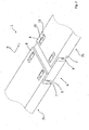
- Figure 1 shows a perspective view of a current-carrying profile 1 with two electrically insulating profile elements 2a, 2b.
- the profile elements 2a, 2b are shown reduced in length by being cut off along their longitudinal direction L.
- the profile elements 2a, 2b have a number of grooves 4a, 4b corresponding to the number of electrical conductors 3 to be received.
- Each groove 4a, 4b is delimited by a pair of groove walls 5, which extend in the longitudinal direction L of the respective profile element 2a, 2b and are arranged parallel to one another in a width direction B.
- the grooves 4a, 4b are designed in such a way that electrical conductors 3 can be inserted.
- the current-carrying profile 1 has a bridging element 6, the bridging element being arranged between the end faces 7 of the profile elements 2a, 2b, the bridging element having grooves 4c, 4d which are arranged parallel to one another in the direction of longitudinal extent L and in a widthwise direction B and which correspond to the grooves 4a, 4b of the profile elements 2a, 2b are arranged so that the grooves 4c, 4d of the bridging element 6 and the grooves 4a, 4b of the profile elements 2a, 2b form a common device for receiving electrical conductors 3.
- the bridging element 6 is movably supported on end projections 8 of the profile elements 2a, 2b.
- Grooves 4a, 4b arranged next to one another; 4c, 4d have a common groove side wall 5. It becomes clear that the grooves 4a, 4b; 4c, 4d are arranged alternately offset in height. In this case, a first group of grooves 4a, 4c lies in a common plane and a second group of grooves 4b, 4d in a further plane, the planes being arranged offset from one another in height and preferably aligned parallel to one another. The inserted electrical conductor 3 cannot be seen in the second level due to the height offset.
- FIG. 11 shows a perspective view of the underside of the current conducting profile 1 from FIG Figure 1 .
- the underside of the current-carrying profile 1 is the side facing away from the grooves 4a, 4b of the profile elements 2a, 2b and the grooves 4c, 4d of the bridging element 6.
- the bridging element 6 has coupling projections 10 which dip into recesses 11 on the end projections 8 of the profile elements 2a, 2b. It can be seen that the bridging element 6 is movably supported via four coupling projections 10 in two recesses 11 of the profile elements 2a, 2b between the end faces 7 and a change in length of the current-carrying profile 1 can thus be compensated for.
- the bridging element 6 has recesses 11 into which the coupling projections 10 of the profile elements 2a, 2b dip and thus a movable one Provide storage of the bridging element 6.
- the number of coupling projections 10 and the associated recesses 11 is not limited to this embodiment, but can vary depending on the application.
- FIG. 4 shows a perspective view of the underside of a current-carrying profile 1 from FIG Figure 1 in a sectional view. It becomes clear that the grooves 4a, 4b; 4c, 4d are arranged with their groove bottom 13 alternately vertically offset from one another. It can also be seen that the profile elements 2a, 2b have stops 12 within the recess 11, so that the dimensions of the gap between the profile elements 2a, 2b and the bridging element are limited. This ensures the safety of the operator.
- stops 12 are arranged on the bridging element 6.
- Figure 4 shows a schematic representation of a current-carrying profile 1 in a side view with two electrically insulating profile elements 2a, 2b.
- the profile elements 2a, 2b have latching elements 14 for attachment to a support rail.
- the bridging element 6 is connected to one of the profile elements 2a, 2b via at least one predetermined breaking point 15 on the upper side.
- the bridging element 6, however, has no latching elements 14, so that a movable mounting is ensured.
- a connection can take place, for example, via an injection molding process in the production of the current-carrying profile 1.
- a compact current-carrying profile 1 is provided by connecting the bridging element 6 to the profile elements 2a, 2b.
- the predetermined breaking points 15 can be broken open under the action of force, for example by inserting an electrical conductor into the grooves of the bridging element 6, so that the bridging element 6 is movably connected to the profile elements 2a, 2b.
- the bridging element 6 is preferably only connected to only one current-carrying profile 2a via a predetermined breaking point 15.
- a mounting projection can be provided on its free end facing the second current-carrying profile 2b 17 may be provided.
- the mounting projection 17 protrudes from the bridging element 6 in the direction of the dipping direction into the grooves 4a, 4b. In a pre-assembly position of the profile elements 2a, 2b, this assembly projection 17 protrudes into a corresponding recess on the second profile element 2b (see also FIG Figure 5 ).
- the bridging element 6 can be connected to at least one end face 7 of the profile elements 2a, 2b via predetermined breaking points and that these predetermined breaking points break open under the action of vertical force in the longitudinal direction of the current-carrying profile 1.
- FIG. 11 shows a schematic current-carrying profile in a sectional view AA from FIG Figure 4 .
- a single groove 4 of the bridging element 6 and the profile elements 2a, 2b is shown.
- An embodiment with grooves arranged next to one another is still conceivable. It becomes clear that after the predetermined breaking points 15 have been broken, the bridging element 6 dips precisely between the walls 16 of the profile elements 2a, 2b and provides a common receptacle for electrical conductors.
- the groove 4d of the bridging element 6 is aligned axially symmetrically with the groove 4b of the profile elements 2a, 2b, so that an electrical conductor can be inserted into the grooves 4b, 4d.
- FIG. 11 shows a schematic view of a current-carrying profile 1 after the predetermined breaking points 15 have been broken Figure 4 and 5 .
- the bridging element 6 is movably connected via the end projections 8 of the profile elements 2a, 2b. There is a gap 9 between the end faces 7 of the profile elements 2a, 2b and the end faces 7 of the bridging element 6.
- an electrical conductor 3 By inserting an electrical conductor 3 into the bridging element 6, the predetermined breaking points 15 were cut Figure 4 and Figure 5 broken up.
- the grooves 4a, 4b with the delimiting groove walls 5 of the profile elements 2a, 2b and the grooves 4c, 4d of the bridging element 6 thus form a common device for receiving the electrical conductor 3.
- the electrical conductor 3 can continue to be tapped via the gap 9 without endanger the safety of the operator. Any expansion of the current-carrying profile 1 is compensated for by the movable mounting of the bridging element 6 on the profile elements 2a, 2b, so that component stresses cannot lead to damage.
Landscapes
- Current-Collector Devices For Electrically Propelled Vehicles (AREA)
- Connector Housings Or Holding Contact Members (AREA)
- Train Traffic Observation, Control, And Security (AREA)
Claims (12)
- Profilé de conduction de courant (1), comprenant au moins deux éléments de profilé (2a, 2b) et un élément de pontage (6), les éléments de profilé (2a, 2b) présentant en parallèle côte à côte des rainures (4a, 4b) s'étendant dans une direction d'extension longitudinale (L) des éléments de profilé (2a, 2b) pour recevoir des conducteurs électriques, dans lequel les rainures (4a, 4b) sont délimitées par une paire de parois de rainure (5), présentent un fond de rainure (13) et sont ouvertes vers un côté commun de l'élément de profilé (2a, 2b), et dans lequel les éléments de profilé (2a, 2b) sont reliés l'un à l'autre par l'élément de pontage (6), dans lequel l'élément de pontage (6) présente des rainures (4c, 4d) disposées côte à côte dans la direction d'extension longitudinale (L) de l'élément de pontage (6), qui peuvent être disposées par rapport aux rainures (4a, 4b) des éléments de profilé (2a, 2b) de telle sorte que les rainures (4c, 4d) de l'élément de pontage (6) et les rainures (4a, 4b) des éléments de profilé (2a, 2b) forment un dispositif commun pour recevoir des conducteurs électriques (3), de telle sorte que les rainures (4c, 4d) de l'élément de pontage (6) sont délimitées par une paire de parois de rainure (5), présentent un fond de rainure (13) et sont ouvertes vers un côté commun de l'élément de pontage (6), dans lequel les rainures des éléments de profilé (2a, 2b) et les rainures de l'élément de pontage (6) sont ouvertes vers le même côté, l'élément de pontage (6) pouvant être monté mobile sur les éléments de profilé (2a,2b), l'élément de pontage (6) pouvant être disposé entre les faces frontales (7) de deux éléments de profilé (2a, 2b) voisins,
caractérisé en ce que les conducteurs électriques (3), depuis le côté commun des éléments de profilé (2a, 2b) vers lequel les rainures (4a, 4b) sont ouvertes, et depuis le côté commun de l'élément de pontage (6) vers lequel les rainures (4c, 4d) de l'élément de pontage (6) sont ouvertes, peuvent être insérés dans les rainures (4a, 4b) des éléments de profilé (2a, 2b) et dans les rainures (4c, 4d) de l'élément de pontage (6). - Profilé de conduction de courant (1) selon la revendication 1, caractérisé en ce que l'élément de pontage (6) peut être monté mobile sur au moins une saillie (8) côté extrémité des éléments de profilé (2a, 2b).
- Profilé de conduction de courant (1) selon la revendication 2, caractérisé en ce que l'élément de pontage (6) présente sur la face inférieure des saillies de couplage (10) pour le montage mobile sur les éléments de profilé (2a, 2b), les saillies de couplage (10) s'enfonçant dans des creux (11) des saillies côté extrémité (8) des éléments de profilé (2a, 2b) ou les éléments de profilé (2a, 2b) présentant des saillies de couplage (10), les saillies de couplage (10) s'enfonçant dans des creux (11) de l'élément de pontage (6).
- Profilé de conduction de courant (1) selon l'une quelconque des revendications précédentes, caractérisé en ce que les éléments de profilé (2a, 2b) et l'élément de pontage (6) forment un intervalle (9), l'intervalle (9) étant disposé entre les faces frontales (7) des éléments de profilé (2a, 2b) et les faces frontales (7) de l'élément de pontage (6).
- Profilé de conduction de courant (1) selon la revendication 4, caractérisé en ce que l'élément de pontage (6) et/ou les éléments de profilé (2a, 2b) présentent des butées (12) pour délimiter l'intervalle (9) entre les faces frontales (7) de l'élément de pontage (6) et les faces frontales (7) des éléments de profilé (2a, 2b).
- Profilé de conduction de courant (1) selon l'une quelconque des revendications précédentes, caractérisé en ce que l'élément de pontage (6) peut être monté flottant sur les éléments de profilé (2a, 2b).
- Profilé de conduction de courant (1) selon l'une quelconque des revendications précédentes, caractérisé en ce que des rainures (4a, 4b) adjacentes des éléments de profilé (2a, 2b) et des rainures (4c, 4d) adjacentes de l'élément de pontage (6) sont disposées respectivement de manière décalée en hauteur les unes par rapport aux autres.
- Profilé de conduction de courant (1) selon l'une quelconque des revendications précédentes, caractérisé en ce que l'élément de pontage (6) est relié à au moins l'un des éléments de profilé (2a, 2b) par au moins un point destiné à la rupture (15), le point destiné à la rupture (15) pouvant être brisé sous l'effet d'une force et reliant l'élément de pontage (6) aux éléments de profilé (2a, 2b).
- Profilé de conduction de courant (1) selon la revendication 8, caractérisé en ce que le point destiné à la rupture (15) est disposé sur la face supérieure et/ou frontale (7) des éléments de profilé (2a, 2b).
- Profilé de conduction de courant (1) selon la revendication 8 ou 9, caractérisé en ce que le point destiné à la rupture (15) se brise sous l'application d'une force horizontale et/ou verticale.
- Profilé de conduction de courant (1) selon l'une quelconque des revendications 9 à 10, caractérisé en ce que l'élément de pontage (6) est rapporté ou moulé d'une seule pièce sur au moins l'un des éléments de profilé (2a, 2b).
- Profilé de conduction de courant (1) selon l'une quelconque des revendications précédentes, caractérisé en ce que les éléments de profilé (2a, 2b) présentent des éléments d'enclenchement (14) en vue d'une fixation sur un rail support.
Applications Claiming Priority (1)
| Application Number | Priority Date | Filing Date | Title |
|---|---|---|---|
| DE102017130571.8A DE102017130571A1 (de) | 2017-12-19 | 2017-12-19 | Stromführungsprofil |
Publications (2)
| Publication Number | Publication Date |
|---|---|
| EP3503311A1 EP3503311A1 (fr) | 2019-06-26 |
| EP3503311B1 true EP3503311B1 (fr) | 2020-08-26 |
Family
ID=64661171
Family Applications (1)
| Application Number | Title | Priority Date | Filing Date |
|---|---|---|---|
| EP18211032.0A Active EP3503311B1 (fr) | 2017-12-19 | 2018-12-07 | Profilé de guidage de courant |
Country Status (3)
| Country | Link |
|---|---|
| EP (1) | EP3503311B1 (fr) |
| CN (1) | CN109980587B (fr) |
| DE (1) | DE102017130571A1 (fr) |
Cited By (1)
| Publication number | Priority date | Publication date | Assignee | Title |
|---|---|---|---|---|
| EP4579965A1 (fr) * | 2023-12-29 | 2025-07-02 | TRILUX GmbH & Co. KG | Rail conducteur de courant d'une bande lumineuse |
Families Citing this family (3)
| Publication number | Priority date | Publication date | Assignee | Title |
|---|---|---|---|---|
| DE102020102487B4 (de) | 2020-01-31 | 2022-01-13 | Wieland Electric Gmbh | Lineare Versorgungseinheit mit einer Pufferzone |
| EP3926770A1 (fr) | 2020-06-19 | 2021-12-22 | Wöhner Besitz GmbH | Plaque de barre à bus allongée |
| WO2022117280A1 (fr) * | 2020-12-04 | 2022-06-09 | REHAU Industries SE & Co. KG | Kit de construction pour système de barres omnibus |
Family Cites Families (9)
| Publication number | Priority date | Publication date | Assignee | Title |
|---|---|---|---|---|
| US2835752A (en) * | 1954-08-18 | 1958-05-20 | Cleveland Crane Eng | Insulated coupled trolley conduit |
| DE19807792C2 (de) * | 1998-02-19 | 2000-01-27 | Mannesmann Ag | Verbinder für zwei aufeinanderfolgende Schleifleitungsteilstücke |
| DE10025647A1 (de) * | 2000-05-24 | 2001-11-29 | Zumtobel Staff Gmbh | Stromschienensystem |
| DE102007026907A1 (de) * | 2007-06-11 | 2008-12-18 | Wampfler Aktiengesellschaft | Mehrpolige Schleifleitung |
| CA2707386C (fr) * | 2009-06-14 | 2018-02-13 | Norman R. Byrne | Assemblage de distribution d'energie a circuits multiples |
| US9190791B1 (en) * | 2014-07-31 | 2015-11-17 | Power Distribution, Inc. | Electrical busway splice connector |
| JP6471930B2 (ja) * | 2014-08-18 | 2019-02-20 | パナソニックIpマネジメント株式会社 | 絶縁トロリー線の引締め装置およびそれを用いた絶縁トロリー |
| DE102015114741B4 (de) * | 2015-09-03 | 2018-08-30 | Wago Verwaltungsgesellschaft Mbh | Steckverbinder und Set aus Steckverbinder und Verbinderteil |
| DE202015106730U1 (de) * | 2015-12-10 | 2017-03-13 | Electro Terminal Gmbh & Co Kg | Stecker für Durchgangsverdrahtung |
-
2017
- 2017-12-19 DE DE102017130571.8A patent/DE102017130571A1/de not_active Withdrawn
-
2018
- 2018-12-07 EP EP18211032.0A patent/EP3503311B1/fr active Active
- 2018-12-13 CN CN201811527644.0A patent/CN109980587B/zh active Active
Non-Patent Citations (1)
| Title |
|---|
| None * |
Cited By (1)
| Publication number | Priority date | Publication date | Assignee | Title |
|---|---|---|---|---|
| EP4579965A1 (fr) * | 2023-12-29 | 2025-07-02 | TRILUX GmbH & Co. KG | Rail conducteur de courant d'une bande lumineuse |
Also Published As
| Publication number | Publication date |
|---|---|
| CN109980587B (zh) | 2022-05-24 |
| CN109980587A (zh) | 2019-07-05 |
| EP3503311A1 (fr) | 2019-06-26 |
| DE102017130571A1 (de) | 2019-06-19 |
Similar Documents
| Publication | Publication Date | Title |
|---|---|---|
| EP3503311B1 (fr) | Profilé de guidage de courant | |
| EP3298659B1 (fr) | Borne de connexion de conducteur | |
| EP1022809B1 (fr) | Appareil électrique | |
| EP3446381B1 (fr) | Agencement permettant la connexion sans risque de contact d'un système de rails collecteurs de courant | |
| EP2491622B1 (fr) | Système destiné à relier des conducteurs électriques ayant des potentiels différents, ainsi qu'adaptateur enfichable pour le système | |
| EP3477794B1 (fr) | Profilé d'alimentation en courant et dispositif d'alimentation en courant | |
| DE202016104790U1 (de) | Steckverbinder | |
| EP3490075A1 (fr) | Ensemble composé de connecteur enfichable et d'élément de retenue ainsi que connecteur enfichable et élément de retenue correspondant | |
| EP2953213A1 (fr) | Système de connecteur à fiches et élément de codage associé et procédé de codage d'un système de connecteur à fiches | |
| EP3718175B1 (fr) | Connecteur enfichable et système de connecteurs enfichables pourvu d'un tel connecteur enfichable | |
| DE102009030645B4 (de) | Brückerelement und Set aus zumindest einem Klemmelement und Brückerelement | |
| DE102020119312A1 (de) | Länglicher Steckkontakt | |
| DE102005015945A1 (de) | Kontakteinrichtung für eine zwei- oder mehrphasige Stromschienenanordnung | |
| EP4678976A2 (fr) | Luminaire avec connecteur détachable | |
| EP3553898A1 (fr) | Profilé de conduction de courant et connecteur enfichable de branchement | |
| EP2600470B1 (fr) | Dispositif de raccordement pour un câble plat et appareil électrique doté d'un câble plat raccordé | |
| EP2543113B1 (fr) | Dispositif de bornes de connexion | |
| DE102018112552B4 (de) | Baugruppe mit einem Kunststoffformkörper und einer Mehrzahl von Lastanschlusselementen einer Leistungshalbleitereinrichtung und Leistungshalbleitereinrichtung hiermit | |
| EP1166413B1 (fr) | Groupe d'appareils de commutation comportant un systeme de barres de distribution pourvu d'un encapsulage d'isolation | |
| EP3306755B1 (fr) | Direct connecteur muni de pions de codage amovibles | |
| DE202016104456U1 (de) | Querbrücker und Reihenklemmenanordnung | |
| DE202015104145U1 (de) | Klemme | |
| DE202019101065U1 (de) | Stromverteiler für ein Bordnetz eines Kraftfahrzeugs | |
| EP3499668B1 (fr) | Élément de maintien modulaire permettant de fixer une barre omnibus électrique et dispositif de maintien contenant une pluralité de tels éléments de maintien | |
| DE102017011113B4 (de) | Elektrisches Verbindungselement mit einer Stromschiene |
Legal Events
| Date | Code | Title | Description |
|---|---|---|---|
| PUAI | Public reference made under article 153(3) epc to a published international application that has entered the european phase |
Free format text: ORIGINAL CODE: 0009012 |
|
| STAA | Information on the status of an ep patent application or granted ep patent |
Free format text: STATUS: THE APPLICATION HAS BEEN PUBLISHED |
|
| AK | Designated contracting states |
Kind code of ref document: A1 Designated state(s): AL AT BE BG CH CY CZ DE DK EE ES FI FR GB GR HR HU IE IS IT LI LT LU LV MC MK MT NL NO PL PT RO RS SE SI SK SM TR |
|
| AX | Request for extension of the european patent |
Extension state: BA ME |
|
| STAA | Information on the status of an ep patent application or granted ep patent |
Free format text: STATUS: REQUEST FOR EXAMINATION WAS MADE |
|
| 17P | Request for examination filed |
Effective date: 20190821 |
|
| RBV | Designated contracting states (corrected) |
Designated state(s): AL AT BE BG CH CY CZ DE DK EE ES FI FR GB GR HR HU IE IS IT LI LT LU LV MC MK MT NL NO PL PT RO RS SE SI SK SM TR |
|
| GRAP | Despatch of communication of intention to grant a patent |
Free format text: ORIGINAL CODE: EPIDOSNIGR1 |
|
| STAA | Information on the status of an ep patent application or granted ep patent |
Free format text: STATUS: GRANT OF PATENT IS INTENDED |
|
| INTG | Intention to grant announced |
Effective date: 20200406 |
|
| GRAS | Grant fee paid |
Free format text: ORIGINAL CODE: EPIDOSNIGR3 |
|
| GRAA | (expected) grant |
Free format text: ORIGINAL CODE: 0009210 |
|
| STAA | Information on the status of an ep patent application or granted ep patent |
Free format text: STATUS: THE PATENT HAS BEEN GRANTED |
|
| AK | Designated contracting states |
Kind code of ref document: B1 Designated state(s): AL AT BE BG CH CY CZ DE DK EE ES FI FR GB GR HR HU IE IS IT LI LT LU LV MC MK MT NL NO PL PT RO RS SE SI SK SM TR |
|
| REG | Reference to a national code |
Ref country code: GB Ref legal event code: FG4D Free format text: NOT ENGLISH |
|
| REG | Reference to a national code |
Ref country code: CH Ref legal event code: EP |
|
| REG | Reference to a national code |
Ref country code: AT Ref legal event code: REF Ref document number: 1307306 Country of ref document: AT Kind code of ref document: T Effective date: 20200915 |
|
| REG | Reference to a national code |
Ref country code: IE Ref legal event code: FG4D Free format text: LANGUAGE OF EP DOCUMENT: GERMAN |
|
| REG | Reference to a national code |
Ref country code: DE Ref legal event code: R096 Ref document number: 502018002289 Country of ref document: DE |
|
| REG | Reference to a national code |
Ref country code: LT Ref legal event code: MG4D |
|
| PG25 | Lapsed in a contracting state [announced via postgrant information from national office to epo] |
Ref country code: PT Free format text: LAPSE BECAUSE OF FAILURE TO SUBMIT A TRANSLATION OF THE DESCRIPTION OR TO PAY THE FEE WITHIN THE PRESCRIBED TIME-LIMIT Effective date: 20201228 Ref country code: LT Free format text: LAPSE BECAUSE OF FAILURE TO SUBMIT A TRANSLATION OF THE DESCRIPTION OR TO PAY THE FEE WITHIN THE PRESCRIBED TIME-LIMIT Effective date: 20200826 Ref country code: HR Free format text: LAPSE BECAUSE OF FAILURE TO SUBMIT A TRANSLATION OF THE DESCRIPTION OR TO PAY THE FEE WITHIN THE PRESCRIBED TIME-LIMIT Effective date: 20200826 Ref country code: FI Free format text: LAPSE BECAUSE OF FAILURE TO SUBMIT A TRANSLATION OF THE DESCRIPTION OR TO PAY THE FEE WITHIN THE PRESCRIBED TIME-LIMIT Effective date: 20200826 Ref country code: NO Free format text: LAPSE BECAUSE OF FAILURE TO SUBMIT A TRANSLATION OF THE DESCRIPTION OR TO PAY THE FEE WITHIN THE PRESCRIBED TIME-LIMIT Effective date: 20201126 Ref country code: BG Free format text: LAPSE BECAUSE OF FAILURE TO SUBMIT A TRANSLATION OF THE DESCRIPTION OR TO PAY THE FEE WITHIN THE PRESCRIBED TIME-LIMIT Effective date: 20201126 Ref country code: SE Free format text: LAPSE BECAUSE OF FAILURE TO SUBMIT A TRANSLATION OF THE DESCRIPTION OR TO PAY THE FEE WITHIN THE PRESCRIBED TIME-LIMIT Effective date: 20200826 Ref country code: GR Free format text: LAPSE BECAUSE OF FAILURE TO SUBMIT A TRANSLATION OF THE DESCRIPTION OR TO PAY THE FEE WITHIN THE PRESCRIBED TIME-LIMIT Effective date: 20201127 |
|
| REG | Reference to a national code |
Ref country code: NL Ref legal event code: MP Effective date: 20200826 |
|
| PG25 | Lapsed in a contracting state [announced via postgrant information from national office to epo] |
Ref country code: IS Free format text: LAPSE BECAUSE OF FAILURE TO SUBMIT A TRANSLATION OF THE DESCRIPTION OR TO PAY THE FEE WITHIN THE PRESCRIBED TIME-LIMIT Effective date: 20201226 Ref country code: NL Free format text: LAPSE BECAUSE OF FAILURE TO SUBMIT A TRANSLATION OF THE DESCRIPTION OR TO PAY THE FEE WITHIN THE PRESCRIBED TIME-LIMIT Effective date: 20200826 Ref country code: RS Free format text: LAPSE BECAUSE OF FAILURE TO SUBMIT A TRANSLATION OF THE DESCRIPTION OR TO PAY THE FEE WITHIN THE PRESCRIBED TIME-LIMIT Effective date: 20200826 Ref country code: PL Free format text: LAPSE BECAUSE OF FAILURE TO SUBMIT A TRANSLATION OF THE DESCRIPTION OR TO PAY THE FEE WITHIN THE PRESCRIBED TIME-LIMIT Effective date: 20200826 Ref country code: LV Free format text: LAPSE BECAUSE OF FAILURE TO SUBMIT A TRANSLATION OF THE DESCRIPTION OR TO PAY THE FEE WITHIN THE PRESCRIBED TIME-LIMIT Effective date: 20200826 |
|
| PG25 | Lapsed in a contracting state [announced via postgrant information from national office to epo] |
Ref country code: SM Free format text: LAPSE BECAUSE OF FAILURE TO SUBMIT A TRANSLATION OF THE DESCRIPTION OR TO PAY THE FEE WITHIN THE PRESCRIBED TIME-LIMIT Effective date: 20200826 Ref country code: RO Free format text: LAPSE BECAUSE OF FAILURE TO SUBMIT A TRANSLATION OF THE DESCRIPTION OR TO PAY THE FEE WITHIN THE PRESCRIBED TIME-LIMIT Effective date: 20200826 Ref country code: CZ Free format text: LAPSE BECAUSE OF FAILURE TO SUBMIT A TRANSLATION OF THE DESCRIPTION OR TO PAY THE FEE WITHIN THE PRESCRIBED TIME-LIMIT Effective date: 20200826 Ref country code: DK Free format text: LAPSE BECAUSE OF FAILURE TO SUBMIT A TRANSLATION OF THE DESCRIPTION OR TO PAY THE FEE WITHIN THE PRESCRIBED TIME-LIMIT Effective date: 20200826 Ref country code: EE Free format text: LAPSE BECAUSE OF FAILURE TO SUBMIT A TRANSLATION OF THE DESCRIPTION OR TO PAY THE FEE WITHIN THE PRESCRIBED TIME-LIMIT Effective date: 20200826 |
|
| REG | Reference to a national code |
Ref country code: DE Ref legal event code: R097 Ref document number: 502018002289 Country of ref document: DE |
|
| PG25 | Lapsed in a contracting state [announced via postgrant information from national office to epo] |
Ref country code: ES Free format text: LAPSE BECAUSE OF FAILURE TO SUBMIT A TRANSLATION OF THE DESCRIPTION OR TO PAY THE FEE WITHIN THE PRESCRIBED TIME-LIMIT Effective date: 20200826 Ref country code: AL Free format text: LAPSE BECAUSE OF FAILURE TO SUBMIT A TRANSLATION OF THE DESCRIPTION OR TO PAY THE FEE WITHIN THE PRESCRIBED TIME-LIMIT Effective date: 20200826 |
|
| PG25 | Lapsed in a contracting state [announced via postgrant information from national office to epo] |
Ref country code: SK Free format text: LAPSE BECAUSE OF FAILURE TO SUBMIT A TRANSLATION OF THE DESCRIPTION OR TO PAY THE FEE WITHIN THE PRESCRIBED TIME-LIMIT Effective date: 20200826 |
|
| PLBE | No opposition filed within time limit |
Free format text: ORIGINAL CODE: 0009261 |
|
| STAA | Information on the status of an ep patent application or granted ep patent |
Free format text: STATUS: NO OPPOSITION FILED WITHIN TIME LIMIT |
|
| PG25 | Lapsed in a contracting state [announced via postgrant information from national office to epo] |
Ref country code: IT Free format text: LAPSE BECAUSE OF FAILURE TO SUBMIT A TRANSLATION OF THE DESCRIPTION OR TO PAY THE FEE WITHIN THE PRESCRIBED TIME-LIMIT Effective date: 20200826 |
|
| 26N | No opposition filed |
Effective date: 20210527 |
|
| PG25 | Lapsed in a contracting state [announced via postgrant information from national office to epo] |
Ref country code: SI Free format text: LAPSE BECAUSE OF FAILURE TO SUBMIT A TRANSLATION OF THE DESCRIPTION OR TO PAY THE FEE WITHIN THE PRESCRIBED TIME-LIMIT Effective date: 20200826 Ref country code: MC Free format text: LAPSE BECAUSE OF FAILURE TO SUBMIT A TRANSLATION OF THE DESCRIPTION OR TO PAY THE FEE WITHIN THE PRESCRIBED TIME-LIMIT Effective date: 20200826 |
|
| REG | Reference to a national code |
Ref country code: BE Ref legal event code: MM Effective date: 20201231 |
|
| PG25 | Lapsed in a contracting state [announced via postgrant information from national office to epo] |
Ref country code: LU Free format text: LAPSE BECAUSE OF NON-PAYMENT OF DUE FEES Effective date: 20201207 Ref country code: IE Free format text: LAPSE BECAUSE OF NON-PAYMENT OF DUE FEES Effective date: 20201207 Ref country code: FR Free format text: LAPSE BECAUSE OF NON-PAYMENT OF DUE FEES Effective date: 20201231 |
|
| PG25 | Lapsed in a contracting state [announced via postgrant information from national office to epo] |
Ref country code: TR Free format text: LAPSE BECAUSE OF FAILURE TO SUBMIT A TRANSLATION OF THE DESCRIPTION OR TO PAY THE FEE WITHIN THE PRESCRIBED TIME-LIMIT Effective date: 20200826 Ref country code: MT Free format text: LAPSE BECAUSE OF FAILURE TO SUBMIT A TRANSLATION OF THE DESCRIPTION OR TO PAY THE FEE WITHIN THE PRESCRIBED TIME-LIMIT Effective date: 20200826 Ref country code: CY Free format text: LAPSE BECAUSE OF FAILURE TO SUBMIT A TRANSLATION OF THE DESCRIPTION OR TO PAY THE FEE WITHIN THE PRESCRIBED TIME-LIMIT Effective date: 20200826 |
|
| PG25 | Lapsed in a contracting state [announced via postgrant information from national office to epo] |
Ref country code: MK Free format text: LAPSE BECAUSE OF FAILURE TO SUBMIT A TRANSLATION OF THE DESCRIPTION OR TO PAY THE FEE WITHIN THE PRESCRIBED TIME-LIMIT Effective date: 20200826 |
|
| PG25 | Lapsed in a contracting state [announced via postgrant information from national office to epo] |
Ref country code: BE Free format text: LAPSE BECAUSE OF NON-PAYMENT OF DUE FEES Effective date: 20201231 |
|
| REG | Reference to a national code |
Ref country code: CH Ref legal event code: PL |
|
| PG25 | Lapsed in a contracting state [announced via postgrant information from national office to epo] |
Ref country code: LI Free format text: LAPSE BECAUSE OF NON-PAYMENT OF DUE FEES Effective date: 20211231 Ref country code: CH Free format text: LAPSE BECAUSE OF NON-PAYMENT OF DUE FEES Effective date: 20211231 |
|
| REG | Reference to a national code |
Ref country code: DE Ref legal event code: R082 Ref document number: 502018002289 Country of ref document: DE Representative=s name: MEISSNER BOLTE PATENTANWAELTE RECHTSANWAELTE P, DE |
|
| P01 | Opt-out of the competence of the unified patent court (upc) registered |
Effective date: 20230516 |
|
| GBPC | Gb: european patent ceased through non-payment of renewal fee |
Effective date: 20221207 |
|
| PG25 | Lapsed in a contracting state [announced via postgrant information from national office to epo] |
Ref country code: GB Free format text: LAPSE BECAUSE OF NON-PAYMENT OF DUE FEES Effective date: 20221207 |
|
| REG | Reference to a national code |
Ref country code: AT Ref legal event code: MM01 Ref document number: 1307306 Country of ref document: AT Kind code of ref document: T Effective date: 20231207 |
|
| PG25 | Lapsed in a contracting state [announced via postgrant information from national office to epo] |
Ref country code: AT Free format text: LAPSE BECAUSE OF NON-PAYMENT OF DUE FEES Effective date: 20231207 |
|
| PGFP | Annual fee paid to national office [announced via postgrant information from national office to epo] |
Ref country code: DE Payment date: 20251229 Year of fee payment: 8 |
|
| PGFP | Annual fee paid to national office [announced via postgrant information from national office to epo] |
Ref country code: AT Payment date: 20260410 Year of fee payment: 5 |