EP3503380A1 - Steuerverfahren eines elektromotors, das eine identifizierungssequenz eines transformators umfasst - Google Patents
Steuerverfahren eines elektromotors, das eine identifizierungssequenz eines transformators umfasst Download PDFInfo
- Publication number
- EP3503380A1 EP3503380A1 EP18206896.5A EP18206896A EP3503380A1 EP 3503380 A1 EP3503380 A1 EP 3503380A1 EP 18206896 A EP18206896 A EP 18206896A EP 3503380 A1 EP3503380 A1 EP 3503380A1
- Authority
- EP
- European Patent Office
- Prior art keywords
- transformer
- frequency
- electric motor
- current
- module
- Prior art date
- Legal status (The legal status is an assumption and is not a legal conclusion. Google has not performed a legal analysis and makes no representation as to the accuracy of the status listed.)
- Granted
Links
Images



Classifications
-
- H—ELECTRICITY
- H02—GENERATION; CONVERSION OR DISTRIBUTION OF ELECTRIC POWER
- H02P—CONTROL OR REGULATION OF ELECTRIC MOTORS, ELECTRIC GENERATORS OR DYNAMO-ELECTRIC CONVERTERS; CONTROLLING TRANSFORMERS, REACTORS OR CHOKE COILS
- H02P6/00—Arrangements for controlling synchronous motors or other dynamo-electric motors using electronic commutation dependent on the rotor position; Electronic commutators therefor
- H02P6/20—Arrangements for starting
- H02P6/21—Open loop start
-
- H—ELECTRICITY
- H02—GENERATION; CONVERSION OR DISTRIBUTION OF ELECTRIC POWER
- H02K—DYNAMO-ELECTRIC MACHINES
- H02K11/00—Structural association of dynamo-electric machines with electric components or with devices for shielding, monitoring or protection
- H02K11/0094—Structural association with other electrical or electronic devices
-
- H—ELECTRICITY
- H02—GENERATION; CONVERSION OR DISTRIBUTION OF ELECTRIC POWER
- H02P—CONTROL OR REGULATION OF ELECTRIC MOTORS, ELECTRIC GENERATORS OR DYNAMO-ELECTRIC CONVERTERS; CONTROLLING TRANSFORMERS, REACTORS OR CHOKE COILS
- H02P25/00—Arrangements or methods for the control of AC motors characterised by the kind of AC motor or by structural details
- H02P25/02—Arrangements or methods for the control of AC motors characterised by the kind of AC motor or by structural details characterised by the kind of motor
- H02P25/022—Synchronous motors
- H02P25/024—Synchronous motors controlled by supply frequency
-
- H—ELECTRICITY
- H02—GENERATION; CONVERSION OR DISTRIBUTION OF ELECTRIC POWER
- H02P—CONTROL OR REGULATION OF ELECTRIC MOTORS, ELECTRIC GENERATORS OR DYNAMO-ELECTRIC CONVERTERS; CONTROLLING TRANSFORMERS, REACTORS OR CHOKE COILS
- H02P6/00—Arrangements for controlling synchronous motors or other dynamo-electric motors using electronic commutation dependent on the rotor position; Electronic commutators therefor
- H02P6/08—Arrangements for controlling the speed or torque of a single motor
-
- H—ELECTRICITY
- H02—GENERATION; CONVERSION OR DISTRIBUTION OF ELECTRIC POWER
- H02P—CONTROL OR REGULATION OF ELECTRIC MOTORS, ELECTRIC GENERATORS OR DYNAMO-ELECTRIC CONVERTERS; CONTROLLING TRANSFORMERS, REACTORS OR CHOKE COILS
- H02P6/00—Arrangements for controlling synchronous motors or other dynamo-electric motors using electronic commutation dependent on the rotor position; Electronic commutators therefor
- H02P6/20—Arrangements for starting
-
- H—ELECTRICITY
- H02—GENERATION; CONVERSION OR DISTRIBUTION OF ELECTRIC POWER
- H02P—CONTROL OR REGULATION OF ELECTRIC MOTORS, ELECTRIC GENERATORS OR DYNAMO-ELECTRIC CONVERTERS; CONTROLLING TRANSFORMERS, REACTORS OR CHOKE COILS
- H02P6/00—Arrangements for controlling synchronous motors or other dynamo-electric motors using electronic commutation dependent on the rotor position; Electronic commutators therefor
- H02P6/28—Arrangements for controlling current
Definitions
- the present invention relates to a method of controlling an electric motor implemented in a variable speed drive.
- the invention also relates to a control system of an electric motor.
- a transformer is present between the output of a variable speed drive and the electric motor controlled by the drive.
- these are applications for the control of ESP pumps (submersible pump) for which a medium voltage motor is often used.
- ESP pumps submersible pump
- a booster transformer is required at the output of the drive.
- the accelerating torque must be taken into account when calculating the current reference or the acceleration ramp time. Nevertheless, this is not enough to guarantee a clean start.
- the gain of the transformer is very low and the secondary current does not allow to generate enough torque to hook the motor. From a certain stator frequency, the current can become sufficient to start the engine, but does not stabilize the actual speed of the engine. Oscillations of speed and torque are then present.
- One solution is to increase the reference current threshold input applied so that the rotor is hooked at a lower speed and the current level stabilizes the motor.
- the current applied at the end of the start path becomes very important, which can lead to a deterioration of the electric motor connected to the secondary of the transformer or the transformer itself.
- the object of the invention is therefore to propose a method for controlling an electric motor connected to a speed variator via a transformer, said method enabling the electric motor to be started up by creating a minimum of oscillations of speed and torque, by limiting the level of current applied to avoid damaging the electric motor and avoiding the addition of sensors on the motor side.
- the voltage profile comprises a fixed amplitude or a variable amplitude, obtained by a current regulation loop.
- the frequency operating points may each be defined by a frequency step distinct from a frequency profile having several successive stages or may each be defined on a linear frequency variation ramp.
- said first acquisition is performed by measuring the current and / or the primary voltage of the transformer.
- said second acquisition is performed by measuring the current and / or secondary voltage of the transformer.
- the generation of the transfer module consists in determining a reverse function of the transfer function of the transformer or in creating a correspondence table.
- said identification sequence is executed to also determine phase shift data representative of the transfer made by the transformer.
- the identification module comprises a module for generating a voltage profile comprising a variable frequency so as to define several successive frequency operating points.
- the system comprises a first acquisition module, for each operating point in frequency, of the current and / or the voltage at the primary of the transformer and a second acquisition module respectively of the current and / or the secondary voltage of the transformer.
- the analysis module is configured to determine a gain and a phase shift between the primary and the secondary of the transformer for each operating point in frequency.
- the transfer module comprises a function inverse to said transfer function of the transformer or a correspondence table.
- the identification module is configured to also determine phase shift data representative of the transfer made by the transformer.
- variable speed drive SD comprises a processing and control unit UC intended to implement a control law LC making it possible to determine, taking into account, for example, an input speed setpoint, the voltages to be applied to the electric motor M during normal operation of the motor and the CTL control commands to be applied to the INV inverter stage to obtain these output voltages.
- a control law LC making it possible to determine, taking into account, for example, an input speed setpoint, the voltages to be applied to the electric motor M during normal operation of the motor and the CTL control commands to be applied to the INV inverter stage to obtain these output voltages.
- the variable speed drive may comprise an input REC rectifier stage intended to convert an AC voltage supplied by the electrical network N into a DC voltage. It may also comprise a DC supply bus connected on the one hand to the rectifier stage REC and on the other hand to the INV inverter stage.
- the DC supply bus may comprise two power supply lines interconnected by at least one Cbus bus capacitor configured to stabilize the bus voltage.
- the aim of the invention is to propose a control method making it possible to finally determine the start sequence adapted to the installation.
- the process of control aims in particular to implement a transformer identification sequence TR which is interposed between the variable speed drive SD and the electric motor M when the transformer TR has been considered necessary for the implementation of the application.
- identification of the transformer TR is meant the determination of the gain and / or the phase difference generated by the transformer TR between the primary and the secondary of the transformer, as a function of the stator excitation frequency ⁇ st generated by the variable speed drive to the electric motor M placed downstream of the transformer TR. From the collected data, it will be possible to determine a transfer function for connecting the stator excitation frequency ⁇ st applied to the currents and voltage present at the primary and secondary of the transformer. The resulting transfer function will then have to be reversed to be used in the boot sequence. In general, we can talk about the transfer made by the transformer between the primary and secondary, this transfer being achieved by applying a gain and / or a phase shift.
- a Bode diagram is a means of representing the frequency behavior of a system (here the transformer). It can be used to quickly visualize the gain margin and phase margin of a system.
- the control method is implemented by a suitable control system.
- the control system comprises a processing and control unit which comprises at least one microcontroller.
- This CPU processing and control unit may be that of the variable speed drive.
- the control system may include the drive controller.
- the identification sequence of the transformer is advantageously implemented outside the normal operation of the installation. It can be implemented during a first power-up or during a particular parameterization step.
- variable speed drive SD is controlled to apply a three-phase voltage to the three output phases, whose frequency and amplitude may vary.
- the LC control law is based on a reference current Iref. From the reference current and current measurements or estimates, the LC control law determines the voltage reference Vref from which are determined simple voltages V1_ref, V2_ref, V3_ref to obtain on each output phase. The processing and control unit UC then determines the control commands to be applied to the transistors of the inverter stage to obtain the desired voltages.
- the control system comprises an identification module M1 of the transformer, configured to be executed by the processing and control unit UC in order to implement the identification sequence.
- the identification module M1 comprises a module M10 for applying a frequency profile, configured to be executed by the processing and control unit UC.
- the stator frequency profile comprises several successive distinct frequency operating points ⁇ st_i applied as a function of time.
- Each frequency operating point is defined by an index i, with i ranging from 1 to n.
- the amplitude of the voltage determined by the control law LC is for its part chosen in a suitable manner not to saturate the transformer or damage the electric motor.
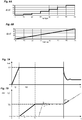
- the frequency operating points ⁇ st_i are advantageously distinct, but it is not necessary for them to follow a particular profile. It must therefore be understood that any frequency variation profile that makes it possible to define several different frequency operating points could be envisaged. As an example, two configurations are presented below on the Figures 6A and 6B .
- a first configuration represented on the Figure 6A comprises several successive stages, each bearing forming a frequency operating point ⁇ st_i distinct.
- the profile can be growing as on the Figure 6A , or decreasing.
- a second configuration represented on the Figure 6B has a linear ramp.
- the successive operating frequency points therefore belong to this ramp.
- the ramp can be growing as on the Figure 6B , or decreasing.
- the amplitude Vi of the voltage will remain identical for each operating point in frequency i.
- the diagram therefore consists simply of injecting the frequency profile into the LC control law.
- the identification module M1 then comprises an application module M11 of a current reference Iref in the control law LC, this module M11 being executed in parallel with the module M10.
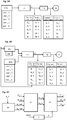
- the voltage module Vi is determined by a proportional-integral proportional regulator receiving as input the difference between the reference current Iref and the current Ip_m measured at the primary of the transformer.
- regulation can follow the pattern as shown in figure 3C .
- the currents measured on the three output phases (lp_m), connected to the primary of the transformer are transformed, thanks to a transformation of Park into two currents Id and Iq in the reference d, q.
- a proportional-integral controller receives as input the two measured currents Id, Iq as well as an reference Idref and a reference Iqref. At the output, the two reference voltages Vdref and Vqref are obtained.
- a module applying a Park transform makes it possible to convert these two reference voltages into three amplitude voltages Vi to be applied to the three output phases. This module also receives as input a phase shift angle derived from the applied stator frequency according to a defined profile, such as for example one of those described below. In this regulation, it is possible to choose the reference Idref equal to the current module and the reference Iqref to a zero value.
- the identification sequence then consists in acquiring, for each operating point ⁇ st_i in frequency, the current Ip_i and / or the voltage Vp_i at the primary of the transformer and respectively the current Is_i and / or the voltage Vs_i at the secondary of the transformer.
- the current Ip_i when the current Ip_i is acquired at the primary, the current is_i secondary must be acquired.
- the voltage Vp_i when the voltage Vp_i is acquired at the primary, the voltage Vs_i at the secondary must be acquired.
- the system can also be based on both the primary and secondary currents and the primary and secondary voltages to define the transfer function of the transformer TR, but only one of the quantities (current or voltage) must be understood. enough. In the remainder of the description, reference will be made to current and / or voltage acquisition and it should be understood that the acquisition of the current and / or the voltage at the primary of the transformer necessarily implies respectively the acquisition of the current and / or or secondary voltage.
- the control system comprises first means for acquiring the current and / or voltage at the primary of the transformer and second means for acquiring the current and / or voltage at the secondary of the transformer.
- the first acquisition means may comprise current and / or voltage measuring sensors SP placed at the primary of the transformer TR.
- the second acquisition means may comprise current and / or voltage measuring sensors Ss placed at the secondary of the transformer TR.
- the first acquisition means may comprise a first acquisition module M20 executed by the processing and control unit UC to acquire the current data Ip_i and / or the voltage data Vp_i measured at the primary of the transformer for each point of frequency operation ⁇ st_i.
- the second acquisition means may comprise a second acquisition module M21 executed by the processing and control unit UC for respectively acquiring the current data Is_i and / or the voltage data Vs_i measured at the secondary of the transformer TR for each operating point in frequency ⁇ st_i.
- the first acquisition module M20 and the second acquisition module M21 are connected to each measurement sensor in order to retrieve the current measurement data and / or the voltage measurement data.
- the first acquisition module and the second acquisition module are synchronized so as to make the data coincide at each acquisition instant. of currents acquired at the primary with the current data acquired at the secondary of the transformer for each operating point in frequency.
- the first acquisition module and the second acquisition module are synchronized so as to coincide in time the voltage data acquired at the primary with the voltage data acquired at the secondary of the transformer for each operating point in frequency.
- the first acquisition means may be those already used by the variable speed drive SD to implement its control law LC of the electric motor.
- the second acquisition means may comprise an external electronic card connected to the processing and control unit UC.
- the current and / or voltage sensors placed on the secondary of the transformer as well as the external electronic card can be used only for the implementation of the identification sequence and subsequently removed when starting the electric motor and during operation. normal installation.
- the identification module M1 initiates a step of acquiring current and / or voltage data by executing the first acquisition module M20 and the second acquisition module M21 defined herein. -above.
- the processing and control unit UC thus has a data table mapping each reference stator frequency value and a current value Ip_i and / or voltage Vp_i at the primary and a current value Is_i and / or voltage Vs_i at the secondary.
- the processing and control unit UC executes an analysis module M3 of the current and / or voltage data acquired at the primary and at the secondary level for each frequency operating point ⁇ st_i in order to determine for each operating point in frequency a gain ki and / or a phase shift ⁇ i, representative of a current transfer and / or voltage produced by the transformer.
- These data represent more precisely the inverse of the transfer function (gain and / or phase shift) of the transformer.
- This data is recorded by the processing and control unit UC in its storage means. The principle is illustrated by the figure 4 attached.
- the analysis module M3 is then configured to generate a transfer module M4 intended to be executed by the processing and control unit UC and configured to ensure the transfer of a current and / or a voltage to be applied to the primary current of the transformer in a current and / or a voltage present at the secondary, taking into account the stator frequency and the values of gain and / or phase shift stored at the end of the identification sequence.
- This transfer module M4 is used to generate the reference current path which is adapted to start the electric motor, while protecting the electric motor and the transformer.
- the startup sequence consists in determining and applying a reference current Iref (module M6).
- This reference current Iref is chosen at a value greater than a first threshold value, corresponding to the minimum current to be applied to rotate the synchronous electric motor, that is to say corresponding to the minimum of the charging current.
- the Figure 7A represents the trajectory of the reference current Iref applied at the input.
- a ramp of current up to a value V1 which is chosen to be greater than said first threshold value (S1) can be seen.
- the reference current Iref is then maintained at the value V1 (S2).
- the value V1 reached is chosen constant and the current is maintained at this value during the entire start-up sequence.
- the control unit UC applies a stator frequency trajectory ⁇ st_ref (module M7).
- the stator frequency ⁇ st_ref is chosen at the lowest possible value but higher than a second threshold value, synonymous with saturation of the transformer, as explained by the demonstration above.
- the Figure 7B represents the trajectory of the stator frequency ⁇ st_ref applied as input.
- the gray curve represents the frequency of the rotor and therefore the actual speed of the electric motor.
- the stator frequency ⁇ st_ref is firstly chosen to be zero during the rise ramp of the current and then follows a rise ramp once the reference current Iref has reached its constant value. Then the stator frequency ⁇ st_ref is preferably stabilized at its constant value V2 chosen. It is stabilized at this value V2 until the end of the start sequence.
- the control unit then maintains the control in current and frequency for a defined time (time at least greater than the inverse of the stator frequency) in order to guarantee the rotation of the motor (so that the motor speed is equal to the speed reference).
- the control unit knows the frequency of the motor, which is equal to the frequency of the voltage delivered by the variable speed drive, as well as an estimate of the rotor angle ⁇ .
- the control unit then switches the control of the synchronous electric motor to the main control law LC.
- This conventional start sequence is implemented taking into account a fixed gain for the transformer.
- the transfer module determined by the control method described above makes it possible to correct this startup sequence in order to adapt it to the installation and in particular to the actual gain and / or phase shift characteristics generated by the presence of the transformer.
- the transfer module M4 determined above thus makes it possible to correct the sequence.
- the frequency trajectory remains identical to that of the conventional sequence.
- the current follows a path that includes a first ramp up to a value V3 corresponding to the maximum value of the primary current to protect the drive and the transformer. This value is greater than the value V1 previously defined.
- the current therefore remains equal to the value V3 as long as the transfer module M4 generates a current reference higher than the value V3.
- the current then follows a downward curve to reach the value V1. It then has a bearing at the value V1.
- the gray curve represents the frequency of the rotor and therefore the actual speed of the electric motor.
Landscapes
- Engineering & Computer Science (AREA)
- Power Engineering (AREA)
- Control Of Ac Motors In General (AREA)
Applications Claiming Priority (1)
| Application Number | Priority Date | Filing Date | Title |
|---|---|---|---|
| FR1762421A FR3075512B1 (fr) | 2017-12-19 | 2017-12-19 | Procede de commande d'un moteur electrique incluant une sequence d'identification d'un transformateur |
Publications (2)
| Publication Number | Publication Date |
|---|---|
| EP3503380A1 true EP3503380A1 (de) | 2019-06-26 |
| EP3503380B1 EP3503380B1 (de) | 2022-02-16 |
Family
ID=62017388
Family Applications (1)
| Application Number | Title | Priority Date | Filing Date |
|---|---|---|---|
| EP18206896.5A Active EP3503380B1 (de) | 2017-12-19 | 2018-11-19 | Steuerverfahren eines elektromotors, das eine identifizierungssequenz eines transformators umfasst |
Country Status (5)
| Country | Link |
|---|---|
| US (1) | US10892693B2 (de) |
| EP (1) | EP3503380B1 (de) |
| CN (1) | CN109951109B (de) |
| ES (1) | ES2908263T3 (de) |
| FR (1) | FR3075512B1 (de) |
Families Citing this family (2)
| Publication number | Priority date | Publication date | Assignee | Title |
|---|---|---|---|---|
| JP7318727B2 (ja) * | 2019-11-05 | 2023-08-01 | 株式会社安川電機 | 電力変換装置、電力変換方法及びシステム |
| JP7423498B2 (ja) * | 2020-12-03 | 2024-01-29 | 株式会社ミツバ | モータ制御装置、モータ駆動システム、油圧発生装置、モータ制御方法、及びモータ制御プログラム |
Citations (2)
| Publication number | Priority date | Publication date | Assignee | Title |
|---|---|---|---|---|
| US20150002059A1 (en) * | 2013-06-29 | 2015-01-01 | Rockwell Automation Technologies, Inc. | Method and apparatus for stability control of open loop motor drive operation |
| EP2963802A1 (de) * | 2014-06-30 | 2016-01-06 | Schneider Toshiba Inverter Europe SAS | Steuerungsverfahren zum anlassen eines elektrischen synchronmotors |
Family Cites Families (7)
| Publication number | Priority date | Publication date | Assignee | Title |
|---|---|---|---|---|
| US5909098A (en) * | 1996-05-02 | 1999-06-01 | Reda Pump | Downhole pumping system with variable speed pulse-width modulated inverter coupled to electrical motor via non-gap transformer |
| US7932693B2 (en) * | 2005-07-07 | 2011-04-26 | Eaton Corporation | System and method of controlling power to a non-motor load |
| US7468595B2 (en) * | 2005-07-26 | 2008-12-23 | Eaton Corporation | System and method of controlling the start-up of an adjustable speed motor drive based sinusoidal output power conditioner |
| US7724549B2 (en) * | 2006-09-22 | 2010-05-25 | Rockwell Automation Technologies, Inc. | Integrated power conditioning system and housing for delivering operational power to a motor |
| AT506138B1 (de) * | 2007-11-22 | 2009-11-15 | Fronius Int Gmbh | Verfahren zur erkennung der betätigung eines bedienelements einer bedienfront und bedienfront mit zumindest einem bedienelement |
| CN103729008B (zh) * | 2012-10-12 | 2017-05-03 | 沈阳君印科技有限公司 | 宽电流范围交流恒流源补偿型控制方法 |
| US9054621B2 (en) * | 2013-04-23 | 2015-06-09 | Rockwell Automation Technologies, Inc. | Position sensorless open loop control for motor drives with output filter and transformer |
-
2017
- 2017-12-19 FR FR1762421A patent/FR3075512B1/fr not_active Expired - Fee Related
-
2018
- 2018-11-14 US US16/190,336 patent/US10892693B2/en active Active
- 2018-11-19 ES ES18206896T patent/ES2908263T3/es active Active
- 2018-11-19 EP EP18206896.5A patent/EP3503380B1/de active Active
- 2018-12-04 CN CN201811474171.2A patent/CN109951109B/zh active Active
Patent Citations (2)
| Publication number | Priority date | Publication date | Assignee | Title |
|---|---|---|---|---|
| US20150002059A1 (en) * | 2013-06-29 | 2015-01-01 | Rockwell Automation Technologies, Inc. | Method and apparatus for stability control of open loop motor drive operation |
| EP2963802A1 (de) * | 2014-06-30 | 2016-01-06 | Schneider Toshiba Inverter Europe SAS | Steuerungsverfahren zum anlassen eines elektrischen synchronmotors |
Also Published As
| Publication number | Publication date |
|---|---|
| FR3075512A1 (fr) | 2019-06-21 |
| CN109951109B (zh) | 2025-01-24 |
| CN109951109A (zh) | 2019-06-28 |
| EP3503380B1 (de) | 2022-02-16 |
| US10892693B2 (en) | 2021-01-12 |
| ES2908263T3 (es) | 2022-04-28 |
| FR3075512B1 (fr) | 2019-11-08 |
| US20190190414A1 (en) | 2019-06-20 |
Similar Documents
| Publication | Publication Date | Title |
|---|---|---|
| EP2684289B1 (de) | In einem stromwandler implementiertes steuerverfahren zur identifizierung von parametern in bezug auf die magnetische sättigung eines elektromotors | |
| EP2003461B1 (de) | Verfahren zum Feststellen eines Ausfalls einer oder mehrerer Phasen bei einem Dauermagnet-Synchronmotor | |
| EP1881594B1 (de) | Verfahren zur Justierung der Parameter eines Synchronmotors und Verwendung eines solchen Verfahrens in einer Drehzahlregelung | |
| FR2944659A1 (fr) | Procede de determination de la position du vecteur de flux d'un moteur | |
| EP3451525B1 (de) | Verfahren zur identifizierung der magnetischen sättigungsparameter eines asynchronen elektromotors | |
| EP3607649B1 (de) | Temperaturgesteuerte elektrische hochleistungsmaschine | |
| EP3287795A1 (de) | Bestimmung der frequenz eines wechselsignals | |
| FR2988234A1 (fr) | Procede de charge sans contact d'une batterie d'un vehicule automobile electrique | |
| EP3503380B1 (de) | Steuerverfahren eines elektromotors, das eine identifizierungssequenz eines transformators umfasst | |
| EP3069441B1 (de) | Verfahren und system zur steuerung eines mit geschnittenen spannungen versorgten kraftfahrzeug-drehstrom-elektromotors | |
| EP3229366A1 (de) | Steuerungsverfahren eines asynchronen elektromotors | |
| EP3401694B1 (de) | Identifizierungsverfahren des elektrischen widerstands eines rotors eines elektromotors | |
| EP2963802B1 (de) | Steuerungsverfahren zum anlassen eines elektrischen synchronmotors | |
| EP3166220B1 (de) | Vorrichtung zur dynamischen begrenzung, und verfahren zur dynamischen begrenzung durch eine solche vorrichtung | |
| EP3462603B1 (de) | Steuerungsverfahren zur überprüfung der kompatibilität zwischen einem drehzahlregler und dem eingangsfilter | |
| EP2780771B1 (de) | Verfahren und system zur korrektur der auf eine elektrische last anzuwendenden spannungen | |
| EP3711155B1 (de) | Verfahren zur steuerung einer elektrischen synchronmaschine | |
| FR3093813A1 (fr) | Détection du type d’un moteur électrique pour configuration d’un variateur de vitesse | |
| FR3102899A1 (fr) | Procédé de commande électrique d’un onduleur à trois niveaux | |
| EP3128667B1 (de) | Steuerungsverfahren zum anlassen eines elektrischen synchronmotors | |
| WO2013104582A2 (fr) | Procédé de commande mis en œuvre pour commander deux moteurs électriques synchrones à aimant permanent connectés en parallèle | |
| FR3024616A1 (fr) | Procede et dispositif de commande du couple electromagnetique d'un groupe motopropulseur | |
| WO2015121049A2 (fr) | Procede de commande d'une machine electrique a aimant permanent optimisant les pertes joule | |
| FR3029366A1 (fr) | Dispositif et procede de pilotage du couple d'une machine electrique a reluctance variable |
Legal Events
| Date | Code | Title | Description |
|---|---|---|---|
| PUAI | Public reference made under article 153(3) epc to a published international application that has entered the european phase |
Free format text: ORIGINAL CODE: 0009012 |
|
| STAA | Information on the status of an ep patent application or granted ep patent |
Free format text: STATUS: THE APPLICATION HAS BEEN PUBLISHED |
|
| AK | Designated contracting states |
Kind code of ref document: A1 Designated state(s): AL AT BE BG CH CY CZ DE DK EE ES FI FR GB GR HR HU IE IS IT LI LT LU LV MC MK MT NL NO PL PT RO RS SE SI SK SM TR |
|
| AX | Request for extension of the european patent |
Extension state: BA ME |
|
| STAA | Information on the status of an ep patent application or granted ep patent |
Free format text: STATUS: REQUEST FOR EXAMINATION WAS MADE |
|
| 17P | Request for examination filed |
Effective date: 20191128 |
|
| RBV | Designated contracting states (corrected) |
Designated state(s): AL AT BE BG CH CY CZ DE DK EE ES FI FR GB GR HR HU IE IS IT LI LT LU LV MC MK MT NL NO PL PT RO RS SE SI SK SM TR |
|
| STAA | Information on the status of an ep patent application or granted ep patent |
Free format text: STATUS: EXAMINATION IS IN PROGRESS |
|
| 17Q | First examination report despatched |
Effective date: 20200507 |
|
| GRAP | Despatch of communication of intention to grant a patent |
Free format text: ORIGINAL CODE: EPIDOSNIGR1 |
|
| STAA | Information on the status of an ep patent application or granted ep patent |
Free format text: STATUS: GRANT OF PATENT IS INTENDED |
|
| INTG | Intention to grant announced |
Effective date: 20211125 |
|
| GRAS | Grant fee paid |
Free format text: ORIGINAL CODE: EPIDOSNIGR3 |
|
| GRAA | (expected) grant |
Free format text: ORIGINAL CODE: 0009210 |
|
| STAA | Information on the status of an ep patent application or granted ep patent |
Free format text: STATUS: THE PATENT HAS BEEN GRANTED |
|
| AK | Designated contracting states |
Kind code of ref document: B1 Designated state(s): AL AT BE BG CH CY CZ DE DK EE ES FI FR GB GR HR HU IE IS IT LI LT LU LV MC MK MT NL NO PL PT RO RS SE SI SK SM TR |
|
| REG | Reference to a national code |
Ref country code: GB Ref legal event code: FG4D Free format text: NOT ENGLISH |
|
| REG | Reference to a national code |
Ref country code: CH Ref legal event code: EP |
|
| REG | Reference to a national code |
Ref country code: DE Ref legal event code: R096 Ref document number: 602018030863 Country of ref document: DE |
|
| REG | Reference to a national code |
Ref country code: AT Ref legal event code: REF Ref document number: 1469514 Country of ref document: AT Kind code of ref document: T Effective date: 20220315 |
|
| REG | Reference to a national code |
Ref country code: IE Ref legal event code: FG4D Free format text: LANGUAGE OF EP DOCUMENT: FRENCH |
|
| REG | Reference to a national code |
Ref country code: ES Ref legal event code: FG2A Ref document number: 2908263 Country of ref document: ES Kind code of ref document: T3 Effective date: 20220428 |
|
| REG | Reference to a national code |
Ref country code: LT Ref legal event code: MG9D |
|
| REG | Reference to a national code |
Ref country code: NL Ref legal event code: MP Effective date: 20220216 |
|
| REG | Reference to a national code |
Ref country code: AT Ref legal event code: MK05 Ref document number: 1469514 Country of ref document: AT Kind code of ref document: T Effective date: 20220216 |
|
| PG25 | Lapsed in a contracting state [announced via postgrant information from national office to epo] |
Ref country code: SE Free format text: LAPSE BECAUSE OF FAILURE TO SUBMIT A TRANSLATION OF THE DESCRIPTION OR TO PAY THE FEE WITHIN THE PRESCRIBED TIME-LIMIT Effective date: 20220216 Ref country code: RS Free format text: LAPSE BECAUSE OF FAILURE TO SUBMIT A TRANSLATION OF THE DESCRIPTION OR TO PAY THE FEE WITHIN THE PRESCRIBED TIME-LIMIT Effective date: 20220216 Ref country code: PT Free format text: LAPSE BECAUSE OF FAILURE TO SUBMIT A TRANSLATION OF THE DESCRIPTION OR TO PAY THE FEE WITHIN THE PRESCRIBED TIME-LIMIT Effective date: 20220616 Ref country code: NO Free format text: LAPSE BECAUSE OF FAILURE TO SUBMIT A TRANSLATION OF THE DESCRIPTION OR TO PAY THE FEE WITHIN THE PRESCRIBED TIME-LIMIT Effective date: 20220516 Ref country code: NL Free format text: LAPSE BECAUSE OF FAILURE TO SUBMIT A TRANSLATION OF THE DESCRIPTION OR TO PAY THE FEE WITHIN THE PRESCRIBED TIME-LIMIT Effective date: 20220216 Ref country code: LT Free format text: LAPSE BECAUSE OF FAILURE TO SUBMIT A TRANSLATION OF THE DESCRIPTION OR TO PAY THE FEE WITHIN THE PRESCRIBED TIME-LIMIT Effective date: 20220216 Ref country code: HR Free format text: LAPSE BECAUSE OF FAILURE TO SUBMIT A TRANSLATION OF THE DESCRIPTION OR TO PAY THE FEE WITHIN THE PRESCRIBED TIME-LIMIT Effective date: 20220216 Ref country code: BG Free format text: LAPSE BECAUSE OF FAILURE TO SUBMIT A TRANSLATION OF THE DESCRIPTION OR TO PAY THE FEE WITHIN THE PRESCRIBED TIME-LIMIT Effective date: 20220516 |
|
| PG25 | Lapsed in a contracting state [announced via postgrant information from national office to epo] |
Ref country code: PL Free format text: LAPSE BECAUSE OF FAILURE TO SUBMIT A TRANSLATION OF THE DESCRIPTION OR TO PAY THE FEE WITHIN THE PRESCRIBED TIME-LIMIT Effective date: 20220216 Ref country code: LV Free format text: LAPSE BECAUSE OF FAILURE TO SUBMIT A TRANSLATION OF THE DESCRIPTION OR TO PAY THE FEE WITHIN THE PRESCRIBED TIME-LIMIT Effective date: 20220216 Ref country code: GR Free format text: LAPSE BECAUSE OF FAILURE TO SUBMIT A TRANSLATION OF THE DESCRIPTION OR TO PAY THE FEE WITHIN THE PRESCRIBED TIME-LIMIT Effective date: 20220517 Ref country code: FI Free format text: LAPSE BECAUSE OF FAILURE TO SUBMIT A TRANSLATION OF THE DESCRIPTION OR TO PAY THE FEE WITHIN THE PRESCRIBED TIME-LIMIT Effective date: 20220216 Ref country code: AT Free format text: LAPSE BECAUSE OF FAILURE TO SUBMIT A TRANSLATION OF THE DESCRIPTION OR TO PAY THE FEE WITHIN THE PRESCRIBED TIME-LIMIT Effective date: 20220216 |
|
| PG25 | Lapsed in a contracting state [announced via postgrant information from national office to epo] |
Ref country code: IS Free format text: LAPSE BECAUSE OF FAILURE TO SUBMIT A TRANSLATION OF THE DESCRIPTION OR TO PAY THE FEE WITHIN THE PRESCRIBED TIME-LIMIT Effective date: 20220617 |
|
| PG25 | Lapsed in a contracting state [announced via postgrant information from national office to epo] |
Ref country code: SM Free format text: LAPSE BECAUSE OF FAILURE TO SUBMIT A TRANSLATION OF THE DESCRIPTION OR TO PAY THE FEE WITHIN THE PRESCRIBED TIME-LIMIT Effective date: 20220216 Ref country code: SK Free format text: LAPSE BECAUSE OF FAILURE TO SUBMIT A TRANSLATION OF THE DESCRIPTION OR TO PAY THE FEE WITHIN THE PRESCRIBED TIME-LIMIT Effective date: 20220216 Ref country code: RO Free format text: LAPSE BECAUSE OF FAILURE TO SUBMIT A TRANSLATION OF THE DESCRIPTION OR TO PAY THE FEE WITHIN THE PRESCRIBED TIME-LIMIT Effective date: 20220216 Ref country code: EE Free format text: LAPSE BECAUSE OF FAILURE TO SUBMIT A TRANSLATION OF THE DESCRIPTION OR TO PAY THE FEE WITHIN THE PRESCRIBED TIME-LIMIT Effective date: 20220216 Ref country code: DK Free format text: LAPSE BECAUSE OF FAILURE TO SUBMIT A TRANSLATION OF THE DESCRIPTION OR TO PAY THE FEE WITHIN THE PRESCRIBED TIME-LIMIT Effective date: 20220216 Ref country code: CZ Free format text: LAPSE BECAUSE OF FAILURE TO SUBMIT A TRANSLATION OF THE DESCRIPTION OR TO PAY THE FEE WITHIN THE PRESCRIBED TIME-LIMIT Effective date: 20220216 |
|
| REG | Reference to a national code |
Ref country code: DE Ref legal event code: R097 Ref document number: 602018030863 Country of ref document: DE |
|
| PG25 | Lapsed in a contracting state [announced via postgrant information from national office to epo] |
Ref country code: AL Free format text: LAPSE BECAUSE OF FAILURE TO SUBMIT A TRANSLATION OF THE DESCRIPTION OR TO PAY THE FEE WITHIN THE PRESCRIBED TIME-LIMIT Effective date: 20220216 |
|
| PLBE | No opposition filed within time limit |
Free format text: ORIGINAL CODE: 0009261 |
|
| STAA | Information on the status of an ep patent application or granted ep patent |
Free format text: STATUS: NO OPPOSITION FILED WITHIN TIME LIMIT |
|
| 26N | No opposition filed |
Effective date: 20221117 |
|
| PG25 | Lapsed in a contracting state [announced via postgrant information from national office to epo] |
Ref country code: SI Free format text: LAPSE BECAUSE OF FAILURE TO SUBMIT A TRANSLATION OF THE DESCRIPTION OR TO PAY THE FEE WITHIN THE PRESCRIBED TIME-LIMIT Effective date: 20220216 |
|
| PG25 | Lapsed in a contracting state [announced via postgrant information from national office to epo] |
Ref country code: MC Free format text: LAPSE BECAUSE OF FAILURE TO SUBMIT A TRANSLATION OF THE DESCRIPTION OR TO PAY THE FEE WITHIN THE PRESCRIBED TIME-LIMIT Effective date: 20220216 |
|
| REG | Reference to a national code |
Ref country code: CH Ref legal event code: PL |
|
| REG | Reference to a national code |
Ref country code: BE Ref legal event code: MM Effective date: 20221130 |
|
| PG25 | Lapsed in a contracting state [announced via postgrant information from national office to epo] |
Ref country code: LI Free format text: LAPSE BECAUSE OF NON-PAYMENT OF DUE FEES Effective date: 20221130 Ref country code: CH Free format text: LAPSE BECAUSE OF NON-PAYMENT OF DUE FEES Effective date: 20221130 |
|
| PG25 | Lapsed in a contracting state [announced via postgrant information from national office to epo] |
Ref country code: LU Free format text: LAPSE BECAUSE OF NON-PAYMENT OF DUE FEES Effective date: 20221119 |
|
| PG25 | Lapsed in a contracting state [announced via postgrant information from national office to epo] |
Ref country code: IE Free format text: LAPSE BECAUSE OF NON-PAYMENT OF DUE FEES Effective date: 20221119 |
|
| PG25 | Lapsed in a contracting state [announced via postgrant information from national office to epo] |
Ref country code: BE Free format text: LAPSE BECAUSE OF NON-PAYMENT OF DUE FEES Effective date: 20221130 |
|
| PG25 | Lapsed in a contracting state [announced via postgrant information from national office to epo] |
Ref country code: HU Free format text: LAPSE BECAUSE OF FAILURE TO SUBMIT A TRANSLATION OF THE DESCRIPTION OR TO PAY THE FEE WITHIN THE PRESCRIBED TIME-LIMIT; INVALID AB INITIO Effective date: 20181119 |
|
| PG25 | Lapsed in a contracting state [announced via postgrant information from national office to epo] |
Ref country code: CY Free format text: LAPSE BECAUSE OF FAILURE TO SUBMIT A TRANSLATION OF THE DESCRIPTION OR TO PAY THE FEE WITHIN THE PRESCRIBED TIME-LIMIT Effective date: 20220216 |
|
| PG25 | Lapsed in a contracting state [announced via postgrant information from national office to epo] |
Ref country code: MK Free format text: LAPSE BECAUSE OF FAILURE TO SUBMIT A TRANSLATION OF THE DESCRIPTION OR TO PAY THE FEE WITHIN THE PRESCRIBED TIME-LIMIT Effective date: 20220216 |
|
| PG25 | Lapsed in a contracting state [announced via postgrant information from national office to epo] |
Ref country code: MT Free format text: LAPSE BECAUSE OF FAILURE TO SUBMIT A TRANSLATION OF THE DESCRIPTION OR TO PAY THE FEE WITHIN THE PRESCRIBED TIME-LIMIT Effective date: 20220216 |
|
| PGFP | Annual fee paid to national office [announced via postgrant information from national office to epo] |
Ref country code: IT Payment date: 20241125 Year of fee payment: 7 Ref country code: ES Payment date: 20241218 Year of fee payment: 7 |
|
| PG25 | Lapsed in a contracting state [announced via postgrant information from national office to epo] |
Ref country code: TR Free format text: LAPSE BECAUSE OF FAILURE TO SUBMIT A TRANSLATION OF THE DESCRIPTION OR TO PAY THE FEE WITHIN THE PRESCRIBED TIME-LIMIT Effective date: 20220216 |
|
| PGFP | Annual fee paid to national office [announced via postgrant information from national office to epo] |
Ref country code: DE Payment date: 20251126 Year of fee payment: 8 |
|
| PGFP | Annual fee paid to national office [announced via postgrant information from national office to epo] |
Ref country code: GB Payment date: 20251125 Year of fee payment: 8 |
|
| PGFP | Annual fee paid to national office [announced via postgrant information from national office to epo] |
Ref country code: FR Payment date: 20251124 Year of fee payment: 8 |