EP3504443B1 - Ventilateur axial avec vrillage d'aube optimisé près du moyeu de la roue à aubes - Google Patents
Ventilateur axial avec vrillage d'aube optimisé près du moyeu de la roue à aubes Download PDFInfo
- Publication number
- EP3504443B1 EP3504443B1 EP17758042.0A EP17758042A EP3504443B1 EP 3504443 B1 EP3504443 B1 EP 3504443B1 EP 17758042 A EP17758042 A EP 17758042A EP 3504443 B1 EP3504443 B1 EP 3504443B1
- Authority
- EP
- European Patent Office
- Prior art keywords
- blade
- axial flow
- flow fan
- angle
- tip
- Prior art date
- Legal status (The legal status is an assumption and is not a legal conclusion. Google has not performed a legal analysis and makes no representation as to the accuracy of the status listed.)
- Active
Links
Images


Classifications
-
- F—MECHANICAL ENGINEERING; LIGHTING; HEATING; WEAPONS; BLASTING
- F04—POSITIVE - DISPLACEMENT MACHINES FOR LIQUIDS; PUMPS FOR LIQUIDS OR ELASTIC FLUIDS
- F04D—NON-POSITIVE-DISPLACEMENT PUMPS
- F04D29/00—Details, component parts, or accessories
- F04D29/26—Rotors specially for elastic fluids
- F04D29/32—Rotors specially for elastic fluids for axial flow pumps
- F04D29/38—Blades
- F04D29/384—Blades characterised by form
Definitions
- the invention relates to an axial flow fan with an improved wing design.
- Axial flow fans are well known in the art and many different designs have been proposed and manufactured in order to improve the performance of the fan, in particular with respect to generation of noise and improved power efficiency. It is an object of the present invention to provide an improved fan design to improve the efficiency of the fan.
- an axial flow fan according to claim 1. It comprises a hub rotatable about an axis; an annular shroud extending concentric with said axis in a radial distance from said hub; a plurality of fan blades connected at a root end to said hub and having a free tip end extending radially towards said shroud, and a fan driver coupled to said hub and arranged for driving the rotation of said hub around the axis.
- WO 2015/090318 also discloses an example of an axial flow fan with a number of the wings designed for reducing the power consumption by gradually angling the wings.
- the chord angle in WO 2015/090318 is significantly steeper than the chord angle obtained with the above axial flow fan, which has shown to introduce an improved efficiency of 15% in terms of improved energy efficiency.
- the angle ⁇ root deviates less than 1 ° from the curve defined by the equation within the root area.
- substantially meant a deviation of up to 5°.
- the angle ⁇ middle deviates less than 4° from the curve defined by the equation within the middle area.
- the angle ⁇ middle deviates less than 3° from the curve defined by the equation within the middle area.
- the angle ⁇ middle deviates less than 2° from the curve defined by the equation within the middle area.
- the angle ⁇ middle deviates less than 1° from the curve defined by the equation within the middle area.
- substantially meant a deviation of up to 5°.
- the angle ⁇ tip deviates less than 4° from the curve defined by the equation within the tip area.
- the angle ⁇ tip deviates less than 3° from the curve defined by the equation within the tip area.
- the angle ⁇ tip deviates less than 2° from the curve defined by the equation within the tip area.
- the angle ⁇ tip deviates less than 1° from the curve defined by the equation within the tip area.
- R is in the range of 500 to 900 millimetres, such as 600 to 800 millimetres, or such as 650 to 750 millimetres.
- the inner radius of the annular shroud is in the range of 600 to 1500 millimetres, such as 700 to 1300 millimetres, or such as 800 to 900 millimetres. The inner radius of the annular shroud is normally smaller than R.
- the radius ( R hub ) of the hub is in the range of 50 to 150 millimetres, such as 60 to 120 millimetres, or such as 70 to 80 millimetres.
- the fan may further comprise a diffuser arranged concentric with said axis at a downstream position of the annular shroud.
- the diffuser has a conical shape with a diffusion angle in the range of 2 to 15° to the axisof rotation of the rotor, preferably in the range of 6 to 10°.
- the fan may also further comprise an inlet part provided with a bellmouth arranged concentric with said axis at an upstream position of the annular shroud.
- the hub comprises a seating part allowing the blades to be arranged in a plurality of blade pitch angles, and blade locking part for locking the blade pitch angle of the at least one blade into a specific blade pitch angle, wherein said locking part is designed to lock said blade into one specific blade pitch angle only.
- the blades each comprises a recess cooperating with a corresponding pin of the locking part.
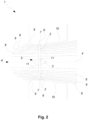
- FIG. 1 An axial flow fan 1 according to an embodiment of the invention is shown in figures 1 and 2 , where figure 1 shows a perspective view of an axial flow fan 1 and figure 2 shows a longitudinal schematic cross-section of an axial flow fan 1.
- the fan 1 comprises a hub 3 where to a plurality of fan blades 2 are connected at the root end 11 of the blades 2.
- the free tip end 7 of the blades 2 extend radially towards the shroud 6 as shown in figure 2 .
- the fan 1 in figure 1 has three blades 2, but may as well be equipped with any convenient number of blades 2. It is generally preferred that the rotor 5 of the fan comprises from 3 to 6 blades.
- the fan has a fan driver (not shown) coupled to the hub 3 and arranged for driving the rotation of the hub 3 around the axis 4 shown in figure 2 .
- the fan driver may be arranged in the hub 3 or next to the hub 3 and be connected thereto by means of a drive arrangement, e.g. a belt drive (not shown).
- the hub 3 and the blades 2 form a rotor 5, which is rotated about an axis 4 (see figure 2 ) by means of the fan driver, e.g. a motor.
- the rotor 5 is arranged inside the cylindrical shroud 6 which is concentric arranged about the axis 4 so there is a clearance between the tip 7 of the blades 2 and the shroud 6.
- the rotation of the rotor 5 drives a flow of air axially through the fan 1 in the direction of the arrow A as shown in figure 2 .
- the flow path through the fan 1 is illustrated by streamlines 8 indicated in figure 2 .
- the shroud 6 is preceded by an inlet part 9 arranged upstream of the shroud, i.e. in the direction against the driven flow A, where the inlet part 9 also is concentric with the axis 4 and comprises a bellmouth to smoothen the flow at the inlet part 9 in order to avoid separation of the flow.
- the passage of the air flow through the rotor 5 causes a pressure increase which is further increased by regained part of the kinetic energy present in of the air flow immediately after the rotor due to the axial velocity component by means of a diffuser 10 arranged downstream of the shroud 6 and concentric with the axis 4.
- the diffuser 10 has a conical shape with an diffusion angle of 8.5° to the centre line, i.e. to the axis 4 of rotation of the rotor 5.
- the blades 2 are attached by their root end 11 to the hub 3, preferably in a manner discussed later.
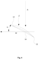
- a cross section of a fan blade 2 is shown in figure 4 with indication of the leading edge 12 of the blade 2 as well as the trailing edge 13 of the blade 2.
- the chord line 14 is extending between the leading edge 12 and the trailing edge 13, and the length of the chord of the blade 2 is defined by the distance between the leading edge 12 and the trailing edge 13.
- the blade 2 is moved in the direction indicated as M on figure 4 due to the rotation of the rotor 5 of the fan 1 during operation thereof.
- the angle ⁇ between the chord line 14 and the direction of movement M is indicated on figure 4 together with the direction A of the incoming air flow.
- the direction A is depicted as being perpendicular to the direction M of movement which is generally the case for an axial flow fan 1.
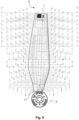
- Figure 5 shows a blade 2 according to the invention connected to by the root end 11 to a hub 3.
- a number of cross sectional cut from the first cross sectional cut A-A starts at the root end 11 to the last cross sectional cut 40-40 at the tip end 7 of the blade 2 are marked in figure 5 .
- the cross sectional cuts are evenly distributed over the length of the blade 2.
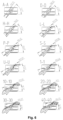
- Figure 6 shows selected examples of the cross sectional cuts of the blade 2 shown in figure 5 .
- the angle ⁇ between the chord line 14 and the direction of movement M are listed in the cross sectional cuts in figure 6 along with a value of the chord length.
- Table 1 lists the values for the chord length, the angle ⁇ between the chord line 14 and the direction of movement M, the radial distance r at the different cross sectional cuts of the blade 2 shown in figure 5 .
- Table 1 Cut r/R r ⁇ Chord ⁇ Eq. 1 Dev. Eq. 1 ⁇ Eq. 2 Dev. Eq. 2 Dev. Eq. 3 ⁇ Eq.
- the first column of the table is the cross-sectional cut as seen in figure 5
- the next four columns provide the parameters of the blade 2 as found by standard design tools
- the last six columns are the chord angles ⁇ found by means of Eq. 1, Eq. 2 and Eq. 3, and the respective deviations between the calculated angles using Eq. 1, Eq. 2 and Eq. 3 and the measured angle.
- the assembly in figure 1 also show a seating part 16 of the hub 3, three blades 2 and three locking parts 18 for an axial flow fan according to an aspect of the present invention.
- the blades 2 are at the root end 11 equipped with a projection 15 that allows the individual blade 2 to be seated in a blade seating opening 17 of the seating part 16 at any pitch angle of the blade 2 as desired, the projections 15 being rotatable in the U-shaped seating openings 17.
- the blade root protections 15 being equipped with a recess (not visible) designed for cooperating with a pin 20 having a rectangular cross-section, the pin 20 being extending from the body of a locking part 18 which is suited to the inserted into the blade seating opening 17 when the blade root projection 15 is in place so as to lock the pitch angle of the blade 2 to a specific blade pitch angle defined by the locking part 18.
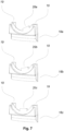
- FIG 7 is shown three different locking parts 18a, 18b, 18c where the pin 20a, 20b, 20c are arranged at different positions to define different pitch angles of the blade 2.
- the locking parts 18a, 18b, 18c are provided with side tracks 19 to accommodate the edges of the blade seating opening 17 of the seating part 16 of the hub 3.
Landscapes
- Engineering & Computer Science (AREA)
- Mechanical Engineering (AREA)
- General Engineering & Computer Science (AREA)
- Structures Of Non-Positive Displacement Pumps (AREA)
Claims (15)
- Ventilateur à flux axial (1) comprenant :- un moyeu (3) pouvant tourner autour d'un axe (4) ;- un carénage annulaire (6) s'étendant concentriquement audit axe (4) sur une distance radiale à partir dudit moyeu (3) ;- une pluralité de pales (2) de ventilateur reliées au niveau d'une extrémité de pied (11) audit moyeu (3) et ayant une extrémité de bout libre (7) s'étendant radialement vers ledit carénage (6), et- un dispositif d'entraînement de ventilateur accouplé audit moyeu et disposé pour entraîner la rotation dudit moyeu autour de l'axe, dans lequel pour R étant la distance radiale dudit axe (4) à l'extrémité de bout libre (7) de la pale et r étant la distance radiale à partir dudit axe (4), l'angle θ entre un plan de rotation des pales et la corde du profil de chaque pale à la position radiale de r/R = 0,34 est dans la plage de 20° à 40°,le ventilateur à flux axial étant caractérisé en ce que la pluralité de pales (2) de ventilateur comprennent chacune une zone de pied s'étendant d'une position radiale de r/R = 0,17 à une position radiale de r/R = 0,34, la zone de pied ayant un angle de pied Δθpied s'étendant entre la corde du profil de la pale en toute position radiale dans la zone de pied et la corde du profil à la position radiale de r/R = 0,34, Δθpied suivant une courbe définie comme :

- Ventilateur à flux axial selon la revendication 1, dans lequel la pluralité de pales de ventilateur comprennent chacune une zone centrale s'étendant de la position radiale de r/R = 0,34 à la position radiale de r/R=0,72, la zone centrale ayant un angle de centre Δθcentre s'étendant entre la corde du profil de la pale en toute position radiale dans la zone centrale et la corde du profil à la position radiale de r/R = 0,72, Δθcentre suivant une courbe définie comme :

- Ventilateur à flux axial selon la revendication 1 ou 2, dans lequel la pluralité de pales de ventilateur comprennent chacune une zone de bout s'étendant de la position radiale de r/R = 0,72 au bout de l'extrémité de bout libre à r/R = 1, la zone de bout ayant un angle de bout Δθbout s'étendant entre la corde du profil de la pale en toute position radiale dans la zone de bout et la corde du profil à la position radiale de r/R = 1, Δθbout suivant une courbe définie comme :

- Ventilateur à flux axial selon l'une quelconque des revendications précédentes, dans lequel l'angle θ entre un plan de rotation des pales et la corde du profil de la pale à la position radiale de r/R = 0,34 est dans la plage de 25 à 35°.
- Ventilateur à flux axial selon l'une quelconque des revendications précédentes, dans lequel :- l'angle Δθcentre dévie de moins de 4°, de préférence de moins de 3°, plus préférablement de moins de 2°, encore plus préférablement de moins de 1° de la courbe définie par l'équation à l'intérieur de la zone centrale ; et/ou- l'angle Δθbout dévie de moins de 4°, de préférence de moins de 3°, plus préférablement de moins de 2°, encore plus préférablement de moins de 1° de la courbe définie par l'équation à l'intérieur de la zone de bout.
- Ventilateur à flux axial selon l'une quelconque des revendications précédentes, dans lequel R est dans la plage de 500 à 900 millimètres.
- Ventilateur à flux axial selon l'une quelconque des revendications précédentes, dans lequel la corde du profil augmente dans la zone de pied à partir du moyeu vers la position radiale de r/R = 0,34, s'aplatit jusqu'à la position radiale de r/R = 0,40 et diminue vers le bout de la pale à la position radiale de r/R = 1.
- Ventilateur à flux axial selon l'une quelconque des revendications précédentes, dans lequel le rayon interne du carénage annulaire est dans la plage de 600 à 1 500 millimètres.
- Ventilateur à flux axial selon l'une quelconque des revendications précédentes, dans lequel le rayon (Rmoyeu ) du moyeu est dans la plage de 50 à 150 millimètres.
- Ventilateur à flux axial selon l'une quelconque des revendications précédentes, comprenant un diffuseur (10) disposé concentriquement audit axe (4) en une position en aval du carénage annulaire (6).
- Ventilateur à flux axial selon la revendication 10, dans lequel le diffuseur (10) a une forme conique avec un angle de diffusion dans la plage de 2 à 15°, de préférence dans la plage de 6 à 10°, par rapport à l'axe (4) de rotation du rotor.
- Ventilateur à flux axial selon l'une quelconque des revendications précédentes, comprenant une partie d'entrée (9) dotée d'un évasement disposé concentriquement audit axe (4) en une position en amont du carénage annulaire (6).
- Ventilateur à flux axial selon l'une quelconque des revendications précédentes, dans lequel le moyeu (3) comprend- une partie d'appui (16) permettant aux pales (2) d'être disposées en une pluralité d'angles de pas de pale, et- une partie de blocage (18) de pale destinée à bloquer l'angle de pas de pale de ladite au moins une pale (2) en un angle spécifique de pas de pale,dans lequel ladite partie de blocage (18, 18a, 18b, 18c) est conçue pour bloquer ladite pale (2) en un seul angle spécifique de pas de pale.
- Ventilateur à flux axial selon la revendication 13, comprenant une partie de blocage (18, 18a, 18b, 18c) pour chacune des pales (2).
- Ventilateur à flux axial selon la revendication 13 ou 14, dans lequel les pales (2) comprennent chacune un retrait coopérant avec une broche correspondante (20, 20a, 20b, 20c) de la partie de blocage (18, 18a, 18b, 18c).
Applications Claiming Priority (2)
| Application Number | Priority Date | Filing Date | Title |
|---|---|---|---|
| DKPA201670645A DK179200B1 (en) | 2016-08-25 | 2016-08-25 | Improved wing for an axial flow fan |
| PCT/DK2017/050272 WO2018036598A1 (fr) | 2016-08-25 | 2017-08-22 | Ventilateur à flux axial à torsion de pale optimisée à proximité du moyeu de roue |
Publications (3)
| Publication Number | Publication Date |
|---|---|
| EP3504443A1 EP3504443A1 (fr) | 2019-07-03 |
| EP3504443C0 EP3504443C0 (fr) | 2023-07-19 |
| EP3504443B1 true EP3504443B1 (fr) | 2023-07-19 |
Family
ID=61008654
Family Applications (1)
| Application Number | Title | Priority Date | Filing Date |
|---|---|---|---|
| EP17758042.0A Active EP3504443B1 (fr) | 2016-08-25 | 2017-08-22 | Ventilateur axial avec vrillage d'aube optimisé près du moyeu de la roue à aubes |
Country Status (4)
| Country | Link |
|---|---|
| EP (1) | EP3504443B1 (fr) |
| DK (1) | DK179200B1 (fr) |
| ES (1) | ES2951073T3 (fr) |
| WO (1) | WO2018036598A1 (fr) |
Citations (1)
| Publication number | Priority date | Publication date | Assignee | Title |
|---|---|---|---|---|
| WO2018229081A1 (fr) * | 2017-06-12 | 2018-12-20 | Valeo Systemes Thermiques | Ventilateur de vehicule automobile |
Family Cites Families (7)
| Publication number | Priority date | Publication date | Assignee | Title |
|---|---|---|---|---|
| US2027745A (en) * | 1933-09-13 | 1936-01-14 | Jeffrey Mfg Co | Ventilator |
| US4569632A (en) * | 1983-11-08 | 1986-02-11 | Airflow Research And Manufacturing Corp. | Back-skewed fan |
| US6065937A (en) * | 1998-02-03 | 2000-05-23 | Siemens Canada Limited | High efficiency, axial flow fan for use in an automotive cooling system |
| KR100332539B1 (ko) * | 1998-12-31 | 2002-04-13 | 신영주 | 축류팬 |
| US7249931B2 (en) * | 2002-03-30 | 2007-07-31 | University Of Central Florida Research Foundation, Inc. | High efficiency air conditioner condenser fan with performance enhancements |
| ATE444448T1 (de) * | 2006-05-31 | 2009-10-15 | Bosch Gmbh Robert | Axialgebläseanordnung |
| WO2015090318A1 (fr) * | 2013-12-17 | 2015-06-25 | Dacs A/S | Soufflante à écoulement axial à pales tournés selon un rapport de pas de pale qui diminue de façon (quasi)linéaire avec la position radiale |
-
2016
- 2016-08-25 DK DKPA201670645A patent/DK179200B1/en active
-
2017
- 2017-08-22 ES ES17758042T patent/ES2951073T3/es active Active
- 2017-08-22 WO PCT/DK2017/050272 patent/WO2018036598A1/fr not_active Ceased
- 2017-08-22 EP EP17758042.0A patent/EP3504443B1/fr active Active
Patent Citations (1)
| Publication number | Priority date | Publication date | Assignee | Title |
|---|---|---|---|---|
| WO2018229081A1 (fr) * | 2017-06-12 | 2018-12-20 | Valeo Systemes Thermiques | Ventilateur de vehicule automobile |
Also Published As
| Publication number | Publication date |
|---|---|
| DK201670645A1 (en) | 2018-01-29 |
| EP3504443C0 (fr) | 2023-07-19 |
| WO2018036598A1 (fr) | 2018-03-01 |
| DK179200B1 (en) | 2018-01-29 |
| EP3504443A1 (fr) | 2019-07-03 |
| ES2951073T3 (es) | 2023-10-17 |
Similar Documents
| Publication | Publication Date | Title |
|---|---|---|
| EP1276994B1 (fr) | Ventilateur, notamment pour la ventilation de systemes electroniques | |
| US9091174B2 (en) | Method of reducing asymmetric fluid flow effects in a passage | |
| EP2543818B1 (fr) | Aube de souflante subsonique en flèche | |
| EP3070266B1 (fr) | Agencement de turboréacteur avec variations de lame de canal | |
| EP2669474B1 (fr) | Canal de passage pour une turbomachine et turbomachine | |
| EP3842644A1 (fr) | Ventilateur contrarotatif | |
| EP2172648A1 (fr) | Pale pour rotor d'éolienne | |
| JPS5990797A (ja) | 遠心圧縮機及び圧縮方法 | |
| WO2018060068A1 (fr) | Aubes à tracé en forme de s dans la direction d'écoulement pour des roues à aubes à type de construction radiale | |
| EP1774179B1 (fr) | Aube de compresseur | |
| EP2739861B1 (fr) | Ventilateur axial | |
| DE19502808A1 (de) | Radialströmungsmaschine | |
| EP2824277B1 (fr) | Etage de turbine à gaz | |
| WO2011012352A1 (fr) | Géométrie d'entrée pour roues semi-axiales de ventilateur | |
| WO2005116404A1 (fr) | Aube comportant une zone de transition | |
| WO2016046036A1 (fr) | Rotor de compresseur radial et compresseur radial associé | |
| EP3504443B1 (fr) | Ventilateur axial avec vrillage d'aube optimisé près du moyeu de la roue à aubes | |
| EP2241722A1 (fr) | Conduit d'aube d'entrée et compresseur | |
| US20160319836A1 (en) | Axial flow fan with blades twisted according to a blade pitch ratio that decreases (quasi) linearly with the radial position | |
| WO2012123080A1 (fr) | Roue de ventilateur | |
| US10794392B2 (en) | Hub for propeller having variable-pitch blades, with radial and axial dimensioning variation | |
| EP3298285B1 (fr) | Aube directrice pour un diffuseur aubagé d'un compresseur centrifuge | |
| EP3760876A1 (fr) | Diffuseur pour une turbomachine | |
| EP3636880B1 (fr) | Roue de turbine | |
| EP3502482B1 (fr) | Aube de compresseur avec distribution dans le sens de l'envergure de l'angle de décalage modifié |
Legal Events
| Date | Code | Title | Description |
|---|---|---|---|
| STAA | Information on the status of an ep patent application or granted ep patent |
Free format text: STATUS: UNKNOWN |
|
| STAA | Information on the status of an ep patent application or granted ep patent |
Free format text: STATUS: THE INTERNATIONAL PUBLICATION HAS BEEN MADE |
|
| PUAI | Public reference made under article 153(3) epc to a published international application that has entered the european phase |
Free format text: ORIGINAL CODE: 0009012 |
|
| STAA | Information on the status of an ep patent application or granted ep patent |
Free format text: STATUS: REQUEST FOR EXAMINATION WAS MADE |
|
| 17P | Request for examination filed |
Effective date: 20190322 |
|
| AK | Designated contracting states |
Kind code of ref document: A1 Designated state(s): AL AT BE BG CH CY CZ DE DK EE ES FI FR GB GR HR HU IE IS IT LI LT LU LV MC MK MT NL NO PL PT RO RS SE SI SK SM TR |
|
| STAA | Information on the status of an ep patent application or granted ep patent |
Free format text: STATUS: EXAMINATION IS IN PROGRESS |
|
| 17Q | First examination report despatched |
Effective date: 20211001 |
|
| GRAP | Despatch of communication of intention to grant a patent |
Free format text: ORIGINAL CODE: EPIDOSNIGR1 |
|
| STAA | Information on the status of an ep patent application or granted ep patent |
Free format text: STATUS: GRANT OF PATENT IS INTENDED |
|
| INTG | Intention to grant announced |
Effective date: 20230303 |
|
| GRAS | Grant fee paid |
Free format text: ORIGINAL CODE: EPIDOSNIGR3 |
|
| GRAA | (expected) grant |
Free format text: ORIGINAL CODE: 0009210 |
|
| STAA | Information on the status of an ep patent application or granted ep patent |
Free format text: STATUS: THE PATENT HAS BEEN GRANTED |
|
| AK | Designated contracting states |
Kind code of ref document: B1 Designated state(s): AL AT BE BG CH CY CZ DE DK EE ES FI FR GB GR HR HU IE IS IT LI LT LU LV MC MK MT NL NO PL PT RO RS SE SI SK SM TR |
|
| REG | Reference to a national code |
Ref country code: GB Ref legal event code: FG4D |
|
| REG | Reference to a national code |
Ref country code: CH Ref legal event code: EP |
|
| REG | Reference to a national code |
Ref country code: DE Ref legal event code: R096 Ref document number: 602017071482 Country of ref document: DE |
|
| REG | Reference to a national code |
Ref country code: IE Ref legal event code: FG4D |
|
| U01 | Request for unitary effect filed |
Effective date: 20230719 |
|
| U07 | Unitary effect registered |
Designated state(s): AT BE BG DE DK EE FI FR IT LT LU LV MT NL PT SE SI Effective date: 20230725 |
|
| REG | Reference to a national code |
Ref country code: ES Ref legal event code: FG2A Ref document number: 2951073 Country of ref document: ES Kind code of ref document: T3 Effective date: 20231017 |
|
| U20 | Renewal fee for the european patent with unitary effect paid |
Year of fee payment: 7 Effective date: 20230914 |
|
| REG | Reference to a national code |
Ref country code: LT Ref legal event code: MG9D |
|
| PG25 | Lapsed in a contracting state [announced via postgrant information from national office to epo] |
Ref country code: GR Free format text: LAPSE BECAUSE OF FAILURE TO SUBMIT A TRANSLATION OF THE DESCRIPTION OR TO PAY THE FEE WITHIN THE PRESCRIBED TIME-LIMIT Effective date: 20231020 |
|
| PG25 | Lapsed in a contracting state [announced via postgrant information from national office to epo] |
Ref country code: IS Free format text: LAPSE BECAUSE OF FAILURE TO SUBMIT A TRANSLATION OF THE DESCRIPTION OR TO PAY THE FEE WITHIN THE PRESCRIBED TIME-LIMIT Effective date: 20231119 |
|
| PG25 | Lapsed in a contracting state [announced via postgrant information from national office to epo] |
Ref country code: RS Free format text: LAPSE BECAUSE OF FAILURE TO SUBMIT A TRANSLATION OF THE DESCRIPTION OR TO PAY THE FEE WITHIN THE PRESCRIBED TIME-LIMIT Effective date: 20230719 Ref country code: NO Free format text: LAPSE BECAUSE OF FAILURE TO SUBMIT A TRANSLATION OF THE DESCRIPTION OR TO PAY THE FEE WITHIN THE PRESCRIBED TIME-LIMIT Effective date: 20231019 Ref country code: IS Free format text: LAPSE BECAUSE OF FAILURE TO SUBMIT A TRANSLATION OF THE DESCRIPTION OR TO PAY THE FEE WITHIN THE PRESCRIBED TIME-LIMIT Effective date: 20231119 Ref country code: HR Free format text: LAPSE BECAUSE OF FAILURE TO SUBMIT A TRANSLATION OF THE DESCRIPTION OR TO PAY THE FEE WITHIN THE PRESCRIBED TIME-LIMIT Effective date: 20230719 Ref country code: GR Free format text: LAPSE BECAUSE OF FAILURE TO SUBMIT A TRANSLATION OF THE DESCRIPTION OR TO PAY THE FEE WITHIN THE PRESCRIBED TIME-LIMIT Effective date: 20231020 |
|
| PG25 | Lapsed in a contracting state [announced via postgrant information from national office to epo] |
Ref country code: PL Free format text: LAPSE BECAUSE OF FAILURE TO SUBMIT A TRANSLATION OF THE DESCRIPTION OR TO PAY THE FEE WITHIN THE PRESCRIBED TIME-LIMIT Effective date: 20230719 |
|
| REG | Reference to a national code |
Ref country code: CH Ref legal event code: PL |
|
| REG | Reference to a national code |
Ref country code: DE Ref legal event code: R097 Ref document number: 602017071482 Country of ref document: DE |
|
| PG25 | Lapsed in a contracting state [announced via postgrant information from national office to epo] |
Ref country code: SM Free format text: LAPSE BECAUSE OF FAILURE TO SUBMIT A TRANSLATION OF THE DESCRIPTION OR TO PAY THE FEE WITHIN THE PRESCRIBED TIME-LIMIT Effective date: 20230719 Ref country code: RO Free format text: LAPSE BECAUSE OF FAILURE TO SUBMIT A TRANSLATION OF THE DESCRIPTION OR TO PAY THE FEE WITHIN THE PRESCRIBED TIME-LIMIT Effective date: 20230719 Ref country code: CZ Free format text: LAPSE BECAUSE OF FAILURE TO SUBMIT A TRANSLATION OF THE DESCRIPTION OR TO PAY THE FEE WITHIN THE PRESCRIBED TIME-LIMIT Effective date: 20230719 Ref country code: CH Free format text: LAPSE BECAUSE OF NON-PAYMENT OF DUE FEES Effective date: 20230831 Ref country code: SK Free format text: LAPSE BECAUSE OF FAILURE TO SUBMIT A TRANSLATION OF THE DESCRIPTION OR TO PAY THE FEE WITHIN THE PRESCRIBED TIME-LIMIT Effective date: 20230719 Ref country code: MC Free format text: LAPSE BECAUSE OF FAILURE TO SUBMIT A TRANSLATION OF THE DESCRIPTION OR TO PAY THE FEE WITHIN THE PRESCRIBED TIME-LIMIT Effective date: 20230719 |
|
| REG | Reference to a national code |
Ref country code: IE Ref legal event code: MM4A |
|
| PLBE | No opposition filed within time limit |
Free format text: ORIGINAL CODE: 0009261 |
|
| STAA | Information on the status of an ep patent application or granted ep patent |
Free format text: STATUS: NO OPPOSITION FILED WITHIN TIME LIMIT |
|
| 26N | No opposition filed |
Effective date: 20240422 |
|
| GBPC | Gb: european patent ceased through non-payment of renewal fee |
Effective date: 20231019 |
|
| PG25 | Lapsed in a contracting state [announced via postgrant information from national office to epo] |
Ref country code: IE Free format text: LAPSE BECAUSE OF NON-PAYMENT OF DUE FEES Effective date: 20230822 |
|
| PG25 | Lapsed in a contracting state [announced via postgrant information from national office to epo] |
Ref country code: GB Free format text: LAPSE BECAUSE OF NON-PAYMENT OF DUE FEES Effective date: 20231019 |
|
| PG25 | Lapsed in a contracting state [announced via postgrant information from national office to epo] |
Ref country code: IE Free format text: LAPSE BECAUSE OF NON-PAYMENT OF DUE FEES Effective date: 20230822 Ref country code: GB Free format text: LAPSE BECAUSE OF NON-PAYMENT OF DUE FEES Effective date: 20231019 |
|
| U20 | Renewal fee for the european patent with unitary effect paid |
Year of fee payment: 8 Effective date: 20240827 |
|
| PG25 | Lapsed in a contracting state [announced via postgrant information from national office to epo] |
Ref country code: CY Free format text: LAPSE BECAUSE OF FAILURE TO SUBMIT A TRANSLATION OF THE DESCRIPTION OR TO PAY THE FEE WITHIN THE PRESCRIBED TIME-LIMIT; INVALID AB INITIO Effective date: 20170822 |
|
| PG25 | Lapsed in a contracting state [announced via postgrant information from national office to epo] |
Ref country code: HU Free format text: LAPSE BECAUSE OF FAILURE TO SUBMIT A TRANSLATION OF THE DESCRIPTION OR TO PAY THE FEE WITHIN THE PRESCRIBED TIME-LIMIT; INVALID AB INITIO Effective date: 20170822 |
|
| U20 | Renewal fee for the european patent with unitary effect paid |
Year of fee payment: 9 Effective date: 20250827 |
|
| PGFP | Annual fee paid to national office [announced via postgrant information from national office to epo] |
Ref country code: ES Payment date: 20250926 Year of fee payment: 9 |
|
| PG25 | Lapsed in a contracting state [announced via postgrant information from national office to epo] |
Ref country code: TR Free format text: LAPSE BECAUSE OF FAILURE TO SUBMIT A TRANSLATION OF THE DESCRIPTION OR TO PAY THE FEE WITHIN THE PRESCRIBED TIME-LIMIT Effective date: 20230719 |