EP3505230A1 - Dispositif de mélange à pompe de transport intégrée - Google Patents
Dispositif de mélange à pompe de transport intégrée Download PDFInfo
- Publication number
- EP3505230A1 EP3505230A1 EP19150614.6A EP19150614A EP3505230A1 EP 3505230 A1 EP3505230 A1 EP 3505230A1 EP 19150614 A EP19150614 A EP 19150614A EP 3505230 A1 EP3505230 A1 EP 3505230A1
- Authority
- EP
- European Patent Office
- Prior art keywords
- mixing
- mixing device
- feed
- inlet
- module
- Prior art date
- Legal status (The legal status is an assumption and is not a legal conclusion. Google has not performed a legal analysis and makes no representation as to the accuracy of the status listed.)
- Granted
Links
Images




Classifications
-
- B—PERFORMING OPERATIONS; TRANSPORTING
- B01—PHYSICAL OR CHEMICAL PROCESSES OR APPARATUS IN GENERAL
- B01F—MIXING, e.g. DISSOLVING, EMULSIFYING OR DISPERSING
- B01F23/00—Mixing according to the phases to be mixed, e.g. dispersing or emulsifying
- B01F23/50—Mixing liquids with solids
- B01F23/53—Mixing liquids with solids using driven stirrers
-
- B—PERFORMING OPERATIONS; TRANSPORTING
- B01—PHYSICAL OR CHEMICAL PROCESSES OR APPARATUS IN GENERAL
- B01F—MIXING, e.g. DISSOLVING, EMULSIFYING OR DISPERSING
- B01F25/00—Flow mixers; Mixers for falling materials, e.g. solid particles
- B01F25/50—Circulation mixers, e.g. wherein at least part of the mixture is discharged from and reintroduced into a receptacle
- B01F25/52—Circulation mixers, e.g. wherein at least part of the mixture is discharged from and reintroduced into a receptacle with a rotary stirrer in the recirculation tube
-
- B—PERFORMING OPERATIONS; TRANSPORTING
- B01—PHYSICAL OR CHEMICAL PROCESSES OR APPARATUS IN GENERAL
- B01F—MIXING, e.g. DISSOLVING, EMULSIFYING OR DISPERSING
- B01F27/00—Mixers with rotary stirring devices in fixed receptacles; Kneaders
- B01F27/27—Mixers with stator-rotor systems, e.g. with intermeshing teeth or cylinders or having orifices
- B01F27/271—Mixers with stator-rotor systems, e.g. with intermeshing teeth or cylinders or having orifices with means for moving the materials to be mixed radially between the surfaces of the rotor and the stator
- B01F27/2711—Mixers with stator-rotor systems, e.g. with intermeshing teeth or cylinders or having orifices with means for moving the materials to be mixed radially between the surfaces of the rotor and the stator provided with intermeshing elements
-
- B—PERFORMING OPERATIONS; TRANSPORTING
- B01—PHYSICAL OR CHEMICAL PROCESSES OR APPARATUS IN GENERAL
- B01F—MIXING, e.g. DISSOLVING, EMULSIFYING OR DISPERSING
- B01F35/00—Accessories for mixers; Auxiliary operations or auxiliary devices; Parts or details of general application
- B01F35/56—General build-up of the mixers
- B01F35/561—General build-up of the mixers the mixer being built-up from a plurality of modules or stacked plates comprising complete or partial elements of the mixer
-
- B—PERFORMING OPERATIONS; TRANSPORTING
- B01—PHYSICAL OR CHEMICAL PROCESSES OR APPARATUS IN GENERAL
- B01F—MIXING, e.g. DISSOLVING, EMULSIFYING OR DISPERSING
- B01F35/00—Accessories for mixers; Auxiliary operations or auxiliary devices; Parts or details of general application
- B01F35/71—Feed mechanisms
- B01F35/717—Feed mechanisms characterised by the means for feeding the components to the mixer
- B01F35/7176—Feed mechanisms characterised by the means for feeding the components to the mixer using pumps
Definitions
- the present invention relates to a mixing device with integrated feed pump, and more particularly to a mixing device for mixing powdery and / or granular particles or the like free-flowing solid with at least one liquid, the mixing device comprising a feed chute for the solid, an inlet for the liquid, at least one in a mixing chamber rotatable about an axis mixing tool, and an outlet for the mixture.
- Such a mixing device is made DE 19629945 A1 and serves to incorporate solids such as powder, granules and bulk materials in a liquid template. Solid and liquid are fed separately. In operation, a highly turbulent zone is created by rotation of the mixing tool. This creates a negative pressure through which the solid and the liquid are sucked into the mixing chamber.
- a mixing device for mixing powdery and / or granular particles or the like free-flowing solid with at least one liquid, the mixing device comprising a feed chute for the solid, an inlet for the liquid, at least one mixing tool rotatable about an axis in a mixing chamber, an outlet for the mixture, and a feed pump disposed between the inlet and the mixing tool.
- the present invention is based on the recognition that a uniform, stable liquid flow rate can be achieved by the integrated feed pump, even if processes liquids with high or rising viscosity become. This is particularly useful when the device has a return, that is, when the mixture is returned to the liquid container and fed to a re-processing.
- the liquid flow rate remains stable even when the supply of the solid is released, e.g. by opening a dedicated valve in the feed chute for the solid.
- a "collapse" of the suction effect and thus the supply of the liquid and / or the solid can occur.
- the invention provides that the feed pump is arranged between the inlet and the mixing tool, that is arranged upstream of the mixing tool in relation to the conveying direction of the solid and arranged downstream of the inlet.
- the suction effect is improved without the supply of solids is hindered in the mixing chamber or this must be avoided by design measures.
- the outlet and / or the inlet is arranged horizontally or laterally and / or the feed shaft vertically and in particular centrally.
- the outlet is located above the inlet.
- the pump is upstream of the inlet and outlet in the conveying direction of the liquid.
- the geometric center of the cross section of the feed chute is aligned with the axis of rotation of the mixing tool.
- the feed chute is arranged vertically and concentrically with respect to the axis of rotation of the mixing tool.
- the supplied solid passes outside the center of the mixing tool with the Mixing tool in contact.
- the mixing process takes place in a zone of higher peripheral speed and on / at the mixing tool.
- the mixture is exposed to higher turbulence in this area of the mixing tool.
- the mixing process can run from the outset faster because the solid does not have to be first transported by the mixing tool in the areas of higher peripheral speed.
- the feed shaft can be closed by a closure or a stopper or a pressure piston, wherein the closure or the stopper or the pressure piston in the feed slot along the feed direction of the solid is movable, flush with the walls of the feed slot and by means of a Compressive force on the solid is exercisable.
- the closure or the stopper or the pressure piston in the feed slot along the feed direction of the solid is movable, flush with the walls of the feed slot and by means of a Compressive force on the solid is exercisable.
- the closure of the feed chute Through the closure of the feed chute, the pressure in the mixing chamber can be increased. Mixing a certain amount of liquid with a certain amount of solid is possible without the addition of unwanted mass flows, in particular air or solid or liquid. Due to the design of the closure as a pressure piston can be supplied quickly and accurately even flowable solid. This embodiment has the further advantage that the walls of the feed shaft remain clean and do not need to be cleaned extra. Deposits are avoided.
- the closure can also be designed for easy closing.
- the further connection is formed by a pipe or a conduit on the outside of a housing of the mixing device, and having an orifice in the mixing chamber.
- the further connection forms a bypass line for the liquid between the conveyor stage and the mixing chamber. By the bypass line passes a portion of the pumped liquid through an orifice into the mixing chamber. The solid is thus brought into contact with the liquid from several sides. The conveyor stage is thereby relieved and accelerates the mixing process. This is advantageous for liquids of high viscosity.
- the further connection is arranged within the housing of the mixing device, in particular the further connection (22) is a connecting channel formed in the housing (23).
- the further connection (22) is a connecting channel formed in the housing (23).
- the mouth of the further connection is formed by an annular gap and / or at least one bore and / or at least one nozzle.
- different types of mouth can be provided.
- different mixtures can be processed, which require different types of wetting.
- the pressure in the mixing chamber can be increased by supplying liquid. This improves the dispersing effect. Lump formation is avoided.
- the additional supply of liquid also favors the cooling of the mixing device, which is advantageous especially at high speeds and high-viscosity mixtures / liquids.
- the design of the mouth of the bypass line as an annular gap also causes an improved flushing of the entire mixing chamber.
- the mixing chamber can be simple and efficient with cleaning fluid be flushed through. As a result, it is no longer necessary to open the mixing device for cleaning (so-called "cleaning-in-place" property).
- the annular gap with respect to the conveying direction of the liquid above the mixing chamber in particular arranged around the feed shaft.
- the arrangement of the annular gap "on the ceiling" of the mixing chamber has the advantage that the liquid supplied can gravitationally run into the mixing chamber and forms a liquid curtain. The wetting surface of the liquid is increased, whereby the solid is wetted faster. This contributes to better dispersion.
- the arrangement of the annular gap around the feed shaft ensures a uniform distribution of liquid. The supplied solid is wetted evenly. This avoids clumping due to local dehydration.
- the feed pump is formed by a centrifugal pump with a feed wheel with a plurality of conveying wings, in particular four or eight preferably curved conveying wings.
- a centrifugal pump with a feed wheel with a plurality of conveying wings, in particular four or eight preferably curved conveying wings.
- the feed pump is formed by a rotor-stator device with one or more rotor and / or stator rings in a concentric arrangement.
- possible agglomerates are comminuted in the mixture and an additional fine dispersion of the mixture is achieved. This is the case, in particular, when the mixture is recirculated, ie recirculated to the mixing process.
- the conveying wings or rotor and / or stator crowns are arranged on the side facing away from the mixing tool of the feed pump. Such an arrangement has a particularly good suction effect.
- the feed pump is arranged on the same drive shaft as the mixing tool. Thus, only a single drive motor is needed for the mixing tool and the feed pump.
- the outlet terminates in an outlet conduit which returns to a container for the liquid which is connected to the liquid supply via a supply conduit.
- the mixing device is designed modularly, with a mixing module comprising the mixing tool, a conveyor module comprising the feed pump, and an inlet module comprising the inlet, wherein the conveyor module between the mixing module and the inlet module can be arranged, and the inlet module directly to the mixing module can be arranged is.
- the feed pump may not be needed for processing a low viscosity liquid.
- the FIG. 1 shows a mixing device 1 according to an embodiment of the invention.
- the mixing device is modular and comprises a mixing module 2, a conveyor module 3 and an inlet module 4.
- the modules 2, 3 and 4 are connected to each other, but can be detached from each other and connected to each other in other ways.
- the FIG. 2 shows a variant in which no delivery module 3 is provided and the mixing module 2 is connected directly to the inlet module 4.
- the mixing module 2 has a vertical central feed chute 5 for supplying a solid and a horizontal side outlet 6 for the mixture.
- the supply shaft 5 and the outlet 6 open into a mixing chamber 7, in which a mixing tool 8 is arranged, which is formed by a rotor-stator device 9, 10 with a rotor rim 11 and a stator ring.
- the rotor 9 is connected to a rotating drive shaft 12 which is driven by a motor 13.
- conveyor module 3 designed as a centrifugal pump feed pump 14 is provided with a feed wheel 15 and a plurality arranged on the feed wheel 15 conveying wings 16.
- the conveying wings 16 are arranged on the side of the conveying wheel 15 facing away from the mixing module 2.
- the feed wheel 16 like the rotor, is connected to the drive shaft 12 and is rotated by rotation of the drive shaft 12.
- the inlet module 4 is connected to the bottom in image orientation of the conveyor module 3.
- the inlet module 4 comprises a horizontal lateral inlet 17 for the liquid.
- the inlet 17 is connected to a liquid container, not shown. Also, the outlet 6 can with the liquid container be connected so that a closed circuit is formed and the mixture can be conveyed back into the liquid container and fed again to the mixing process.
- the solid In operation, i. during rotation of the rotor 9 and the feed wheel 15, the solid is sucked through the feed slot 5 into the mixing chamber 7. In particular, a negative pressure is generated due to the particle acceleration by the rotor 9 in the mixing chamber 7, which causes suction of powders or granules through the feed slot 5.
- the rotor 9 is designed and arranged such that the solids are first conveyed separately from the liquid and only hit the liquid in a predetermined area with high turbulence. In this case, the solid is accelerated within the rotor 9 and finely distributed due to the increase in volume to the edge region of the rotor 9 before Eindispergieren in the liquid. The finely divided solid particles then impinge on a liquid coat with a relatively large surface, so that they are dispersed in the liquid without agglomeration.
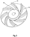
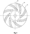
- the Figures 3 and 4 show the conveyor wheel 15 according to the in FIG. 1 illustrated embodiment of the invention.
- the conveying wheel 15 has eight conveying wings 16, each having a curvature and extending from the radially outer edge of the conveying wheel in the direction of a hub 18, wherein the radially inner end of the conveying wings 16 is spaced from the hub 18.
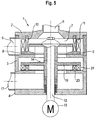
- FIG. 5 shows a mixing device 1 according to another embodiment of the present invention.
- the design in FIG. 5 differs from the embodiment in FIG. 1 in that the feed pump 14 is formed by a rotor / stator device with a rotor 19 and a stator 20.
- the rotor 19 comprises at least one rotor ring 21.
- a particularly fine dispersion is achieved. This is the case, in particular, when the mixture is recirculated, ie recirculated to the mixing process.
- FIG. 6 shows an embodiment of the invention with a further connection 22 between the conveyor module 3 and the mixing chamber 7.
- the further connection extends outside of a housing 23 on the outside, from a horizontal outer side of the conveyor module 3, to an outer side of the mixing module 2.
- the other Connection 22 forms a bypass line for the funded by the feed pump 14 liquid.
- additional connection and bypass line are used synonymously below.
- a portion of the conveyed liquid can bypass the conveying channel along the axis of the feed pump 14 between the conveyor module 3 and the mixing module 2 and pass directly into the mixing module 2 via the further connection 22.
- the further connection 22 is formed by a hose or pipe.
- the further connection 22 has an opening 24 leading into the mixing chamber 7.
- the mouth 24 is located on the opposite side of the mixing tool 8 - in the illustrated orientation at the top of the mixing chamber 7, so that the liquid gravity-assisted can enter into the mixing chamber 7.
- the mouth 24 is through an annular gap 25th educated.
- the annular gap 25 surrounds the feed slot 5 concentrically.
- the feed chute 5 is aligned with the axis of the mixing tool 8 in this embodiment.
- FIG. 7 shows an embodiment of the invention with an eccentric feed shaft 5 and an external bypass line 22.
- the feed shaft 5 is arranged with respect to the axis of the agitator 8 shifted.
- the opening 24 formed as an annular gap 25 of the bypass line 22 is widened within the housing 23 of the mixing device 1 so that the annular gap 25 also extends concentrically around the feed shaft 5 around.
- FIG. 8 shows an embodiment of the invention, wherein the bypass line forming further connection 22 within the housing 23 of the mixing device 1 along the conveying direction of the liquid - ascending in the illustrated orientation - from the conveyor module 3 to the mixing module 2 extends. Also, the mouth 24 is located completely inside the housing 23 of the mixing device 1. The bypass line 22 is completely integrated into the housing 23 of the mixing device 1 and forms a completely enclosed by the housing 23 channel.
- FIG. 9 shows an embodiment with an eccentric feed slot 5.
- the feed slot 5 is closed by a piston 26.
- the piston 26 is slidably disposed in the feed chute 5 along the feeding direction of the solid.
- the piston 26 is flush with the walls of the feed slot 5 and forms with the housing 23 and the mixing chamber 7 a closed cavity.
- the closure of the mixing chamber 7 is pressure-proof.
Landscapes
- Chemical & Material Sciences (AREA)
- Chemical Kinetics & Catalysis (AREA)
- Dispersion Chemistry (AREA)
- Mixers Of The Rotary Stirring Type (AREA)
- Structures Of Non-Positive Displacement Pumps (AREA)
- Accessories For Mixers (AREA)
Priority Applications (1)
| Application Number | Priority Date | Filing Date | Title |
|---|---|---|---|
| SI201531872T SI3505230T1 (sl) | 2015-02-04 | 2015-11-23 | Mešalna naprava z integrirano napajalno črpalko |
Applications Claiming Priority (4)
| Application Number | Priority Date | Filing Date | Title |
|---|---|---|---|
| DE102015101611 | 2015-02-04 | ||
| DE102015105247.4A DE102015105247B4 (de) | 2015-02-04 | 2015-04-07 | Mischvorrichtung mit integrierter Förderpumpe |
| EP15808333.7A EP3253480B1 (fr) | 2015-02-04 | 2015-11-23 | Dispositif de mélange à pompe d'alimentation intégrée |
| PCT/DE2015/100498 WO2016124164A1 (fr) | 2015-02-04 | 2015-11-23 | Dispositif de mélange à pompe d'alimentation intégrée |
Related Parent Applications (2)
| Application Number | Title | Priority Date | Filing Date |
|---|---|---|---|
| EP15808333.7A Division EP3253480B1 (fr) | 2015-02-04 | 2015-11-23 | Dispositif de mélange à pompe d'alimentation intégrée |
| EP15808333.7A Division-Into EP3253480B1 (fr) | 2015-02-04 | 2015-11-23 | Dispositif de mélange à pompe d'alimentation intégrée |
Publications (2)
| Publication Number | Publication Date |
|---|---|
| EP3505230A1 true EP3505230A1 (fr) | 2019-07-03 |
| EP3505230B1 EP3505230B1 (fr) | 2022-06-08 |
Family
ID=56410376
Family Applications (2)
| Application Number | Title | Priority Date | Filing Date |
|---|---|---|---|
| EP15808333.7A Active EP3253480B1 (fr) | 2015-02-04 | 2015-11-23 | Dispositif de mélange à pompe d'alimentation intégrée |
| EP19150614.6A Active EP3505230B1 (fr) | 2015-02-04 | 2015-11-23 | Dispositif de mélange à pompe de transport intégrée |
Family Applications Before (1)
| Application Number | Title | Priority Date | Filing Date |
|---|---|---|---|
| EP15808333.7A Active EP3253480B1 (fr) | 2015-02-04 | 2015-11-23 | Dispositif de mélange à pompe d'alimentation intégrée |
Country Status (13)
| Country | Link |
|---|---|
| US (1) | US10780406B2 (fr) |
| EP (2) | EP3253480B1 (fr) |
| JP (1) | JP6845797B2 (fr) |
| CN (1) | CN107438477B (fr) |
| BR (1) | BR112017015869B1 (fr) |
| CA (1) | CA2975776C (fr) |
| DE (2) | DE102015105247B4 (fr) |
| DK (2) | DK3505230T3 (fr) |
| ES (2) | ES2834613T3 (fr) |
| MX (1) | MX2017009692A (fr) |
| PL (2) | PL3505230T3 (fr) |
| SI (2) | SI3505230T1 (fr) |
| WO (1) | WO2016124164A1 (fr) |
Families Citing this family (9)
| Publication number | Priority date | Publication date | Assignee | Title |
|---|---|---|---|---|
| CN106925175B (zh) * | 2017-03-29 | 2019-10-15 | 南京辉锐光电科技有限公司 | 一种粉末混合装置及方法 |
| CN108993306B (zh) * | 2018-08-13 | 2021-06-25 | 苏州卓诚钛设备有限公司 | 一种内锁紧拆装式的同轴旋转药液搅拌装置 |
| DE102019102585A1 (de) * | 2019-02-01 | 2020-08-06 | Ystral Gmbh Maschinenbau + Processtechnik | Rotor für eine Vorrichtung zum Mischen von Pulver und Flüssigkeit und Vorrichtung zum Mischen von Pulver und Flüssigkeit |
| CN115666773A (zh) * | 2020-04-06 | 2023-01-31 | Prc-迪索托国际公司 | 用于密封剂料筒的混合叶轮 |
| CN111734690B (zh) * | 2020-07-23 | 2024-09-13 | 上海尼可尼流体系统有限公司 | 多相流体混合输送泵 |
| JP7760112B2 (ja) * | 2020-12-23 | 2025-10-27 | デンカ株式会社 | 連続混合装置 |
| CN113731259A (zh) * | 2021-08-05 | 2021-12-03 | 扬州大学附属医院 | 一种高分子材料研究用静电纺复合纤维膜制备设备 |
| CN219186528U (zh) * | 2022-12-09 | 2023-06-16 | 无锡理奇智能装备有限公司 | 液体分散结构总成及粉液混合装置 |
| CN117732361B (zh) * | 2024-02-21 | 2024-04-30 | 四川兆雪科技有限公司 | 一种高效高质量制备油气井示踪剂的装置及方法 |
Citations (5)
| Publication number | Priority date | Publication date | Assignee | Title |
|---|---|---|---|---|
| US3503846A (en) * | 1965-10-25 | 1970-03-31 | I C L Soc Agricola Ind Per La | Apparatus for bleaching wood pulp |
| DE19629945A1 (de) * | 1996-07-25 | 1998-01-29 | Janke & Kunkel Kg | Mischvorrichtung zum Vermischen von rieselfähigen Feststoffen mit wenigstens einer Flüssigkeit |
| EP1197260A1 (fr) * | 2000-10-11 | 2002-04-17 | Vakumix Rühr- und Homogenisiertechnik Aktiengesellschaft | Dispositif d'homogénéisation des matériaux fluides |
| EP1674151A1 (fr) * | 2004-12-23 | 2006-06-28 | Kinematica Ag | Dispositif pour la dispersion d'une substance liquide, solide ou bien gazeuse dans une liquide |
| EP2609998A1 (fr) * | 2011-12-26 | 2013-07-03 | Jtekt Corporation | Dispositif de dispersion |
Family Cites Families (7)
| Publication number | Priority date | Publication date | Assignee | Title |
|---|---|---|---|---|
| JPS5027178U (fr) * | 1973-07-10 | 1975-03-28 | ||
| US4239396A (en) * | 1979-01-25 | 1980-12-16 | Condor Engineering & Manufacturing, Inc. | Method and apparatus for blending liquids and solids |
| JP2681813B2 (ja) * | 1988-11-09 | 1997-11-26 | クニミネ工業株式会社 | 分散液調製装置 |
| JP3862241B2 (ja) * | 1995-12-16 | 2006-12-27 | 光洋機械産業株式会社 | ミキサ−の原料投入装置 |
| CN101516488B (zh) * | 2006-09-21 | 2013-06-19 | 巴斯夫欧洲公司 | 混合具有细粒固体的密闭容器中的液体的方法,这种容器,喷射器喷射嘴以及这种喷射嘴的用途 |
| JP2013132572A (ja) * | 2011-12-26 | 2013-07-08 | Jtekt Corp | 混合分散装置 |
| CN103977721B (zh) * | 2014-05-30 | 2015-10-21 | 济钢集团有限公司 | 一种储槽内固液混合介质循环搅拌系统 |
-
2015
- 2015-04-07 DE DE102015105247.4A patent/DE102015105247B4/de active Active
- 2015-11-23 SI SI201531872T patent/SI3505230T1/sl unknown
- 2015-11-23 DK DK19150614.6T patent/DK3505230T3/da active
- 2015-11-23 MX MX2017009692A patent/MX2017009692A/es unknown
- 2015-11-23 EP EP15808333.7A patent/EP3253480B1/fr active Active
- 2015-11-23 SI SI201531422T patent/SI3253480T1/sl unknown
- 2015-11-23 JP JP2017540853A patent/JP6845797B2/ja active Active
- 2015-11-23 ES ES15808333T patent/ES2834613T3/es active Active
- 2015-11-23 CA CA2975776A patent/CA2975776C/fr active Active
- 2015-11-23 US US15/547,683 patent/US10780406B2/en active Active
- 2015-11-23 PL PL19150614.6T patent/PL3505230T3/pl unknown
- 2015-11-23 EP EP19150614.6A patent/EP3505230B1/fr active Active
- 2015-11-23 PL PL15808333T patent/PL3253480T3/pl unknown
- 2015-11-23 WO PCT/DE2015/100498 patent/WO2016124164A1/fr not_active Ceased
- 2015-11-23 ES ES19150614T patent/ES2926340T3/es active Active
- 2015-11-23 CN CN201580074945.0A patent/CN107438477B/zh active Active
- 2015-11-23 DE DE112015006108.8T patent/DE112015006108A5/de not_active Withdrawn
- 2015-11-23 DK DK15808333.7T patent/DK3253480T3/da active
- 2015-11-23 BR BR112017015869-8A patent/BR112017015869B1/pt active IP Right Grant
Patent Citations (5)
| Publication number | Priority date | Publication date | Assignee | Title |
|---|---|---|---|---|
| US3503846A (en) * | 1965-10-25 | 1970-03-31 | I C L Soc Agricola Ind Per La | Apparatus for bleaching wood pulp |
| DE19629945A1 (de) * | 1996-07-25 | 1998-01-29 | Janke & Kunkel Kg | Mischvorrichtung zum Vermischen von rieselfähigen Feststoffen mit wenigstens einer Flüssigkeit |
| EP1197260A1 (fr) * | 2000-10-11 | 2002-04-17 | Vakumix Rühr- und Homogenisiertechnik Aktiengesellschaft | Dispositif d'homogénéisation des matériaux fluides |
| EP1674151A1 (fr) * | 2004-12-23 | 2006-06-28 | Kinematica Ag | Dispositif pour la dispersion d'une substance liquide, solide ou bien gazeuse dans une liquide |
| EP2609998A1 (fr) * | 2011-12-26 | 2013-07-03 | Jtekt Corporation | Dispositif de dispersion |
Also Published As
| Publication number | Publication date |
|---|---|
| JP2018510054A (ja) | 2018-04-12 |
| CA2975776A1 (fr) | 2016-08-11 |
| EP3505230B1 (fr) | 2022-06-08 |
| PL3505230T3 (pl) | 2022-10-03 |
| CN107438477A (zh) | 2017-12-05 |
| DK3253480T3 (da) | 2020-12-14 |
| DE102015105247A1 (de) | 2016-08-04 |
| ES2834613T3 (es) | 2021-06-18 |
| MX2017009692A (es) | 2017-10-23 |
| EP3253480A1 (fr) | 2017-12-13 |
| EP3253480B1 (fr) | 2020-09-23 |
| SI3253480T1 (sl) | 2021-04-30 |
| DE112015006108A5 (de) | 2018-04-12 |
| US10780406B2 (en) | 2020-09-22 |
| DK3505230T3 (da) | 2022-09-05 |
| US20180264419A1 (en) | 2018-09-20 |
| CA2975776C (fr) | 2023-02-28 |
| CN107438477B (zh) | 2021-07-09 |
| DE102015105247B4 (de) | 2018-02-01 |
| BR112017015869B1 (pt) | 2022-09-13 |
| BR112017015869A2 (pt) | 2018-03-27 |
| ES2926340T3 (es) | 2022-10-25 |
| JP6845797B2 (ja) | 2021-03-24 |
| WO2016124164A1 (fr) | 2016-08-11 |
| PL3253480T3 (pl) | 2021-03-08 |
| SI3505230T1 (sl) | 2022-11-30 |
Similar Documents
| Publication | Publication Date | Title |
|---|---|---|
| EP3505230B1 (fr) | Dispositif de mélange à pompe de transport intégrée | |
| CN108355569B (zh) | 制备超细浆料的固液混合装置 | |
| EP2572777B1 (fr) | Moyen de sortie pour disperseur à rotor-stator | |
| EP1674151B1 (fr) | Dispositif pour la dispersion d'une substance liquide, solide ou bien gazeuse dans une liquide | |
| WO2001080985A1 (fr) | Element de melange statique | |
| EP3202489B1 (fr) | Dispositif destiné à homogénéiser et/ou disperser des produits fluides | |
| WO2013127534A1 (fr) | Dispositif permettant de mélanger au moins deux composants fluides, organe rotatif amovible pour mélangeurs, et système formé par ces deux éléments | |
| EP2035126B1 (fr) | Dispositif homogénéisateur avec des couronnes dentées logées horizontalement | |
| WO1992021436A1 (fr) | Dispositif de dispersion, suspension ou emulsion de gaz, liquides et/ou matieres solides coulantes | |
| DE102016100896B3 (de) | Vorrichtung zum Herstellen einer Lösung | |
| EP1792643B1 (fr) | Réacteur à grand volume respectivement évaporateur à couche mince combiné avec un dispositif pré-melangeur | |
| EP4357013A1 (fr) | Procédé et mélangeur colloïdal pour la préparation colloïdale d'une suspension | |
| EP2004315B1 (fr) | Homogeneiseur comportant un rotor, un inducteur (vis inducteur) pouvant tourner dans le sens oppose au rotor et un rotor a contre-courant pouvant tourner en direction opposee au rotor | |
| DE102007005622A1 (de) | Vorrichtung und Verfahren zur kontinuierlichen Herstellung einer Mischung aus wenigstens zwei fließfähigen Phasen | |
| WO2017025073A1 (fr) | Dispositif et procédé destinés à la dispersion d'au moins une substance dans un fluide | |
| DE102015121513A1 (de) | Rührvorrichtung | |
| EP2818234B1 (fr) | Dispositif de stockage de milieux semi-liquides | |
| DE102005007175A1 (de) | Vorrichtung und Verfahren zum Homogenisieren | |
| EP4259319A1 (fr) | Dispositif de dispersion de milieux, en particulier d'une substance dans un liquide | |
| DE4133604C2 (de) | Vorrichtung zum Fördern und Mischen eines Feststoffes mit einer Flüssigkeit | |
| DE20214291U1 (de) | Rühr-Vorrichtung für hochviskose Medien | |
| DE202014003774U1 (de) | Vorrichtung zum Homogenisieren und/oder Dispergieren fließfähiger Produkte | |
| DE60316199T2 (de) | Vakuumpumpe | |
| EP3192582A1 (fr) | Outil pour un mélangeur et mélangeur | |
| DE4020508A1 (de) | Dispergieranlage |
Legal Events
| Date | Code | Title | Description |
|---|---|---|---|
| PUAI | Public reference made under article 153(3) epc to a published international application that has entered the european phase |
Free format text: ORIGINAL CODE: 0009012 |
|
| STAA | Information on the status of an ep patent application or granted ep patent |
Free format text: STATUS: THE APPLICATION HAS BEEN PUBLISHED |
|
| AC | Divisional application: reference to earlier application |
Ref document number: 3253480 Country of ref document: EP Kind code of ref document: P |
|
| AK | Designated contracting states |
Kind code of ref document: A1 Designated state(s): AL AT BE BG CH CY CZ DE DK EE ES FI FR GB GR HR HU IE IS IT LI LT LU LV MC MK MT NL NO PL PT RO RS SE SI SK SM TR |
|
| STAA | Information on the status of an ep patent application or granted ep patent |
Free format text: STATUS: REQUEST FOR EXAMINATION WAS MADE |
|
| 17P | Request for examination filed |
Effective date: 20190805 |
|
| RBV | Designated contracting states (corrected) |
Designated state(s): AL AT BE BG CH CY CZ DE DK EE ES FI FR GB GR HR HU IE IS IT LI LT LU LV MC MK MT NL NO PL PT RO RS SE SI SK SM TR |
|
| STAA | Information on the status of an ep patent application or granted ep patent |
Free format text: STATUS: EXAMINATION IS IN PROGRESS |
|
| 17Q | First examination report despatched |
Effective date: 20200225 |
|
| REG | Reference to a national code |
Ref country code: DE Ref legal event code: R079 Ref document number: 502015015891 Country of ref document: DE Free format text: PREVIOUS MAIN CLASS: B01F0003120000 Ipc: B01F0023530000 |
|
| GRAP | Despatch of communication of intention to grant a patent |
Free format text: ORIGINAL CODE: EPIDOSNIGR1 |
|
| STAA | Information on the status of an ep patent application or granted ep patent |
Free format text: STATUS: GRANT OF PATENT IS INTENDED |
|
| RIC1 | Information provided on ipc code assigned before grant |
Ipc: B01F 35/71 20220101ALI20220106BHEP Ipc: B01F 35/00 20220101ALI20220106BHEP Ipc: B01F 27/271 20220101ALI20220106BHEP Ipc: B01F 25/52 20220101ALI20220106BHEP Ipc: B01F 23/53 20220101AFI20220106BHEP |
|
| INTG | Intention to grant announced |
Effective date: 20220201 |
|
| GRAS | Grant fee paid |
Free format text: ORIGINAL CODE: EPIDOSNIGR3 |
|
| GRAA | (expected) grant |
Free format text: ORIGINAL CODE: 0009210 |
|
| STAA | Information on the status of an ep patent application or granted ep patent |
Free format text: STATUS: THE PATENT HAS BEEN GRANTED |
|
| AC | Divisional application: reference to earlier application |
Ref document number: 3253480 Country of ref document: EP Kind code of ref document: P |
|
| AK | Designated contracting states |
Kind code of ref document: B1 Designated state(s): AL AT BE BG CH CY CZ DE DK EE ES FI FR GB GR HR HU IE IS IT LI LT LU LV MC MK MT NL NO PL PT RO RS SE SI SK SM TR |
|
| REG | Reference to a national code |
Ref country code: AT Ref legal event code: REF Ref document number: 1496533 Country of ref document: AT Kind code of ref document: T Effective date: 20220615 Ref country code: CH Ref legal event code: EP |
|
| REG | Reference to a national code |
Ref country code: DE Ref legal event code: R096 Ref document number: 502015015891 Country of ref document: DE |
|
| REG | Reference to a national code |
Ref country code: IE Ref legal event code: FG4D Free format text: LANGUAGE OF EP DOCUMENT: GERMAN |
|
| REG | Reference to a national code |
Ref country code: NL Ref legal event code: FP |
|
| REG | Reference to a national code |
Ref country code: FI Ref legal event code: FGE |
|
| REG | Reference to a national code |
Ref country code: DK Ref legal event code: T3 Effective date: 20220830 |
|
| REG | Reference to a national code |
Ref country code: SE Ref legal event code: TRGR |
|
| REG | Reference to a national code |
Ref country code: LT Ref legal event code: MG9D |
|
| REG | Reference to a national code |
Ref country code: NO Ref legal event code: T2 Effective date: 20220608 |
|
| REG | Reference to a national code |
Ref country code: ES Ref legal event code: FG2A Ref document number: 2926340 Country of ref document: ES Kind code of ref document: T3 Effective date: 20221025 |
|
| PG25 | Lapsed in a contracting state [announced via postgrant information from national office to epo] |
Ref country code: LT Free format text: LAPSE BECAUSE OF FAILURE TO SUBMIT A TRANSLATION OF THE DESCRIPTION OR TO PAY THE FEE WITHIN THE PRESCRIBED TIME-LIMIT Effective date: 20220608 Ref country code: HR Free format text: LAPSE BECAUSE OF FAILURE TO SUBMIT A TRANSLATION OF THE DESCRIPTION OR TO PAY THE FEE WITHIN THE PRESCRIBED TIME-LIMIT Effective date: 20220608 Ref country code: GR Free format text: LAPSE BECAUSE OF FAILURE TO SUBMIT A TRANSLATION OF THE DESCRIPTION OR TO PAY THE FEE WITHIN THE PRESCRIBED TIME-LIMIT Effective date: 20220909 Ref country code: BG Free format text: LAPSE BECAUSE OF FAILURE TO SUBMIT A TRANSLATION OF THE DESCRIPTION OR TO PAY THE FEE WITHIN THE PRESCRIBED TIME-LIMIT Effective date: 20220908 |
|
| PG25 | Lapsed in a contracting state [announced via postgrant information from national office to epo] |
Ref country code: RS Free format text: LAPSE BECAUSE OF FAILURE TO SUBMIT A TRANSLATION OF THE DESCRIPTION OR TO PAY THE FEE WITHIN THE PRESCRIBED TIME-LIMIT Effective date: 20220608 Ref country code: LV Free format text: LAPSE BECAUSE OF FAILURE TO SUBMIT A TRANSLATION OF THE DESCRIPTION OR TO PAY THE FEE WITHIN THE PRESCRIBED TIME-LIMIT Effective date: 20220608 |
|
| PG25 | Lapsed in a contracting state [announced via postgrant information from national office to epo] |
Ref country code: SM Free format text: LAPSE BECAUSE OF FAILURE TO SUBMIT A TRANSLATION OF THE DESCRIPTION OR TO PAY THE FEE WITHIN THE PRESCRIBED TIME-LIMIT Effective date: 20220608 Ref country code: SK Free format text: LAPSE BECAUSE OF FAILURE TO SUBMIT A TRANSLATION OF THE DESCRIPTION OR TO PAY THE FEE WITHIN THE PRESCRIBED TIME-LIMIT Effective date: 20220608 Ref country code: RO Free format text: LAPSE BECAUSE OF FAILURE TO SUBMIT A TRANSLATION OF THE DESCRIPTION OR TO PAY THE FEE WITHIN THE PRESCRIBED TIME-LIMIT Effective date: 20220608 Ref country code: PT Free format text: LAPSE BECAUSE OF FAILURE TO SUBMIT A TRANSLATION OF THE DESCRIPTION OR TO PAY THE FEE WITHIN THE PRESCRIBED TIME-LIMIT Effective date: 20221010 Ref country code: EE Free format text: LAPSE BECAUSE OF FAILURE TO SUBMIT A TRANSLATION OF THE DESCRIPTION OR TO PAY THE FEE WITHIN THE PRESCRIBED TIME-LIMIT Effective date: 20220608 |
|
| PG25 | Lapsed in a contracting state [announced via postgrant information from national office to epo] |
Ref country code: IS Free format text: LAPSE BECAUSE OF FAILURE TO SUBMIT A TRANSLATION OF THE DESCRIPTION OR TO PAY THE FEE WITHIN THE PRESCRIBED TIME-LIMIT Effective date: 20221008 |
|
| REG | Reference to a national code |
Ref country code: DE Ref legal event code: R097 Ref document number: 502015015891 Country of ref document: DE |
|
| PG25 | Lapsed in a contracting state [announced via postgrant information from national office to epo] |
Ref country code: AL Free format text: LAPSE BECAUSE OF FAILURE TO SUBMIT A TRANSLATION OF THE DESCRIPTION OR TO PAY THE FEE WITHIN THE PRESCRIBED TIME-LIMIT Effective date: 20220608 |
|
| PLBE | No opposition filed within time limit |
Free format text: ORIGINAL CODE: 0009261 |
|
| STAA | Information on the status of an ep patent application or granted ep patent |
Free format text: STATUS: NO OPPOSITION FILED WITHIN TIME LIMIT |
|
| 26N | No opposition filed |
Effective date: 20230310 |
|
| PG25 | Lapsed in a contracting state [announced via postgrant information from national office to epo] |
Ref country code: MC Free format text: LAPSE BECAUSE OF FAILURE TO SUBMIT A TRANSLATION OF THE DESCRIPTION OR TO PAY THE FEE WITHIN THE PRESCRIBED TIME-LIMIT Effective date: 20220608 |
|
| PG25 | Lapsed in a contracting state [announced via postgrant information from national office to epo] |
Ref country code: LU Free format text: LAPSE BECAUSE OF NON-PAYMENT OF DUE FEES Effective date: 20221123 |
|
| PG25 | Lapsed in a contracting state [announced via postgrant information from national office to epo] |
Ref country code: HU Free format text: LAPSE BECAUSE OF FAILURE TO SUBMIT A TRANSLATION OF THE DESCRIPTION OR TO PAY THE FEE WITHIN THE PRESCRIBED TIME-LIMIT; INVALID AB INITIO Effective date: 20151123 |
|
| PG25 | Lapsed in a contracting state [announced via postgrant information from national office to epo] |
Ref country code: CY Free format text: LAPSE BECAUSE OF FAILURE TO SUBMIT A TRANSLATION OF THE DESCRIPTION OR TO PAY THE FEE WITHIN THE PRESCRIBED TIME-LIMIT Effective date: 20220608 |
|
| PG25 | Lapsed in a contracting state [announced via postgrant information from national office to epo] |
Ref country code: MK Free format text: LAPSE BECAUSE OF FAILURE TO SUBMIT A TRANSLATION OF THE DESCRIPTION OR TO PAY THE FEE WITHIN THE PRESCRIBED TIME-LIMIT Effective date: 20220608 |
|
| PG25 | Lapsed in a contracting state [announced via postgrant information from national office to epo] |
Ref country code: MT Free format text: LAPSE BECAUSE OF FAILURE TO SUBMIT A TRANSLATION OF THE DESCRIPTION OR TO PAY THE FEE WITHIN THE PRESCRIBED TIME-LIMIT Effective date: 20220608 |
|
| PG25 | Lapsed in a contracting state [announced via postgrant information from national office to epo] |
Ref country code: BG Free format text: LAPSE BECAUSE OF FAILURE TO SUBMIT A TRANSLATION OF THE DESCRIPTION OR TO PAY THE FEE WITHIN THE PRESCRIBED TIME-LIMIT Effective date: 20220608 |
|
| PG25 | Lapsed in a contracting state [announced via postgrant information from national office to epo] |
Ref country code: BG Free format text: LAPSE BECAUSE OF FAILURE TO SUBMIT A TRANSLATION OF THE DESCRIPTION OR TO PAY THE FEE WITHIN THE PRESCRIBED TIME-LIMIT Effective date: 20220608 |
|
| REG | Reference to a national code |
Ref country code: CH Ref legal event code: U11 Free format text: ST27 STATUS EVENT CODE: U-0-0-U10-U11 (AS PROVIDED BY THE NATIONAL OFFICE) Effective date: 20251201 |
|
| PGFP | Annual fee paid to national office [announced via postgrant information from national office to epo] |
Ref country code: NL Payment date: 20251119 Year of fee payment: 11 |
|
| PGFP | Annual fee paid to national office [announced via postgrant information from national office to epo] |
Ref country code: GB Payment date: 20251120 Year of fee payment: 11 |
|
| PGFP | Annual fee paid to national office [announced via postgrant information from national office to epo] |
Ref country code: NO Payment date: 20251118 Year of fee payment: 11 |
|
| PGFP | Annual fee paid to national office [announced via postgrant information from national office to epo] |
Ref country code: AT Payment date: 20251117 Year of fee payment: 11 |
|
| PGFP | Annual fee paid to national office [announced via postgrant information from national office to epo] |
Ref country code: IT Payment date: 20251128 Year of fee payment: 11 Ref country code: FI Payment date: 20251118 Year of fee payment: 11 Ref country code: DK Payment date: 20251119 Year of fee payment: 11 |
|
| PGFP | Annual fee paid to national office [announced via postgrant information from national office to epo] |
Ref country code: FR Payment date: 20251125 Year of fee payment: 11 |
|
| PGFP | Annual fee paid to national office [announced via postgrant information from national office to epo] |
Ref country code: TR Payment date: 20251117 Year of fee payment: 11 Ref country code: BE Payment date: 20251118 Year of fee payment: 11 |
|
| PGFP | Annual fee paid to national office [announced via postgrant information from national office to epo] |
Ref country code: CH Payment date: 20251201 Year of fee payment: 11 Ref country code: SE Payment date: 20251119 Year of fee payment: 11 |
|
| PGFP | Annual fee paid to national office [announced via postgrant information from national office to epo] |
Ref country code: IE Payment date: 20251120 Year of fee payment: 11 Ref country code: CZ Payment date: 20251107 Year of fee payment: 11 |
|
| PGFP | Annual fee paid to national office [announced via postgrant information from national office to epo] |
Ref country code: PL Payment date: 20251107 Year of fee payment: 11 |
|
| PGFP | Annual fee paid to national office [announced via postgrant information from national office to epo] |
Ref country code: SI Payment date: 20251111 Year of fee payment: 11 Ref country code: ES Payment date: 20251216 Year of fee payment: 11 |
|
| PGFP | Annual fee paid to national office [announced via postgrant information from national office to epo] |
Ref country code: DE Payment date: 20251223 Year of fee payment: 11 |