EP3506236B1 - Fahrzeugzustandssteuerungsvorrichtung und -verfahren sowie fahrzeug - Google Patents
Fahrzeugzustandssteuerungsvorrichtung und -verfahren sowie fahrzeug Download PDFInfo
- Publication number
- EP3506236B1 EP3506236B1 EP17843433.8A EP17843433A EP3506236B1 EP 3506236 B1 EP3506236 B1 EP 3506236B1 EP 17843433 A EP17843433 A EP 17843433A EP 3506236 B1 EP3506236 B1 EP 3506236B1
- Authority
- EP
- European Patent Office
- Prior art keywords
- vehicle
- state
- window
- drive
- area
- Prior art date
- Legal status (The legal status is an assumption and is not a legal conclusion. Google has not performed a legal analysis and makes no representation as to the accuracy of the status listed.)
- Not-in-force
Links
Images




Classifications
-
- B—PERFORMING OPERATIONS; TRANSPORTING
- B60—VEHICLES IN GENERAL
- B60W—CONJOINT CONTROL OF VEHICLE SUB-UNITS OF DIFFERENT TYPE OR DIFFERENT FUNCTION; CONTROL SYSTEMS SPECIALLY ADAPTED FOR HYBRID VEHICLES; ROAD VEHICLE DRIVE CONTROL SYSTEMS FOR PURPOSES NOT RELATED TO THE CONTROL OF A PARTICULAR SUB-UNIT
- B60W30/00—Purposes of road vehicle drive control systems not related to the control of a particular sub-unit, e.g. of systems using conjoint control of vehicle sub-units
- B60W30/18—Propelling the vehicle
- B60W30/18009—Propelling the vehicle related to particular drive situations
-
- B—PERFORMING OPERATIONS; TRANSPORTING
- B62—LAND VEHICLES FOR TRAVELLING OTHERWISE THAN ON RAILS
- B62D—MOTOR VEHICLES; TRAILERS
- B62D15/00—Steering not otherwise provided for
- B62D15/02—Steering position indicators ; Steering position determination; Steering aids
- B62D15/027—Parking aids, e.g. instruction means
- B62D15/0285—Parking performed automatically
-
- E—FIXED CONSTRUCTIONS
- E05—LOCKS; KEYS; WINDOW OR DOOR FITTINGS; SAFES
- E05F—DEVICES FOR MOVING WINGS INTO OPEN OR CLOSED POSITION; CHECKS FOR WINGS; WING FITTINGS NOT OTHERWISE PROVIDED FOR, CONCERNED WITH THE FUNCTIONING OF THE WING
- E05F15/00—Power-operated mechanisms for wings
- E05F15/70—Power-operated mechanisms for wings with automatic actuation
-
- G—PHYSICS
- G05—CONTROLLING; REGULATING
- G05D—SYSTEMS FOR CONTROLLING OR REGULATING NON-ELECTRIC VARIABLES
- G05D1/00—Control of position, course, altitude or attitude of land, water, air or space vehicles, e.g. using automatic pilots
- G05D1/02—Control of position or course in two dimensions
- G05D1/021—Control of position or course in two dimensions specially adapted to land vehicles
- G05D1/0231—Control of position or course in two dimensions specially adapted to land vehicles using optical position detecting means
- G05D1/0246—Control of position or course in two dimensions specially adapted to land vehicles using optical position detecting means using a video camera in combination with image processing means
- G05D1/0248—Control of position or course in two dimensions specially adapted to land vehicles using optical position detecting means using a video camera in combination with image processing means in combination with a laser
-
- G—PHYSICS
- G05—CONTROLLING; REGULATING
- G05D—SYSTEMS FOR CONTROLLING OR REGULATING NON-ELECTRIC VARIABLES
- G05D1/00—Control of position, course, altitude or attitude of land, water, air or space vehicles, e.g. using automatic pilots
- G05D1/02—Control of position or course in two dimensions
- G05D1/021—Control of position or course in two dimensions specially adapted to land vehicles
- G05D1/0257—Control of position or course in two dimensions specially adapted to land vehicles using a radar
-
- G—PHYSICS
- G06—COMPUTING OR CALCULATING; COUNTING
- G06Q—INFORMATION AND COMMUNICATION TECHNOLOGY [ICT] SPECIALLY ADAPTED FOR ADMINISTRATIVE, COMMERCIAL, FINANCIAL, MANAGERIAL OR SUPERVISORY PURPOSES; SYSTEMS OR METHODS SPECIALLY ADAPTED FOR ADMINISTRATIVE, COMMERCIAL, FINANCIAL, MANAGERIAL OR SUPERVISORY PURPOSES, NOT OTHERWISE PROVIDED FOR
- G06Q30/00—Commerce
- G06Q30/06—Buying, selling or leasing transactions
-
- G—PHYSICS
- G06—COMPUTING OR CALCULATING; COUNTING
- G06V—IMAGE OR VIDEO RECOGNITION OR UNDERSTANDING
- G06V20/00—Scenes; Scene-specific elements
- G06V20/50—Context or environment of the image
- G06V20/56—Context or environment of the image exterior to a vehicle by using sensors mounted on the vehicle
-
- G—PHYSICS
- G08—SIGNALLING
- G08G—TRAFFIC CONTROL SYSTEMS
- G08G1/00—Traffic control systems for road vehicles
- G08G1/09—Arrangements for giving variable traffic instructions
-
- G—PHYSICS
- G08—SIGNALLING
- G08G—TRAFFIC CONTROL SYSTEMS
- G08G1/00—Traffic control systems for road vehicles
- G08G1/16—Anti-collision systems
-
- B—PERFORMING OPERATIONS; TRANSPORTING
- B60—VEHICLES IN GENERAL
- B60W—CONJOINT CONTROL OF VEHICLE SUB-UNITS OF DIFFERENT TYPE OR DIFFERENT FUNCTION; CONTROL SYSTEMS SPECIALLY ADAPTED FOR HYBRID VEHICLES; ROAD VEHICLE DRIVE CONTROL SYSTEMS FOR PURPOSES NOT RELATED TO THE CONTROL OF A PARTICULAR SUB-UNIT
- B60W2540/00—Input parameters relating to occupants
- B60W2540/049—Number of occupants
-
- B—PERFORMING OPERATIONS; TRANSPORTING
- B60—VEHICLES IN GENERAL
- B60W—CONJOINT CONTROL OF VEHICLE SUB-UNITS OF DIFFERENT TYPE OR DIFFERENT FUNCTION; CONTROL SYSTEMS SPECIALLY ADAPTED FOR HYBRID VEHICLES; ROAD VEHICLE DRIVE CONTROL SYSTEMS FOR PURPOSES NOT RELATED TO THE CONTROL OF A PARTICULAR SUB-UNIT
- B60W2540/00—Input parameters relating to occupants
- B60W2540/227—Position in the vehicle
-
- E—FIXED CONSTRUCTIONS
- E05—LOCKS; KEYS; WINDOW OR DOOR FITTINGS; SAFES
- E05Y—INDEXING SCHEME ASSOCIATED WITH SUBCLASSES E05D AND E05F, RELATING TO CONSTRUCTION ELEMENTS, ELECTRIC CONTROL, POWER SUPPLY, POWER SIGNAL OR TRANSMISSION, USER INTERFACES, MOUNTING OR COUPLING, DETAILS, ACCESSORIES, AUXILIARY OPERATIONS NOT OTHERWISE PROVIDED FOR, APPLICATION THEREOF
- E05Y2900/00—Application of doors, windows, wings or fittings thereof
- E05Y2900/50—Application of doors, windows, wings or fittings thereof for vehicles
- E05Y2900/53—Type of wing
- E05Y2900/55—Windows
Definitions
- the present invention relates to a vehicle state control apparatus, a vehicle state control method, and a vehicle, and particularly to a vehicle state control apparatus, a vehicle state control method, and a vehicle that make it possible to perform driving assistant in a drive-through area.
- Patent Literature 1 Japanese Patent Application Laid-open No. 2007-183824
- JP 2004 355145 A discloses a vehicle controller.
- JP H11 296798 A discloses a vehicle safe passage system.
- JP 2009 113685 A discloses a following traveling control system.
- WO 2015/057144 A1 discloses a method for stopping a motor vehicle comprising the step of activating a vehicle-controlled stopping process during which the vehicle is controlled automatically. The method further comprises the step of controlling the stopping process while taking into account a passenger perspective that includes taking considerations of passenger comfort into account.
- a drive-through is ordinarily used as a function that provides products and services while the customer is in an automobile, and the facility therefor, and automatic driving and driving assistant are desired also in the drive-through area.
- the present invention has been made in view of the above-mentioned circumstances to make it possible to perform driving assistant in a drive-through area.
- a vehicle state control apparatus includes: a vehicle entering/leaving detection unit that detects being in a drive-through area; and a control unit that controls a state of a vehicle in the drive-through area detected by the vehicle entering/leaving detection unit.
- the control unit may control a travelling state of the vehicle as the state of the vehicle
- the vehicle state control apparatus further includes a riding state detection unit that detects a riding state of the vehicle.
- the control unit stops the vehicle at at least one of an order window, a pick-up window, or a payment window, as the travelling state of the vehicle.
- the control unit stops the vehicle at a position, corresponding to the riding state of the vehicle at the at least one window, as the travelling state of the vehicle.
- the control unit may control, where a service at the at least one window is finished, travelling of the vehicle stopped as the travelling state of the vehicle.
- the vehicle state control apparatus may further include a service completion detection unit that detects completion of a service, in which the control unit may control, in accordance with a detection result of the completion of the service by the service completion detection unit, the travelling of the vehicle stopped as the travelling state of the vehicle.
- the control unit may cause, where the completion of the service is detected by the service completion detection unit, the vehicle stopped as the travelling state of the vehicle to start travelling.
- the service may be a payment service.
- the control unit may control, where being in the drive-through area is detected by the vehicle entering/leaving detection unit or the vehicle is stopped at the at least one window, opening/closing of a window of the vehicle as the state of the vehicle.
- the control unit may control the opening/closing of the window of the vehicle, corresponding to weather.
- the control unit may control the opening/closing of the window of the vehicle, corresponding to a security state.
- the control unit may close the opened window of the vehicle on a condition that the service at the at least one window is finished or services at all the windows are finished.
- the control unit may notify, where being in the drive-through area is detected by the vehicle entering/leaving detection unit, a user of presentation for selecting whether to set a mode of the vehicle to a drive-through area mode that is a driving assistant mode in the drive-through area.
- the vehicle entering/leaving detection unit may detect, where the drive-through area mode is set, leaving the drive-through area, and the control unit may notify, where leaving the drive-through area is detected by the vehicle entering/leaving detection unit, the user of presentation regarding whether to release the drive-through area mode of the vehicle.
- a vehicle state control method includes: by a vehicle state control apparatus, detecting being in a drive-through area; and controlling a state of a vehicle in the detected drive-through area.
- a vehicle detects being in a drive-through area; and controls a state of the vehicle in the drive-through area detected by the vehicle entering/leaving detection unit.
- the state of the vehicle is controlled in the detected drive-through area.
- embodiments for carrying out the present invention (hereinafter, referred to as embodiments) will be described.
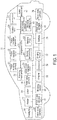
- Fig. 1 is a diagram showing a configuration example of an embodiment of a vehicle to which the present technology is applied.
- a vehicle 11 shown in Fig. 1 includes a front sensing camera 21, a front camera ECU (Electronic Control Unit) 22, a position information acquisition unit 23, a display unit 24, a communication unit 25, a steering mechanism 26,a radar 27, a lidar (LIDAR) 28, a side view camera 29, a side view camera ECU 30, an integrated ECU 31, a front view camera 32, a front view camera ECU 33, a braking device 34, an engine 35, a generator 36, a driving motor 37, a battery 38, a rear view camera 39, a rear view camera ECU 40, and a speed detection unit 41. Further, the vehicle 11 includes also an in-vehicle sensor 42, a window control unit 43, and a headlight 44.
- the units provided in the vehicle 11 are connected to each other by a bus for CAN (Controller Area Network) communication, another connection line, and the like.
- CAN Controller Area Network
- the bus, the connection line, and the like are drawn without particularly distinguishing them.
- the front sensing camera 21 includes, for example, a camera dedicated to sensing disposed in the vicinity of a room mirror in the vehicle, images the front of the vehicle 11 as a subject, and outputs the resulting sensing image to the front camera ECU 22.
- the front camera ECU 22 appropriately performs processing of improving the image quality or the like on the sensing image supplied from the front sensing camera 21, and then performs image recognition on the sensing image, thereby detecting an arbitrary object such as a white line and a pedestrian from the sensing image.
- the front camera ECU 22 outputs the result of image recognition to the bus for CAN communication.
- the position information acquisition unit 23 includes, for example, a position information measuring system such as a GPS (Global Positioning System), detects the position of the vehicle 11, and outputs the position information indicating the detection result to the bus for CAN communication.
- a position information measuring system such as a GPS (Global Positioning System)
- GPS Global Positioning System
- the display unit 24 includes, for example, a liquid crystal display panel, and is disposed at a predetermined position in the vehicle such as the center position of an instrument panel and the inside of a room mirror. Further, the display unit 24 may be a transmissive display superimposed and provided on a windshield part, or a display of a car navigation system. The display unit 24 displays various images under the control of the integrated ECU 31.
- the communication unit 25 transmits/receives information to/from a peripheral vehicle, a portable terminal device possessed by a pedestrian, a roadside device, or an external server by various kinds of wireless communication such as inter-vehicle communication, vehicle-to-pedestrian communication, and road-to-vehicle communication.
- the communication unit 25 performs inter-vehicle communication with a peripheral vehicle, receives, from the peripheral vehicle, peripheral vehicle information including information indicating the number of occupants and the travelling state, and supplies it to the integrated ECU 31.
- the steering mechanism 26 performs control of the traveling direction of the vehicle 11, i.e., steering angle control, in accordance with the driver's steering wheel operation or the control signal supplied from the integrated ECU 31.
- the radar 27 is a distance measuring sensor that measures the distance to an object such as a vehicle and a pedestrian in each direction such as forward and backward by using electromagnetic waves such as millimeter waves, and outputs the result of measuring the distance to the object to the integrated ECU 31 or the like.
- the lidar 28 is a distance measuring sensor that measures the distance to an object such as a vehicle and a pedestrian in each direction such as forward and backward by using light waves, and outputs the result of measuring the distance to the object to the integrated ECU 31 or the like.
- the side view camera 29 is, for example, a camera disposed in a casing of a side mirror or in the vicinity of the side mirror, captures an image of the side (hereinafter, referred to also as the side image) of the vehicle 11 including an area to be a blind spot of the driver, and supplies it to the side view camera ECU 30.
- the side view camera ECU 30 performs image processing of improving the image quality such as white balance adjustment on the side image supplied from the side view camera 29, and supplies the obtained side image to the integrated ECU 31 via a cable different from the bus for CAN communication.
- the integrated ECU 31 includes a plurality of ECUs such as a driving control ECU 51 and a battery ECU 52 arranged at the center of the vehicle 11, and controls the operation of the entire vehicle 11.
- the driving control ECU 51 is an ECU realizing an ADAS (Advanced Driving Assistant System) function or an automated driving (Self driving) function, and controls the driving (travelling) of the vehicle 11 on the basis of various kinds of information such as the image recognition result from the front camera ECU 22, the position information from the position information acquisition unit 23, the peripheral vehicle information supplied from the communication unit 25, the measurement results from the radar 27 and the lidar 28, the result of detecting the travelling speed from the speed detection unit 41, and the like. That is, the driving control ECU 51 controls the steering mechanism 26, the braking device 34, the engine 35, the driving motor 37, and the like to control the driving of the vehicle 11.
- ADAS Advanced Driving Assistant System
- Self driving Self driving
- the driving control ECU 51 controls, on the basis of presence or absence of head light of the oncoming vehicle, or the like, which is supplied from the front camera ECU 22 as the image recognition result, the headlight 44 to control beam application by the headlight 44 such as switching between a high beam and a low beam.
- a dedicated ECU may be provided for each of the functions including the ADAS function, the automated driving function, and the beam control.
- the driving control ECU 51 detects, on the basis of the image recognition result from the front camera ECU 22, the position information from the position information acquisition unit 23, various types of information such as the peripheral vehicle information supplied from the communication unit 25, the measurement results from the radar 27 and the lidar 28, the detection result of the travelling speed from the speed detection unit 41, the detection result from the in-vehicle sensor 42, and the like, being in a drive-through area, and controls, in the detected drive-through area, the state of the vehicle 11 including driving (travelling) and operations (such as presentation and opening/closing of the window) of the vehicle 11. That is, the driving control ECU 51 controls the display unit 24, the steering mechanism 26, the braking device 34, the engine 35, the driving motor 37, the window driving unit 43, and the like to control the state of the vehicle 11.
- the battery ECU 52 controls power supply or the like by the battery 38.
- the front view camera 32 includes, for example, a camera disposed in the vicinity of a front grille, captures an image of the front (hereinafter, referred to also as the front image) of the vehicle 11 including an area to be a blind spot of the driver, and supplies it to the front view camera ECU 33.
- the front view camera ECU 33 performs image processing of improving the image quality such as white balance adjustment on the front image supplied from the front view camera 32, and supplies the obtained front image to the integrated ECU 31 via a cable different from the bus for CAN communication.
- the braking device 34 operates in accordance with the driver's braking operation or the control signal supplied from the integrated ECU 31, and stops or decelerates the vehicle 11.
- the engine 35 is a power source of the vehicle 11, and is driven in accordance with the control signal supplied from the integrated ECU 31.
- the generator 36 is controlled by the integrated ECU 31, and generates power in accordance with driving of the engine 35.
- the driving motor 37 is a power source of the vehicle 11, receives power supply from the generator 36 or the battery 38, and is driven in accordance with the control signal supplied from the integrated ECU 31. Note that whether to drive the engine 35 or the driving motor 37 during travelling of the vehicle 11 is appropriately switched by the integrated ECU 31.
- the battery 38 includes, for example, a battery of 12 V or a battery of 200 V, and supplies power to the respective units of the vehicle 11 in accordance with the control of the battery ECU 52.
- the rear view camera 39 includes, for example, a camera disposed in the vicinity of a license plate of a tailgate, captures an image of the rear side (hereinafter, referred to also as the rear image) of the vehicle 11 including an area to be a blind spot of the driver, and supplies it to the rear view camera ECU 40.
- the rear view camera 39 is activated when a shift lever (not shown) is moved to the position of the reverse (R) .
- the rear view camera ECU 40 performs image processing of improving the image quality such as white balance adjustment on the rear image supplied from the rear view camera 39, and supplies the obtained rear image to the integrated ECU 31 via a cable different from the bus for CAN communication.
- the speed detection unit 41 is a sensor that detects the travelling speed of the vehicle 11, and supplies the result of detecting the travelling speed to the integrated ECU 31. Note that in the speed detection unit 41, from the result of detecting the traveling speed, the acceleration, or the differential of the acceleration may be calculated. For example, the calculated acceleration is used for estimating the time until the collision of the vehicle 11 with an object.
- the in-vehicle sensor 42 is a sensor that detects an adult and a child in the vehicle 11, and supplies the detection result of the inside of the vehicle 11 to the integrated ECU 31.
- the in-vehicle sensor 42 detects information regarding which seat in the vehicle a person is sitting, whether he/she is an adult or a child, and the like. For example, in the case where a child seat is mounted, it may be detected that the riding person is a child.
- an in-vehicle camera and an in-vehicle camera ECU may be provided instead of the in-vehicle sensor 42.
- information regarding which seat in the vehicle a person is sitting, whether he/she is an adult or a child, and the like is detected by performing image recognition on the sensing image captured by the in-vehicle camera. Further, the in-vehicle sensor 42 may detect also a family member (specific person).
- the window driving unit 43 operates in response to the control signal supplied from the integrated ECU 31, and open/closes the window of the vehicle 11.
- the headlight 44 operates in accordance with the control signal supplied rom the integrated ECU 31, and illuminates the front of the vehicle 11 by outputting a beam.
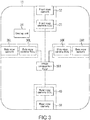
- a plurality of units including a front camera module 71, the communication unit 25, the driving control ECU 51, the steering mechanism 26, the braking device 34, the engine 35, the driving motor 37, the window driving unit 43, and the headlight 44 are connected to each other via a bus 72 for CAN communication.
- a bus 72 for CAN communication the components corresponding to those in Fig. 1 are denoted by the same reference symbols in Fig. 2 , and description thereof will be appropriately omitted.
- the front camera module 71 includes a lens 81, an image sensor 82, the front camera ECU 22, and an MCU (Module Control Unit) 83.
- the lens 81 and the image sensor 82 constitute the front sensing camera 21, and the image sensor 82 includes, for example, a CMOS (Complementary Metal Oxide Semiconductor) image sensor.
- CMOS Complementary Metal Oxide Semiconductor
- the front camera module 71 In the front camera module 71, light from a subject is collected on the imaging surface of the image sensor 82 by the lens 81.
- the image sensor 82 captures a sensing image by photoelectrically converting light that has entered from the lens 81, and supplies it to the front camera ECU 22.
- the front camera ECU 22 performs, for example, gain adjustment, white balance adjustment, HDR (High Dynamic Range) processing, and the like on the sensing image supplied from the image sensor 82, and then performs image recognition on the sensing image.
- gain adjustment for example, gain adjustment, white balance adjustment, HDR (High Dynamic Range) processing, and the like
- HDR High Dynamic Range
- a white line, a curb stone, a pedestrian, a vehicle, a headlight, a brake light, a road sign, a time until a collision with the forward vehicle, and the like are recognized (detected).
- the recognition results of the image recognition are converted into signals in a format for CAN communication by the MCU 83, and output to the bus 72.
- information supplied from the bus 72 is converted into a signal in a format defined for the front camera module 71 by the MCU 83, and supplied to the front camera ECU 22.
- the driving control ECU 51 appropriately controls the steering mechanism 26, the braking device 34, the engine 35, the driving motor 37, the headlight 44, and the like on the basis of the result of image recognition output from the MCU 83 to the bus 72 and information supplied from other units such as the radar 27 and the lidar 28. Accordingly, driving control such as a change in the travelling direction, braking, acceleration, and starting, warning notification control, headlight switching control, and the like are realized. Note that as the switching control of the headlight 44, for example, control of prohibiting high beam, turning off manual/automatic switching control for high beam at the time of drive through, or automatically switching at the time of high beam is performed. Accordingly, driving control such as change of the travelling direction, braking, acceleration, and starting, warning notification control, beam switching control, and the like are realized.
- the locus of the position of the target object may be further recognized by the driving control ECU 51 from the image recognition result at each time obtained by the front camera ECU 22, and such a recognition result may be transmitted to an external server via the communication unit 25.
- learning such as a deep neural network is performed, and a necessary dictionary or the like is generated and transmitted to the vehicle 11.
- the dictionary or the like obtained in this way is received by the communication unit 25, and the received dictionary or the like is used for various predictions and the like in the driving control ECU 51.
- the display unit 24, the window control unit 43, and the like in addition to the steering mechanism 26, the braking device 34, the engine 35, the driving motor 37, and the headlamp are appropriately controlled on the basis of the result of image recognition output from the MCU 83 to the bus 72, information supplied from other units such as the radar 27 and the lidar 28, and the sensing result from the in-vehicle sensor 42. That is, in the drive-through area, the state of the vehicle 11, which includes operations (such as presentation and opening/closing of the window) in addition to the above-mentioned driving (travelling), is controlled.
- control that can be realized from only the result of image recognition on the sensing image may be performed not by the driving control ECU 51 but by the front camera ECU 22.
- the front camera ECU 22 may control the headlight 44 on the basis of the presence or absence of headlight of the oncoming vehicle, which is obtained by the image recognition on the sensing image.
- the front camera ECU 22 generates a control signal that instructs switching between a low beam and a high beam, or the like, and supplies the control signal to the headlight 44 via the MCU 83 and the bus 72, thereby controlling the beam switching by the headlight 44.
- the front camera ECU 22 may generate a warning notice of a collision against an object and a warning notice of departure from the travelling lane (lane) on the basis of the result of recognizing a white line, a curb stone, a pedestrian, and the like, which is obtained by the image recognition on the sensing image, and output it to the bus 72 via the MCU 83, thereby controlling the warning notice.
- the warning notice output from the front camera ECU 22 is supplied to, for example, the display unit 24 or a speaker (not shown). Accordingly, it is possible to display a warning on the display unit 24 or output a warning message through the speaker.
- the around view monitor function is realized.
- the front image, the rear image, and the side image obtained by the respective units are supplied, via a cable different from the bus for CAN communication, to an image composition ECU 101 provided in the integrated ECU 31, and a composite image is generated from the images.
- the components corresponding to those in Fig. 1 are denoted by the same reference symbols in Fig. 3 , and description thereof will be appropriately omitted.
- a side view camera 29L disposed on the left side of the vehicle 11 and a side view camera 29R disposed on the right side of the vehicle 11 are provided.
- a side view camera ECU 30L disposed on the left side of the vehicle 11 and a side view camera ECU 30R disposed on the right side of the vehicle 11 are provided.
- the front image obtained by the front view camera 32 is supplied from the front view camera ECU 33 and the rear image obtained by the rear view camera 39 is supplied from the rear view camera ECU 40.
- the side image obtained by the side view camera 29L (hereinafter, particularly referred to also as the left side image) is supplied from the side view camera ECU 30L and the side image obtained by the side view camera 29R (hereinafter, particularly referred to also as the right side image) is supplied from the side view camera ECU 30R.
- the image composition ECU 101 generates, on the basis of the supplied images, a composite image in which the front image, the rear image, the left side image, and the right side image are arranged in corresponding areas, and supplies the obtained composite image to the display unit 24 for display.
- the driver is capable of safely and easily parking the vehicle 11 by driving the vehicle 11 while watching the composite image displayed in this way.
- the integrated ECU 31 may control the driving of the vehicle 11 on the basis of the composite image, and park the vehicle 11.
- the driving control ECU 51 does not necessarily need to control the plurality of different functions.
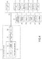
- a control unit may be provided for control content, i.e., each function. Note that the components corresponding to those in Fig. 2 are denoted by the same reference symbols in Fig. 4 , and description thereof will be appropriately omitted.
- a plurality of units including the front camera module 71, the communication unit 25, the steering mechanism 26, the braking device 34, the engine 35, the driving motor 37, the window control unit 43, the headlight 44, a beam control unit 111, a warning notice control unit 112, a steering control unit 113, a break control unit 114, an accelerator control unit 115, an a state control unit 116 are connected.
- control performed by the driving control ECU 51 in the example shown in Fig. 2 is shared and performed by the beam control unit 111, the warning notice control unit 112, the steering control unit 113, the break control unit 114, the accelerator control unit 115, and the state control unit 116.
- the beam control unit 111 performs control of switching a low beam and a high beam by controlling the headlight 44 on the basis of the result of image recognition, which is obtained by the front camera ECU 22.
- the warning notice control unit 112 controls the warning notice such as displaying of various warnings on the display unit 24 and outputting a warning message by the speaker (not shown), on the basis of the result of image recognition, which is obtained by the front camera ECU 22.
- the steering control unit 113 controls the travelling direction of the vehicle 11 by controlling the steering mechanism 26 on the basis of the result of image recognition, which is obtained by the front camera ECU 22, the measurement results from the radar 27 and the lidar 28, and the like.
- the break control unit 114 controls the stop and deceleration of the vehicle 11 by controlling the braking device 34 on the basis of the result of image recognition, which is obtained by the front camera ECU 22, the measurement results from the radar 27 and the lidar 28, and the like.
- the accelerator control unit 115 controls starting and acceleration of the vehicle 11 by controlling the engine 35 and the driving motor 37 on the basis of the result of image recognition, which is obtained by the front camera ECU 22, the measurement results from the radar 27 and the lidar 28, and the like.
- the state control unit 116 controls the display unit 24, the window control unit 43, and the like in addition to the steering mechanism 26, the braking device 34, the engine 35, the driving motor 37, and the headlight 44 described above are appropriately controlled on the basis of the result of image recognition output from the MCU 83 to the bus 72, information supplied from other units such as the radar 27 and the lidar 28, and the sensing result from the in-vehicle sensor 42. That is, in the drive-through area, the state of the vehicle 11, which includes operations (such as presentation and opening/closing of the window) in addition to the above-mentioned driving (travelling), is controlled.
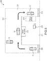
- Fig. 5 is a diagram showing a configuration example of a drive-through area drive control system to which the present technology is applied.
- a drive-through area drive control system 201 includes the vehicle 11 and a store 211 provided with a drive-through facility.
- the store 211 includes also a parking lot 212 for the vehicle 11 that does not receive the drive-through service, at the back of the drive-through facility.
- a drive-through area 221 that is a path through which the vehicle 11 travels along an arrow, an order window 222 at which a user places an order, a pick-up window 223 at which the user pays to the store 211 and receives services or products from the store 211, and a terminal 224 for managing accounting of the store 211, and the like are included.
- the drive-through area 221 includes an entrance 231 and an exit 232 leading to a road. For example, in the example in Fig. 5 , an example of the drive-through facility that provides a hamburger will be described.
- the position information from the position information acquisition unit 23 various types of information such as the peripheral vehicle information supplied from the communication unit 25, the measurement results from the radar 27 and the lidar 28, the detection result of the travelling speed from the speed detection unit 41, the detection result from the in-vehicle sensor 42, and the like, and the above-mentioned driving control ECU 51 controls, in the detected drive-through area, the state of the vehicle 11 including driving (travelling) and operations (such as presentation and opening/closing of the window) of the vehicle 11.
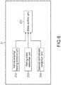
- the driving control ECU 51 includes a state control unit 251, a vehicle entering/leaving detection unit 252, a riding state detection unit 253, and a service completion detection unit 254, as shown in Fig. 6 .
- the state control unit 251 controls, in the drive-through area detected by the vehicle entering/leaving detection unit 252, the state of the vehicle 11 including driving (travelling) and operations (such as presentation and opening/closing of the window) of the vehicle 11, in accordance with the detection results of the vehicle entering/leaving detection unit 252, the riding state detection unit 253, the service completion detection unit 254, and the like.
- the vehicle entering/leaving detection unit 252 detects that the vehicle 11 is in the drive-through area, and supplies the detection result to the state control unit 251. Further, the vehicle entering/leaving detection unit 252 detects that the vehicle 11 that has been in the drive-through area (in a drive-through area mode) leaves from the exit, and supplies the detection result to the state control unit 251.
- the riding state detection unit 253 detects, on the basis of the detection result from the in-vehicle sensor 42, the riding state of the vehicle 11, i.e. , how many passengers are sitting in the front seat or the rear seat of the vehicle 11 and whether he/she is an adult or a child, and supplies the detection result to the state control unit 251.
- the service completion detection unit 254 detects the completion of services (ordering, providing, and payment) on the basis of the image from the front sensing camera 21, for example. Further, for example, a service completion signal is transmitted from the terminal 224 to the vehicle 11 when a clerk presses a button or the like, which indicates the completion of the services, of the terminal 224 in the store 211, and the service completion detection unit 254 receives it to detect the completion of the services.
- the vehicle entering/leaving detection unit 252 determines whether or not it is in the drive-through area, at the entrance 231 of the drive-through area 221. For this determination, for example, the result of image recognition performed on a signboard representing "Drive-through IN, Entrance" or the like from the front camera ECU 22, or the position information from the position information acquisition unit 23 using map information is used, as an example of control performed by the vehicle 11.
- a sensor or the like for recognizing the entrance may be installed at the entrance 231.
- this also applies to the exit 232 of the drive-through area 221. That is, at the exit 232 of the drive-through area 221, for detection of leaving the drive-through area 221, for example, the result of image recognition performed on a signboard representing "Drive-through OUT, Exit" or the like from the front camera ECU 22, or the position information from the position information acquisition unit 23 using map information is used, as an example of control performed by the vehicle 11.
- a sensor or the like for recognizing the exit may be installed at the exit 232.
- the state control unit 251 causes the display unit 24 to display a screen for prompting setting of the drive-through area mode.
- OK (not shown) by the user, the mode of the vehicle 11 is set to a drive mode. Note that in the case where it is determined to be in the drive-through area, the mode may be immediately set to the drive-through area mode without any suggestion.
- automatic driving (guidance for the vehicle 11 on the basis of the facility of the drive-through area 221) is performed.
- the state control unit 251 controls the steering mechanism 26, the braking device 34, the engine 35, the driving motor 37, and the like to cause the vehicle 11 to start moving to the order window 222.
- the riding state detection unit 253 detects, on the basis of the detection result from the in-vehicle sensor 42, the riding state of the vehicle 11, e.g., how many passengers are sitting in the front seat or the rear seat of the vehicle 11 and whether he/she is an adult or a child. Note that in the case where a child seat has been detected, it can be determined that, for example, a child is riding or an adult is not on the place.
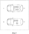
- the state control unit 251 determines a stop position when ordering corresponding to the riding state of the vehicle 11 from the riding state detection unit 253. For example, as shown in Part A of Fig. 7 , in the case where a father (adult) is sitting on the driver's seat and a mother (adult) and a child are sitting on the rear seat, the state control unit 251 determines, to the optimal position where the mother sitting on the rear seat places an order, the stop position of the vehicle 11 when ordering at the order window 222. For example, as shown in Part B of Fig.
- the state control unit 251 determines, to the optimal position where the father on the driver's seat places an order, the stop position of the vehicle 11 when ordering at the order window 222.
- the stop position when ordering at the order window 222 may be preferentially determined to the position of the driver's seat, and a stop position when providing at the pick-up window 223 may be preferentially determined to the position of the rear seat.
- the stop position when ordering may be set to the position of the driver's seat by default, and other setting may be made in the case where there is another passenger. Further, it may be suggested to the user that other setting can be made, only in the case where there is another passenger.
- the stop position determined by the state control unit 251 may be presented to the display unit 24, and a desired position may be selected. Further, each stop position may be set by the user in advance.
- the vehicle 11 is controlled to decelerate from the position (that can be set to, for example, three m) before the stop position when ordering.
- the state control unit 251 stands by until the position of the vehicle 11 reaches the determined stop position when ordering, and controls, in the case where it is determined that it has reached the stop position, the steering mechanism 26, the braking device 34, the engine 35, the driving motor 37, and the like to stop the vehicle 11.
- the state control unit 251 stops the vehicle 11 at the stop position when ordering, and then, controls the window driving unit 43 to automatically open the window so that the user is capable of immediately placing an order.
- the opening/closing of the window is not performed.
- the window is half-opened, control of completely opening it is performed.
- the control of opening the window may be performed corresponding to the weather, e.g., the window is not opened in the case where the air condition is turned ON or it is rainy.
- weather information e.g., being rainy because the wiper is moving
- the front sensing camera 21 may be used for detecting raindrops of the windshield.
- a rain sensor may be used.
- map information or security information metadata acquired from the position information acquisition unit 23 it is also possible to perform control so that the window is not opened at places where security is poor. Note that although the control of opening the window is performed after stopping in the above description, it may be performed before the stopping.
- the service completion detection unit 254 may detect the completion of services (such as ordering) on the basis of the image from the front sensing camera 21, for example. Note that the detection of completion may be performed on the basis of not the image but voice recognition. Further, for example, a clerk presses a button or the like, which indicates the completion of services, of a GUI of the terminal 224 in the store 211, and thus, an order completion signal is transmitted from the terminal 224 to the vehicle 11. In response thereto, the order completion signal received by the communication unit 25 may be supplied to the state control unit 251, and the vehicle 11 may start moving to the next place. Note that the same applies to the pick-up window 223. For example, in the case of the pick-up window 223, a providing completion button, a payment completion button, and the like are provided in the GUI or the like of the terminal 224.
- the state control unit 251 controls the window driving unit 43 to close the window, and controls the steering mechanism 26, the braking device 34, the engine 35, the driving motor 37, and the like to cause the vehicle 11 to start moving to the pick-up window 223.
- a payment window may be separately provided.
- the state of the vehicle 11 also at the payment window is controlled similarly to the order window 222 and the pick-up window 223.
- the vehicle 11 is causes to stop or start moving at at least one window, corresponding to the configuration of the window. Further, also the opening/closing of the window is controlled.
- the drive-through facility that provides a hamburger has been described as an example, the drive-through facility does not necessarily need to provide food, and may be one that provides various goods and services such as medicine, cleaning, car washing, and an ATM.
- Fig. 8 is a block diagram showing a configuration example of the terminal 224.
- a CPU Central Processing Unit
- ROM Read Only Memory
- RAM Random Access Memory
- an input/output interface 305 is further connected.
- an input unit 306 an output unit 307, a storage unit 308, a communication unit 309, and a drive 310 are connected.
- the input unit 306 includes a keyboard, a mouse, a microphone, or the like.
- the output unit 307 includes a display, a speaker, or the like.
- the storage unit 308 includes a hard disk, a non-volatile memory, or the like.
- the communication unit 309 includes a network interface or the like, and communicates with the communication unit 25 of the vehicle 11 or the like.
- the drive 310 drives a removable medium 311 such as a magnetic disk, an optical disk, a magneto-optical disk, and a semiconductor memory.
- the program can be installed in the storage unit 308 via the input/output interface 305 by loading the removable medium 311 to the drive 310. Further, the program can be received by the communication unit 309 via a wired or wireless transmission medium and installed in the storage unit 308. In addition, the program can be installed in advance in the ROM 302 or the storage unit 308.
- Step S11 in Fig. 9 the vehicle entering/leaving detection unit 252 stands by until it is determined to be in a drive-through area.
- a signboard representing "Drive-through IN” or the like at the entrance 231 of the drive-through area 221, or a sensor or the like for recognizing an entrance is installed at the entrance 231.
- the result of image recognition performed on a signboard representing "Drive-through IN" or the like from the front camera ECU 22, or the position information from the position information acquisition unit 23 using map information is used.
- Step S12 the processing proceeds to Step S12. That is, since being in the drive-through area is detected in Step S11, thereafter, the state of the vehicle 11 including driving (travelling) and operations (such as presentation and opening/closing of the window) of the vehicle 11 is controlled in the detected drive-through area.
- the processing of Step S12 and subsequent Steps correspond to the processing of controlling the state of the vehicle 12.
- Step S12 the state control unit 251 urges setting of the drive-through area mode. That is, the state control unit 251 causes the display unit 24 to display a screen urging the setting of the drive-through area mode. Watching the screen displayed on the display unit 24, the user operates that it is OK by a touch panel (not shown) or voice recognition, for example. Note that the processing of Step S12 may be omitted.
- Step S13 the state control unit 251 sets the mode of the vehicle 11 to the drive-through area mode.
- Step S14 the state control unit 251 controls the steering mechanism 26, the braking device 34, the engine 35, the driving motor 37, and the like to cause the vehicle 11 to start moving to the order window 222. Note that in the drive-through area, the maximum speed/moving speed is set to low.
- Step S15 the riding state detection unit 253 detects, on the basis of the detection result from the in-vehicle sensor 42, the riding state of the vehicle 11, e.g., how many passengers are sitting in the front seat or the rear seat of the vehicle 11 and whether he/she is an adult or a child. Then, in Step S16, as described above with reference to Fig. 7 , the riding state detection unit 253 determines the stop position when ordering, corresponding to the riding state of the vehicle 11 from the riding state detection unit 253. Note that the stop position when ordering may be preferentially determined to the position of the driver's seat, and the stop position when providing (delivering) may be preferentially determined to the position of the rear seat.
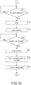
- the state control unit 251 stands by until it is determined in Step S17 in Fig. 10 that the position of the vehicle 11 reaches the determined stop position when ordering. In the case where it is determined in Step S17 that it reaches the stop position, the processing proceeds to Step S18. In Step S18, the state control unit 251 controls the steering mechanism 26, the braking device 34, the engine 35, the driving motor 37, and the like to stop the vehicle 11.
- Step S19 the state control unit 251 controls the window driving unit 43 to open the window, corresponding to the stop position when ordering determined in Step S16 so that the user is capable of immediately placing an order. Then, the user places an order.
- Step S20 the state control unit 251 stands by until it is determined that the order has been completed. For example, the completion of the order is detected on the basis of the image from the front sensing camera 21. In response thereto, in the case where it is determined in Step S20 that the order is completed, the processing proceeds to Step S21.
- the state control unit 251 controls, in Step S21, the window driving unit 43 to close window, and controls, in Step S22, the steering mechanism 26, the braking device 34, the engine 35, the driving motor 37, and the like to cause the vehicle 11 to start moving to the pick-up window 223.
- the closing is not indispensable and does not necessarily need to be performed.
- Step S23 the riding state of the vehicle 11 is detected on the basis of the detection result from the riding state detection unit 253.
- Step S24 in Fig. 11 the state control unit 251 determines the stop position when providing, corresponding to the riding state of the vehicle 11 as described above with reference to Fig. 7 .
- Step S25 the state control unit 251 controls the steering mechanism 26, the braking device 34, the engine 35, the driving motor 37, and the like to stop the vehicle 11.
- Step S26 the state control unit 251 controls the window driving unit 43 to open the window so that the user is capable of immediately placing an order. Then, the user receives the provision (receives the products) and makes the payment. Note that in addition to the above-mentioned determination method, further, at the time of payment, whether or not the payment has been completed by ETC payment can be determined. Note that although the ETC payment is performed with a special device installed in a credit card or a car in Japan, the payment may be performed simply by reading a number with a camera or attaching a dedicated tag on the windshield as in foreign countries.
- Step S27 the driving control ECU 51 stands by until it is determined that the provision and payment have been completed. For example, the completion of the payment is detected on the basis of the image from the front sensing camera 21. In response thereto, in the case where it is determined in Step S27 that the payment has been completed, the processing proceeds to Step S28.
- the state control unit 251 controls, in Step S28, the window driving unit 43 to close the window, and controls, in Step S29, the steering mechanism 26, the braking device 34, the engine 35, the driving motor 37, and the like to cause the vehicle 11 to start moving to the pick-up window 223. Note that in the case where the window has been originally opened before opening the window, it does not need to close the window. Further, in the case where the window has been originally half-opened, the window is closed by the amount corresponding thereto.
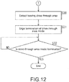
- the state control unit 251 detects, in Step S30 in Fig. 12 , the exit 232 at the exit 232 in the drive-through area 221, determines to leave the drive-through area 221, and causes, in Step S31, the display unit 24 to display the screen urging termination of the drive-through area mode. Note that at this time, it is effective to suggest, by a screen or voice, to the user that he/she should wipe the hands, because there is a possibility that he/she has eaten a hamburger or the like in the drive-through area.
- Step S32 the state control unit 251 stands by until the drive-through area mode is terminated. Watching the screen displayed on the display unit 24, the user operates OK (not shown). In response thereto, in the case where it is determined in Step S32 that the drive-through area mode is to be terminated, the drive-through area mode is terminated (setting is cancelled), and the state control processing is finished. Note that also the setting cancellation of the drive-through area mode may be performed without any suggestion similarly to the case of the setting.
- being in a drive-through area is detected, and the state of the vehicle 11 including driving (travelling) and operations (such as presentation and opening/closing of the window) of the vehicle 11 is controlled in the detected drive-through area. Accordingly, it is possible to perform driving assistance in the drive-through area.
- the window may be opened as long as it is after the timing when being in the drive-through area has been detected, the window may be closed after the final service at the window is finished even in the case where the opening/closing of the window is not performed at each window, or the window may be closed before leaving the drive-through area.
- the opening/closing timing in what situation the window is not to be opened, and the like may be set in advance. Further, it does not necessarily need to perform operation control regarding the opening/closing of the window, and it may be suggested to the user that he/she should opening/close the window.
- the vehicle 11 starts moving after the service has been completed has been described in this example, it may be when the user is about to step on the accelerator. Further, in the case where an object is dropped from a window or the like, since it can be imaged by the side view camera 29 or the like and detected, irregular processing, e.g., stopping of automatic driving, may be performed.
- the store 211 may be controlled as a whole.
- the terminal 224 on the store side functions as not only an accountant apparatus but also a vehicle state control apparatus, and performs a cloud-like operation.
- the terminal 224 receives the result sensed by the vehicle, and transmits a control signal to the vehicle. In this way, the above-mentioned control on the vehicle is realized by the terminal 224 on the store side.
- an infrared sensor (trip-wire sensor) is prepared at this position.
- V2I Vehicle-to-Infrastracture
- stop control may be performed by the vehicle 11.
- the series of processes described above can be performed by hardware or software.
- programs that constitute the software are installed in a computer.
- Examples of the computer include a computer incorporated in dedicated hardware, a general-purpose personal computer capable of executing various functions by installing various programs, as described above with reference to the terminal 224 Fig. 5 , and the like.
- program executed by the computer may be a program in which processing is chronologically performed in the order described herein or may be a program in which processing is performed in parallel or at a necessary timing, for example, upon calling.
- the steps describing the program to be recorded in a recording medium include processing chronologically performed in the described order. However, the processing does not necessarily need to be chronologically performed. The steps also include processing executed in parallel or individually.
- system represents the entire apparatus including a plurality of devices (apparatuses).
- the present invention may take a cloud computing configuration in which a single function is shared and commonly processed by a plurality of apparatuses over a network.
Landscapes
- Engineering & Computer Science (AREA)
- Physics & Mathematics (AREA)
- General Physics & Mathematics (AREA)
- Business, Economics & Management (AREA)
- Finance (AREA)
- Accounting & Taxation (AREA)
- Remote Sensing (AREA)
- Radar, Positioning & Navigation (AREA)
- Automation & Control Theory (AREA)
- Theoretical Computer Science (AREA)
- Aviation & Aerospace Engineering (AREA)
- Multimedia (AREA)
- Development Economics (AREA)
- Economics (AREA)
- Marketing (AREA)
- Strategic Management (AREA)
- General Business, Economics & Management (AREA)
- Transportation (AREA)
- Mechanical Engineering (AREA)
- Electromagnetism (AREA)
- Computer Vision & Pattern Recognition (AREA)
- Optics & Photonics (AREA)
- Chemical & Material Sciences (AREA)
- Combustion & Propulsion (AREA)
- Traffic Control Systems (AREA)
- Control Of Driving Devices And Active Controlling Of Vehicle (AREA)
- Health & Medical Sciences (AREA)
- Artificial Intelligence (AREA)
- Evolutionary Computation (AREA)
- Game Theory and Decision Science (AREA)
- Medical Informatics (AREA)
Claims (11)
- Fahrzeugstatussteuervorrichtung, die Folgendes umfasst:eine Fahrzeugeinfahrts-/-ausfahrtsdetektionseinheit (252), die dazu ausgelegt ist, die Anwesenheit in einem Durchfahrtsbereich (221) zu detektieren; undeine Steuereinheit (251), die dazu ausgelegt ist, einen Status eines Fahrzeugs (11) im Durchfahrtsbereich (221),der von der Fahrzeugeinfahrts-/- ausfahrtsdetektionseinheit (252) detektiert wird, zu steuern, undeine Fahrstatusdetektionseinheit (253), die dazu ausgelegt ist, einen Fahrstatus des Fahrzeugs (11) zu detektieren, wobei der Fahrstatus Informationen darüber umfasst, wie viele Passagiere auf dem Vordersitz oderdem Rücksitz des Fahrzeugs (11) sitzen und ob der Passagier ein Erwachsener oder ein Kind ist, wobei die Steuereinheit (251) dazu ausgelegt ist, den Bewegungsstatus des Fahrzeugs (11) entsprechend dem Fahrstatus zu steuern und das Fahrzeug (11) an mindestens einem von einem Bestellfenster (222), einem Abholfenster (223) oder einem Bezahlfenster insbesondere in einer Position, die dem Fahrstatus des Fahrzeugs (11) an dem mindestens einen Fenster entspricht, als den Bewegungsstatus des Fahrzeugs (11) anzuhalten.
- Fahrzeugstatussteuervorrichtung nach einem der vorhergehenden Ansprüche, wobei
die Steuereinheit (251), wenn ein Service an dem mindestens einen Fenster beendet ist, dazu ausgelegt ist, das Bewegen des Fahrzeugs (11), wobei der Bewegungsstatus des Fahrzeugs (11) angehalten ist, zu steuern. - Fahrzeugstatussteuervorrichtung nach Anspruch 2, die ferner eine Serviceabschlussdetektionseinheit (254) umfasst, die dazu ausgelegt ist, den Abschluss eines Service zu detektieren, wobei
die Steuereinheit (251) dazu ausgelegt ist, das Bewegen des Fahrzeugs (11), wobei der Bewegungsstatus des Fahrzeugs (11) angehalten ist, gemäß einem Detektionsergebnis des Abschlusses des Service durch die Serviceabschlussdetektionseinheit (254) zu steuern. - Fahrzeugstatussteuervorrichtung nach Anspruch 3, wobei
die Steuereinheit (251), wenn der Abschluss des Service, insbesondere eines Bezahlungsservice, von der Serviceabschlussdetektionseinheit (254) detektiert wird, dazu ausgelegt ist zu bewirken, dass sich das Fahrzeug (11), wobei der Bewegungsstatus des Fahrzeugs (11) angehalten ist, in Bewegung setzt. - Fahrzeugstatussteuervorrichtung nach einem der vorhergehenden Ansprüche, wobei
die Steuereinheit (251), wenn die Anwesenheit im Durchfahrtsbereich (221) von der Fahrzeugeinfahrts-/- ausfahrtsdetektionseinheit (252) detektiert wird oder das Fahrzeug (11) an dem mindestens einen Fenster angehalten wird, dazu ausgelegt ist, das Öffnen/Schließen eines Fensters des Fahrzeugs (11) als den Status des Fahrzeugs (11) zu steuern. - Fahrzeugstatussteuervorrichtung nach Anspruch 5, wobei
die Steuereinheit (251) dazu ausgelegt ist, das Öffnen/Schließen des Fensters des Fahrzeugs (11) entsprechend dem Wetter zu steuern. - Fahrzeugstatussteuervorrichtung nach Anspruch 5, wobei
die Steuereinheit (251) dazu ausgelegt ist, das Öffnen/Schließen des Fensters des Fahrzeugs (11) entsprechend einem Sicherheitsstatus zu steuern, insbesondere dazu ausgelegt ist, unter einer Bedingung, dass der Service an dem mindestens einen Fenster beendet ist oder Services an allen Fenstern beendet sind, das geöffnete Fenster des Fahrzeugs (11) zu schließen. - Fahrzeugstatussteuervorrichtung nach einem der vorhergehenden Ansprüche, wobei
die Steuereinheit (251), wenn die Anwesenheit im Durchfahrtsbereich (221) von der Fahrzeugeinfahrts-/- ausfahrtsdetektionseinheit detektiert wird, dazu ausgelegt ist, einen Benutzer über die Präsentation zum Auswählen, ob ein Modus des Fahrzeugs (11) auf einen Durchfahrtsbereichsmodus eingestellt werden soll, bei dem es sich um einen Fahrunterstützungsmodus im Durchfahrtsbereich (221) handelt, zu benachrichtigen. - Fahrzeugstatussteuervorrichtung nach Anspruch 8, wobeidie Fahrzeugeinfahrts-/-ausfahrtsdetektionseinheit (252), wenn der Durchfahrtsbereichsmodus eingestellt ist, dazu ausgelegt ist, das Herausfahren aus dem Durchfahrtsbereich (221) zu detektieren, unddie Steuereinheit (251), wenn das Herausfahren aus dem Durchfahrtsbereich (221) von der Fahrzeugeinfahrts-/- ausfahrtsdetektionseinheit detektiert wird, dazu ausgelegt ist, den Benutzer über die Präsentation dazu, ob der Durchfahrtsbereichsmodus des Fahrzeugs freigegeben werden soll, zu benachrichtigen.
- Fahrzeugstatussteuerverfahren, das Folgendes durch eine Fahrzeugstatussteuervorrichtung umfasst, Detektieren der Anwesenheit in einem Durchfahrtsbereich (221) ;Steuern eines Status eines Fahrzeugs (11) im Durchfahrtsbereich (221);Detektieren eines Fahrstatus des Fahrzeugs (11) durch eine Fahrstatusdetektionseinheit (253) der Fahrzeugstatussteuervorrichtung; wobei der Fahrstatus Informationen darüber umfasst, wie viele Passagiere auf dem Vordersitz oder dem Rücksitz des Fahrzeugs (11) sitzen und ob der Passagier ein Erwachsener oder ein Kind ist;Steuern des Bewegungsstatus des Fahrzeugs (11) entsprechend dem Fahrstatus des Fahrzeugs (11) und Anhalten des Fahrzeugs (11) an mindestens einem von einem Bestellfenster (222), einem Abholfenster (223) oder einem Bezahlfenster insbesondere in einer Position, die dem Fahrstatus des Fahrzeugs (11) an dem mindestens einen Fenster entspricht, als den Bewegungsstatus des Fahrzeugs (11).
- Fahrzeug, das eine Fahrzeugstatussteuervorrichtung nach einem der Ansprüche 1 bis 9 umfasst.
Applications Claiming Priority (2)
| Application Number | Priority Date | Filing Date | Title |
|---|---|---|---|
| JP2016164363 | 2016-08-25 | ||
| PCT/JP2017/029194 WO2018037950A1 (ja) | 2016-08-25 | 2017-08-10 | 車両の状態制御装置および方法、並びに車両 |
Publications (3)
| Publication Number | Publication Date |
|---|---|
| EP3506236A1 EP3506236A1 (de) | 2019-07-03 |
| EP3506236A4 EP3506236A4 (de) | 2019-09-04 |
| EP3506236B1 true EP3506236B1 (de) | 2022-01-12 |
Family
ID=61244919
Family Applications (1)
| Application Number | Title | Priority Date | Filing Date |
|---|---|---|---|
| EP17843433.8A Not-in-force EP3506236B1 (de) | 2016-08-25 | 2017-08-10 | Fahrzeugzustandssteuerungsvorrichtung und -verfahren sowie fahrzeug |
Country Status (5)
| Country | Link |
|---|---|
| US (1) | US11409283B2 (de) |
| EP (1) | EP3506236B1 (de) |
| JP (1) | JP7006601B2 (de) |
| CN (1) | CN109564731B (de) |
| WO (1) | WO2018037950A1 (de) |
Families Citing this family (15)
| Publication number | Priority date | Publication date | Assignee | Title |
|---|---|---|---|---|
| JP6928907B2 (ja) * | 2017-02-23 | 2021-09-01 | パナソニックIpマネジメント株式会社 | 車両制御装置、車両制御方法、プログラム及びそれを記録した記録媒体 |
| FR3072334B1 (fr) * | 2017-10-16 | 2019-11-01 | Innovaction Technologies | Systeme et procede de commande d'un vehicule automobile muni d'au moins une couverture amovible. |
| US11971714B2 (en) * | 2018-02-19 | 2024-04-30 | Martin Tremblay | Systems and methods for autonomous vehicles |
| JP7070047B2 (ja) * | 2018-04-26 | 2022-05-18 | コベルコ建機株式会社 | 旋回式作業機械の旋回制御装置 |
| JP7110935B2 (ja) * | 2018-11-21 | 2022-08-02 | トヨタ自動車株式会社 | 停止位置制御装置、停止位置制御方法、及び停止位置制御用コンピュータプログラム |
| CN110060671A (zh) * | 2019-03-06 | 2019-07-26 | 惠州市德赛西威汽车电子股份有限公司 | 一种基于adas的车窗语音控制方法 |
| JP6962997B2 (ja) * | 2019-12-13 | 2021-11-05 | 本田技研工業株式会社 | 走行支援システムおよびその制御方法 |
| US11851060B2 (en) * | 2020-03-15 | 2023-12-26 | Ron Zass | Controlling vehicles in response to windows |
| KR20220039980A (ko) * | 2020-09-22 | 2022-03-30 | 현대자동차주식회사 | 편의시설 경유 제안 장치 및 이를 포함한 자율 주행 차량 |
| JP7615906B2 (ja) * | 2021-06-14 | 2025-01-17 | トヨタ自動車株式会社 | 洗車装置 |
| US20230041498A1 (en) * | 2021-08-04 | 2023-02-09 | Ford Global Technologies, Llc | Driver Assistance Systems And Methods For Deployment In A Drive-Through Lane |
| KR102569411B1 (ko) * | 2021-09-08 | 2023-08-22 | 주식회사 에이치엘클레무브 | 차량의 자율 주행 제어 장치 및 방법 |
| JP7694525B2 (ja) * | 2022-09-29 | 2025-06-18 | トヨタ自動車株式会社 | 支援装置 |
| JP2024065519A (ja) * | 2022-10-31 | 2024-05-15 | トヨタ自動車株式会社 | 車両 |
| WO2026075667A1 (en) * | 2024-10-04 | 2026-04-09 | Micky's Luck, Llc | Drive-thru golf food, beverage and merchandise system |
Citations (2)
| Publication number | Priority date | Publication date | Assignee | Title |
|---|---|---|---|---|
| WO2015057144A1 (en) * | 2013-10-16 | 2015-04-23 | Scania Cv Ab | Method and system for managing the stopping of a motor vehicle |
| DE102015015283A1 (de) * | 2014-12-05 | 2016-06-09 | Scania Cv Ab | Vorrichtung und Verfahren zum Regeln einer Geschwindigkeit eines Fahrzeugs |
Family Cites Families (24)
| Publication number | Priority date | Publication date | Assignee | Title |
|---|---|---|---|---|
| JPH11296798A (ja) * | 1998-04-07 | 1999-10-29 | Nec Corp | 車両安全通過システム |
| US6748308B2 (en) * | 2001-03-30 | 2004-06-08 | Siemens Vdo Automotive Corporation | Automated closure system and method |
| JP2004168415A (ja) * | 2002-11-21 | 2004-06-17 | Yoshiro Adachi | 携帯情報端末を使ったガソリン等自動車用燃料供給システム |
| JP2004280729A (ja) * | 2003-03-18 | 2004-10-07 | Toyota Infotechnology Center Co Ltd | 自動料金収受システム、プログラム、記録媒体および自動料金収受方法 |
| JP2004355145A (ja) * | 2003-05-27 | 2004-12-16 | Denso Corp | 車両制御装置 |
| JP2006264472A (ja) * | 2005-03-23 | 2006-10-05 | Fujitsu Ten Ltd | 車体装備制御装置および車体装備制御方法 |
| JP2007183824A (ja) | 2006-01-06 | 2007-07-19 | Advanced Telecommunication Research Institute International | 運転支援装置 |
| JP4682880B2 (ja) * | 2006-03-07 | 2011-05-11 | 株式会社デンソー | 駐車補助装置 |
| WO2007113809A2 (en) * | 2006-03-30 | 2007-10-11 | Saban Asher S | Protecting children and passengers with respect to a vehicle |
| JP4894731B2 (ja) * | 2007-11-07 | 2012-03-14 | トヨタ自動車株式会社 | 追従走行制御システム |
| CN101510320A (zh) * | 2008-02-13 | 2009-08-19 | 深圳鼎识科技有限公司 | 车载射频识别电子卡 |
| US8799037B2 (en) * | 2010-10-14 | 2014-08-05 | Palto Alto Research Center Incorporated | Computer-implemented system and method for managing motor vehicle parking reservations |
| KR101305630B1 (ko) * | 2011-09-30 | 2013-09-09 | 현대자동차주식회사 | 주차영역 자동 가변형 주차보조 시스템 및 그 방법 |
| US9381916B1 (en) * | 2012-02-06 | 2016-07-05 | Google Inc. | System and method for predicting behaviors of detected objects through environment representation |
| CN103761864A (zh) * | 2012-06-25 | 2014-04-30 | 周忠新 | 城市机动车违章及时取证系统 |
| JP5849076B2 (ja) * | 2013-09-20 | 2016-01-27 | 株式会社大垣共立銀行 | ドライブスルー用金融店舗の車両の誘導方法 |
| CN104952276A (zh) * | 2014-03-31 | 2015-09-30 | 苏州呈烽物联网信息科技有限公司 | 一种基于到具体车位的云加端的停车位预订保留系统 |
| US9507345B2 (en) * | 2014-04-10 | 2016-11-29 | Nissan North America, Inc. | Vehicle control system and method |
| KR101693943B1 (ko) * | 2014-12-09 | 2017-01-09 | 현대자동차주식회사 | 차량용 탑승자 보호 방법 |
| JP6298772B2 (ja) | 2015-01-14 | 2018-03-20 | 日立オートモティブシステムズ株式会社 | 車載用制御装置、自車位置姿勢特定装置、車載用表示装置 |
| CN104992562B (zh) * | 2015-06-15 | 2018-04-17 | 交通运输部科学研究院 | 一种多模式射频标识一体化接入方法 |
| KR101942793B1 (ko) * | 2015-07-03 | 2019-01-28 | 엘지전자 주식회사 | 차량 운전 보조장치 및 이를 포함하는 차량 |
| JP2017097695A (ja) * | 2015-11-26 | 2017-06-01 | 三菱電機株式会社 | 車両停車誘導システムおよび車両停車誘導方法 |
| CN205440122U (zh) * | 2016-04-11 | 2016-08-10 | 山东理工大学 | 一种提高车门开启安全性的装置 |
-
2017
- 2017-08-10 EP EP17843433.8A patent/EP3506236B1/de not_active Not-in-force
- 2017-08-10 JP JP2018535604A patent/JP7006601B2/ja not_active Expired - Fee Related
- 2017-08-10 WO PCT/JP2017/029194 patent/WO2018037950A1/ja not_active Ceased
- 2017-08-10 CN CN201780050420.2A patent/CN109564731B/zh not_active Expired - Fee Related
- 2017-08-10 US US16/325,592 patent/US11409283B2/en active Active
Patent Citations (2)
| Publication number | Priority date | Publication date | Assignee | Title |
|---|---|---|---|---|
| WO2015057144A1 (en) * | 2013-10-16 | 2015-04-23 | Scania Cv Ab | Method and system for managing the stopping of a motor vehicle |
| DE102015015283A1 (de) * | 2014-12-05 | 2016-06-09 | Scania Cv Ab | Vorrichtung und Verfahren zum Regeln einer Geschwindigkeit eines Fahrzeugs |
Also Published As
| Publication number | Publication date |
|---|---|
| CN109564731A (zh) | 2019-04-02 |
| EP3506236A1 (de) | 2019-07-03 |
| US20190179315A1 (en) | 2019-06-13 |
| JPWO2018037950A1 (ja) | 2019-06-20 |
| JP7006601B2 (ja) | 2022-01-24 |
| WO2018037950A1 (ja) | 2018-03-01 |
| EP3506236A4 (de) | 2019-09-04 |
| CN109564731B (zh) | 2022-07-08 |
| US11409283B2 (en) | 2022-08-09 |
Similar Documents
| Publication | Publication Date | Title |
|---|---|---|
| EP3506236B1 (de) | Fahrzeugzustandssteuerungsvorrichtung und -verfahren sowie fahrzeug | |
| EP3517384B1 (de) | Fahrzeugsteuerungsvorrichtung, fahrzeugsteuerungsverfahren und beweglicher körper | |
| US10884412B2 (en) | Autonomous vehicle and method of controlling the same | |
| EP3514780A1 (de) | Bilderfassungsvorrichtung, signalverarbeitungsvorrichtung und fahrzeugsteuerungssystem | |
| CN109564734B (zh) | 驾驶辅助装置、驾驶辅助方法、移动体和程序 | |
| US20200086889A1 (en) | Vehicle control apparatus, vehicle control method, and movable object | |
| JP6922919B2 (ja) | 運転支援装置および方法、移動体、並びにプログラム | |
| WO2007105792A1 (ja) | 監視装置および監視方法、制御装置および制御方法、並びにプログラム | |
| US20140078291A1 (en) | Driver Assisting System and Method for a Motor Vehicle | |
| CN207241570U (zh) | 具有三路录像功能的智能后视镜及汽车 | |
| US20260097655A1 (en) | Vehicle function information providing system and vehicle function information providing method | |
| CN207078065U (zh) | 一种汽车停车开门预警系统 | |
| CA3037117C (en) | Vehicle control apparatus, vehicle control method, and movable object | |
| US12570305B2 (en) | Driving information display apparatus and method | |
| CN119636580A (zh) | 后视镜防刮擦控制方法、装置、设备及存储介质 | |
| KR20250100372A (ko) | 운전자 행동 패턴에 기초한 차량의 운전자 프로필 자동 설정 방법 및 장치 | |
| KR20230168060A (ko) | 차량의 안전 하차를 지원하는 방법 및 장치 | |
| JP2009241651A (ja) | 車両用降車補助装置及び降車意思判定装置並びに方法 |
Legal Events
| Date | Code | Title | Description |
|---|---|---|---|
| STAA | Information on the status of an ep patent application or granted ep patent |
Free format text: STATUS: THE INTERNATIONAL PUBLICATION HAS BEEN MADE |
|
| PUAI | Public reference made under article 153(3) epc to a published international application that has entered the european phase |
Free format text: ORIGINAL CODE: 0009012 |
|
| STAA | Information on the status of an ep patent application or granted ep patent |
Free format text: STATUS: REQUEST FOR EXAMINATION WAS MADE |
|
| 17P | Request for examination filed |
Effective date: 20190218 |
|
| AK | Designated contracting states |
Kind code of ref document: A1 Designated state(s): AL AT BE BG CH CY CZ DE DK EE ES FI FR GB GR HR HU IE IS IT LI LT LU LV MC MK MT NL NO PL PT RO RS SE SI SK SM TR |
|
| AX | Request for extension of the european patent |
Extension state: BA ME |
|
| A4 | Supplementary search report drawn up and despatched |
Effective date: 20190802 |
|
| RIC1 | Information provided on ipc code assigned before grant |
Ipc: G08G 1/16 20060101ALI20190729BHEP Ipc: B60W 30/06 20060101ALI20190729BHEP Ipc: G08G 1/09 20060101AFI20190729BHEP Ipc: G06Q 30/06 20120101ALI20190729BHEP |
|
| DAV | Request for validation of the european patent (deleted) | ||
| DAX | Request for extension of the european patent (deleted) | ||
| STAA | Information on the status of an ep patent application or granted ep patent |
Free format text: STATUS: EXAMINATION IS IN PROGRESS |
|
| 17Q | First examination report despatched |
Effective date: 20200619 |
|
| RAP3 | Party data changed (applicant data changed or rights of an application transferred) |
Owner name: SONY GROUP CORPORATION |
|
| GRAP | Despatch of communication of intention to grant a patent |
Free format text: ORIGINAL CODE: EPIDOSNIGR1 |
|
| STAA | Information on the status of an ep patent application or granted ep patent |
Free format text: STATUS: GRANT OF PATENT IS INTENDED |
|
| INTG | Intention to grant announced |
Effective date: 20210802 |
|
| GRAS | Grant fee paid |
Free format text: ORIGINAL CODE: EPIDOSNIGR3 |
|
| GRAA | (expected) grant |
Free format text: ORIGINAL CODE: 0009210 |
|
| STAA | Information on the status of an ep patent application or granted ep patent |
Free format text: STATUS: THE PATENT HAS BEEN GRANTED |
|
| AK | Designated contracting states |
Kind code of ref document: B1 Designated state(s): AL AT BE BG CH CY CZ DE DK EE ES FI FR GB GR HR HU IE IS IT LI LT LU LV MC MK MT NL NO PL PT RO RS SE SI SK SM TR |
|
| REG | Reference to a national code |
Ref country code: GB Ref legal event code: FG4D |
|
| REG | Reference to a national code |
Ref country code: CH Ref legal event code: EP |
|
| REG | Reference to a national code |
Ref country code: DE Ref legal event code: R096 Ref document number: 602017052342 Country of ref document: DE |
|
| REG | Reference to a national code |
Ref country code: IE Ref legal event code: FG4D |
|
| REG | Reference to a national code |
Ref country code: AT Ref legal event code: REF Ref document number: 1462889 Country of ref document: AT Kind code of ref document: T Effective date: 20220215 |
|
| REG | Reference to a national code |
Ref country code: NL Ref legal event code: FP |
|
| REG | Reference to a national code |
Ref country code: LT Ref legal event code: MG9D |
|
| REG | Reference to a national code |
Ref country code: AT Ref legal event code: MK05 Ref document number: 1462889 Country of ref document: AT Kind code of ref document: T Effective date: 20220112 |
|
| PG25 | Lapsed in a contracting state [announced via postgrant information from national office to epo] |
Ref country code: SE Free format text: LAPSE BECAUSE OF FAILURE TO SUBMIT A TRANSLATION OF THE DESCRIPTION OR TO PAY THE FEE WITHIN THE PRESCRIBED TIME-LIMIT Effective date: 20220112 Ref country code: RS Free format text: LAPSE BECAUSE OF FAILURE TO SUBMIT A TRANSLATION OF THE DESCRIPTION OR TO PAY THE FEE WITHIN THE PRESCRIBED TIME-LIMIT Effective date: 20220112 Ref country code: PT Free format text: LAPSE BECAUSE OF FAILURE TO SUBMIT A TRANSLATION OF THE DESCRIPTION OR TO PAY THE FEE WITHIN THE PRESCRIBED TIME-LIMIT Effective date: 20220512 Ref country code: NO Free format text: LAPSE BECAUSE OF FAILURE TO SUBMIT A TRANSLATION OF THE DESCRIPTION OR TO PAY THE FEE WITHIN THE PRESCRIBED TIME-LIMIT Effective date: 20220412 Ref country code: LT Free format text: LAPSE BECAUSE OF FAILURE TO SUBMIT A TRANSLATION OF THE DESCRIPTION OR TO PAY THE FEE WITHIN THE PRESCRIBED TIME-LIMIT Effective date: 20220112 Ref country code: HR Free format text: LAPSE BECAUSE OF FAILURE TO SUBMIT A TRANSLATION OF THE DESCRIPTION OR TO PAY THE FEE WITHIN THE PRESCRIBED TIME-LIMIT Effective date: 20220112 Ref country code: ES Free format text: LAPSE BECAUSE OF FAILURE TO SUBMIT A TRANSLATION OF THE DESCRIPTION OR TO PAY THE FEE WITHIN THE PRESCRIBED TIME-LIMIT Effective date: 20220112 Ref country code: BG Free format text: LAPSE BECAUSE OF FAILURE TO SUBMIT A TRANSLATION OF THE DESCRIPTION OR TO PAY THE FEE WITHIN THE PRESCRIBED TIME-LIMIT Effective date: 20220412 |
|
| PG25 | Lapsed in a contracting state [announced via postgrant information from national office to epo] |
Ref country code: PL Free format text: LAPSE BECAUSE OF FAILURE TO SUBMIT A TRANSLATION OF THE DESCRIPTION OR TO PAY THE FEE WITHIN THE PRESCRIBED TIME-LIMIT Effective date: 20220112 Ref country code: LV Free format text: LAPSE BECAUSE OF FAILURE TO SUBMIT A TRANSLATION OF THE DESCRIPTION OR TO PAY THE FEE WITHIN THE PRESCRIBED TIME-LIMIT Effective date: 20220112 Ref country code: GR Free format text: LAPSE BECAUSE OF FAILURE TO SUBMIT A TRANSLATION OF THE DESCRIPTION OR TO PAY THE FEE WITHIN THE PRESCRIBED TIME-LIMIT Effective date: 20220413 Ref country code: FI Free format text: LAPSE BECAUSE OF FAILURE TO SUBMIT A TRANSLATION OF THE DESCRIPTION OR TO PAY THE FEE WITHIN THE PRESCRIBED TIME-LIMIT Effective date: 20220112 Ref country code: AT Free format text: LAPSE BECAUSE OF FAILURE TO SUBMIT A TRANSLATION OF THE DESCRIPTION OR TO PAY THE FEE WITHIN THE PRESCRIBED TIME-LIMIT Effective date: 20220112 |
|
| PG25 | Lapsed in a contracting state [announced via postgrant information from national office to epo] |
Ref country code: IS Free format text: LAPSE BECAUSE OF FAILURE TO SUBMIT A TRANSLATION OF THE DESCRIPTION OR TO PAY THE FEE WITHIN THE PRESCRIBED TIME-LIMIT Effective date: 20220512 |
|
| REG | Reference to a national code |
Ref country code: DE Ref legal event code: R097 Ref document number: 602017052342 Country of ref document: DE |
|
| PG25 | Lapsed in a contracting state [announced via postgrant information from national office to epo] |
Ref country code: SM Free format text: LAPSE BECAUSE OF FAILURE TO SUBMIT A TRANSLATION OF THE DESCRIPTION OR TO PAY THE FEE WITHIN THE PRESCRIBED TIME-LIMIT Effective date: 20220112 Ref country code: SK Free format text: LAPSE BECAUSE OF FAILURE TO SUBMIT A TRANSLATION OF THE DESCRIPTION OR TO PAY THE FEE WITHIN THE PRESCRIBED TIME-LIMIT Effective date: 20220112 Ref country code: RO Free format text: LAPSE BECAUSE OF FAILURE TO SUBMIT A TRANSLATION OF THE DESCRIPTION OR TO PAY THE FEE WITHIN THE PRESCRIBED TIME-LIMIT Effective date: 20220112 Ref country code: EE Free format text: LAPSE BECAUSE OF FAILURE TO SUBMIT A TRANSLATION OF THE DESCRIPTION OR TO PAY THE FEE WITHIN THE PRESCRIBED TIME-LIMIT Effective date: 20220112 Ref country code: DK Free format text: LAPSE BECAUSE OF FAILURE TO SUBMIT A TRANSLATION OF THE DESCRIPTION OR TO PAY THE FEE WITHIN THE PRESCRIBED TIME-LIMIT Effective date: 20220112 Ref country code: CZ Free format text: LAPSE BECAUSE OF FAILURE TO SUBMIT A TRANSLATION OF THE DESCRIPTION OR TO PAY THE FEE WITHIN THE PRESCRIBED TIME-LIMIT Effective date: 20220112 |
|
| PLBE | No opposition filed within time limit |
Free format text: ORIGINAL CODE: 0009261 |
|
| STAA | Information on the status of an ep patent application or granted ep patent |
Free format text: STATUS: NO OPPOSITION FILED WITHIN TIME LIMIT |
|
| PG25 | Lapsed in a contracting state [announced via postgrant information from national office to epo] |
Ref country code: AL Free format text: LAPSE BECAUSE OF FAILURE TO SUBMIT A TRANSLATION OF THE DESCRIPTION OR TO PAY THE FEE WITHIN THE PRESCRIBED TIME-LIMIT Effective date: 20220112 |
|
| 26N | No opposition filed |
Effective date: 20221013 |
|
| PG25 | Lapsed in a contracting state [announced via postgrant information from national office to epo] |
Ref country code: SI Free format text: LAPSE BECAUSE OF FAILURE TO SUBMIT A TRANSLATION OF THE DESCRIPTION OR TO PAY THE FEE WITHIN THE PRESCRIBED TIME-LIMIT Effective date: 20220112 |
|
| REG | Reference to a national code |
Ref country code: DE Ref legal event code: R119 Ref document number: 602017052342 Country of ref document: DE |
|
| PG25 | Lapsed in a contracting state [announced via postgrant information from national office to epo] |
Ref country code: MC Free format text: LAPSE BECAUSE OF FAILURE TO SUBMIT A TRANSLATION OF THE DESCRIPTION OR TO PAY THE FEE WITHIN THE PRESCRIBED TIME-LIMIT Effective date: 20220112 |
|
| REG | Reference to a national code |
Ref country code: CH Ref legal event code: PL |
|
| REG | Reference to a national code |
Ref country code: NL Ref legal event code: MM Effective date: 20220901 |
|
| GBPC | Gb: european patent ceased through non-payment of renewal fee |
Effective date: 20220810 |
|
| PG25 | Lapsed in a contracting state [announced via postgrant information from national office to epo] |
Ref country code: LU Free format text: LAPSE BECAUSE OF NON-PAYMENT OF DUE FEES Effective date: 20220810 Ref country code: LI Free format text: LAPSE BECAUSE OF NON-PAYMENT OF DUE FEES Effective date: 20220831 Ref country code: CH Free format text: LAPSE BECAUSE OF NON-PAYMENT OF DUE FEES Effective date: 20220831 |
|
| REG | Reference to a national code |
Ref country code: BE Ref legal event code: MM Effective date: 20220831 |
|
| PG25 | Lapsed in a contracting state [announced via postgrant information from national office to epo] |
Ref country code: NL Free format text: LAPSE BECAUSE OF NON-PAYMENT OF DUE FEES Effective date: 20220901 |
|
| PG25 | Lapsed in a contracting state [announced via postgrant information from national office to epo] |
Ref country code: IT Free format text: LAPSE BECAUSE OF FAILURE TO SUBMIT A TRANSLATION OF THE DESCRIPTION OR TO PAY THE FEE WITHIN THE PRESCRIBED TIME-LIMIT Effective date: 20220112 Ref country code: IE Free format text: LAPSE BECAUSE OF NON-PAYMENT OF DUE FEES Effective date: 20220810 Ref country code: FR Free format text: LAPSE BECAUSE OF NON-PAYMENT OF DUE FEES Effective date: 20220831 Ref country code: DE Free format text: LAPSE BECAUSE OF NON-PAYMENT OF DUE FEES Effective date: 20230301 |
|
| PG25 | Lapsed in a contracting state [announced via postgrant information from national office to epo] |
Ref country code: BE Free format text: LAPSE BECAUSE OF NON-PAYMENT OF DUE FEES Effective date: 20220831 |
|
| PG25 | Lapsed in a contracting state [announced via postgrant information from national office to epo] |
Ref country code: GB Free format text: LAPSE BECAUSE OF NON-PAYMENT OF DUE FEES Effective date: 20220810 |
|
| PG25 | Lapsed in a contracting state [announced via postgrant information from national office to epo] |
Ref country code: HU Free format text: LAPSE BECAUSE OF FAILURE TO SUBMIT A TRANSLATION OF THE DESCRIPTION OR TO PAY THE FEE WITHIN THE PRESCRIBED TIME-LIMIT; INVALID AB INITIO Effective date: 20170810 |
|
| PG25 | Lapsed in a contracting state [announced via postgrant information from national office to epo] |
Ref country code: CY Free format text: LAPSE BECAUSE OF FAILURE TO SUBMIT A TRANSLATION OF THE DESCRIPTION OR TO PAY THE FEE WITHIN THE PRESCRIBED TIME-LIMIT Effective date: 20220112 |
|
| PG25 | Lapsed in a contracting state [announced via postgrant information from national office to epo] |
Ref country code: MK Free format text: LAPSE BECAUSE OF FAILURE TO SUBMIT A TRANSLATION OF THE DESCRIPTION OR TO PAY THE FEE WITHIN THE PRESCRIBED TIME-LIMIT Effective date: 20220112 |
|
| PG25 | Lapsed in a contracting state [announced via postgrant information from national office to epo] |
Ref country code: MT Free format text: LAPSE BECAUSE OF FAILURE TO SUBMIT A TRANSLATION OF THE DESCRIPTION OR TO PAY THE FEE WITHIN THE PRESCRIBED TIME-LIMIT Effective date: 20220112 |
|
| PG25 | Lapsed in a contracting state [announced via postgrant information from national office to epo] |
Ref country code: TR Free format text: LAPSE BECAUSE OF FAILURE TO SUBMIT A TRANSLATION OF THE DESCRIPTION OR TO PAY THE FEE WITHIN THE PRESCRIBED TIME-LIMIT Effective date: 20220112 |