EP3506331B1 - Actionneur - Google Patents
Actionneur Download PDFInfo
- Publication number
- EP3506331B1 EP3506331B1 EP17843595.4A EP17843595A EP3506331B1 EP 3506331 B1 EP3506331 B1 EP 3506331B1 EP 17843595 A EP17843595 A EP 17843595A EP 3506331 B1 EP3506331 B1 EP 3506331B1
- Authority
- EP
- European Patent Office
- Prior art keywords
- sealing member
- actuator
- combustion
- gunpowder
- ignition device
- Prior art date
- Legal status (The legal status is an assumption and is not a legal conclusion. Google has not performed a legal analysis and makes no representation as to the accuracy of the status listed.)
- Active
Links
Images


Classifications
-
- H—ELECTRICITY
- H01—ELECTRIC ELEMENTS
- H01H—ELECTRIC SWITCHES; RELAYS; SELECTORS; EMERGENCY PROTECTIVE DEVICES
- H01H39/00—Switching devices actuated by an explosion produced within the device and initiated by an electric current
- H01H39/006—Opening by severing a conductor
-
- B—PERFORMING OPERATIONS; TRANSPORTING
- B60—VEHICLES IN GENERAL
- B60L—PROPULSION OF ELECTRICALLY-PROPELLED VEHICLES; SUPPLYING ELECTRIC POWER FOR AUXILIARY EQUIPMENT OF ELECTRICALLY-PROPELLED VEHICLES; ELECTRODYNAMIC BRAKE SYSTEMS FOR VEHICLES IN GENERAL; MAGNETIC SUSPENSION OR LEVITATION FOR VEHICLES; MONITORING OPERATING VARIABLES OF ELECTRICALLY-PROPELLED VEHICLES; ELECTRIC SAFETY DEVICES FOR ELECTRICALLY-PROPELLED VEHICLES
- B60L3/00—Electric devices on electrically-propelled vehicles for safety purposes; Monitoring operating variables, e.g. speed, deceleration or energy consumption
- B60L3/04—Cutting off the power supply under fault conditions
-
- F—MECHANICAL ENGINEERING; LIGHTING; HEATING; WEAPONS; BLASTING
- F42—AMMUNITION; BLASTING
- F42B—EXPLOSIVE CHARGES, e.g. FOR BLASTING, FIREWORKS, AMMUNITION
- F42B3/00—Blasting cartridges, i.e. case and explosive
- F42B3/006—Explosive bolts; Explosive actuators
-
- F—MECHANICAL ENGINEERING; LIGHTING; HEATING; WEAPONS; BLASTING
- F42—AMMUNITION; BLASTING
- F42B—EXPLOSIVE CHARGES, e.g. FOR BLASTING, FIREWORKS, AMMUNITION
- F42B3/00—Blasting cartridges, i.e. case and explosive
- F42B3/28—Cartridge cases characterised by the material used, e.g. coatings
-
- H—ELECTRICITY
- H01—ELECTRIC ELEMENTS
- H01H—ELECTRIC SWITCHES; RELAYS; SELECTORS; EMERGENCY PROTECTIVE DEVICES
- H01H39/00—Switching devices actuated by an explosion produced within the device and initiated by an electric current
- H01H2039/008—Switching devices actuated by an explosion produced within the device and initiated by an electric current using the switch for a battery cutoff
-
- H—ELECTRICITY
- H01—ELECTRIC ELEMENTS
- H01H—ELECTRIC SWITCHES; RELAYS; SELECTORS; EMERGENCY PROTECTIVE DEVICES
- H01H39/00—Switching devices actuated by an explosion produced within the device and initiated by an electric current
Definitions
- the present invention relates to an actuator that causes a predetermined force to act on an object via an output piston portion.
- an electrical circuit is provided with an interruption device that interrupts continuity between pieces of equipment constituting the electrical circuit, by operating when abnormality occurs in the equipment or when abnormality occurs in a system in which the electrical circuit is incorporated.
- an interruption device that forcibly and physically cuts a conductive material interposed between pieces of equipment by moving a cutting member at high speed using high-pressure gas.
- a conductive material forming part of an electrical circuit is cut by driving a cutting member using high-pressure gas generated by a gas generator, and an arc generated between cut end portions in the conductive material resulting from the cutting is extinguished. With this, more reliable continuity interruption is allowed.
- PTL 2 discloses a technique related to an actuator for driving a control member via a membrane by using the combustion energy of the gunpowder to interrupt the flow of a medium in a channel.
- the elastically deformable membrane sandwiched between the control member and a housing receives the combustion pressure of the gunpowder and is thereby deformed, a cylinder portion attached to the membrane is displaced, and the control member is thereby driven.
- the membrane When the membrane is damaged, it is not possible to seal the combustion product in the space on the side where the combustion is performed, and it becomes difficult to drive the control member.
- the elastically deformable membrane according to the conventional art is deformed so as to stick to a specific surface in an internal space.
- the membrane can not necessarily press the control member adequately, and adequate transmission of the combustion energy to the control member may be hindered.
- an object of the present invention is to suitably transmit, in an actuator that is driven by gunpowder combustion, energy for driving an output piston portion of the actuator to the output piston portion.
- the present invention has adopted a configuration in which a sealing member, which separates a space in a device body into the side of an ignition device and the side of an output piston portion, seals a combustion product generated by the ignition device in the space on the side of the ignition device.
- a sealing member which separates a space in a device body into the side of an ignition device and the side of an output piston portion, seals a combustion product generated by the ignition device in the space on the side of the ignition device.
- the sealing member is formed of a metal plate-like member, whereby the sealing member is suitably deformed by gunpowder combustion in the ignition device, and the shape of the sealing member after the deformation is easily maintained because the sealing member is made of metal. As a result, transmission of driving energy to the output piston portion becomes preferable.
- the present invention is an actuator that includes an actuator body having a through hole that is formed in an axial direction and an output piston portion disposed so as to be slidable in the through hole, the actuator causing a predetermined force to act on an object by causing the output piston portion to protrude from an output surface of the actuator body, and the actuator further including: an ignition device that combusts gunpowder, the ignition device applying, to the output piston portion, driving energy for causing the output piston portion to slide using gunpowder combustion in the ignition device; and a sealing member that is formed of a metal plate-like member, that separates a space in the actuator body into a first space in which the ignition device is disposed and a second space in which the output piston portion is disposed, and that seals a combustion product generated by the ignition device in the first space.
- a peripheral edge portion of the sealing member is fixed to an inner wall that defines the space in the actuator body, and the sealing member is deformed by the gunpowder combustion in the ignition device such that a central portion of the sealing member is displaced to a side of the output piston portion, to thereby press the output piston portion using the central portion and cause the output piston portion to slide in the through hole.
- the ignition device includes a cup that defines a space for disposing gun powder, and the central portion is positioned so as to face the cup.
- the actuator according to the present invention can effectively increase pressure in the first space at the time of the gunpowder combustion in the ignition device by separating the inside of the actuator body into the first space and the second space using the sealing member.
- the central portion of the sealing member is displaced to the side of the output piston portion by the driving energy generated by the gunpowder combustion in the ignition device, whereby the central portion presses the output piston portion, and the output piston portion slides in the through hole.
- an acting end portion of the output piston portion is protruded from the output surface by the slide of the output piston portion, and the predetermined force is thereby caused to act on the object.
- the predetermined force is appropriately set according to the purpose of action on the object.
- a force required for the destruction is set as the predetermined force.
- the displacement of the central portion of the sealing member is caused by the combustion of the gunpowder, it is possible to appropriately adopt configurations such as a configuration in which the driving energy is caused to directly act on the output piston portion via the central portion, and a configuration in which the driving energy is caused to propagate to another gas, liquid, or solid once and is then caused to indirectly act on the output piston portion via the central portion.
- the ignition device that combusts the gunpowder may be the ignition device in which the gunpowder accommodated in the ignition device is ignited by execution of the ignition device and the combustion product of the gunpowder is generated, and may also be the ignition device in which a known gas generating agent (e.g., single-base smokeless gunpowder) is further combusted by the ignition of the gunpowder and the combustion products of the gunpowder and the gas generating agent are generated, and the specific configuration of the ignition device is not limited in the actuator of the present invention.
- a known gas generating agent e.g., single-base smokeless gunpowder
- the combustion product is diffused in the first space in the actuator body and its internal pressure is increased, whereby the driving energy is transmitted to the output piston portion and, as described above, the energy serves as a power source for driving the output piston portion.
- the actuator according to the present invention includes the sealing member, and hence the combustion product is sealed in the first space, and does not enter the second space. Consequently, the driving energy by the combustion product is not diffused uselessly, and the energy is expected to be transmitted to the output piston portion.
- the deformation of the sealing member for effective pressing is required. Accordingly, the sealing member needs to achieve both of suitable sealing of the combustion product and the deformation for suitable transmission of the driving energy to the output piston portion.
- the sealing member provided in the actuator of the present invention is formed of the metal plate-like member.
- the sealing member is formed of the plate-like member, whereby, when the gunpowder is combusted in the ignition device, generated combustion energy can be received by the surface of the plate-like member.
- the sealing member is made of metal, whereby, in the case where the sealing member receives the combustion energy of the gunpowder and is deformed, the state after the deformation is maintained more easily than in the case where the sealing member is made of, e.g., an elastic resin such as rubber. That is, when the metal sealing member receives the combustion energy of the gunpowder, the metal sealing member is plastically deformed and does not return to its original state easily, and it becomes possible to substantially maintain the deformed state.
- This is extremely useful in the actuator that transmits the combustion energy to the side of the output piston portion via the sealing member. This is because the returning of the sealing member to the original state after the deformation means that the combustion energy to be transmitted to the side of the output piston portion is lost.
- the sealing member it becomes possible for the sealing member to achieve both of the sealing of the combustion product and the deformation for the suitable transmission of the energy to the piston portion.
- the actuator described above may be configured such that the sealing member is curved such that the central portion is positioned on a side of the ignition device with respect to the peripheral edge portion in a state before the gunpowder combustion in the ignition device, and the sealing member is curved such that the central portion is positioned on a side opposite to the side of the ignition device with respect to the peripheral edge portion by the gunpowder combustion in the ignition device.
- the sealing member when the sealing member is deformed such that the position of the central portion of the sealing member with respect to the peripheral edge portion is displaced from the side of the ignition device, which is the side before the gunpowder combustion in the ignition device, to the side opposite to the side of the ignition device after the gunpowder combustion in the ignition device, it is possible to secure the large displacement amount of the sealing member in the direction of the slide of the output piston portion at the time of the combustion. As a result, it becomes possible to efficiently transmit the energy to the output piston portion via the sealing member.
- a cross-sectional area of the space in the actuator body in a direction perpendicular to the central axis may be reduced. According to this configuration, it is possible to apply the combustion energy of the gunpowder in the ignition device intensively to the sealing member. As a result, it is possible to secure the large displacement amount of the central portion of the sealing member by the gunpowder combustion.
- the sealing member is made of metal, and hence the central portion is formed so as not to return to the original state easily, and the efficient transmission of the energy to the output piston portion is thereby implemented.
- the ignition device may have a release portion that releases the combustion product generated by the gunpowder combustion and, in this case, the central portion of the sealing member is disposed so as to face the release portion. According to this configuration, it is possible to effectively apply the combustion energy of the gunpowder to the central portion of the sealing member, which contributes to the efficient transmission of the energy to the output piston portion.
- an end portion of the output piston portion may be in contact with the central portion of the sealing member in the state before the gunpowder combustion in the ignition device. According to this configuration, it is possible to efficiently transmit the energy from the sealing member that receives the combustion energy of the gunpowder and is deformed to the output piston portion.
- the actuator that is driven by the gunpowder combustion it becomes possible to suitably transmit the energy for driving the output piston portion of the actuator to the output piston portion.
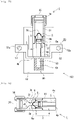
- Fig. 1(a) is a cross-sectional view of an actuator 1 in the case where the actuator 1 is cut in its axial direction.
- the actuator 1 has an actuator body 2 constituted by a first housing 3 and a second housing 4, and the side of the tip of the actuator body 2 (the side of an end portion of the second housing 4 opposite to an end portion thereof connected to the first housing 3) corresponds to the side of an output by the actuator 1, i.e., the side where an object on which a predetermined force acts is disposed.
- the first housing 3 and the second housing 4 are fixed to each other with a screw and are thereby integrated with each other.
- a combustion chamber 31 that is an internal space extending in an axial direction of the first housing 3 is formed and, inside the second housing 4, a through hole 33 that is an internal space extending similarly in an axial direction of the second housing 4 is formed.
- the combustion chamber 31 and the through hole 33 are separated from each other by a sealing member 8 described later, they are the internal spaces that are continuously disposed inside the actuator body 2.
- a surface on the side of the tip of the actuator body 2, i.e., a surface on the side of the tip of the second housing 4 forms an output surface 4b.
- the output surface 4b serves as the surface that faces the object on which the predetermined force acts during the use of the actuator 1.
- a metal output piston 6 is disposed in the through hole 33 in the second housing 4 of the actuator body 2, and the output piston 6 is held so as to be slidable in the through hole 33.
- Fig. 2 shows the details of the output piston 6 such that the positional relationship between the output piston 6 and the second housing 4 can be grasped.
- the output piston 6 is formed into a substantially shaft-like shape that extends along an axial direction of the through hole 33, and has an end portion (hereinafter referred to as a "first end portion") 6a on the side of the combustion chamber 31 and an end portion on the side of the output surface 4b, i.e., an end portion (hereinafter referred to as a "second end portion”) 6b that causes the predetermined force to act on the object, and an O-ring 6c is disposed around the output piston 6 such that the output piston 6 can slide smoothly in the through hole 33.
- the first end portion 6a is substantially protruded to the side of the combustion chamber 31 from an end surface of a fitted portion 4a of the second housing 4 that is fitted in the combustion chamber 31 of the first housing 3.
- a diameter d1 of the first end portion 6a is smaller than a diameter d0 of the through hole 33.
- a reduced diameter portion the inner diameter of which is reduced in the vicinity of the output surface 4b in the through hole 33 is formed, and the reduced diameter portion functions as a stopper portion 4c that comes into contact with the output piston 6 when the output piston 6 slides in the through hole 33, and stops the slide.
- a pre-ignition state shown in Fig. 1 the sealing member 8 is fixed such that a peripheral edge portion 8b of the sealing member 8 is disposed on the end surface of the fitted portion 4a of the second housing 4 that is part of an inner wall of the actuator body 2, and the peripheral edge portion 8b is buried in the first housing 3 in the vicinity of the fitted portion 4a.
- a central portion 8a of the sealing member 8 is in contact with an end surface of the first end portion 6a of the output piston 6.
- the first end portion 6a is disposed so as to be protruded in the first housing 3, and hence, as a result, the sealing member 8 is fixed in the actuator body 2 in a state in which the sealing member 8 is curved to the side of the initiator 20 in the pre-ignition state.
- the sealing member 8 is a plate-like member formed of a metal material, and separates the space in the actuator body 2 into a space including the combustion chamber 31 positioned on the side of the initiator 20 (corresponds to a first space according to the present invention) and a space including the through hole 33 positioned on the side of the output piston 6 (corresponds to a second space according to the present invention), and a combustion product generated by the gunpowder combustion in the initiator 20 is thereby sealed in the combustion chamber 31. Note that the movement of the sealing member 8 by the gunpowder combustion in the initiator 20 will be described later.
- the initiator 20 is an electrical ignition device, and a space for disposing gunpowder 22 is defined in a cup 21 by the cup 21, the surface of which is covered with an insulating cover.
- a metal header 24 is disposed in the space, and a tubular charge holder 23 is provided on an upper surface of the metal header 24.
- the gunpowder 22 is held by the charge holder 23.
- a bridge wire 26 that electrically connects one of conductive pins 28 and the metal header 24 is disposed at a bottom portion of the gunpowder 22.
- the two conductive pins 28 are fixed to the metal header 24 via an insulator 25 so as to be insulated from each other when voltage is not applied.
- an open port of the cup 21 from which the two conductive pins 28 supported by the insulator 25 extend is protected by a resin collar 27 in a state in which insulation characteristics between the conductive pins 28 are properly maintained.
- the initiator 20 when a voltage is applied between the two conductive pins 28 by an external power source, a current flows to the bridge wire 26, and the gunpowder 22 is thereby combusted. At this point, the combustion product generated by the combustion of the gunpowder 22 is jetted from an opening portion of the charge holder 23.
- the cross section of an initiator cap 14 is formed into a flange-like shape such that the initiator cap 14 is caught on an outer surface of the initiator 20, and the initiator cap 14 is fixed to the first housing 3 by using a screw. With this, the initiator 20 is fixed to the first housing 3 by using the initiator cap 14, and it is possible to prevent the initiator 20 itself from being disconnected from the actuator body 2 by pressure generated at the time of the ignition in the initiator 20.
- An example of the gunpowder 22 used in the actuator 1 preferably includes a gunpowder containing zirconium and potassium perchlorate (ZPP), a gunpowder containing titanium hydride and potassium perchlorate (THPP), a gunpowder containing titanium and potassium perchlorate (TiPP), a gunpowder containing aluminum and potassium perchlorate (APP), a gunpowder containing aluminum and bismuth oxide (ABO), a gunpowder containing aluminum and molybdenum oxide (AMO), a gunpowder containing aluminum and copper oxide (ACO), a gunpowder containing aluminum and iron oxide (AFO), or a gunpowder obtained by combining a plurality of the gunpowders.
- ZPP zirconium and potassium perchlorate
- THPP titanium hydride and potassium perchlorate
- TiPP titanium and potassium perchlorate
- APP aluminum and potassium perchlorate
- ABO aluminum and bismuth oxide
- Each gunpowder exhibits a characteristic that the gunpowder generates high-temperature high-pressure plasma during the combustion immediately after the ignition but, when the temperature is reduced to normal temperature and the combustion product condenses, generated pressure is sharply reduced because no gas component is contained. Note that another gunpowder other than the gunpowders described above may be used.
- a gas generating agent that is combusted by the combustion product generated by the combustion of the powder 22 and generates gas may be disposed in the combustion chamber 31.
- the gas generating agent includes single-base smokeless gunpowder containing 98 mass% of nitrocellulose, 0.8 mass% of diphenylamine, and 1.2 mass% of potassium sulfate.
- combustion completion time at the time of the combustion of the gas generating agent is significantly longer than that of the above gunpowder 22, but it is possible to change the combustion completion time of the gas generating agent by adjusting the dimensions, the size, the shape, and particularly the surface shape of the gas generating agent when the gas generating agent is disposed in the combustion chamber 31.
- the amount, the shape, and the disposition of the gas generating agent it is possible to appropriately adjust the generated pressure in the combustion chamber 31.
- Fig. 4 shows the configuration of the actuator 1 in the pre-combustion state
- the lower part of Fig. 4 shows the configuration of the actuator 1 in a state in which the actuator 1 is actuated by the combustion of the gunpowder 22 (hereinafter referred to as an "actuation state").
- actuation state a state in which the actuator 1 is actuated by the combustion of the gunpowder 22
- the positions of the peripheral edge portions 8b of the sealing members 8 are aligned and the states are arranged side by side and shown in the axial direction of the actuator 1.
- the position of the peripheral edge portion 8b common to both of the states is indicated by the origin X0. Further, in the pre-combustion state, the position of the central portion 8a of the sealing member 8 is indicated by X1, and the position of the end surface of the second end portion 6b of the output piston 6 is indicated by F1.
- the peripheral edge portion 8b is disposed on the end surface of the fitted portion 4a and the sealing member 8 is fixed on the side of the first housing 3 and, at this point, the sealing member 8 is curved such that the central portion 8a of the sealing member 8 is positioned on the side of the initiator 20 with respect to the peripheral edge portion 8b, and the central portion 8a of the sealing member 8 is in contact with the end surface of the first end portion 6a of the output piston 6.
- the central portion 8a of the sealing member 8 is positioned so as to face the cup 21 of the initiator 20. With this disposition, the sealing member 8 receives pressure by the combustion product released from the initiator 20 using its plate-like surface.
- the central portion 8a of the sealing member 8 is disposed at the position where the central portion 8a receives the pressure directly, and hence, as will be described later, it becomes easier for the central portion 8a to press the output piston 6.
- the sealing member 8 When the gunpowder 22 is combusted in the initiator 20, the combustion product is diffused in the combustion chamber 31, and the pressure in the combustion chamber 31 is increased. With this, the pressure is also applied to the sealing member 8. At this point, the central portion 8a is positioned in the central part of the plate-like sealing member 8, and hence the central portion 8a is the portion that is most likely to be deformed in the sealing member 8 of which the peripheral edge portion 8b is fixed. Accordingly, when the pressure is applied to the sealing member 8 by the gunpowder combustion, the sealing member 8 is deformed such that the central portion 8a presses the first end portion 6a of the output piston 6 to the side of the tip of the actuator 1.
- the sealing member 8 which is curved such that the central portion 8a is positioned on the side of the initiator 20 with respect to the peripheral edge portion 8b, is deformed so as to be curved such that the central portion 8a is positioned on the side of the output surface 4b opposite to the side of the initiator 20 by the gunpowder combustion.
- the position of the central portion 8a of the sealing member 8 is indicated by X2
- the position of the end surface of the second end portion 6b of the output piston 6 is indicated by F2. Consequently, the displacement amount of the central portion by the gunpowder combustion is given by (X2 - X1).
- the central portion 8a By causing the central portion 8a to move in response to the movement of the sealing member 8, it is possible to secure the large displacement amount of the sealing member 8 by the gunpowder combustion, and efficiently press the output piston 6. Further, in the pre-combustion state, the central portion 8a is in contact with the first end portion 6a, and hence it is possible to effectively convert the displacement of the central portion 8a of the sealing member 8 by the gunpowder combustion to the slide of the output piston 6 and, as a result, it is possible to obtain the protrusion amount (F2 - F1) of the output piston 6 by using the gunpowder combustion.
- the sealing member 8 is formed of the metal material, and hence, when the pressure is applied sharply to the sealing member 8 by the gunpowder combustion in the initiator 20, the sealing member 8 is substantially plastically deformed when the central portion 8a is displaced from the position (X1) on the side of the initiator 20 to the position (X2) on the side of the output surface 4b with respect to the peripheral edge portion 8b, as described above (see the actuation state in Fig. 4 ). That is, when the sharp pressure change is caused by the gunpowder combustion, the pressure that exceeds the yield point of the metal material forming the sealing member 8 is applied to the sealing member 8, and the sealing member 8 is plastically deformed.
- the output piston 6 is pressed by the sealing member 8, the entire output piston 6 is thereby caused to slide, and the output piston 6 protrudes from the output surface 4b.
- the sealing member 8 is made of metal and is formed into the plate-like shape, and hence it becomes possible to effectively drive the output piston 6 using the central portion 8a.
- the sealing member 8 is disposed so as to separate the combustion chamber 31 and the through hole 33 that are the internal spaces of the actuator body 2 from each other, and seal the combustion product generated by the initiator 20 in the combustion chamber 31. With this configuration, it is possible to effectively transmit the pressure generated by the combustion product to the output piston 6.
- the stopper portion 4c is designed such that F2 - F1 is equal to X2 - X1.
- the stopper portion 4c may be designed such that, after the pressing by the central portion 8a, the output piston 6 slides a predetermined distance in the through hole 33 and, as a result, F2 - F1 is larger than X2 - X1.
- Fig. 5 shows an electrical circuit interruption device 100 as an example of application of the actuator 1.
- the electrical circuit interruption device 100 is formed by fixing the actuator 1 to a conductor piece 50 via a housing 62.
- the conductor piece 50 forms part of the electrical circuit when the electrical circuit interruption device 100 is mounted to the electrical circuit, and is a plate piece constituted by a first connection portion 51 and a second connection portion 52 on both end sides, and a cut portion 53 between the connection portions.
- the first connection portion 51 and the second connection portion 52 are provided with connection holes 51a and 52a for connection to other conductors (e.g., a lead wire) in the electrical circuit, respectively.
- the conductor piece 50 shown in Fig. 5 is formed such that the first connection portion 51 and the second connection portion 52, and the cut portion 53 form a stepped shape, but the conductor piece 50 may also be formed such that the first connection portion 51, the second connection portion 52, and the cut portion 53 are disposed substantially on the same straight line.
- the cut portion 53 is fixed so as to be in contact with the output surface 4b of the actuator 1. Consequently, an end surface of the output piston 6 (the end surface of the second end portion 6b) in the actuator 1 faces the cut portion 53.
- the conductor piece 50 formed in this manner is the object in the above embodiment and, in particular, the cut portion 53 serves as a portion on the object on which the predetermined force from the actuator 1 acts.
- a box-shaped insulating portion 60 made of synthetic resin is formed, and an insulating space 61 is formed inside the insulating portion 60.
- the output piston 6 slides, a shearing force is caused to act on the cut portion 53 by kinetic energy of the output piston 6, and the cut portion 53 is thereby cut.
- continuity between the first connection portion 51 and the second connection portion 52 is interrupted. Note that a cut piece of the cut portion 53 that is cut by the output piston 6 is accommodated in the insulating space 61 in the insulating portion 60, and hence the above continuity interruption can be made more reliable.
- the actuator 1 in the electrical circuit interruption device 100 to which the actuator 1 according to the present invention is applied, it is possible to efficiently drive the actuator 1, which is extremely useful in the electrical circuit interruption device 100 that is to implement reliable continuity interruption when necessary.
- Another example of the application of the actuator 1 can include a punch or the like that punches a hole in the object.
- Fig. 6 shows a second embodiment of the present invention.
- Fig. 6 shows the schematic configuration of the actuator 1 according to the present embodiment in the pre-combustion state. Note that, in the present embodiment, configurations substantially identical to those in the first embodiment described above are designated by the same reference numerals, and the detailed description thereof will be omitted.
- a narrowed portion 3a is formed inside the first housing 3 such that the inner diameter of the combustion chamber 31 formed inside the first housing 3 is reduced with approach to the central portion 8a of the sealing member 8 from the side of the initiator 20 along the central axis of the actuator 1.
- the inner diameter of the combustion chamber 31 at a position where the inner diameter is smallest becomes substantially equal to d1 that is the outer diameter of the first end portion 6a of the output piston 6, and a passage 3b having a diameter of about d1 is formed in the combustion chamber 31 at a position facing the first end portion 6a.
- a clearance between an end portion of the passage 3b on the side of the output piston 6 and the central portion 8a of the sealing member 8 with which the first end portion 6a is in contact be as small as possible. Also by forming the narrowed portion 3a such that the inner diameter of the passage 3b is smaller than d1, it becomes possible to cause the combustion product to act on the central portion 8a of the sealing member 8 more intensively.
Landscapes
- Engineering & Computer Science (AREA)
- General Engineering & Computer Science (AREA)
- Life Sciences & Earth Sciences (AREA)
- Sustainable Development (AREA)
- Sustainable Energy (AREA)
- Power Engineering (AREA)
- Transportation (AREA)
- Mechanical Engineering (AREA)
- Actuator (AREA)
- Portable Nailing Machines And Staplers (AREA)
- Automotive Seat Belt Assembly (AREA)
Claims (5)
- Actionneur (1) comprenant :- un corps d'actionneur (2) ayant un orifice traversant (33) dans la direction axiale et une partie de piston de sortie (6) logée de façon à coulisser dans l'orifice traversant (33),- l'actionneur (1) étant configuré pour produire une force prédéterminée pour agir sur un objet en faisant sortir la partie de piston de sortie (6) pour venir en saillie par rapport à la surface extérieure (4b) du corps d'actionneur (2),l'actionneur (1) comprenant en outre :- un dispositif d'allumage (20) pour déclencher la poudre propulsive (22),le dispositif d'allumage (20) appliquant à la partie de piston de sortie (6) une énergie d'entraînement pour que la partie de piston de sortie (6) glisse du fait de la combustion de la poudre propulsive dans le dispositif d'allumage (20), et- un élément d'étanchéité (8) réalisé comme plaque métallique qui sépare l'espace du corps d'actionneur en un premier espace (31) dans lequel se trouve le dispositif d'allumage (20) et un second espace dans lequel se trouve la partie de piston de sortie (6) et qui ferme de façon étanche le produit de combustion généré par le dispositif d'allumage (20) dans le premier espace (31),- l'élément d'étanchéité (8) étant configuré pour être déformé par la combustion de la poudre propulsive dans le dispositif d'allumage (20) de façon qu'une partie centrale (8a) de l'élément d'étanchéité (8) soit déplacée vers un côté de la partie de piston de sortie (6) pour presser ainsi la partie de piston de sortie (6) en utilisant la partie centrale (8a) et en faisant glisser la partie de piston de sortie (6) dans l'orifice traversant (33),- le dispositif d'allumage (20) comportant une coupelle (21) qui forme l'espace pour recevoir la poudre propulsive (22), et- la partie centrale (8a) est placée pour faire face à la coupelle (21), actionneur caractérisé en ce queune partie de bord périphérique (8b) de l'élément d'étanchéité (8) est fixée à une paroi intérieure qui délimite l'espace dans le corps d'actionneur (2).
- Actionneur (1) selon la revendication 1,
dans lequel
l'élément d'étanchéité (8) est courbé pour que la partie centrale (8a) soit placée sur un côté du dispositif d'allumage (20) par rapport à la partie de bord périphérique (8b) dans l'état qui précède la combustion de la poudre propulsive dans le dispositif d'allumage (20), et- l'élément d'étanchéité (8) est incurvé pour que la partie centrale (8a) soit placée sur un côté opposé au côté du dispositif d'allumage (20) par rapport à la partie de bord périphérique (8b) par la combustion de la poudre propulsive dans le dispositif d'allumage (20). - Actionneur (1) selon la revendication 1 ou 2,
dans lequel
avec l'approche de la partie centrale (8a) de l'élément d'étanchéité (8) du dispositif d'allumage (20) selon l'axe central du corps d'actionneur (2), pour réduire la surface de la section de l'espace dans le corps d'actionneur (2) dans la direction perpendiculaire à l'axe central. - Actionneur (1) selon l'une quelconque des revendications 1 à 3, dans lequel
le dispositif d'allumage (20) a une partie de libération pour libérer le produit de combustion généré par la combustion de la poudre propulsive, et- la partie centrale (8a) de l'élément d'étanchéité (8) est disposée pour être en face de la partie de libération. - Actionneur (1) selon l'une quelconque des revendications 1 à 4, dans lequel
la partie d'extrémité (6a) de la partie de piston de sortie (6) est en contact avec la partie centrale (8a) de l'élément d'étanchéité (8) dans son état qui précède la combustion de la poudre propulsive dans le dispositif d'allumage (20).
Applications Claiming Priority (2)
| Application Number | Priority Date | Filing Date | Title |
|---|---|---|---|
| JP2016162871 | 2016-08-23 | ||
| PCT/JP2017/029982 WO2018038117A1 (fr) | 2016-08-23 | 2017-08-22 | Actionneur |
Publications (3)
| Publication Number | Publication Date |
|---|---|
| EP3506331A1 EP3506331A1 (fr) | 2019-07-03 |
| EP3506331A4 EP3506331A4 (fr) | 2020-03-11 |
| EP3506331B1 true EP3506331B1 (fr) | 2022-04-27 |
Family
ID=61246091
Family Applications (1)
| Application Number | Title | Priority Date | Filing Date |
|---|---|---|---|
| EP17843595.4A Active EP3506331B1 (fr) | 2016-08-23 | 2017-08-22 | Actionneur |
Country Status (5)
| Country | Link |
|---|---|
| US (1) | US10867764B2 (fr) |
| EP (1) | EP3506331B1 (fr) |
| JP (1) | JP7034075B2 (fr) |
| CN (1) | CN109564838B (fr) |
| WO (1) | WO2018038117A1 (fr) |
Families Citing this family (3)
| Publication number | Priority date | Publication date | Assignee | Title |
|---|---|---|---|---|
| US11353046B2 (en) | 2019-08-19 | 2022-06-07 | Cornell University | Microscale combustion for high density soft actuation |
| JP7494109B2 (ja) * | 2020-12-28 | 2024-06-03 | 株式会社ダイセル | 電気回路遮断装置 |
| CN119795920A (zh) * | 2024-05-22 | 2025-04-11 | 比亚迪股份有限公司 | 引爆式致动器、电机控制器、动力总成及车辆 |
Family Cites Families (32)
| Publication number | Priority date | Publication date | Assignee | Title |
|---|---|---|---|---|
| US2305436A (en) * | 1941-10-15 | 1942-12-15 | Gen Electric | Fuse device |
| US3334204A (en) * | 1965-09-09 | 1967-08-01 | Honeywell Inc | Pressure retard switch |
| FR2159628A5 (fr) * | 1971-11-05 | 1973-06-22 | France Etat | |
| US3802430A (en) | 1972-06-30 | 1974-04-09 | L Arnold | Disposable pyrotechnically powered injector |
| US4111221A (en) | 1976-01-28 | 1978-09-05 | Olsen Charles R | Low restriction, normally open valve construction having a deformable bladder |
| FR2561743B1 (fr) * | 1984-03-21 | 1986-09-05 | Aerospatiale | Vanne pyrotechnique |
| US5113108A (en) | 1988-11-04 | 1992-05-12 | Nec Corporation | Hermetically sealed electrostrictive actuator |
| FR2736973B1 (fr) * | 1995-07-21 | 1997-08-14 | Cryotechnologies | Activateur mecanique mu par un generateur de gaz pyrotechnique |
| DE19817133A1 (de) | 1998-04-19 | 1999-10-28 | Lell Peter | Powerswitch |
| JP4180707B2 (ja) * | 1998-10-15 | 2008-11-12 | 日油技研工業株式会社 | 緊急電源遮断具 |
| US8202979B2 (en) | 2002-02-20 | 2012-06-19 | Sirna Therapeutics, Inc. | RNA interference mediated inhibition of gene expression using chemically modified short interfering nucleic acid |
| FR2809461B1 (fr) * | 2000-05-29 | 2002-11-29 | Aerospatiale Matra Lanceurs St | Actionneur pyrotechnique a membrane deformable |
| FR2815544B1 (fr) | 2000-10-23 | 2003-02-14 | Poudres & Explosifs Ste Nale | Seringue sans aiguille securisee a architecture compacte |
| CA2452015C (fr) | 2001-07-05 | 2012-07-03 | Chiron Corporation | Polynucleotides codant des polypeptides de type c du vih antigeniques, polypeptides et leurs utilisations |
| US7063019B2 (en) | 2002-07-11 | 2006-06-20 | Autoliv Asp, Inc. | Assemblies including extendable, reactive charge-containing actuator devices |
| US20060027120A1 (en) * | 2002-07-11 | 2006-02-09 | Smith Bradley W | Assemblies including extendable, reactive charge-containing actuator devices |
| EP1473536B1 (fr) | 2003-04-30 | 2007-10-17 | Delphi Technologies, Inc. | Boîtier pour dispositif de découpe pyrotechnique avec élément d'allumage intégré |
| ATE439438T1 (de) | 2003-05-23 | 2009-08-15 | Sirna Therapeutics Inc | Durch rna-interferenz vermittelte hemmung der genexpression unter verwendung von chemisch modifizierter sina (short interfering nucleic acid) |
| US7239225B2 (en) * | 2003-10-17 | 2007-07-03 | Special Devices, Inc. | Pyrotechnic circuit breaker |
| CA2574881C (fr) | 2004-08-04 | 2013-01-08 | Amgen Inc. | Anticorps contre dkk-1 |
| EP2057195A4 (fr) | 2006-08-29 | 2010-05-12 | Forhumantech Co Ltd | Composition pharmaceutique pour la suppression de l'apoptose et méthode d'administration de ladite composition |
| JP2008206477A (ja) | 2007-02-27 | 2008-09-11 | National Cardiovascular Center | 無針注射器を用いた細胞播種法 |
| FR2957452B1 (fr) | 2010-03-15 | 2012-08-31 | Snpe Materiaux Energetiques | Interrupteur electrique a actionnement pyrotechnique |
| US8534174B2 (en) * | 2010-09-27 | 2013-09-17 | Power Tool Institute | Pyrotechnic actuator and power cutting tool with safety reaction system having such pyrotechnic actuator |
| JP4915473B1 (ja) * | 2010-12-27 | 2012-04-11 | ダイキン工業株式会社 | 切断装置 |
| JP2014049300A (ja) | 2012-08-31 | 2014-03-17 | Toyoda Gosei Co Ltd | 導通遮断装置 |
| FR3017240B1 (fr) * | 2014-02-04 | 2016-01-29 | Ncs Pyrotechnie Et Tech Sas | Coupe-circuit pyrotechnique |
| DE102014110825A1 (de) * | 2014-07-30 | 2014-09-18 | Peter Lell | Elektrischer Schalter, insbesondere für hohe Spannungen und/oder hohe Ströme |
| DE102014115397B4 (de) | 2014-10-22 | 2015-11-12 | Peter Lell | Pyrotechnische Antriebseinrichtung |
| JP6407759B2 (ja) * | 2015-02-17 | 2018-10-17 | 株式会社ダイセル | パイロ式アクチュエータ機構、注射器、及び点火器組立体 |
| US10332707B2 (en) | 2017-06-29 | 2019-06-25 | Daicel Corporation | Actuator |
| US10549038B2 (en) | 2017-06-29 | 2020-02-04 | Daicel Corporation | Syringe |
-
2017
- 2017-08-22 WO PCT/JP2017/029982 patent/WO2018038117A1/fr not_active Ceased
- 2017-08-22 EP EP17843595.4A patent/EP3506331B1/fr active Active
- 2017-08-22 JP JP2018535708A patent/JP7034075B2/ja active Active
- 2017-08-22 CN CN201780051679.9A patent/CN109564838B/zh active Active
-
2019
- 2019-02-22 US US16/282,992 patent/US10867764B2/en active Active
Also Published As
| Publication number | Publication date |
|---|---|
| CN109564838B (zh) | 2020-11-17 |
| US10867764B2 (en) | 2020-12-15 |
| EP3506331A4 (fr) | 2020-03-11 |
| US20190189374A1 (en) | 2019-06-20 |
| EP3506331A1 (fr) | 2019-07-03 |
| JP7034075B2 (ja) | 2022-03-11 |
| WO2018038117A1 (fr) | 2018-03-01 |
| CN109564838A (zh) | 2019-04-02 |
| JPWO2018038117A1 (ja) | 2019-06-24 |
Similar Documents
| Publication | Publication Date | Title |
|---|---|---|
| CN110073460B (zh) | 用于高电压大电流的中断的电断路器 | |
| EP3486935B1 (fr) | Actionneur | |
| US7063019B2 (en) | Assemblies including extendable, reactive charge-containing actuator devices | |
| JP6407759B2 (ja) | パイロ式アクチュエータ機構、注射器、及び点火器組立体 | |
| JP4242399B2 (ja) | 特に高電流強さ用電気回路の分離装置 | |
| US20160336131A1 (en) | Fuse having an explosion chamber | |
| CN108369878A (zh) | 一种烟火断路器 | |
| US10867764B2 (en) | Actuator | |
| CN103065868B (zh) | 带有烟火致动器的三相电短路器 | |
| US20060027120A1 (en) | Assemblies including extendable, reactive charge-containing actuator devices | |
| CN114556511A (zh) | 快速断路开关 | |
| US7772958B2 (en) | Load shedder | |
| EP3646362B1 (fr) | Actionneur | |
| CN114729796A (zh) | 用于提供预定烟火能量输出的方法和系统 | |
| US20240222053A1 (en) | Pyrotechnic circuit interrupter | |
| EP3857587B1 (fr) | Commutateur à actionneur pyrotechnique | |
| JP6632433B2 (ja) | アクチュエータ | |
| WO2023152907A1 (fr) | Dispositif de commutation de circuit électrique | |
| JP7034167B2 (ja) | アクチュエータ | |
| EP4318527A1 (fr) | Dispositif de rupture du circuit électrique |
Legal Events
| Date | Code | Title | Description |
|---|---|---|---|
| STAA | Information on the status of an ep patent application or granted ep patent |
Free format text: STATUS: THE INTERNATIONAL PUBLICATION HAS BEEN MADE |
|
| PUAI | Public reference made under article 153(3) epc to a published international application that has entered the european phase |
Free format text: ORIGINAL CODE: 0009012 |
|
| STAA | Information on the status of an ep patent application or granted ep patent |
Free format text: STATUS: REQUEST FOR EXAMINATION WAS MADE |
|
| 17P | Request for examination filed |
Effective date: 20190311 |
|
| AK | Designated contracting states |
Kind code of ref document: A1 Designated state(s): AL AT BE BG CH CY CZ DE DK EE ES FI FR GB GR HR HU IE IS IT LI LT LU LV MC MK MT NL NO PL PT RO RS SE SI SK SM TR |
|
| AX | Request for extension of the european patent |
Extension state: BA ME |
|
| DAV | Request for validation of the european patent (deleted) | ||
| DAX | Request for extension of the european patent (deleted) | ||
| RIN1 | Information on inventor provided before grant (corrected) |
Inventor name: MASUMOTO, TAKAYA |
|
| A4 | Supplementary search report drawn up and despatched |
Effective date: 20200207 |
|
| RIC1 | Information provided on ipc code assigned before grant |
Ipc: H01H 39/00 20060101AFI20200203BHEP Ipc: F42B 3/00 20060101ALI20200203BHEP |
|
| GRAP | Despatch of communication of intention to grant a patent |
Free format text: ORIGINAL CODE: EPIDOSNIGR1 |
|
| STAA | Information on the status of an ep patent application or granted ep patent |
Free format text: STATUS: GRANT OF PATENT IS INTENDED |
|
| INTG | Intention to grant announced |
Effective date: 20211209 |
|
| GRAS | Grant fee paid |
Free format text: ORIGINAL CODE: EPIDOSNIGR3 |
|
| GRAA | (expected) grant |
Free format text: ORIGINAL CODE: 0009210 |
|
| STAA | Information on the status of an ep patent application or granted ep patent |
Free format text: STATUS: THE PATENT HAS BEEN GRANTED |
|
| AK | Designated contracting states |
Kind code of ref document: B1 Designated state(s): AL AT BE BG CH CY CZ DE DK EE ES FI FR GB GR HR HU IE IS IT LI LT LU LV MC MK MT NL NO PL PT RO RS SE SI SK SM TR |
|
| REG | Reference to a national code |
Ref country code: GB Ref legal event code: FG4D |
|
| REG | Reference to a national code |
Ref country code: CH Ref legal event code: EP |
|
| REG | Reference to a national code |
Ref country code: DE Ref legal event code: R096 Ref document number: 602017056672 Country of ref document: DE |
|
| REG | Reference to a national code |
Ref country code: AT Ref legal event code: REF Ref document number: 1487603 Country of ref document: AT Kind code of ref document: T Effective date: 20220515 |
|
| REG | Reference to a national code |
Ref country code: IE Ref legal event code: FG4D |
|
| REG | Reference to a national code |
Ref country code: LT Ref legal event code: MG9D |
|
| REG | Reference to a national code |
Ref country code: NL Ref legal event code: MP Effective date: 20220427 |
|
| REG | Reference to a national code |
Ref country code: AT Ref legal event code: MK05 Ref document number: 1487603 Country of ref document: AT Kind code of ref document: T Effective date: 20220427 |
|
| PG25 | Lapsed in a contracting state [announced via postgrant information from national office to epo] |
Ref country code: NL Free format text: LAPSE BECAUSE OF FAILURE TO SUBMIT A TRANSLATION OF THE DESCRIPTION OR TO PAY THE FEE WITHIN THE PRESCRIBED TIME-LIMIT Effective date: 20220427 |
|
| PG25 | Lapsed in a contracting state [announced via postgrant information from national office to epo] |
Ref country code: SE Free format text: LAPSE BECAUSE OF FAILURE TO SUBMIT A TRANSLATION OF THE DESCRIPTION OR TO PAY THE FEE WITHIN THE PRESCRIBED TIME-LIMIT Effective date: 20220427 Ref country code: PT Free format text: LAPSE BECAUSE OF FAILURE TO SUBMIT A TRANSLATION OF THE DESCRIPTION OR TO PAY THE FEE WITHIN THE PRESCRIBED TIME-LIMIT Effective date: 20220829 Ref country code: NO Free format text: LAPSE BECAUSE OF FAILURE TO SUBMIT A TRANSLATION OF THE DESCRIPTION OR TO PAY THE FEE WITHIN THE PRESCRIBED TIME-LIMIT Effective date: 20220727 Ref country code: LT Free format text: LAPSE BECAUSE OF FAILURE TO SUBMIT A TRANSLATION OF THE DESCRIPTION OR TO PAY THE FEE WITHIN THE PRESCRIBED TIME-LIMIT Effective date: 20220427 Ref country code: HR Free format text: LAPSE BECAUSE OF FAILURE TO SUBMIT A TRANSLATION OF THE DESCRIPTION OR TO PAY THE FEE WITHIN THE PRESCRIBED TIME-LIMIT Effective date: 20220427 Ref country code: GR Free format text: LAPSE BECAUSE OF FAILURE TO SUBMIT A TRANSLATION OF THE DESCRIPTION OR TO PAY THE FEE WITHIN THE PRESCRIBED TIME-LIMIT Effective date: 20220728 Ref country code: FI Free format text: LAPSE BECAUSE OF FAILURE TO SUBMIT A TRANSLATION OF THE DESCRIPTION OR TO PAY THE FEE WITHIN THE PRESCRIBED TIME-LIMIT Effective date: 20220427 Ref country code: ES Free format text: LAPSE BECAUSE OF FAILURE TO SUBMIT A TRANSLATION OF THE DESCRIPTION OR TO PAY THE FEE WITHIN THE PRESCRIBED TIME-LIMIT Effective date: 20220427 Ref country code: BG Free format text: LAPSE BECAUSE OF FAILURE TO SUBMIT A TRANSLATION OF THE DESCRIPTION OR TO PAY THE FEE WITHIN THE PRESCRIBED TIME-LIMIT Effective date: 20220727 Ref country code: AT Free format text: LAPSE BECAUSE OF FAILURE TO SUBMIT A TRANSLATION OF THE DESCRIPTION OR TO PAY THE FEE WITHIN THE PRESCRIBED TIME-LIMIT Effective date: 20220427 |
|
| PG25 | Lapsed in a contracting state [announced via postgrant information from national office to epo] |
Ref country code: RS Free format text: LAPSE BECAUSE OF FAILURE TO SUBMIT A TRANSLATION OF THE DESCRIPTION OR TO PAY THE FEE WITHIN THE PRESCRIBED TIME-LIMIT Effective date: 20220427 Ref country code: PL Free format text: LAPSE BECAUSE OF FAILURE TO SUBMIT A TRANSLATION OF THE DESCRIPTION OR TO PAY THE FEE WITHIN THE PRESCRIBED TIME-LIMIT Effective date: 20220427 Ref country code: LV Free format text: LAPSE BECAUSE OF FAILURE TO SUBMIT A TRANSLATION OF THE DESCRIPTION OR TO PAY THE FEE WITHIN THE PRESCRIBED TIME-LIMIT Effective date: 20220427 Ref country code: IS Free format text: LAPSE BECAUSE OF FAILURE TO SUBMIT A TRANSLATION OF THE DESCRIPTION OR TO PAY THE FEE WITHIN THE PRESCRIBED TIME-LIMIT Effective date: 20220827 |
|
| REG | Reference to a national code |
Ref country code: DE Ref legal event code: R097 Ref document number: 602017056672 Country of ref document: DE |
|
| PG25 | Lapsed in a contracting state [announced via postgrant information from national office to epo] |
Ref country code: SM Free format text: LAPSE BECAUSE OF FAILURE TO SUBMIT A TRANSLATION OF THE DESCRIPTION OR TO PAY THE FEE WITHIN THE PRESCRIBED TIME-LIMIT Effective date: 20220427 Ref country code: SK Free format text: LAPSE BECAUSE OF FAILURE TO SUBMIT A TRANSLATION OF THE DESCRIPTION OR TO PAY THE FEE WITHIN THE PRESCRIBED TIME-LIMIT Effective date: 20220427 Ref country code: RO Free format text: LAPSE BECAUSE OF FAILURE TO SUBMIT A TRANSLATION OF THE DESCRIPTION OR TO PAY THE FEE WITHIN THE PRESCRIBED TIME-LIMIT Effective date: 20220427 Ref country code: EE Free format text: LAPSE BECAUSE OF FAILURE TO SUBMIT A TRANSLATION OF THE DESCRIPTION OR TO PAY THE FEE WITHIN THE PRESCRIBED TIME-LIMIT Effective date: 20220427 Ref country code: DK Free format text: LAPSE BECAUSE OF FAILURE TO SUBMIT A TRANSLATION OF THE DESCRIPTION OR TO PAY THE FEE WITHIN THE PRESCRIBED TIME-LIMIT Effective date: 20220427 Ref country code: CZ Free format text: LAPSE BECAUSE OF FAILURE TO SUBMIT A TRANSLATION OF THE DESCRIPTION OR TO PAY THE FEE WITHIN THE PRESCRIBED TIME-LIMIT Effective date: 20220427 |
|
| PLBE | No opposition filed within time limit |
Free format text: ORIGINAL CODE: 0009261 |
|
| STAA | Information on the status of an ep patent application or granted ep patent |
Free format text: STATUS: NO OPPOSITION FILED WITHIN TIME LIMIT |
|
| PG25 | Lapsed in a contracting state [announced via postgrant information from national office to epo] |
Ref country code: MC Free format text: LAPSE BECAUSE OF FAILURE TO SUBMIT A TRANSLATION OF THE DESCRIPTION OR TO PAY THE FEE WITHIN THE PRESCRIBED TIME-LIMIT Effective date: 20220427 Ref country code: AL Free format text: LAPSE BECAUSE OF FAILURE TO SUBMIT A TRANSLATION OF THE DESCRIPTION OR TO PAY THE FEE WITHIN THE PRESCRIBED TIME-LIMIT Effective date: 20220427 |
|
| REG | Reference to a national code |
Ref country code: CH Ref legal event code: PL |
|
| 26N | No opposition filed |
Effective date: 20230130 |
|
| PG25 | Lapsed in a contracting state [announced via postgrant information from national office to epo] |
Ref country code: LU Free format text: LAPSE BECAUSE OF NON-PAYMENT OF DUE FEES Effective date: 20220822 Ref country code: LI Free format text: LAPSE BECAUSE OF NON-PAYMENT OF DUE FEES Effective date: 20220831 Ref country code: CH Free format text: LAPSE BECAUSE OF NON-PAYMENT OF DUE FEES Effective date: 20220831 |
|
| REG | Reference to a national code |
Ref country code: BE Ref legal event code: MM Effective date: 20220831 |
|
| PG25 | Lapsed in a contracting state [announced via postgrant information from national office to epo] |
Ref country code: SI Free format text: LAPSE BECAUSE OF FAILURE TO SUBMIT A TRANSLATION OF THE DESCRIPTION OR TO PAY THE FEE WITHIN THE PRESCRIBED TIME-LIMIT Effective date: 20220427 |
|
| PG25 | Lapsed in a contracting state [announced via postgrant information from national office to epo] |
Ref country code: IE Free format text: LAPSE BECAUSE OF NON-PAYMENT OF DUE FEES Effective date: 20220822 |
|
| PG25 | Lapsed in a contracting state [announced via postgrant information from national office to epo] |
Ref country code: BE Free format text: LAPSE BECAUSE OF NON-PAYMENT OF DUE FEES Effective date: 20220831 |
|
| PG25 | Lapsed in a contracting state [announced via postgrant information from national office to epo] |
Ref country code: IT Free format text: LAPSE BECAUSE OF FAILURE TO SUBMIT A TRANSLATION OF THE DESCRIPTION OR TO PAY THE FEE WITHIN THE PRESCRIBED TIME-LIMIT Effective date: 20220427 |
|
| PG25 | Lapsed in a contracting state [announced via postgrant information from national office to epo] |
Ref country code: HU Free format text: LAPSE BECAUSE OF FAILURE TO SUBMIT A TRANSLATION OF THE DESCRIPTION OR TO PAY THE FEE WITHIN THE PRESCRIBED TIME-LIMIT; INVALID AB INITIO Effective date: 20170822 |
|
| PG25 | Lapsed in a contracting state [announced via postgrant information from national office to epo] |
Ref country code: CY Free format text: LAPSE BECAUSE OF FAILURE TO SUBMIT A TRANSLATION OF THE DESCRIPTION OR TO PAY THE FEE WITHIN THE PRESCRIBED TIME-LIMIT Effective date: 20220427 |
|
| PG25 | Lapsed in a contracting state [announced via postgrant information from national office to epo] |
Ref country code: MK Free format text: LAPSE BECAUSE OF FAILURE TO SUBMIT A TRANSLATION OF THE DESCRIPTION OR TO PAY THE FEE WITHIN THE PRESCRIBED TIME-LIMIT Effective date: 20220427 |
|
| PG25 | Lapsed in a contracting state [announced via postgrant information from national office to epo] |
Ref country code: TR Free format text: LAPSE BECAUSE OF FAILURE TO SUBMIT A TRANSLATION OF THE DESCRIPTION OR TO PAY THE FEE WITHIN THE PRESCRIBED TIME-LIMIT Effective date: 20220427 |
|
| PG25 | Lapsed in a contracting state [announced via postgrant information from national office to epo] |
Ref country code: MT Free format text: LAPSE BECAUSE OF FAILURE TO SUBMIT A TRANSLATION OF THE DESCRIPTION OR TO PAY THE FEE WITHIN THE PRESCRIBED TIME-LIMIT Effective date: 20220427 |
|
| PG25 | Lapsed in a contracting state [announced via postgrant information from national office to epo] |
Ref country code: BG Free format text: LAPSE BECAUSE OF FAILURE TO SUBMIT A TRANSLATION OF THE DESCRIPTION OR TO PAY THE FEE WITHIN THE PRESCRIBED TIME-LIMIT Effective date: 20220427 |
|
| PG25 | Lapsed in a contracting state [announced via postgrant information from national office to epo] |
Ref country code: BG Free format text: LAPSE BECAUSE OF FAILURE TO SUBMIT A TRANSLATION OF THE DESCRIPTION OR TO PAY THE FEE WITHIN THE PRESCRIBED TIME-LIMIT Effective date: 20220427 |
|
| PGFP | Annual fee paid to national office [announced via postgrant information from national office to epo] |
Ref country code: DE Payment date: 20250820 Year of fee payment: 9 |
|
| PGFP | Annual fee paid to national office [announced via postgrant information from national office to epo] |
Ref country code: GB Payment date: 20250821 Year of fee payment: 9 |
|
| PGFP | Annual fee paid to national office [announced via postgrant information from national office to epo] |
Ref country code: FR Payment date: 20250828 Year of fee payment: 9 |