EP3506533A1 - Erfassungsvorrichtung und -system - Google Patents
Erfassungsvorrichtung und -system Download PDFInfo
- Publication number
- EP3506533A1 EP3506533A1 EP17211188.2A EP17211188A EP3506533A1 EP 3506533 A1 EP3506533 A1 EP 3506533A1 EP 17211188 A EP17211188 A EP 17211188A EP 3506533 A1 EP3506533 A1 EP 3506533A1
- Authority
- EP
- European Patent Office
- Prior art keywords
- processing device
- optical
- sensors
- sensing
- optical coupling
- Prior art date
- Legal status (The legal status is an assumption and is not a legal conclusion. Google has not performed a legal analysis and makes no representation as to the accuracy of the status listed.)
- Granted
Links
Images


Classifications
-
- H—ELECTRICITY
- H04—ELECTRIC COMMUNICATION TECHNIQUE
- H04B—TRANSMISSION
- H04B10/00—Transmission systems employing electromagnetic waves other than radio-waves, e.g. infrared, visible or ultraviolet light, or employing corpuscular radiation, e.g. quantum communication
- H04B10/80—Optical aspects relating to the use of optical transmission for specific applications, not provided for in groups H04B10/03 - H04B10/70, e.g. optical power feeding or optical transmission through water
- H04B10/806—Arrangements for feeding power
- H04B10/807—Optical power feeding, i.e. transmitting power using an optical signal
-
- A—HUMAN NECESSITIES
- A61—MEDICAL OR VETERINARY SCIENCE; HYGIENE
- A61B—DIAGNOSIS; SURGERY; IDENTIFICATION
- A61B5/00—Measuring for diagnostic purposes; Identification of persons
- A61B5/0002—Remote monitoring of patients using telemetry, e.g. transmission of vital signals via a communication network
- A61B5/0015—Remote monitoring of patients using telemetry, e.g. transmission of vital signals via a communication network characterised by features of the telemetry system
- A61B5/0017—Remote monitoring of patients using telemetry, e.g. transmission of vital signals via a communication network characterised by features of the telemetry system transmitting optical signals
-
- A—HUMAN NECESSITIES
- A61—MEDICAL OR VETERINARY SCIENCE; HYGIENE
- A61B—DIAGNOSIS; SURGERY; IDENTIFICATION
- A61B5/00—Measuring for diagnostic purposes; Identification of persons
- A61B5/68—Arrangements of detecting, measuring or recording means, e.g. sensors, in relation to patient
- A61B5/6801—Arrangements of detecting, measuring or recording means, e.g. sensors, in relation to patient specially adapted to be attached to or worn on the body surface
-
- A—HUMAN NECESSITIES
- A61—MEDICAL OR VETERINARY SCIENCE; HYGIENE
- A61B—DIAGNOSIS; SURGERY; IDENTIFICATION
- A61B5/00—Measuring for diagnostic purposes; Identification of persons
- A61B5/68—Arrangements of detecting, measuring or recording means, e.g. sensors, in relation to patient
- A61B5/6801—Arrangements of detecting, measuring or recording means, e.g. sensors, in relation to patient specially adapted to be attached to or worn on the body surface
- A61B5/6802—Sensor mounted on worn items
- A61B5/6804—Garments; Clothes
-
- A—HUMAN NECESSITIES
- A61—MEDICAL OR VETERINARY SCIENCE; HYGIENE
- A61B—DIAGNOSIS; SURGERY; IDENTIFICATION
- A61B2560/00—Constructional details of operational features of apparatus; Accessories for medical measuring apparatus
- A61B2560/02—Operational features
- A61B2560/0204—Operational features of power management
- A61B2560/0214—Operational features of power management of power generation or supply
-
- A—HUMAN NECESSITIES
- A61—MEDICAL OR VETERINARY SCIENCE; HYGIENE
- A61B—DIAGNOSIS; SURGERY; IDENTIFICATION
- A61B2562/00—Details of sensors; Constructional details of sensor housings or probes; Accessories for sensors
- A61B2562/02—Details of sensors specially adapted for in-vivo measurements
- A61B2562/0271—Thermal or temperature sensors
-
- A—HUMAN NECESSITIES
- A61—MEDICAL OR VETERINARY SCIENCE; HYGIENE
- A61B—DIAGNOSIS; SURGERY; IDENTIFICATION
- A61B2562/00—Details of sensors; Constructional details of sensor housings or probes; Accessories for sensors
- A61B2562/14—Coupling media or elements to improve sensor contact with skin or tissue
- A61B2562/146—Coupling media or elements to improve sensor contact with skin or tissue for optical coupling
-
- A—HUMAN NECESSITIES
- A61—MEDICAL OR VETERINARY SCIENCE; HYGIENE
- A61B—DIAGNOSIS; SURGERY; IDENTIFICATION
- A61B5/00—Measuring for diagnostic purposes; Identification of persons
- A61B5/01—Measuring temperature of body parts ; Diagnostic temperature sensing, e.g. for malignant or inflamed tissue
-
- A—HUMAN NECESSITIES
- A61—MEDICAL OR VETERINARY SCIENCE; HYGIENE
- A61B—DIAGNOSIS; SURGERY; IDENTIFICATION
- A61B5/00—Measuring for diagnostic purposes; Identification of persons
- A61B5/02—Detecting, measuring or recording for evaluating the cardiovascular system, e.g. pulse, heart rate, blood pressure or blood flow
- A61B5/024—Measuring pulse rate or heart rate
- A61B5/02438—Measuring pulse rate or heart rate with portable devices, e.g. worn by the patient
-
- A—HUMAN NECESSITIES
- A61—MEDICAL OR VETERINARY SCIENCE; HYGIENE
- A61B—DIAGNOSIS; SURGERY; IDENTIFICATION
- A61B5/00—Measuring for diagnostic purposes; Identification of persons
- A61B5/44—Detecting, measuring or recording for evaluating the integumentary system, e.g. skin, hair or nails
- A61B5/441—Skin evaluation, e.g. for skin disorder diagnosis
- A61B5/443—Evaluating skin constituents, e.g. elastin, melanin, water
-
- H—ELECTRICITY
- H04—ELECTRIC COMMUNICATION TECHNIQUE
- H04B—TRANSMISSION
- H04B10/00—Transmission systems employing electromagnetic waves other than radio-waves, e.g. infrared, visible or ultraviolet light, or employing corpuscular radiation, e.g. quantum communication
- H04B10/25—Arrangements specific to fibre transmission
-
- H—ELECTRICITY
- H04—ELECTRIC COMMUNICATION TECHNIQUE
- H04B—TRANSMISSION
- H04B10/00—Transmission systems employing electromagnetic waves other than radio-waves, e.g. infrared, visible or ultraviolet light, or employing corpuscular radiation, e.g. quantum communication
- H04B10/25—Arrangements specific to fibre transmission
- H04B10/2589—Bidirectional transmission
-
- H—ELECTRICITY
- H04—ELECTRIC COMMUNICATION TECHNIQUE
- H04B—TRANSMISSION
- H04B10/00—Transmission systems employing electromagnetic waves other than radio-waves, e.g. infrared, visible or ultraviolet light, or employing corpuscular radiation, e.g. quantum communication
- H04B10/40—Transceivers
-
- H—ELECTRICITY
- H04—ELECTRIC COMMUNICATION TECHNIQUE
- H04B—TRANSMISSION
- H04B10/00—Transmission systems employing electromagnetic waves other than radio-waves, e.g. infrared, visible or ultraviolet light, or employing corpuscular radiation, e.g. quantum communication
- H04B10/80—Optical aspects relating to the use of optical transmission for specific applications, not provided for in groups H04B10/03 - H04B10/70, e.g. optical power feeding or optical transmission through water
- H04B10/806—Arrangements for feeding power
Definitions
- Examples of the disclosure relate to a sensing apparatus and system.
- they relate to a sensing apparatus and system which can be worn by a subject.
- Apparatus that can be used for sensing are known. Such apparatus could be wearable apparatus that may be worn by the subject. This may enable parameters such as the temperature of the subject, the humidity of the subject's skin, the presence of chemicals or analytes in the environment around the subject, or any other suitable parameters to be monitored for extended periods of time.
- an apparatus comprising: sensing means configured to sense one or more parameters; optical output means configured to provide an optical output signal indicative of data obtained by the sensing means; optical input means configured to receive an optical input signal and convert the optical input signal to electrical power; and storage means configured to store the electrical power obtained by the optical input means and enable the power to be provided to the sensing means and the optical output means; wherein the optical output means comprises one or more light emitting diodes and optical coupling means where the optical coupling means are configured to couple the apparatus to a processing device to enable data obtained by the sensing means to be transmitted to the processing device.
- the optical input means may comprise one or more photodiodes and optical coupling means where the optical coupling means are configured to enable light from a processing device to be detected by the one or more photodiodes.
- the optical coupling means may comprise at least one bi-directional light guide.
- the apparatus may be thermally insulated from the processing device.
- the apparatus may be comprised within a separate device to the processing device.
- the sensing means may comprise digital sensing means configured to provide a digital output.
- the optical coupling means may be configured to receive a control signal from the processing device to control the digital sensing means.
- the apparatus may comprise voltage to time conversion means configured to convert an analogue output of the sensing means to a digital output.
- the storage means may comprise a super capacitor.
- the sensing means may comprise temperature sensing means.
- the temperature sensing means may be thermally insulated from the optical output means and the optical input means.
- the apparatus may be comprised within a wearable device.
- the sensing means may be configured to directly contact a subject in use.
- the optical coupling means may comprise a first optical coupling means and a second optical coupling means; wherein the first optical coupling means are configured to enable the data obtained by the sensing means to be transmitted to the processing device; and wherein the second optical coupling means are configured to enable the light from the processing device to be detected by the one or more photodiodes.
- a sensing system comprising an apparatus described above and a processing device.
- the processing device may be comprised within a wearable device.
- an apparatus comprising: one or more sensors configured to sense a parameter; an optical output configured to provide an optical output signal indicative of data obtained by the one or more sensors; an optical input configured to receive an optical input signal and convert the optical input means to electrical power; and a power source configured to store the electrical power obtained by the optical input and enable the power to be provided to the one or more sensors and the optical output; wherein the optical output comprises one or more light emitting diodes and one or more optical coupling components where the optical coupling components are configured to couple the apparatus to a processing device to enable data obtained by the one or more sensors to be transmitted to the processing device.
- Examples of the disclosure relate to a sensing apparatus 1 and system 21.
- the sensing apparatus 1 can be worn by a subject. This could enable an accurate measurement of parameters relating to the subject, such as the subject's temperature, to be made.
- the sensing apparatus 1 is configured to send data to a processing device 23 via an optical output 5.
- the sensing apparatus 1 may also obtain power and/or control signals, from the processing device 23, via an optical input 7. This enables the sensing apparatus 1 to be thermally insulated from the processing device 23 because there is no need for any direct electrical connection between the sensing apparatus 1 and the processing device 23. This may improve the accuracy of measurements made by the sensing apparatus 1.
- Fig. 1 schematically illustrates an apparatus 1 according to examples of the disclosure.
- the apparatus 1 is a sensing apparatus 1.
- the apparatus 1 comprises one or more sensors 3, an optical output 5, an optical input 7 and a power source 9.
- the one or more sensors 3 may provide sensing means.
- the one or more sensors 3 may comprise any means which may be configured to sense a parameter.
- the sensors 3 may be configured to provide an electrical output signal dependent upon the parameter.
- the parameter may comprise a biometric parameter of a subject.
- the biometric parameter may comprise any time varying signal that is generated by the subject's body.
- the biometric parameter may comprise an autonomic parameter.
- the autonomic parameter may be controlled subconsciously by the subject.
- the biometric parameters could comprises temperature, humidity, blood oxygen levels, hear rate, audio signals, pressure, presence of one or more analytes or any other suitable parameters.
- the parameter could comprise a parameter of the environment in which the subject is located.
- the parameter could comprise the ambient temperature, the presence of humidity or other chemicals, ambient light, electromagnetic radiation levels, noise or any other suitable parameter.
- the one or more sensors 3 may comprise one or more temperature sensors.
- the one or more temperature sensors 3 could comprise any suitable type of sensors.
- the one or more temperature sensors 3 could comprise, thermistors, resistance temperature detectors, diodes, an integrated thermometer circuit, a digital thermometer configured to provide a digital output or any other suitable type of temperature sensors.
- Other types of temperature sensors 3 could be used in other examples of the disclosure.
- the apparatus1 may also comprise an analogue to digital converter.
- an analogue to digital converter may be provided to enable a digital output comprising the data obtained by the integrated thermometer circuit to be provided.
- the analogue to digital converter could be a voltage to time converter or any other suitable type of converter. An example of a voltage to time converter that could be used in some examples of the disclosure is shown in Fig. 4 .
- the one or more sensors 3 are configured to enable the parameters relating to a subject to be measured.
- the subject could be a person or animal who is wearing the apparatus 1.
- the one or more sensors 3 may be positioned within the apparatus 1 so that when a subject wears the apparatus 1 the one or more sensors 3 are positioned adjacent, or in close proximity to, the skin of the subject.
- the one or more sensors 3 may be positioned within the apparatus 1 so that they are in direct contact with the skin of the subject. This enables the one or more sensors 3 to directly contact the subject when the apparatus 1 is in use.
- a protective layer may be provided between the one or more sensors 3 and the skin of the subject.
- the protective layer could be configured to enable the parameter that is to be sensed to pass through the protective layer so that it can be sensed by the one or more sensors 3.
- the protective layer may be thermally conductive.
- the protective layer may be permeable to water.
- the one or more sensors 3 are coupled to the optical output 5. This may enable data obtained by the one or more sensors 3 to be provided to the optical output 5.
- the optical output 5 comprises means for converting an electrical signal received from the one or more sensors 3 into an optical output signal.
- the optical output signal could comprise infrared light, light in the visible range of the spectrum or light having any other suitable frequency.
- the optical output 5 could comprise one or more light emitting diodes and optical coupling means.
- the optical coupling means comprises one or more optical components that are configured to optically couple the apparatus 1 to a processing device 23. This enables an optical output signal that is transmitted by the apparatus 1 to be received by a processing device 23. This enables data obtained by the one or more sensors 3 to be transmitted to the processing device 23.
- An example processing device 23 is shown in Fig. 2 .
- the apparatus 1 also comprises an optical input 7.
- the optical input 7 comprises means for converting an optical input signal into an electrical signal.
- the optical input signal could be received from the processing device 23 or any other suitable device.
- the optical input 7 may comprise control signals received from the processing device 23.
- the optical input 7 may be coupled to the one or more sensors 3 to enable a control signal received via the optical input 7 to be provided to the one or more sensors 3.
- the control signal may trigger the one or more sensors 3 to make a reading. This may enable the one or more sensors 3 to be remotely controlled by the processing device 23 via the optical input 7.
- the optical input 7 could comprise one or more photodiodes and optical coupling means.
- the optical coupling means comprises one or more optical components that are configured to optically couple the apparatus 1 to a processing device 23. This enables an optical output signal that is transmitted by the processing device 23 to be received by the apparatus 1. This enables data from the processing device 23, or any other suitable device, to be detected by the one or more photodiodes.
- the same optical coupling means could be coupled to both the optical input 7 and the optical output 5. In other examples a separate optical coupling means could be provided for the optical output 5 and the optical input 7.
- the power source 9 comprises storage means for storing energy which may be used to power the apparatus 1.
- the optical input 7 may also be coupled to the power source 9. This may enable signals received via the optical input 7 to be used to charge to power source 9.
- the power source 9 could be a low leakage capacitor, a super capacitor or any other suitable energy storage means.
- the power source 9 is coupled to the one or more sensors 3 and the optical output 5 to enable power to be provided from the power source 9 to the one or more sensors 3 and the optical output 5.
- the apparatus 1 may be provided within a wearable device. This could enable the apparatus 1 to be used for an extended period of time.
- the wearable device could be worn for a period of hours of even days and data relating to the subject and/or the environment around the subject could be collected throughout that time.
- the wearable device could be attached to a strap which could be wrapped around the torso, or any other suitable part of the subject's body.
- the apparatus 1 could be provided within a wearable garment, such as a shirt, which could be worn by the subject.
- the apparatus 1 could be detached from the strap or garment in order to enable the strap or garment to be washed or otherwise cleaned.
- the apparatus 1 could be provided within a sensing pad that could be adhered or otherwise attached to the subject's body.
- Other means for enabling a subject to wear the apparatus 1, or attaching the apparatus to a subject's body, could be used in other examples of the disclosure.
- the apparatus 1 may comprise additional components that are not shown in Fig. 1 .
- the apparatus 1 could comprise one or more additional sensors which could be configured to detect other biometric parameters such as heart rate, or other parameters relating to the subject. This may enable the same sensing apparatus 1 to be used to detect a plurality of different parameters.
- Fig. 2 illustrates an example sensing system 21 comprising an apparatus 1, optical coupling means 25 and a processing device 23.
- the apparatus 1 may be an apparatus as shown in Fig. 1 .
- Corresponding reference numerals are used for corresponding features.
- the one or more sensors 3 are provided within an insulated area 27 and the other components of the apparatus 1, including the optical output 5, the optical input 7 and the power source 9 are provided outside of the insulated area 27.
- the one or more sensors 3 provided within the insulated area 27 could comprise one or more temperature sensors 3 or any other type of sensor s which may be sensitive to temperature.
- One or more electrical connections may be provided through the insulated area 27.
- the electrical connections may be between the one or more sensors 3 and the other components of the apparatus 1.
- the electrical connections provided through the insulated area may be as short and thin as possible to reduce the amount of heat transferred to the one or more sensors 3.
- the insulated area 27 ensures that the one or more sensors 3 are thermally insulated from the optical output 5, the optical input 7 and the power source 9. This prevents any heating of the other components of the apparatus 1 such as the optical output 5, the optical input 7 and the power source 9 from affecting the measurements made by the one or more sensors 3. This therefore may improve the accuracy of the measurements made by the one or more sensors 3.
- the apparatus 1 could be configured differently.
- the optical output 5 and/or the optical input 7 could be provided within the thermally insulated area 27. This configuration could be used where the power generated by the other components of the apparatus 1 is not high enough to cause a significant error in the measurements made by the one or more sensors 3.
- the thermally insulated area 27 may comprise an area of the apparatus 1 which is surrounded by, or at least partially surrounded by, a thermally insulating material.
- the thermally insulating material could comprise a polymer or any other suitable insulating material.
- the optical coupling means 25 provide means for coupling the apparatus 1 to a processing device 23.
- the optical coupling means 25 comprises one or more optical components which provide a channel though which the optical signals can be transmitted and/or received.
- the optical coupling means may comprise one or more light guides.
- the optical coupling means 25 may comprise at least one bi-directional light guide. In some examples different light guides could be coupled to the optical input 7 and the optical output 5. In other examples the same light guide could be coupled to both the optical input and the optical output 5.
- the system comprises one optical coupling means 25.
- the system 21 could comprise a plurality of optical coupling means.
- the plurality of optical coupling means 25 could comprise a first optical coupling means and a second optical coupling means.
- the first optical coupling means may be configured to enable the data obtained by the one or more sensors 3 to be transmitted to the processing device 23.
- the second optical coupling means may be configured to enable light from the processing device to be transmitted to the one or more photodiodes in the optical input 7.
- the optical coupling means 25 does not contain any electrical connections. That is there is no path for direct current provided via the optical coupling means 25. There is no galvanic connection between the apparatus 1 and the processing device 23. This means that there is no heating of the apparatus 1 caused by any electrical connections to the processing device 23. Also there is no heat transferred via the electrical connections.
- the optical coupling means 25 may act to thermally insulate the apparatus 1 from the processing device 23. That is the optical coupling means 25 may comprise a thermally insulating material so as to prevent heat from the processing device 23 from being transferred to the apparatus 1.
- the processing device 23 could also be a wearable device.
- the processing device 23 could be attached to a strap which could be wrapped around the torso, or any other suitable part of the subject's body.
- the apparatus 1 could be attached to the same strap as the processing device 23.
- the apparatus 1 and the processing device 23 could be provided at different locations along the same strap.
- the processing device 23 could be provided within a wearable garment, such as a shirt, which could be worn by the subject. In such examples the apparatus 1 and the processing device 23 could be provided at different locations within the wearable garment.
- the processing device 23 could be a device that is not worn by the subject.
- it could be a computer, a mobile phone, a table or other suitable electronic device.
- This processing device could be configured to be coupled to the apparatus 1 to enable data from the apparatus 1 to be transmitted to the processing device 23.
- the processing device 23, as shown in Fig. 2 comprises any suitable components which are needed to receive data from the apparatus 1 and perform any necessary processing on the data to enable an output indicative of the sensed parameter to be provided.
- the processing device 23 comprises an optical input 20, an optical output 22, controlling circuitry 24 and a main power source 26.
- the optical input 20 comprises means for converting an optical input signal into an electrical signal.
- the optical input signal could be received from the apparatus 1 and may contain data obtained by the one or more sensors 3. This may enable the processing device 23 to obtain data indicative of the sensed parameter.
- the optical input 20 could comprise one or more photodiodes, or any other suitable means, which may be coupled to the optical coupling means 25.
- the optical output 22 comprises means for converting an electrical input signal into an optical signal.
- the optical signal could be transmitted to the apparatus 1.
- the optical signal could comprise a control signal which may enable the apparatus 1 to be remotely controlled by the processing device 23.
- the optical signal could also be used to provide power from the processing device 23 to the apparatus 1.
- the optical output could comprise one or more light emitting diodes, or any other suitable means, which may be coupled to the optical coupling means 25.
- the main power source 26 comprises storage means for storing energy which may be used to power the processing device 23.
- the main power source 26 could comprise a chargeable battery, a capacitor or any other suitable type of energy storage means.
- the main power source 26 may be coupled to the other components of the processing device 23 to enable power to be provided to the other components of the processing device 23.
- system 21 is configured so that the main power source 26 provides power to the apparatus 1.
- the power could be provided to the apparatus 1 as optical signals which may be transmitted through via the optical output 22 and the optical coupling means 25.
- the main power source 26 for the system 21 is provided in the processing device 23 this reduces the size of the power source 9 needed in the apparatus 1. This also means that a user of the system 21 only needs to charge a single power source 26 to enable two separate devices to be used.
- the processing device 23 also comprises controlling circuitry 24.
- the controlling circuitry 24 may comprise processing circuitry and memory circuitry.
- the controlling circuitry 24 may comprise means for controlling the processing device 23 and/or means for providing control signals for the apparatus 1.
- the controlling circuitry 24 may also provide means for processing the data obtained from the one or more sensors 3 to provide an indication of the sensed parameter and/or means for storing information indicative of the sensed parameter.
- the controlling circuitry 24 may provide means for processing the data obtained from one or more temperature sensors 3 to determine the temperature of the subject and/or means for storing information indicative of the temperature of the subject.
- the optical coupling means 25 enables data to be transferred between the sensing apparatus 1 and the processing device 23.
- the optical coupling means 25 may also enable power to be transferred from the main power source 26 of the processing device 23 or other main power source.
- the apparatus 1 is comprised within a separate device to the processing device 23.
- This enables the apparatus 1 and the processing device 23 to be positioned in different locations.
- the apparatus 1 when the system is in use to measure a subject's temperature the apparatus 1 could be positioned underneath the subject's armpit or on the side of their torso where an accurate and/or reliable temperature measurement may be made.
- the processing device 23 could be positioned on the subject's sternum or anywhere else where it may be convenient and/or comfortable to locate the processing device 23. In other examples, where the sensing apparatus 1 is configured to sense other parameters the apparatus 1 could be located in a different location.
- the apparatus 1 and the processing device 23 are provided as separate components which can be positioned in different locations.
- the apparatus 1 and the processing device 23 could be provided within the same device.
- the device comprises thermal insulation to insulate the sensing apparatus 1 from the processing device.
- the optical coupling means 25, which may be provided within the device, also ensures that no direct electrical connection is provided between the processing device 23 and the sensing apparatus 1.
- Fig. 3 illustrates components of an apparatus 1 according to examples of the disclosure.
- the components of the apparatus 1 shown in Fig. 3 comprises an optical input 7, a power source 9 and one or more sensors 3.
- the components of the apparatus 1 shown in Fig. 3 enable a measurement to be made in response to an optical input signal. It is to be appreciated that some components of the apparatus 1, such as the optical output 5 are not shown in Fig. 3 .
- the optical input 7 comprises a photodiode.
- the photodiode receives an optical input signal 33 via the optical coupling means 25.
- the optical input signal 33 may be received from the processing device 23.
- the photodiode is coupled to a direct current to direct current (DC to DC) converter 33.
- the DC to DC converter 33 may comprise any means configured to increase the voltage of the electrical signal provided by the photodiode in response to the optical input signal 33.
- the DC to DC converter 33 could comprise a charge pump or any other suitable type of DC to DC converter.
- the output of the DC to DC converter is provided to the power source 9. This enables the optical energy received via the photodiode to be converted to electrical energy and stored in the power source 9.
- the power source 9 could be a capacitor, a low leakage capacitor, a battery or any other suitable type of power source.
- the one or more temperature sensors 3 comprise an integrated thermometer circuit.
- the integrated thermometer circuit has a low sampling frequency and low power consumption so that the circuit can be powered with the optical energy obtained via the photodiode and stored in the power source 9.
- Other types of sensors could be used in other examples of the disclosure.
- the sensors 3 could be configured to sense parameters other than temperature.
- the output of the DC to DC converter 33 is also provided to the one or more sensors 3.
- the signal from the DC to DC converter 33 may trigger a measurement reading from the one or more sensors 3. In some examples the measurement may be triggered once sufficient energy has been stored in the power source 9.
- the example components shown in Fig. 3 therefore enable optical power that is received by the optical input 7 to be converted to electrical energy and used to power the apparatus 1. This means that only a small power source for storing the required energy is needed within the apparatus 1. This reduces the number of components in the apparatus 1 that might heat up during use which could affect temperature measurements and/or measurements of other parameters.
- Fig. 4 illustrates components of an apparatus 1 according to an example of the disclosure.
- the components of the apparatus 1 shown in Fig. 4 comprise one or more sensors 3, an integrator 41, a comparator 43, an optical pulse generator 45 and an optical output 5.
- the components of the apparatus 1 shown in Fig. 4 enable an optical output signal indicative of the parameter sensed by the one or more sensors 3 to be provided. It is to be appreciated that some components of the apparatus 1, such as the optical input 7 are not shown in Fig. 3 .
- the example apparatus 1 in Fig. 4 comprises conversion means configured to convert the analogue output from the sensor 3 to a digital output.
- the conversion means comprise voltage to time conversion means.
- Other types of conversion means could be used in other examples of the disclosure.
- the one or more sensors 3 comprises an analogue sensor.
- the analogue sensor could comprise an integrated circuit or any other suitable type of sensors.
- the one or more sensors 3 provide an analogue output signal where the voltage of the output signal is indicative of the sensed parameter.
- the one or more sensors 3 are coupled to the integrator 41 so that the analogue output signal from the one or more sensors 3 is provided to the integrator 41.
- the integrator 41 comprises any means which may perform a time integration of the analogue signal obtained from the one or more sensors 3.
- the integrator 41 is coupled to the comparator 43 so that the output of the integrator 41 is provided as an input to the comparator 43.
- the comparator 43 is configured to compare the voltage provided by the integrator 41 to a reference voltage 44.
- the comparator 43 provides an output indicative of the difference between the voltage provided by the integrator 41 to a reference voltage 44.
- the comparator may comprise a high gain differential amplifier or any other suitable means.
- the comparator 43 is coupled to the pulse generator 45 so that the output of the comparator 43 is provided as an input to the pulse generator 45.
- the pulse generator 45 may comprise any means configured to convert the output of the comparator 43 into a pulsed signal 47.
- the pulse generator 45 may comprise an edge detector which may be configured to generate a pulse when a transition is detected in the input signal.
- Other types of pulse generator 45 may be used in other examples of the disclosure.
- the interval between the pulses within the pulsed signal 47 is indicative of the difference between the voltage provided by the integrator 41 to a reference voltage 44.
- the interval between the pulses within the pulsed signal 47 is therefore indicative of the parameter by the one or more sensors 3.
- the pulse generator could use pulse width encoding so that the duration of the pluses within the pulsed signal 47 is indicative of the parameter by the one or more sensors 3.
- the pulse generator 45 is coupled to the optical output 5 so that the pulsed signal 47 is provided to the optical output 5.
- the optical output 5 comprises a light emitting diode.
- the light emitting diode converts the pulsed signal 47 into a series of flashes of light where the duration of the flashes indicates the parameter sensed by the one or more sensors 3.
- the flashes of light emitted by the light emitting diode can be transmitted to the processing device 23 via the optical coupling means 25.
- the processing device 23 can then determine the sensed parameter from the intervals between the received flashes of light.
- the processing device 23 may be configured to quantify the sensed parameter from the intervals between the received flashes of light.
- the one or more sensors 3 comprises an analogue sensor.
- a digital sensor could be used.
- the digital sensor could be a digital thermometer or any other suitable means.
- the coupling means 25 and the optical input 7 may be configured to receive a control signal from the processing device 23 to control the digital sensor.
- the coupling means could be bi-directional to enable an output signal to be transmitted from the optical output 5 to the processing device 23 via the optical coupling means 25.
- the one or more sensors 3 within the apparatus 1 comprises a digital sensor or an analogue sensor may depend on a number of factors such as the processing capability of the processing device 23.
- the user of the analogue sensor may require more processing to be performed by the processing device 23 and so may be used in systems 21 where the processing device 23 has a higher processing capacity.
- the digital sensor 21 could be used in systems 21 where the processing device 23 has a lower processing capability.
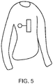
- Fig. 5 illustrates a garment 51 comprising an example sensing system 21.
- both the apparatus 1 and the processing device 23 are provided within the same garment 51.
- the apparatus 1 could be provided in the garment 51 while the processing device 23 could be located elsewhere.
- the garment 51 comprises an item of clothing which is configured to be worn by a subject.
- the subject could be a person or an animal which may require temperature measurements to be made or any other suitable parameter to be sensed.
- the garment 51 comprises a shirt.
- Other items of clothing could be used in other examples of the disclosure.
- the apparatus 1 is positioned within the garment 51 so that when the garment 51 is worn by the subject the one or more sensors 3 are located underneath the subject's armpit or on the side of the subject's torso.
- the apparatus 1 may comprise one or more temperature sensors 3 configured to measure the temperature of the subject.
- the garment 51 may be configured so that the one or more temperature sensors 3 are located underneath the subject's armpit or on the side of the subject's torso as this may enable a reliable temperature measurement to be made.
- the apparatus 1 could be located in different positions in other examples of the disclosure.
- the garment 51 may be configured so that the one or more sensors 3 are located on the chest or other suitable part of the subject which may be exposed to the environmental parameters.
- the processing device 23 is positioned within the garment 51 so that when the garment 51 is worn by the subject the processing device 23 is located over the subject's sternum. This could be a comfortable place for the processing device 23 to be located as the processing device 23 may be bulkier and heavier than the apparatus 1.
- the processing device 23 could be located in different positions in other examples of the disclosure.
- An optical coupling means 25 is provided between the apparatus 1 and processing device 23.
- the optical coupling means 25 could be woven into the fabric of the garment 51.
- additional sensors could be provided within the garment 51.
- the additional sensors could be configured to detect biometric signals such a bioelectric signals or biomechanical signals.
- the apparatus 1 is provided within a garment 51 which could be worn for a long period of time, for example several hours, this enables parameters relating to a subject and/or the environment of the subject to be monitored over that time period.
- Examples of the disclosure provide for a sensing apparatus 1 which can provide accurate readings because the sensing apparatus 1 is thermally and electrically isolated from the processing device 23. This prevents heating caused by components of the processing device and/or the electrical connections within the processing device 23 from affecting the readings made by the one or more sensors 3.
- the one or more sensors 3 comprise temperature sensors this will enable more accurate temperature readings to be made as they will not be affected by the heat generated by other electrical connections and/or components within the processing device 23.
- the temperature sensing apparatus 1 could provide temperature measurements with an accuracy of 0.1 °C.
- the one or more sensors 3 may comprise sensors where the ambient temperature can affect the readings made by the sensors.
- the sensors could comprise a field effect transistor (FET) or a graphene field effect transistor (GFET) where the conductivity of the channel is used to sense a parameter.
- FET field effect transistor
- GFET graphene field effect transistor
- the conductivity of the channel may also be dependent upon the temperature of the sensor. Therefore, by thermally insulating the one or more sensors 3 from the processing device 23 this may enable more accurate readings to be obtained.
- the processing device 23 may also comprise one or more additional sensors.
- the additional sensors could be configured to detect biometric parameters of the user, or any other suitable parameters.
- the biometric parameter could be a bioelectrical signal which could comprise at least one of an electrocardiogram signal, electroencephalogram signal, electromyogram signal, electrooculogram signal, electrogastrogram signal, galvanic skin potential or any other suitable bioelectric signal.
- the one or more sensors 3 can be provided in direct contact with the skin of the subject because there is no direct electrical connection between the one or more sensors 3 which could interfere with the measurement of the bioelectrical signal. This therefore may enable examples of the disclosure to be used to obtain accurate measurements of two or more parameters of the subject simultaneously. For example it may be used to obtain accurate measurements of the temperature of the subject and also a bioelectrical signal of the subject.
- the processing device 23 may be configured to communicate data received from the apparatus 1 with or without local storage of the data in memory circuitry at the processing device 23 and with or without local processing of the data by circuitry or processors at the processing device 23.
- the data maybe measurement data obtained by the one or sensors 3 of the apparatus 1 or data produced by the processing of measurement data from the one or more sensors 3.
- the data may be stored in processed or unprocessed format remotely at one or more devices.
- the data may be stored in The Cloud or in any other suitable location.
- the data may be processed remotely at one or more devices.
- the data may be partially processed locally and partially processed remotely at one or more devices.
- the data may be communicated to the remote devices wirelessly via short range radio communications such as Wi-Fi or Bluetooth, for example, or over long range cellular radio links.
- the processing device 23 may comprise a communications interface such as, for example, a radio transceiver for communication of data.
- the processing of the data may be for the purpose of health monitoring, data aggregation, patient monitoring, vital signs monitoring or other purposes.
- coupled means operationally coupled. Any number of intervening components may be provided between coupled components, including zero intervening components.
- example or “for example” or “may” in the text denotes, whether explicitly stated or not, that such features or functions are present in at least the described example, whether described as an example or not, and that they can be, but are not necessarily, present in some of or all other examples.
- example “for example” or “may” refers to a particular instance in a class of examples.
- a property of the instance can be a property of only that instance or a property of the class or a property of a subclass of the class that includes some but not all of the instances in the class. It is therefore implicitly disclosed that a feature described with reference to one example but not with reference to another example, can where possible be used in that other example but does not necessarily have to be used in that other example.
Landscapes
- Life Sciences & Earth Sciences (AREA)
- Health & Medical Sciences (AREA)
- Engineering & Computer Science (AREA)
- Physics & Mathematics (AREA)
- Heart & Thoracic Surgery (AREA)
- Public Health (AREA)
- Pathology (AREA)
- Biomedical Technology (AREA)
- Veterinary Medicine (AREA)
- Medical Informatics (AREA)
- Molecular Biology (AREA)
- Surgery (AREA)
- Animal Behavior & Ethology (AREA)
- General Health & Medical Sciences (AREA)
- Biophysics (AREA)
- Computer Networks & Wireless Communication (AREA)
- Electromagnetism (AREA)
- Signal Processing (AREA)
- Measuring And Recording Apparatus For Diagnosis (AREA)
Priority Applications (3)
| Application Number | Priority Date | Filing Date | Title |
|---|---|---|---|
| EP17211188.2A EP3506533B1 (de) | 2017-12-29 | 2017-12-29 | Erfassungsvorrichtung und -system |
| US16/772,114 US12015449B2 (en) | 2017-12-29 | 2018-12-14 | Sensing apparatus and system |
| PCT/EP2018/084909 WO2019129505A1 (en) | 2017-12-29 | 2018-12-14 | Sensing apparatus and system |
Applications Claiming Priority (1)
| Application Number | Priority Date | Filing Date | Title |
|---|---|---|---|
| EP17211188.2A EP3506533B1 (de) | 2017-12-29 | 2017-12-29 | Erfassungsvorrichtung und -system |
Publications (2)
| Publication Number | Publication Date |
|---|---|
| EP3506533A1 true EP3506533A1 (de) | 2019-07-03 |
| EP3506533B1 EP3506533B1 (de) | 2022-03-30 |
Family
ID=60937587
Family Applications (1)
| Application Number | Title | Priority Date | Filing Date |
|---|---|---|---|
| EP17211188.2A Active EP3506533B1 (de) | 2017-12-29 | 2017-12-29 | Erfassungsvorrichtung und -system |
Country Status (3)
| Country | Link |
|---|---|
| US (1) | US12015449B2 (de) |
| EP (1) | EP3506533B1 (de) |
| WO (1) | WO2019129505A1 (de) |
Families Citing this family (1)
| Publication number | Priority date | Publication date | Assignee | Title |
|---|---|---|---|---|
| CN113375716B (zh) * | 2021-06-01 | 2023-06-20 | 国网重庆市电力公司电力科学研究院 | 基于多传感器数据融合的自供电输电线路在线监测系统 |
Citations (2)
| Publication number | Priority date | Publication date | Assignee | Title |
|---|---|---|---|---|
| EP0043929A2 (de) * | 1980-06-23 | 1982-01-20 | Asea Ab | Messanordnung mit optischer Fiber |
| EP1703360A2 (de) * | 2005-03-14 | 2006-09-20 | The Boeing Company | Verfahren und Vorrichtung für optisches Antreiben und Multiplexing verteilter faseroptischer Sensoren |
Family Cites Families (30)
| Publication number | Priority date | Publication date | Assignee | Title |
|---|---|---|---|---|
| DE3788811T2 (de) * | 1986-11-26 | 1994-04-28 | Terumo Corp | Elektronisches klinisches thermometer. |
| US5119679A (en) * | 1991-04-05 | 1992-06-09 | The Boeing Company | Optically powered and linked pressure transducer |
| US5528409A (en) * | 1994-10-13 | 1996-06-18 | Nt International, Inc. | Fiber-optic interface system |
| IL119076A0 (en) * | 1996-08-14 | 1996-11-14 | I S Medtech Ltd | Flow measurement |
| US7696901B2 (en) * | 2002-03-22 | 2010-04-13 | Schlumberger Technology Corporation | Methods and apparatus for photonic power conversion downhole |
| DE102004005793A1 (de) * | 2004-02-06 | 2005-08-25 | Daimlerchrysler Ag | Steuergerät mit Signalwandler |
| US7324035B2 (en) * | 2004-05-13 | 2008-01-29 | University Of Florida Research Foundation, Inc. | Amplifier with pulse coded output and remote signal reconstruction from the pulse output |
| JP4851330B2 (ja) * | 2004-07-02 | 2012-01-11 | 古河電気工業株式会社 | 光給電型センシングシステム |
| KR20070052781A (ko) | 2004-09-08 | 2007-05-22 | 앨러티스 메디칼 에이에스 | 센서 |
| US7366021B2 (en) * | 2005-05-04 | 2008-04-29 | Micron Technology, Inc. | Method and apparatus for sensing flash memory using delta sigma modulation |
| GB0517994D0 (en) * | 2005-09-05 | 2005-10-12 | Univ Glasgow | High voltage insulation monitoring sensor |
| US20070295713A1 (en) * | 2006-06-15 | 2007-12-27 | John Carlton-Foss | System and method for measuring core body temperature |
| US8180225B2 (en) * | 2006-12-20 | 2012-05-15 | Jan-Gustav Werthen | Optical data link |
| US7528760B2 (en) * | 2007-01-26 | 2009-05-05 | Texas Insturments Incorporated | Class D analog-to-digital converter |
| US7813646B2 (en) * | 2007-07-11 | 2010-10-12 | RLH Industries, Inc | Power over optical fiber system |
| US8139225B2 (en) * | 2007-10-24 | 2012-03-20 | Siemens Medical Solutions Usa, Inc. | System for processing patient monitoring power and data signals |
| US8185341B2 (en) * | 2008-05-30 | 2012-05-22 | Medisim Ltd. | Surface temperature profile |
| US9326708B2 (en) * | 2010-03-26 | 2016-05-03 | Medtronic Minimed, Inc. | Ambient temperature sensor systems and methods |
| US8573843B2 (en) * | 2010-11-05 | 2013-11-05 | Citizen Holdings Co., Ltd. | Temperature measuring device |
| DE102013219092B4 (de) * | 2013-09-23 | 2015-04-09 | Conti Temic Microelectronic Gmbh | Anordnung eines Temperatursensors mit einer elektrisch isolierenden Umhüllung |
| US9287831B2 (en) * | 2013-12-23 | 2016-03-15 | Analog Devices Global | Temperature stabilized circuitry |
| CN104068832A (zh) | 2014-06-20 | 2014-10-01 | 京东方科技集团股份有限公司 | 一种体表温度计及可佩戴显示装置 |
| JP6253608B2 (ja) * | 2015-03-16 | 2017-12-27 | 株式会社東芝 | アナログ/デジタル変換回路 |
| US10034609B2 (en) | 2015-11-05 | 2018-07-31 | Nano And Advanced Materials Institute Limited | Temperature sensor for tracking body temperature based on printable nanomaterial thermistor |
| US10598537B2 (en) * | 2015-12-17 | 2020-03-24 | Simmonds Precision Products, Inc. | Systems and methods for liquid level detection with optoelectronic interfaced dual thermistor bead sensor |
| US9793991B2 (en) * | 2016-03-15 | 2017-10-17 | Simmonds Precision Products, Inc. | Optically interfaced remote data concentrator |
| US9979480B1 (en) * | 2016-05-19 | 2018-05-22 | X Development Llc | Optical power and data |
| US9906300B2 (en) * | 2016-05-20 | 2018-02-27 | Rosemount Aerospace Inc. | Optically powered transducer module |
| US11672484B2 (en) * | 2016-12-16 | 2023-06-13 | Zoll Medical Corporation | Electrode falloff detection |
| CN106644166A (zh) | 2016-12-19 | 2017-05-10 | 天津市品通电力科技有限公司 | 一种基于磁耦隔离的双路测温仪表 |
-
2017
- 2017-12-29 EP EP17211188.2A patent/EP3506533B1/de active Active
-
2018
- 2018-12-14 US US16/772,114 patent/US12015449B2/en active Active
- 2018-12-14 WO PCT/EP2018/084909 patent/WO2019129505A1/en not_active Ceased
Patent Citations (2)
| Publication number | Priority date | Publication date | Assignee | Title |
|---|---|---|---|---|
| EP0043929A2 (de) * | 1980-06-23 | 1982-01-20 | Asea Ab | Messanordnung mit optischer Fiber |
| EP1703360A2 (de) * | 2005-03-14 | 2006-09-20 | The Boeing Company | Verfahren und Vorrichtung für optisches Antreiben und Multiplexing verteilter faseroptischer Sensoren |
Also Published As
| Publication number | Publication date |
|---|---|
| WO2019129505A1 (en) | 2019-07-04 |
| EP3506533B1 (de) | 2022-03-30 |
| US12015449B2 (en) | 2024-06-18 |
| US20210091860A1 (en) | 2021-03-25 |
Similar Documents
| Publication | Publication Date | Title |
|---|---|---|
| KR101964343B1 (ko) | 피부 저항 및 커패시턴스 측정들 사이의 단일 전극의 공유 | |
| US8930147B2 (en) | Multi-sensor patch and system | |
| US20170105646A1 (en) | Multi-parameter sensor system for measuring physiological signals | |
| US9295403B1 (en) | Multipurpose wearable electrical contact | |
| US9723986B1 (en) | Physiological parameter measuring system | |
| Rigi et al. | Wireless battery-free body temperature sensing device for key workers | |
| CN202891917U (zh) | 心电体温传感带 | |
| CN213043825U (zh) | 穿戴式电子设备及无线耳机 | |
| US12015449B2 (en) | Sensing apparatus and system | |
| CN111772601B (zh) | 一种温度检测指环及检测方法 | |
| Shen et al. | Design and implementation of a wearable, multiparameter physiological monitoring system for the study of human heat stress, cold stress, and thermal comfort | |
| Yun et al. | A flexible wireless sensor patch for real-time monitoring of heart rate and body temperature | |
| CN205433675U (zh) | 人体生理信息采集组件、人体生理参数测量设备和系统 | |
| CN108402560A (zh) | 一种具有心率监测的衣服 | |
| Welch et al. | Wearable sensing devices for human-machine interaction systems | |
| CN110063721A (zh) | 测量人体体征信息的智能鞋及体征测量方法、压电方法 | |
| CN212229795U (zh) | 一种耳塞式红外体温计及其监测预警系统 | |
| KR102471204B1 (ko) | 인체 신호 검출 헤드셋 장치 | |
| CN210354673U (zh) | 一种测量人体体征信息的智能鞋 | |
| JP6557611B2 (ja) | 脈拍測定装置 | |
| KR101694757B1 (ko) | 웨어러블 산소포화도 측정 시스템 | |
| CN222303914U (zh) | 一种柔性可穿戴信息感知的医养健康检测系统 | |
| US20250255495A1 (en) | Physiological Strain Sensor | |
| KR20240026023A (ko) | 비접촉 방식으로 대상체 온도측정이 가능한 근거리 무선통신 온도센싱태그 및 이를 포함하는 온도관리 시스템 | |
| CN215811315U (zh) | 一种蓝牙双系统测温手环 |
Legal Events
| Date | Code | Title | Description |
|---|---|---|---|
| PUAI | Public reference made under article 153(3) epc to a published international application that has entered the european phase |
Free format text: ORIGINAL CODE: 0009012 |
|
| STAA | Information on the status of an ep patent application or granted ep patent |
Free format text: STATUS: THE APPLICATION HAS BEEN PUBLISHED |
|
| AK | Designated contracting states |
Kind code of ref document: A1 Designated state(s): AL AT BE BG CH CY CZ DE DK EE ES FI FR GB GR HR HU IE IS IT LI LT LU LV MC MK MT NL NO PL PT RO RS SE SI SK SM TR |
|
| AX | Request for extension of the european patent |
Extension state: BA ME |
|
| RAP1 | Party data changed (applicant data changed or rights of an application transferred) |
Owner name: NOKIA TECHNOLOGIES OY |
|
| STAA | Information on the status of an ep patent application or granted ep patent |
Free format text: STATUS: REQUEST FOR EXAMINATION WAS MADE |
|
| 17P | Request for examination filed |
Effective date: 20191230 |
|
| RBV | Designated contracting states (corrected) |
Designated state(s): AL AT BE BG CH CY CZ DE DK EE ES FI FR GB GR HR HU IE IS IT LI LT LU LV MC MK MT NL NO PL PT RO RS SE SI SK SM TR |
|
| REG | Reference to a national code |
Ref country code: DE Ref legal event code: R079 Ref document number: 602017055153 Country of ref document: DE Free format text: PREVIOUS MAIN CLASS: H04B0010800000 Ipc: A61B0005010000 |
|
| RIC1 | Information provided on ipc code assigned before grant |
Ipc: H04B 10/80 20130101ALI20210902BHEP Ipc: A61B 5/01 20060101AFI20210902BHEP |
|
| GRAP | Despatch of communication of intention to grant a patent |
Free format text: ORIGINAL CODE: EPIDOSNIGR1 |
|
| STAA | Information on the status of an ep patent application or granted ep patent |
Free format text: STATUS: GRANT OF PATENT IS INTENDED |
|
| GRAJ | Information related to disapproval of communication of intention to grant by the applicant or resumption of examination proceedings by the epo deleted |
Free format text: ORIGINAL CODE: EPIDOSDIGR1 |
|
| GRAP | Despatch of communication of intention to grant a patent |
Free format text: ORIGINAL CODE: EPIDOSNIGR1 |
|
| INTG | Intention to grant announced |
Effective date: 20211014 |
|
| INTG | Intention to grant announced |
Effective date: 20211027 |
|
| GRAS | Grant fee paid |
Free format text: ORIGINAL CODE: EPIDOSNIGR3 |
|
| GRAA | (expected) grant |
Free format text: ORIGINAL CODE: 0009210 |
|
| STAA | Information on the status of an ep patent application or granted ep patent |
Free format text: STATUS: THE PATENT HAS BEEN GRANTED |
|
| AK | Designated contracting states |
Kind code of ref document: B1 Designated state(s): AL AT BE BG CH CY CZ DE DK EE ES FI FR GB GR HR HU IE IS IT LI LT LU LV MC MK MT NL NO PL PT RO RS SE SI SK SM TR |
|
| REG | Reference to a national code |
Ref country code: GB Ref legal event code: FG4D |
|
| REG | Reference to a national code |
Ref country code: CH Ref legal event code: EP |
|
| REG | Reference to a national code |
Ref country code: AT Ref legal event code: REF Ref document number: 1478455 Country of ref document: AT Kind code of ref document: T Effective date: 20220415 |
|
| REG | Reference to a national code |
Ref country code: DE Ref legal event code: R096 Ref document number: 602017055153 Country of ref document: DE |
|
| REG | Reference to a national code |
Ref country code: IE Ref legal event code: FG4D |
|
| REG | Reference to a national code |
Ref country code: LT Ref legal event code: MG9D |
|
| PG25 | Lapsed in a contracting state [announced via postgrant information from national office to epo] |
Ref country code: SE Free format text: LAPSE BECAUSE OF FAILURE TO SUBMIT A TRANSLATION OF THE DESCRIPTION OR TO PAY THE FEE WITHIN THE PRESCRIBED TIME-LIMIT Effective date: 20220330 Ref country code: RS Free format text: LAPSE BECAUSE OF FAILURE TO SUBMIT A TRANSLATION OF THE DESCRIPTION OR TO PAY THE FEE WITHIN THE PRESCRIBED TIME-LIMIT Effective date: 20220330 Ref country code: NO Free format text: LAPSE BECAUSE OF FAILURE TO SUBMIT A TRANSLATION OF THE DESCRIPTION OR TO PAY THE FEE WITHIN THE PRESCRIBED TIME-LIMIT Effective date: 20220630 Ref country code: LT Free format text: LAPSE BECAUSE OF FAILURE TO SUBMIT A TRANSLATION OF THE DESCRIPTION OR TO PAY THE FEE WITHIN THE PRESCRIBED TIME-LIMIT Effective date: 20220330 Ref country code: HR Free format text: LAPSE BECAUSE OF FAILURE TO SUBMIT A TRANSLATION OF THE DESCRIPTION OR TO PAY THE FEE WITHIN THE PRESCRIBED TIME-LIMIT Effective date: 20220330 Ref country code: BG Free format text: LAPSE BECAUSE OF FAILURE TO SUBMIT A TRANSLATION OF THE DESCRIPTION OR TO PAY THE FEE WITHIN THE PRESCRIBED TIME-LIMIT Effective date: 20220630 |
|
| REG | Reference to a national code |
Ref country code: NL Ref legal event code: MP Effective date: 20220330 |
|
| REG | Reference to a national code |
Ref country code: AT Ref legal event code: MK05 Ref document number: 1478455 Country of ref document: AT Kind code of ref document: T Effective date: 20220330 |
|
| PG25 | Lapsed in a contracting state [announced via postgrant information from national office to epo] |
Ref country code: LV Free format text: LAPSE BECAUSE OF FAILURE TO SUBMIT A TRANSLATION OF THE DESCRIPTION OR TO PAY THE FEE WITHIN THE PRESCRIBED TIME-LIMIT Effective date: 20220330 Ref country code: GR Free format text: LAPSE BECAUSE OF FAILURE TO SUBMIT A TRANSLATION OF THE DESCRIPTION OR TO PAY THE FEE WITHIN THE PRESCRIBED TIME-LIMIT Effective date: 20220701 Ref country code: FI Free format text: LAPSE BECAUSE OF FAILURE TO SUBMIT A TRANSLATION OF THE DESCRIPTION OR TO PAY THE FEE WITHIN THE PRESCRIBED TIME-LIMIT Effective date: 20220330 |
|
| PG25 | Lapsed in a contracting state [announced via postgrant information from national office to epo] |
Ref country code: NL Free format text: LAPSE BECAUSE OF FAILURE TO SUBMIT A TRANSLATION OF THE DESCRIPTION OR TO PAY THE FEE WITHIN THE PRESCRIBED TIME-LIMIT Effective date: 20220330 |
|
| PG25 | Lapsed in a contracting state [announced via postgrant information from national office to epo] |
Ref country code: SM Free format text: LAPSE BECAUSE OF FAILURE TO SUBMIT A TRANSLATION OF THE DESCRIPTION OR TO PAY THE FEE WITHIN THE PRESCRIBED TIME-LIMIT Effective date: 20220330 Ref country code: SK Free format text: LAPSE BECAUSE OF FAILURE TO SUBMIT A TRANSLATION OF THE DESCRIPTION OR TO PAY THE FEE WITHIN THE PRESCRIBED TIME-LIMIT Effective date: 20220330 Ref country code: RO Free format text: LAPSE BECAUSE OF FAILURE TO SUBMIT A TRANSLATION OF THE DESCRIPTION OR TO PAY THE FEE WITHIN THE PRESCRIBED TIME-LIMIT Effective date: 20220330 Ref country code: PT Free format text: LAPSE BECAUSE OF FAILURE TO SUBMIT A TRANSLATION OF THE DESCRIPTION OR TO PAY THE FEE WITHIN THE PRESCRIBED TIME-LIMIT Effective date: 20220801 Ref country code: ES Free format text: LAPSE BECAUSE OF FAILURE TO SUBMIT A TRANSLATION OF THE DESCRIPTION OR TO PAY THE FEE WITHIN THE PRESCRIBED TIME-LIMIT Effective date: 20220330 Ref country code: EE Free format text: LAPSE BECAUSE OF FAILURE TO SUBMIT A TRANSLATION OF THE DESCRIPTION OR TO PAY THE FEE WITHIN THE PRESCRIBED TIME-LIMIT Effective date: 20220330 Ref country code: CZ Free format text: LAPSE BECAUSE OF FAILURE TO SUBMIT A TRANSLATION OF THE DESCRIPTION OR TO PAY THE FEE WITHIN THE PRESCRIBED TIME-LIMIT Effective date: 20220330 Ref country code: AT Free format text: LAPSE BECAUSE OF FAILURE TO SUBMIT A TRANSLATION OF THE DESCRIPTION OR TO PAY THE FEE WITHIN THE PRESCRIBED TIME-LIMIT Effective date: 20220330 |
|
| PG25 | Lapsed in a contracting state [announced via postgrant information from national office to epo] |
Ref country code: PL Free format text: LAPSE BECAUSE OF FAILURE TO SUBMIT A TRANSLATION OF THE DESCRIPTION OR TO PAY THE FEE WITHIN THE PRESCRIBED TIME-LIMIT Effective date: 20220330 Ref country code: IS Free format text: LAPSE BECAUSE OF FAILURE TO SUBMIT A TRANSLATION OF THE DESCRIPTION OR TO PAY THE FEE WITHIN THE PRESCRIBED TIME-LIMIT Effective date: 20220730 Ref country code: AL Free format text: LAPSE BECAUSE OF FAILURE TO SUBMIT A TRANSLATION OF THE DESCRIPTION OR TO PAY THE FEE WITHIN THE PRESCRIBED TIME-LIMIT Effective date: 20220330 |
|
| REG | Reference to a national code |
Ref country code: DE Ref legal event code: R097 Ref document number: 602017055153 Country of ref document: DE |
|
| PG25 | Lapsed in a contracting state [announced via postgrant information from national office to epo] |
Ref country code: DK Free format text: LAPSE BECAUSE OF FAILURE TO SUBMIT A TRANSLATION OF THE DESCRIPTION OR TO PAY THE FEE WITHIN THE PRESCRIBED TIME-LIMIT Effective date: 20220330 |
|
| PLBE | No opposition filed within time limit |
Free format text: ORIGINAL CODE: 0009261 |
|
| STAA | Information on the status of an ep patent application or granted ep patent |
Free format text: STATUS: NO OPPOSITION FILED WITHIN TIME LIMIT |
|
| 26N | No opposition filed |
Effective date: 20230103 |
|
| PG25 | Lapsed in a contracting state [announced via postgrant information from national office to epo] |
Ref country code: SI Free format text: LAPSE BECAUSE OF FAILURE TO SUBMIT A TRANSLATION OF THE DESCRIPTION OR TO PAY THE FEE WITHIN THE PRESCRIBED TIME-LIMIT Effective date: 20220330 |
|
| PG25 | Lapsed in a contracting state [announced via postgrant information from national office to epo] |
Ref country code: IT Free format text: LAPSE BECAUSE OF FAILURE TO SUBMIT A TRANSLATION OF THE DESCRIPTION OR TO PAY THE FEE WITHIN THE PRESCRIBED TIME-LIMIT Effective date: 20220330 |
|
| REG | Reference to a national code |
Ref country code: CH Ref legal event code: PL |
|
| REG | Reference to a national code |
Ref country code: BE Ref legal event code: MM Effective date: 20221231 |
|
| PG25 | Lapsed in a contracting state [announced via postgrant information from national office to epo] |
Ref country code: LU Free format text: LAPSE BECAUSE OF NON-PAYMENT OF DUE FEES Effective date: 20221229 |
|
| PG25 | Lapsed in a contracting state [announced via postgrant information from national office to epo] |
Ref country code: LI Free format text: LAPSE BECAUSE OF NON-PAYMENT OF DUE FEES Effective date: 20221231 Ref country code: IE Free format text: LAPSE BECAUSE OF NON-PAYMENT OF DUE FEES Effective date: 20221229 Ref country code: CH Free format text: LAPSE BECAUSE OF NON-PAYMENT OF DUE FEES Effective date: 20221231 |
|
| PG25 | Lapsed in a contracting state [announced via postgrant information from national office to epo] |
Ref country code: FR Free format text: LAPSE BECAUSE OF NON-PAYMENT OF DUE FEES Effective date: 20221231 Ref country code: BE Free format text: LAPSE BECAUSE OF NON-PAYMENT OF DUE FEES Effective date: 20221231 |
|
| PG25 | Lapsed in a contracting state [announced via postgrant information from national office to epo] |
Ref country code: HU Free format text: LAPSE BECAUSE OF FAILURE TO SUBMIT A TRANSLATION OF THE DESCRIPTION OR TO PAY THE FEE WITHIN THE PRESCRIBED TIME-LIMIT; INVALID AB INITIO Effective date: 20171229 |
|
| PG25 | Lapsed in a contracting state [announced via postgrant information from national office to epo] |
Ref country code: CY Free format text: LAPSE BECAUSE OF FAILURE TO SUBMIT A TRANSLATION OF THE DESCRIPTION OR TO PAY THE FEE WITHIN THE PRESCRIBED TIME-LIMIT Effective date: 20220330 |
|
| PG25 | Lapsed in a contracting state [announced via postgrant information from national office to epo] |
Ref country code: MK Free format text: LAPSE BECAUSE OF FAILURE TO SUBMIT A TRANSLATION OF THE DESCRIPTION OR TO PAY THE FEE WITHIN THE PRESCRIBED TIME-LIMIT Effective date: 20220330 |
|
| PG25 | Lapsed in a contracting state [announced via postgrant information from national office to epo] |
Ref country code: MC Free format text: LAPSE BECAUSE OF FAILURE TO SUBMIT A TRANSLATION OF THE DESCRIPTION OR TO PAY THE FEE WITHIN THE PRESCRIBED TIME-LIMIT Effective date: 20220330 |
|
| PG25 | Lapsed in a contracting state [announced via postgrant information from national office to epo] |
Ref country code: MC Free format text: LAPSE BECAUSE OF FAILURE TO SUBMIT A TRANSLATION OF THE DESCRIPTION OR TO PAY THE FEE WITHIN THE PRESCRIBED TIME-LIMIT Effective date: 20220330 |
|
| PG25 | Lapsed in a contracting state [announced via postgrant information from national office to epo] |
Ref country code: MT Free format text: LAPSE BECAUSE OF FAILURE TO SUBMIT A TRANSLATION OF THE DESCRIPTION OR TO PAY THE FEE WITHIN THE PRESCRIBED TIME-LIMIT Effective date: 20220330 |
|
| PG25 | Lapsed in a contracting state [announced via postgrant information from national office to epo] |
Ref country code: TR Free format text: LAPSE BECAUSE OF FAILURE TO SUBMIT A TRANSLATION OF THE DESCRIPTION OR TO PAY THE FEE WITHIN THE PRESCRIBED TIME-LIMIT Effective date: 20220330 |
|
| PGFP | Annual fee paid to national office [announced via postgrant information from national office to epo] |
Ref country code: DE Payment date: 20251104 Year of fee payment: 9 |
|
| PGFP | Annual fee paid to national office [announced via postgrant information from national office to epo] |
Ref country code: GB Payment date: 20251114 Year of fee payment: 9 |