EP3509214B1 - Mikro- oder nanomechanische vorrichtung zur detektion von partikeln - Google Patents
Mikro- oder nanomechanische vorrichtung zur detektion von partikeln Download PDFInfo
- Publication number
- EP3509214B1 EP3509214B1 EP19150014.9A EP19150014A EP3509214B1 EP 3509214 B1 EP3509214 B1 EP 3509214B1 EP 19150014 A EP19150014 A EP 19150014A EP 3509214 B1 EP3509214 B1 EP 3509214B1
- Authority
- EP
- European Patent Office
- Prior art keywords
- platform
- beams
- detection device
- displacement
- particle
- Prior art date
- Legal status (The legal status is an assumption and is not a legal conclusion. Google has not performed a legal analysis and makes no representation as to the accuracy of the status listed.)
- Active
Links
Images



Classifications
-
- G—PHYSICS
- G01—MEASURING; TESTING
- G01N—INVESTIGATING OR ANALYSING MATERIALS BY DETERMINING THEIR CHEMICAL OR PHYSICAL PROPERTIES
- G01N15/00—Investigating characteristics of particles; Investigating permeability, pore-volume or surface-area of porous materials
- G01N15/10—Investigating individual particles
- G01N15/14—Optical investigation techniques, e.g. flow cytometry
-
- G—PHYSICS
- G01—MEASURING; TESTING
- G01H—MEASUREMENT OF MECHANICAL VIBRATIONS OR ULTRASONIC, SONIC OR INFRASONIC WAVES
- G01H13/00—Measuring resonant frequency
-
- G—PHYSICS
- G01—MEASURING; TESTING
- G01L—MEASURING FORCE, STRESS, TORQUE, WORK, MECHANICAL POWER, MECHANICAL EFFICIENCY, OR FLUID PRESSURE
- G01L1/00—Measuring force or stress, in general
- G01L1/10—Measuring force or stress, in general by measuring variations of frequency of stressed vibrating elements, e.g. of stressed strings
- G01L1/103—Measuring force or stress, in general by measuring variations of frequency of stressed vibrating elements, e.g. of stressed strings optical excitation or measuring of vibrations
-
- G—PHYSICS
- G01—MEASURING; TESTING
- G01L—MEASURING FORCE, STRESS, TORQUE, WORK, MECHANICAL POWER, MECHANICAL EFFICIENCY, OR FLUID PRESSURE
- G01L1/00—Measuring force or stress, in general
- G01L1/18—Measuring force or stress, in general using properties of piezo-resistive materials, i.e. materials of which the ohmic resistance varies according to changes in magnitude or direction of force applied to the material
-
- G—PHYSICS
- G01—MEASURING; TESTING
- G01N—INVESTIGATING OR ANALYSING MATERIALS BY DETERMINING THEIR CHEMICAL OR PHYSICAL PROPERTIES
- G01N29/00—Investigating or analysing materials by the use of ultrasonic, sonic or infrasonic waves; Visualisation of the interior of objects by transmitting ultrasonic or sonic waves through the object
- G01N29/02—Analysing fluids
- G01N29/022—Fluid sensors based on microsensors, e.g. quartz crystal-microbalance [QCM], surface acoustic wave [SAW] devices, tuning forks, cantilevers, flexural plate wave [FPW] devices
-
- G—PHYSICS
- G01—MEASURING; TESTING
- G01P—MEASURING LINEAR OR ANGULAR SPEED, ACCELERATION, DECELERATION, OR SHOCK; INDICATING PRESENCE, ABSENCE, OR DIRECTION, OF MOVEMENT
- G01P15/00—Measuring acceleration; Measuring deceleration; Measuring shock, i.e. sudden change of acceleration
- G01P15/02—Measuring acceleration; Measuring deceleration; Measuring shock, i.e. sudden change of acceleration by making use of inertia forces using solid seismic masses
- G01P15/08—Measuring acceleration; Measuring deceleration; Measuring shock, i.e. sudden change of acceleration by making use of inertia forces using solid seismic masses with conversion into electric or magnetic values
- G01P15/0802—Details
-
- H—ELECTRICITY
- H01—ELECTRIC ELEMENTS
- H01J—ELECTRIC DISCHARGE TUBES OR DISCHARGE LAMPS
- H01J49/00—Particle spectrometers or separator tubes
- H01J49/02—Details
- H01J49/04—Arrangements for introducing or extracting samples to be analysed, e.g. vacuum locks; Arrangements for external adjustment of electron- or ion-optical components
- H01J49/0409—Sample holders or containers
- H01J49/0413—Sample holders or containers for automated handling
-
- H—ELECTRICITY
- H01—ELECTRIC ELEMENTS
- H01J—ELECTRIC DISCHARGE TUBES OR DISCHARGE LAMPS
- H01J49/00—Particle spectrometers or separator tubes
- H01J49/26—Mass spectrometers or separator tubes
-
- G—PHYSICS
- G01—MEASURING; TESTING
- G01D—MEASURING NOT SPECIALLY ADAPTED FOR A SPECIFIC VARIABLE; ARRANGEMENTS FOR MEASURING TWO OR MORE VARIABLES NOT COVERED IN A SINGLE OTHER SUBCLASS; TARIFF METERING APPARATUS; MEASURING OR TESTING NOT OTHERWISE PROVIDED FOR
- G01D5/00—Mechanical means for transferring the output of a sensing member; Means for converting the output of a sensing member to another variable where the form or nature of the sensing member does not constrain the means for converting; Transducers not specially adapted for a specific variable
- G01D5/26—Mechanical means for transferring the output of a sensing member; Means for converting the output of a sensing member to another variable where the form or nature of the sensing member does not constrain the means for converting; Transducers not specially adapted for a specific variable characterised by optical transfer means, i.e. using infrared, visible, or ultraviolet light
- G01D5/266—Mechanical means for transferring the output of a sensing member; Means for converting the output of a sensing member to another variable where the form or nature of the sensing member does not constrain the means for converting; Transducers not specially adapted for a specific variable characterised by optical transfer means, i.e. using infrared, visible, or ultraviolet light by interferometric means
-
- G—PHYSICS
- G01—MEASURING; TESTING
- G01D—MEASURING NOT SPECIALLY ADAPTED FOR A SPECIFIC VARIABLE; ARRANGEMENTS FOR MEASURING TWO OR MORE VARIABLES NOT COVERED IN A SINGLE OTHER SUBCLASS; TARIFF METERING APPARATUS; MEASURING OR TESTING NOT OTHERWISE PROVIDED FOR
- G01D5/00—Mechanical means for transferring the output of a sensing member; Means for converting the output of a sensing member to another variable where the form or nature of the sensing member does not constrain the means for converting; Transducers not specially adapted for a specific variable
- G01D5/26—Mechanical means for transferring the output of a sensing member; Means for converting the output of a sensing member to another variable where the form or nature of the sensing member does not constrain the means for converting; Transducers not specially adapted for a specific variable characterised by optical transfer means, i.e. using infrared, visible, or ultraviolet light
- G01D5/268—Mechanical means for transferring the output of a sensing member; Means for converting the output of a sensing member to another variable where the form or nature of the sensing member does not constrain the means for converting; Transducers not specially adapted for a specific variable characterised by optical transfer means, i.e. using infrared, visible, or ultraviolet light using optical fibres
-
- G—PHYSICS
- G01—MEASURING; TESTING
- G01H—MEASUREMENT OF MECHANICAL VIBRATIONS OR ULTRASONIC, SONIC OR INFRASONIC WAVES
- G01H11/00—Measuring mechanical vibrations or ultrasonic, sonic or infrasonic waves by detecting changes in electric or magnetic properties
- G01H11/06—Measuring mechanical vibrations or ultrasonic, sonic or infrasonic waves by detecting changes in electric or magnetic properties by electric means
- G01H11/08—Measuring mechanical vibrations or ultrasonic, sonic or infrasonic waves by detecting changes in electric or magnetic properties by electric means using piezoelectric devices
-
- G—PHYSICS
- G01—MEASURING; TESTING
- G01H—MEASUREMENT OF MECHANICAL VIBRATIONS OR ULTRASONIC, SONIC OR INFRASONIC WAVES
- G01H9/00—Measuring mechanical vibrations or ultrasonic, sonic or infrasonic waves by using radiation-sensitive means, e.g. optical means
-
- G—PHYSICS
- G01—MEASURING; TESTING
- G01N—INVESTIGATING OR ANALYSING MATERIALS BY DETERMINING THEIR CHEMICAL OR PHYSICAL PROPERTIES
- G01N15/00—Investigating characteristics of particles; Investigating permeability, pore-volume or surface-area of porous materials
- G01N15/10—Investigating individual particles
- G01N2015/1021—Measuring mass of individual particles
-
- H—ELECTRICITY
- H03—ELECTRONIC CIRCUITRY
- H03H—IMPEDANCE NETWORKS, e.g. RESONANT CIRCUITS; RESONATORS
- H03H9/00—Networks comprising electromechanical or electro-acoustic elements; Electromechanical resonators
- H03H9/24—Constructional features of resonators of material which is not piezoelectric, electrostrictive, or magnetostrictive
- H03H9/2405—Constructional features of resonators of material which is not piezoelectric, electrostrictive, or magnetostrictive of microelectro-mechanical resonators
- H03H2009/2442—Square resonators
-
- H—ELECTRICITY
- H03—ELECTRONIC CIRCUITRY
- H03H—IMPEDANCE NETWORKS, e.g. RESONANT CIRCUITS; RESONATORS
- H03H9/00—Networks comprising electromechanical or electro-acoustic elements; Electromechanical resonators
- H03H9/02—Details
- H03H9/02244—Details of microelectro-mechanical resonators
- H03H9/02338—Suspension means
Definitions
- the present invention relates to a mechanical detection device implementing resonant micromechanical and / or nanomechanical structures.
- the detection device can be used in gravimetric detection and more particularly in chemical sensors for gas detection, in biological sensors and in mass spectrometers based on resonant micromechanical and / or nanomechanical structures.
- a mass spectrometer is a mass detector that can determine the mass of individual particles. It is for example used in biology to determine the mass of biological cells.
- a resonant micro and / or nanomechanical system can be used in a mass spectrometer.
- the system comprises a beam or a structure capable of accommodating for example a biological cell, the beam or the structure is excited at its resonant frequency.
- the deposition of a biological cell modifies the mass of the beam or structure and therefore modifies its resonant frequency.
- the mass of the biological cell can be deduced therefrom.
- the actuation is obtained by circulating a modulated current in the beam and the detection is obtained by detecting the flowing current through the beam due to the piezoresistive effect. Following the actuation, the mass is put into vibration in the plane.
- this device comprises beams of complex shape. In addition, they require two electrical connections each, which limits its minimum achievable dimensions for the device. The manufacture of this device is complex.
- the fact of circulating current through the beam causes heating of the structure and modifies its properties. In addition, this heating limits the choice of materials suitable for making the beams.
- this structure is not suitable for excitation and / or detection of out-of-plane modes.
- a particle detection device comprising a platform, at least one face of which is intended to receive the particle or particles to be detected, means for suspending the platform so that it can be placed. in vibration, means for setting said platform in vibration, the suspension means comprising at least two beams, said beams being configured to deform when the platform is put into vibration, the beams and the platform being dimensioned so that, during the vibration of the platform, it is not or only slightly deformed by the action of the deformed beams.
- the detection device also comprises means for detecting the displacement of the platform.
- the beams have a length between the support and the platform at least ten times greater than the dimensions of the section of the beams.
- the dimension of the beams in the direction of the vibration movement is at least ten times smaller than the dimension of the platform in that direction.
- the beams are deformed in bending.
- the detection means use the beams of the suspension means which are for example made of piezoresistive material.
- the detection means are optical and comprise an optical resonator arranged near the platform, so that the displacement of the platform modifies the optical properties of the resonator.
- the subject of the present invention is therefore a device for detecting particles comprising a support and at least one structure movable relative to the support, said movable structure comprising a platform, at least one face of which is intended to receive the particle or particles to be detected, means for suspending the platform so that the platform can be made to vibrate relative to the support, means for vibrating said platform at at least one of its resonant frequencies, means for detecting the displacement of the platform in a given direction, the suspension means comprising at least two beams configured to deform when the platform is put into vibration. Each beam has a length l, a width L and a thickness e and the platform has a dimension in the direction of movement of the platform.
- each beam in the given direction of movement of the platform is at least 10 times smaller than the dimension of the platform in the given direction of movement, and in the case of a mode sensing device in the plane l ⁇ 10 ⁇ L and in the case of an out-of-plane mode detection device l ⁇ 10 ⁇ e, so that, when the platform vibrates, it is not or only slightly deformed by l action of the beams.
- the suspension means comprise at least a first beam and a second beam, the first and second beams being arranged symmetrically with respect to the direction of movement.
- the actuation means can be external to the mobile structure.
- the actuation means can act directly on the platform.
- the actuation means may be optical means applying a gradient force at the resonant frequency to the platform or electrostatic means applying an electrostatic force at the resonant frequency on the platform.
- At least two beams are made of piezoresistive material, for example silicon, and the detection means comprise a constant voltage source intended to apply a potential difference audited beams, means for measuring a current in output of said beams.
- the detection means may include an optical resonator arranged near the platform so that the movement of the platform modifies an evanescent field of the optical resonator, a waveguide intended to inject a light beam into the optical resonator and to collect said light beam coming out of the optical resonator.
- the detection device comprises several mobile structures arranged around the optical resonator, the movement of each platform modifying the evanescent field of the optical resonator.
- the platform is rectangular and the two beams are attached to a first side of greater length of the platform and perpendicular to said first side, two other beams are attached to a second side of greater length of the platform perpendicularly said second side.
- the beams can be straight and parallel to each other.
- the beams may be attached to the first and second longer sides away from the longitudinal ends of the first and second longer sides.
- the beams are made of a material different from that of the platform.
- the present invention also relates to a mass spectrometer comprising, means for ionizing an analyte, means for focusing the ionized analyte and at least one detection device according to the invention arranged downstream of the focusing means. .
- the resonant detection device is intended to detect the presence of particles deposited on a reception platform.
- the particles have dimensions of a few nm, for example.
- the particles can be biological particles (molecules, proteins, viruses, etc.), particles contained in the air or gas.
- the arrows represent the direction of movement of the platform under the action of the actuating means.
- beam designates both rectilinear elements of constant cross section, non-rectilinear elements, and elements of continuously variable section and / or by portion.
- It comprises a support 2, a receiving platform 4 for the particles, designated “platform”, means 6 for suspending the platform 4 to the support 2, so that the platform 4 is able to move relative to the support 2.
- platform is intended to move in the XY plane of the device as shown schematically on the figure 3 .
- Z is orthogonal to the XY plane and will be designated “out-of-plane direction”.
- the platform extends in a plane which is parallel to the XY plane of the detection device.
- the platform has openings that are used in some manufacturing processes. These openings can be omitted.
- the detection device also comprises actuating means 8 capable of causing the platform to vibrate in the XY plane at at least one resonant frequency.
- the device also comprises means 10 for detecting the displacement of the platform 4, more particularly the variations in the displacement of the platform due to the deposition of a particle on the platform.
- the suspension means comprise at least two beams.
- the suspension means 6 comprise four beams 12.1, 12.2, 12.3, 12.4.
- Each beam 12 is anchored by one end to the support 2 and by another end to the platform 4.
- the platform has a rectangular shape, two beams 12.1, 12.2 being anchored to the platform 4 along a first side 4.1 of the platform, and the other two beams 12.3, 12.4 are anchored to the platform on along a second side 4.2 parallel to the first side.
- the beams 12.1, 12.2 are anchored to the platform at a distance from the longitudinal ends of the first side 4.1 and the beams 12.3, 12.4 are anchored to the platform at a distance from the longitudinal ends of the second side 4.2.
- the beams are anchored to the platform at the longitudinal ends of the second sides.
- the beams 12.1 and 12.2 are parallel to each other and the beams 12.3 and 12.4 are parallel to each other, the beams 12.1 and 12.3 are aligned and the beams 12.2 and 12.4 are aligned and are parallel to the X axis.
- the beams have a constant cross section in a YZ plane.
- the beams have a length l in the X direction, a width L in the Y direction and a thickness e in the Z direction ( figure 2B ).
- the dimensions of the platform are designated a in the X direction and b in the Y direction.
- the platform 4 is intended to move along the Y direction.
- the 12.1 to 12.4 are then deformed in bending.
- the mobile structure comprising the platform and the beams is dimensioned so that during the displacement of the platform and the deformation of the beams, the platform is not or only slightly deformed under the action of the beams.
- the direction of displacement is the direction Y in the plane, then L ⁇ b / 10.
- the platform can have dimensions, for example, from 100 nm x100 nm area up to 100 ⁇ m x 100 ⁇ m, regardless of the mode of operation.
- the thickness of the platform may for example be from 10 nm to 100 ⁇ m.
- the beams can for example have a section between 25 nm ⁇ 25 nm and 10 ⁇ m ⁇ 10 ⁇ m; and a length between 250 nm and 100 ⁇ m.
- the device comprises a rectangular platform suspended by four beams for an in-plane mode.
- the platform and the beams have a thickness in the Z direction of 220 nm.
- the platform has external dimensions of 3 ⁇ m x 1.5 ⁇ m.
- the beams have a length in the X direction of 1.5 ⁇ m and a cross section of 100 nm x 220 nm.
- the platform has an area of 3 ⁇ m x 1.5 ⁇ m and a thickness of 300 nm
- the supports have a length of 1 ⁇ m, a dimension L of 100 nm and a thickness e of 30 nm.
- the beams have a stiffness that is significantly lower than the stiffness of the platform in the direction of movement, which reduces the risks of deformation of the platform in the direction of movement.
- the mass Mm of the particle capable of being measured is much less than the mass of the platform Mp, advantageously Mm ⁇ Mp / 10.
- the minimum mass that can be measured by the detection device depends, for its part, on the performance of the detection device.
- the actuation means are external to the mobile structure and comprise a piezoelectric vibrating element, also called a piezoshaker, to which the support 2 is attached.
- a piezoelectric vibrating element also called a piezoshaker
- the mobile structure is set in motion relative to to the support. For example, if the mechanical actuation is at a resonant frequency, mechanical amplification occurs and the platform moves relative to the support.
- actuation means are of the thermal type.
- a current flows through the structure.
- the current mainly heats the beams by the Joule effect, which are the most resistive elements due to their small section.
- the heating causes expansion of the supports, which causes an actuating force in the plane.
- the detection is piezoelectric.
- the beams 12.1 'to 12.4' are oriented with respect to the edges of the platform 4 so as to form a non-right angle therewith.
- the actuation means are of the electrostatic type.
- it comprises an electrode on the support facing a face of the platform and oriented so that an electrostatic force generated between the electrode and the platform moves the platform in the Y direction.
- the electrode is placed opposite one side 4.2.
- an electrostatic force proportional to the square of the potential difference appears between the electrode and the platform, which is then vibration at the resonant frequency.
- the actuation means are of the optical type. They comprise, for example, an optical resonator, for example in the form of a ring, placed near the platform. When the optical resonator is at resonance, a gradient force appears drawing the platform towards the ring. The gradient force is modulated at the resonant frequency, causing the platform to vibrate.
- the optical ring (s) are placed opposite a side 4.2 in the example of figures 1 to 3 .
- the detection means are of the piezoresistive type.
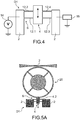
- the detection means use all or part of the beams 12.1 to 12.4 formed from a piezoresistive material.
- the beams are for example made of silicon.
- the four beams are made of piezoresistive material and participate in the vibration of the platform.
- only the beams 12.1 and 12.3 or 12.2 and 12.4 are made of piezoresistive material.
- the detection means also comprise a source 14 of constant voltage V and means 16 for measuring the output current I.
- the constant voltage source is for example connected to the support to which the beams 12.1, 12.2 are anchored, and the means 16 for measuring the output current are connected to the support to which the beams 12.3, 12.4 are anchored.
- the current flowing through the structure is at frequency f 0/2 because of the thermal actuation, so that the output current has terms at three different frequencies: at that of the actuation frequency, and two additional components that appear only when the structure is in resonance. These components can be measured using heterodyne detection methods or a spectra analyzer.
- the resonant frequency is modified, causing a variation of R and a variation of I.
- R the resonant frequency
- piezoelectric detection means has the advantage of being of reduced size, which makes it possible to optimize the capture surface on the same chip.
- detection means in which the detection means are of the optical type, suitable for a device having a mode in the plane.
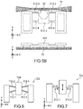
- the detection means comprise an optical device comprising at least one waveguide 18 and an optical resonator 20 in the form of a ring, which is coupled to the waveguide 18 by an evanescent coupling.
- the optical device also comprises a light source, for example a laser (not shown) optically coupled to the waveguide 18.
- the optical ring 20 is fixed to the support 2 and located near the platform, so that at least one edge of the platform is in the evanescent field of the ring and that the displacement of the ring influences the evanescent field .
- the distance between the ring and an edge of the platform is of the order of 100 nm.
- the orientation of the ring relative to the platform is such that when the platform is put into vibration, the distance between the ring and the platform varies, while remaining within the perimeter of the evanescent field.
- a light wave of constant power is injected into the optical ring.
- the displacement of the platform near the ring modifies the optical properties of the ring, including its optical resonance frequency, the light power recovered by the waveguide 18 is then modulated due to the influence of the displacement of the platform on the optical properties of the ring.
- spectrometric means it is possible to obtain an output power of the light beam proportional to the displacement of the platform.
- the optical detection means comprise an external laser and interferometric detection means.
- the actuating means 10 for example optical or electrostatic, are activated so as to set in vibration, at one of its resonance frequencies, the platform 4 along the Y direction, the beams 12.2 to 12.4 are deformed in bending as this is represented on the figure 3 . Due to the dimensions of the beams and of the platform, the deformations of the beams have little or no mechanical effect on the platform, the latter being little or not deformed.
- the detection means for example optical or piezoelectric, detect the vibratory displacement of the platform.
- the particle and platform assembly When a particle is deposited on the platform, the particle and platform assembly has a resonant frequency different from that of the platform alone.
- the detection means detect the modified vibratory displacement of the platform carrying the particle.
- the variation in resonant frequency is then processed and makes it possible to go back to the mass of the deposited particle.
- the detection device is integrated into a detection system comprising means for processing the measurement signals supplied by the detection device, in order to provide the mass of the deposited particle, or even the designation of the deposited particle.
- the influence on the resonant frequency is the same or almost the same.
- a single resonance mode is sufficient to detect a particle whatever its location on the platform.
- the frequency shift due to the deposit of a particle on the platform varies little as a function of the location of the deposit.
- the surface of the platform can be very large and can be adjusted according to the applications.
- the resonant frequency of the platform is easily adjusted by choosing the dimensioning of the beams of the suspension means, regardless of the shape of the platform.
- the beams are parallel to each other.
- the suspension beams of the platform 104 can be oriented so that their longitudinal axes intersect.
- the beams 112.1 and 112.2 and the beams 112.3 and 112.4 are arranged symmetrically with respect to the Y axis.
- the beams 212.1, 212.2 may have a shape other than a rectilinear shape, for example they may have the shape of a spring, such as this is visible in device D3 shown on figure 7 .
- the length to be taken into account in the inequalities l ⁇ 10 ⁇ L and l ⁇ 10 ⁇ e is the length of the developed spring.
- the beams can have a cross section of variable area continuously or by portion.
- the inequalities (I) consider the maximum values of L and e
- the inequalities (II) consider the minimum value of e.
- the beams may not all have the same length, as shown in the figure 8A , on which the beams 312.1 and 312.3 of the device D4 are shorter than the beams 312.2 and 312.4.
- the platform 404 comprises recesses 414 in the X direction, for each of the beams and at the bottom of which one end of the beams 412.1 to 412.4 is anchored.
- one edge of the platform 4 "has a recess 4.5 of a shape corresponding to the optical disc to house the latter.
- the optical disc 20 is partially bordered by an arc-shaped edge of the platform.
- the number of beams is not limited to four, it can be envisaged to provide six beams or more.
- the beams are distributed symmetrically with respect to the direction of movement to obtain a uniform movement of the platform.
- the platform is excited so that it has an out-of-plane movement, ie along the Z axis, as shown schematically on the diagram. figure 9 .
- the mobile structure comprising the platform and the beams is dimensioned so that during the displacement of the platform and the deformation of the beams, the platform is not or only slightly deformed under the action of the beams.
- the platform moves along the Z axis without deforming in bending.
- the actuating means capable of setting the platform 404 in motion along the Z direction may be the same as those implemented to generate a displacement in the plane. In the case of a piezoelectric shaker, this is such that it moves the support in the Z direction.
- the detection means comprise an optical ring arranged under the platform and a waveguide 18 in the plane of the ring.
- the displacement of the platform in the Z direction, near the ring modifies the optical properties of the ring, including its optical resonance frequency.
- the light power recovered by the waveguide 18 is then modulated due to the influence of the displacement of the platform on the optical properties of the ring.
- the platform advantageously protects the optical ring from the deposit of mass, which avoids additional effects of mass on the optical response.
- the detection means capable of detecting the displacement of the platform can be similar to those implemented for the detection of displacements in the plane.
- the platform 604 can be excited according to transverse modes in the plane relative to the support 602, ie modes in which the direction of movement corresponds to the longitudinal direction of the beams 612.1 to 612.4, ie according to the direction in the representation of figure 10 .
- the beams are preferably in the form of a spring.
- the mass spectrometer comprises a vacuum chamber 700 supplied by a source of analyte 702, ionization means 704 of the analyte at the inlet of the chamber 700, focusing means 706 of the ionized analyte downstream of the means. ionization sensor and a mass sensor 708 according to the invention downstream of the focusing means.
- the sensor is connected to means for measuring and processing the signal 710 emitted by the sensor 708.
- the detection device can be produced by microelectronic techniques.
- silicon on Insulator substrate comprising a silicon substrate 702, a layer of SiO 2 704 and a layer of silicon 706. This substrate is shown seen from the side. and seen from above on the figure 12A .
- the layer 706 is structured, for example by photolithography and etching, so as to form the mobile structure in the layer 706 having the appropriate dimensions of the beams and of the platform to ensure a low deformation, or even an absence of deformation of the platform during its vibration.
- the mobile structure is released, for example by anisotropic wet etching of SiO 2 704.
- the mobile structure can be made from another material, such as gallium, silicon nitride or aluminum.
- the platform and the beams are in the same material. In another example, they are made from different materials, for example having different mechanical properties.
- the platform can be made from a material having greater stiffness and the beams having lower stiffness, for example by choosing a material with a higher Young's modulus for the platform than for the beams. For example, we can choose in the case of a device with displacement in the plane Epoutre x L ⁇ Eplateforme x b, and in the case of a device with displacement outside the plane Epoutre x e ⁇ Eplateforme x E
- the minimum size of the detection device depends on the manufacturing process and its ability to produce beams of small section. For example, if the manufacturing technology limits the minimum dimension of an element to 50nm, the smallest section of the beams can be 50nm x50nm, as a result, the length of the beams is at least 500nm, and the platform has at least a minimum dimension of 500nm in the direction of movement.
- the mobile structure is released, for example by anisotropic wet etching of SiO 2 704.
- the mobile structure is released, for example by anisotropic wet etching of SiO 2 704.
Landscapes
- Physics & Mathematics (AREA)
- Chemical & Material Sciences (AREA)
- General Physics & Mathematics (AREA)
- Analytical Chemistry (AREA)
- Life Sciences & Earth Sciences (AREA)
- Health & Medical Sciences (AREA)
- Biochemistry (AREA)
- General Health & Medical Sciences (AREA)
- Immunology (AREA)
- Pathology (AREA)
- Dispersion Chemistry (AREA)
- Acoustics & Sound (AREA)
- Micromachines (AREA)
- Measurement Of Mechanical Vibrations Or Ultrasonic Waves (AREA)
- Investigating Or Analyzing Materials By The Use Of Ultrasonic Waves (AREA)
Claims (12)
- Vorrichtung zur Detektion von Partikeln, umfassend einen Träger und wenigstens eine bezüglich des Trägers (2) bewegliche Struktur, wobei die bewegliche Struktur eine Plattform (4) umfasst, von der wenigstens eine Fläche dazu ausgelegt ist, das oder die zu detektierende Partikel zu empfangen, Mittel (6) zur Aufhängung der Plattform (4) derart, dass die Plattform (4) bezüglich des Trägers (2) in Vibration versetzt werden kann, Mittel (8) zum Invibrationversetzen der Plattform (4) bei wenigstens einer ihrer Resonanzfrequenzen, Mittel (10) zur Detektion der Verlagerung der Plattform (4) in einer gegebenen Richtung, wobei die Aufhängungsmittel (6) wenigstens zwei Balken (12.1, 12.2, 12.3, 12.4) umfassen, die dazu konfiguriert sind, sich zu verformen, wenn die Plattform (4) in Vibration versetzt wird, wobei jeder Balken (12.1, 12.2, 12.3, 12.4) eine Länge l, eine Breite L und eine Dicke e aufweist, und die Plattform (4) eine Abmessung in der Verlagerungsrichtung der Plattform aufweist, dadurch gekennzeichnet, dass- die Abmessung jedes Balkens in der gegebenen Verlagerungsrichtung der Plattform (4) wenigstens 10 Mal kleiner ist als die Abmessung der Plattform (4) in der gegebenen Verlagerungsrichtung, und- im Fall einer Detektionsvorrichtung mit einem Modus in der Ebene, l ≥ 10 x L, und im Fall einer Detektionsvorrichtung mit einem Modus außerhalb der Ebene l ≥ 10 x e,
derart, dass dann, wenn die Plattform (44) in Vibration versetzt wird, diese durch die Wirkung der Balken nicht oder wenig verformt wird. - Detektionsvorrichtung nach Anspruch 1, bei der die Aufhängungsmittel (6) wenigstens einen ersten Balken und einen zweiten Balken umfasst, wobei der erste und der zweite Balken symmetrisch mit Bezug zu der Verlagerungsrichtung angeordnet sind.
- Detektionsvorrichtung nach Anspruch 1 oder 2, bei der die Betätigungsmittel (8) außerhalb der beweglichen Struktur sind.
- Detektionsvorrichtung nach Anspruch 1 oder 2, bei der die Betätigungsmittel (8) direkt auf die Plattform wirken.
- Detektionsvorrichtung nach Anspruch 4, bei der die Betätigungsmittel (8) optische Mittel sind, die eine Gradientenkraft mit der Resonanzfrequenz auf die Plattform ausüben, oder elektrostatische Mittel, die eine elektrostatische Kraft mit der Resonanzfrequenz auf die Plattform ausüben.
- Detektionsvorrichtung nach einem der Ansprüche 1 bis 5, bei der wenigstens zwei Balken aus einem piezoresistiven Material sind, beispielsweise aus Silizium, und bei der die Detektionsmittel eine Gleichspannungsquelle (14) umfassen, die dazu ausgelegt ist, eine Potentialdifferenz an die Balken anzulegen, und Mittel (16) zum Messen eines Stroms am Ausgang der Balken.
- Detektionsvorrichtung nach einem der Ansprüche 1 bis 6, bei der die Detektionsmittel einen optischen Resonator (20) umfassen, der in der Nähe der Plattform (4) derart angeordnet ist, dass die Verlagerung der Plattform (4) ein evaneszentes Feld des optischen Resonators (20) verändert, und einen Wellenleiter (18), der dazu ausgelegt ist, einen Lichtstrahl in den optischen Resonator (20) zu injizieren und den Lichtstrahl einzusammeln, der aus dem optischen Resonator (20) austritt.
- Detektionsvorrichtung nach einem der Ansprüche 1 bis 5 und 7, umfassend mehrere bewegliche Strukturen, die um den optischen Resonator herum angeordnet sind, wobei die Verlagerung jeder Plattform das evaneszente Feld des optischen Resonators verändert.
- Detektionsvorrichtung nach einem der Ansprüche 1 bis 8, bei der die Plattform (4) rechteckig ist, wobei zwei Balken (12.1, 12.2) an einer ersten Seite mit größerer Länge (4.1) der Plattform (4) befestigt sind, und orthogonal zu der ersten Seite (4.1) zwei andere Balken (12.3, 12.4) an einer zweiten Seite mit größerer Länge (4.1) der Plattform (4) orthogonal zu der zweiten Seite (4.1) befestigt sind, und wobei die Balken (12.1, 12.2, 12.3, 12.4) gerade und zueinander parallel sind.
- Detektionsvorrichtung nach Anspruch 9, bei der die Balken (12.1, 12.2, 12.3, 12.4) an der ersten und der zweiten Seite (4.1) mit größerer Länge in einem Abstand von den Längsenden der ersten und der zweiten Seite mit größerer Länge (4.1) befestigt sind.
- Detektionsvorrichtung nach einem der Ansprüche 1 bis 10, bei der die Balken aus einem Material hergestellt sind, das von jenem der Plattform verschieden ist.
- Massenspektrometer, umfassend Mittel zum Ionisieren eines Analyten, Mittel zum Fokussieren des ionisierten Analyten sowie wenigstens eine Detektionsvorrichtung nach einem der Ansprüche 1 bis 11, die stromabwärts der Fokussierungsmittel angeordnet ist.
Applications Claiming Priority (1)
| Application Number | Priority Date | Filing Date | Title |
|---|---|---|---|
| FR1850025A FR3076290B1 (fr) | 2018-01-03 | 2018-01-03 | Dispositif de detection micro ou nanomecanique de particules |
Publications (2)
| Publication Number | Publication Date |
|---|---|
| EP3509214A1 EP3509214A1 (de) | 2019-07-10 |
| EP3509214B1 true EP3509214B1 (de) | 2020-11-18 |
Family
ID=62167451
Family Applications (1)
| Application Number | Title | Priority Date | Filing Date |
|---|---|---|---|
| EP19150014.9A Active EP3509214B1 (de) | 2018-01-03 | 2019-01-02 | Mikro- oder nanomechanische vorrichtung zur detektion von partikeln |
Country Status (4)
| Country | Link |
|---|---|
| US (1) | US10794813B2 (de) |
| EP (1) | EP3509214B1 (de) |
| CN (1) | CN109994364B (de) |
| FR (1) | FR3076290B1 (de) |
Families Citing this family (8)
| Publication number | Priority date | Publication date | Assignee | Title |
|---|---|---|---|---|
| TWI647435B (zh) * | 2018-01-19 | 2019-01-11 | 國立清華大學 | 熱致動振盪式懸浮微粒感測裝置及懸浮微粒感測方法 |
| CN110361116B (zh) * | 2019-08-14 | 2020-11-20 | 合肥工业大学 | 一种四压力膜结构差动型石英梁谐振压力传感器 |
| CN112782426B (zh) * | 2019-11-07 | 2026-02-17 | 霍尼韦尔国际公司 | 包括一个或多个具有附加质量块的机械梁的谐振器 |
| CN113486557B (zh) * | 2021-07-12 | 2023-07-21 | 交通运输部天津水运工程科学研究所 | 一种基于内外模式的二、三维数学模型耦合模拟方法 |
| US12549151B2 (en) * | 2022-04-12 | 2026-02-10 | Murata Manufacturing Co., Ltd. | Transversely-excited film bulk acoustic resonator with thick dielectric layer for improved coupling |
| FR3143141B1 (fr) * | 2022-12-08 | 2024-10-25 | Commissariat Energie Atomique | Dispositif photonique isolé mécaniquement d'un substrat |
| FR3154806A1 (fr) * | 2023-10-30 | 2025-05-02 | Commissariat A L'energie Atomique Et Aux Energies Alternatives | Système opto-mécanique de transduction pour la spectrométrie photo-acoustique |
| FR3154721A1 (fr) * | 2023-10-30 | 2025-05-02 | Commissariat A L'energie Atomique Et Aux Energies Alternatives | Système opto-mécanique de transduction à détection améliorée |
Family Cites Families (9)
| Publication number | Priority date | Publication date | Assignee | Title |
|---|---|---|---|---|
| US5208458A (en) * | 1991-11-05 | 1993-05-04 | Georgia Tech Research Corporation | Interface device to couple gel electrophoresis with mass spectrometry using sample disruption |
| US6249073B1 (en) * | 1999-01-14 | 2001-06-19 | The Regents Of The University Of Michigan | Device including a micromechanical resonator having an operating frequency and method of extending same |
| JP4840058B2 (ja) * | 2006-09-29 | 2011-12-21 | ブラザー工業株式会社 | 光走査装置及びそれを備えた画像表示装置並びに網膜走査型画像表示装置、及び光走査素子の駆動方法 |
| US8390912B2 (en) * | 2007-01-10 | 2013-03-05 | Seiko Epson Corporation | Actuator, optical scanner and image forming device |
| JP5589459B2 (ja) * | 2010-03-15 | 2014-09-17 | セイコーエプソン株式会社 | 光フィルター及び光フィルターモジュール並びに分析機器及び光機器 |
| CN102621064A (zh) * | 2012-03-16 | 2012-08-01 | 无锡正慈机电科技有限公司 | 一种减振平台及基于该减振平台的光学检测系统 |
| US9846060B2 (en) * | 2013-03-28 | 2017-12-19 | Frauhofer-Gesellschaft Zur Foerderung Der Angewandten Forschung E.V. | Optical sensor arrangement and method for measuring an observable |
| FR3041761B1 (fr) * | 2015-09-24 | 2019-05-03 | Commissariat A L'energie Atomique Et Aux Energies Alternatives | Capteur physique opto-mecanique a sensibilite amelioree |
| CN106525669B (zh) * | 2016-10-28 | 2018-10-26 | 山东理工大学 | 光动量激励纳米梁纳微颗粒质量测量装置与方法 |
-
2018
- 2018-01-03 FR FR1850025A patent/FR3076290B1/fr not_active Expired - Fee Related
-
2019
- 2019-01-02 CN CN201910003107.4A patent/CN109994364B/zh active Active
- 2019-01-02 EP EP19150014.9A patent/EP3509214B1/de active Active
- 2019-01-02 US US16/237,817 patent/US10794813B2/en active Active
Also Published As
| Publication number | Publication date |
|---|---|
| FR3076290B1 (fr) | 2020-02-07 |
| CN109994364B (zh) | 2024-03-08 |
| CN109994364A (zh) | 2019-07-09 |
| FR3076290A1 (fr) | 2019-07-05 |
| EP3509214A1 (de) | 2019-07-10 |
| US20190204205A1 (en) | 2019-07-04 |
| US10794813B2 (en) | 2020-10-06 |
Similar Documents
| Publication | Publication Date | Title |
|---|---|---|
| EP3509214B1 (de) | Mikro- oder nanomechanische vorrichtung zur detektion von partikeln | |
| EP2930506B1 (de) | Erkennungsvorrichtung mit akustischem resonator für differentialanwendungen vom typ helmholtz-resonator | |
| EP2866000B1 (de) | Optomechanische Vorrichtung zum Betätigen und/oder Erkennen einer Bewegung eines mechanischen Elements, insbesondere für die gravimetrische Erfassung | |
| EP2485243B1 (de) | Mikro-Reflektron für Flugzeit-Massenspektrometer | |
| EP2904384B1 (de) | Messsystem mit einem nano-elektromechanischen resonatoren-array | |
| EP3538479B1 (de) | Vorrichtung zur übertragung einer bewegung und einer kraft zwischen zwei voneinander isolierten zonen | |
| EP2880438B1 (de) | Gasanalysevorrichtung mit einem einen mikro-reflektron aufweisenden massenspektrometer | |
| EP3185011A1 (de) | Gassensor mit verbesserter selektivität und kompaktheit | |
| FR2995690A1 (fr) | Capteur de flux thermique a element vibrant et capteur de gaz comportant au moins un tel capteur | |
| WO2012038524A1 (fr) | Bolometre a detection frequentielle | |
| FR2792722A1 (fr) | Capteur gyroscopique et appareil de mesure de rotation en comportant application | |
| EP0915323A1 (de) | Mikromechanischer Schwingkreisel | |
| EP2574885B1 (de) | Verfahren und vorrichtung zum bestimmen der masse von partikeln in einem fluid | |
| FR3052765A1 (fr) | Dispositif microelectromecanique et/ou nanoelectromecanique a deplacement hors-plan comportant des moyens capacitifs a variation de surface | |
| EP2949621A1 (de) | Kapazitive mikro- und/ oder nanoelektronische vorrichtung mit erhöhter kompaktheit | |
| EP2279557B1 (de) | N/mems matrix resonator filter | |
| WO2020008157A2 (fr) | Gyrometre micromecanique resonant performant a encombrement reduit | |
| EP2018347A1 (de) | Piezoelektrisches mikrosystem zur aktiven schwingungsisolierung von schwingungsempfindlichen komponenten | |
| FR2860865A1 (fr) | Gyrometre micromecanique infertiel a diapason | |
| FR3162278A1 (fr) | Dispositif de spectroscopie photoacoustique | |
| EP4549928A1 (de) | Optomechanisches wandlersystem für die photoakustische spektrometrie | |
| EP4549927A1 (de) | Optomechanisches transduktionssystem mit verbesserter detektion | |
| FR3157535A1 (fr) | Cellule de mesure pour la mesure de la force surfacique exercée par un flux de particules | |
| FR3055011A1 (fr) | Capteur micromecanique avec transduction optique |
Legal Events
| Date | Code | Title | Description |
|---|---|---|---|
| PUAI | Public reference made under article 153(3) epc to a published international application that has entered the european phase |
Free format text: ORIGINAL CODE: 0009012 |
|
| STAA | Information on the status of an ep patent application or granted ep patent |
Free format text: STATUS: REQUEST FOR EXAMINATION WAS MADE |
|
| 17P | Request for examination filed |
Effective date: 20190102 |
|
| AK | Designated contracting states |
Kind code of ref document: A1 Designated state(s): AL AT BE BG CH CY CZ DE DK EE ES FI FR GB GR HR HU IE IS IT LI LT LU LV MC MK MT NL NO PL PT RO RS SE SI SK SM TR |
|
| AX | Request for extension of the european patent |
Extension state: BA ME |
|
| REG | Reference to a national code |
Ref country code: DE Ref legal event code: R079 Ref document number: 602019001293 Country of ref document: DE Free format text: PREVIOUS MAIN CLASS: H03H0009020000 Ipc: H01J0049260000 |
|
| GRAP | Despatch of communication of intention to grant a patent |
Free format text: ORIGINAL CODE: EPIDOSNIGR1 |
|
| STAA | Information on the status of an ep patent application or granted ep patent |
Free format text: STATUS: GRANT OF PATENT IS INTENDED |
|
| RIC1 | Information provided on ipc code assigned before grant |
Ipc: G01H 9/00 20060101ALN20200515BHEP Ipc: H03H 9/02 20060101ALI20200515BHEP Ipc: G01H 11/08 20060101ALN20200515BHEP Ipc: H01J 49/26 20060101AFI20200515BHEP Ipc: H03H 9/24 20060101ALI20200515BHEP Ipc: G01D 5/26 20060101ALN20200515BHEP |
|
| INTG | Intention to grant announced |
Effective date: 20200608 |
|
| GRAS | Grant fee paid |
Free format text: ORIGINAL CODE: EPIDOSNIGR3 |
|
| GRAA | (expected) grant |
Free format text: ORIGINAL CODE: 0009210 |
|
| STAA | Information on the status of an ep patent application or granted ep patent |
Free format text: STATUS: THE PATENT HAS BEEN GRANTED |
|
| AK | Designated contracting states |
Kind code of ref document: B1 Designated state(s): AL AT BE BG CH CY CZ DE DK EE ES FI FR GB GR HR HU IE IS IT LI LT LU LV MC MK MT NL NO PL PT RO RS SE SI SK SM TR |
|
| REG | Reference to a national code |
Ref country code: GB Ref legal event code: FG4D Free format text: NOT ENGLISH |
|
| REG | Reference to a national code |
Ref country code: CH Ref legal event code: EP |
|
| REG | Reference to a national code |
Ref country code: IE Ref legal event code: FG4D Free format text: LANGUAGE OF EP DOCUMENT: FRENCH |
|
| REG | Reference to a national code |
Ref country code: DE Ref legal event code: R096 Ref document number: 602019001293 Country of ref document: DE |
|
| REG | Reference to a national code |
Ref country code: AT Ref legal event code: REF Ref document number: 1336679 Country of ref document: AT Kind code of ref document: T Effective date: 20201215 |
|
| REG | Reference to a national code |
Ref country code: AT Ref legal event code: MK05 Ref document number: 1336679 Country of ref document: AT Kind code of ref document: T Effective date: 20201118 |
|
| REG | Reference to a national code |
Ref country code: NL Ref legal event code: MP Effective date: 20201118 |
|
| PG25 | Lapsed in a contracting state [announced via postgrant information from national office to epo] |
Ref country code: NO Free format text: LAPSE BECAUSE OF FAILURE TO SUBMIT A TRANSLATION OF THE DESCRIPTION OR TO PAY THE FEE WITHIN THE PRESCRIBED TIME-LIMIT Effective date: 20210218 Ref country code: PT Free format text: LAPSE BECAUSE OF FAILURE TO SUBMIT A TRANSLATION OF THE DESCRIPTION OR TO PAY THE FEE WITHIN THE PRESCRIBED TIME-LIMIT Effective date: 20210318 Ref country code: RS Free format text: LAPSE BECAUSE OF FAILURE TO SUBMIT A TRANSLATION OF THE DESCRIPTION OR TO PAY THE FEE WITHIN THE PRESCRIBED TIME-LIMIT Effective date: 20201118 Ref country code: FI Free format text: LAPSE BECAUSE OF FAILURE TO SUBMIT A TRANSLATION OF THE DESCRIPTION OR TO PAY THE FEE WITHIN THE PRESCRIBED TIME-LIMIT Effective date: 20201118 |
|
| PG25 | Lapsed in a contracting state [announced via postgrant information from national office to epo] |
Ref country code: AT Free format text: LAPSE BECAUSE OF FAILURE TO SUBMIT A TRANSLATION OF THE DESCRIPTION OR TO PAY THE FEE WITHIN THE PRESCRIBED TIME-LIMIT Effective date: 20201118 Ref country code: BG Free format text: LAPSE BECAUSE OF FAILURE TO SUBMIT A TRANSLATION OF THE DESCRIPTION OR TO PAY THE FEE WITHIN THE PRESCRIBED TIME-LIMIT Effective date: 20210218 Ref country code: LV Free format text: LAPSE BECAUSE OF FAILURE TO SUBMIT A TRANSLATION OF THE DESCRIPTION OR TO PAY THE FEE WITHIN THE PRESCRIBED TIME-LIMIT Effective date: 20201118 Ref country code: IS Free format text: LAPSE BECAUSE OF FAILURE TO SUBMIT A TRANSLATION OF THE DESCRIPTION OR TO PAY THE FEE WITHIN THE PRESCRIBED TIME-LIMIT Effective date: 20210318 Ref country code: PL Free format text: LAPSE BECAUSE OF FAILURE TO SUBMIT A TRANSLATION OF THE DESCRIPTION OR TO PAY THE FEE WITHIN THE PRESCRIBED TIME-LIMIT Effective date: 20201118 Ref country code: SE Free format text: LAPSE BECAUSE OF FAILURE TO SUBMIT A TRANSLATION OF THE DESCRIPTION OR TO PAY THE FEE WITHIN THE PRESCRIBED TIME-LIMIT Effective date: 20201118 |
|
| REG | Reference to a national code |
Ref country code: LT Ref legal event code: MG9D |
|
| PG25 | Lapsed in a contracting state [announced via postgrant information from national office to epo] |
Ref country code: HR Free format text: LAPSE BECAUSE OF FAILURE TO SUBMIT A TRANSLATION OF THE DESCRIPTION OR TO PAY THE FEE WITHIN THE PRESCRIBED TIME-LIMIT Effective date: 20201118 |
|
| PG25 | Lapsed in a contracting state [announced via postgrant information from national office to epo] |
Ref country code: RO Free format text: LAPSE BECAUSE OF FAILURE TO SUBMIT A TRANSLATION OF THE DESCRIPTION OR TO PAY THE FEE WITHIN THE PRESCRIBED TIME-LIMIT Effective date: 20201118 Ref country code: LT Free format text: LAPSE BECAUSE OF FAILURE TO SUBMIT A TRANSLATION OF THE DESCRIPTION OR TO PAY THE FEE WITHIN THE PRESCRIBED TIME-LIMIT Effective date: 20201118 Ref country code: EE Free format text: LAPSE BECAUSE OF FAILURE TO SUBMIT A TRANSLATION OF THE DESCRIPTION OR TO PAY THE FEE WITHIN THE PRESCRIBED TIME-LIMIT Effective date: 20201118 Ref country code: CZ Free format text: LAPSE BECAUSE OF FAILURE TO SUBMIT A TRANSLATION OF THE DESCRIPTION OR TO PAY THE FEE WITHIN THE PRESCRIBED TIME-LIMIT Effective date: 20201118 Ref country code: SM Free format text: LAPSE BECAUSE OF FAILURE TO SUBMIT A TRANSLATION OF THE DESCRIPTION OR TO PAY THE FEE WITHIN THE PRESCRIBED TIME-LIMIT Effective date: 20201118 Ref country code: SK Free format text: LAPSE BECAUSE OF FAILURE TO SUBMIT A TRANSLATION OF THE DESCRIPTION OR TO PAY THE FEE WITHIN THE PRESCRIBED TIME-LIMIT Effective date: 20201118 |
|
| REG | Reference to a national code |
Ref country code: DE Ref legal event code: R097 Ref document number: 602019001293 Country of ref document: DE |
|
| PG25 | Lapsed in a contracting state [announced via postgrant information from national office to epo] |
Ref country code: DK Free format text: LAPSE BECAUSE OF FAILURE TO SUBMIT A TRANSLATION OF THE DESCRIPTION OR TO PAY THE FEE WITHIN THE PRESCRIBED TIME-LIMIT Effective date: 20201118 Ref country code: MC Free format text: LAPSE BECAUSE OF FAILURE TO SUBMIT A TRANSLATION OF THE DESCRIPTION OR TO PAY THE FEE WITHIN THE PRESCRIBED TIME-LIMIT Effective date: 20201118 |
|
| PLBE | No opposition filed within time limit |
Free format text: ORIGINAL CODE: 0009261 |
|
| STAA | Information on the status of an ep patent application or granted ep patent |
Free format text: STATUS: NO OPPOSITION FILED WITHIN TIME LIMIT |
|
| PG25 | Lapsed in a contracting state [announced via postgrant information from national office to epo] |
Ref country code: LU Free format text: LAPSE BECAUSE OF NON-PAYMENT OF DUE FEES Effective date: 20210102 |
|
| REG | Reference to a national code |
Ref country code: BE Ref legal event code: MM Effective date: 20210131 |
|
| 26N | No opposition filed |
Effective date: 20210819 |
|
| PG25 | Lapsed in a contracting state [announced via postgrant information from national office to epo] |
Ref country code: IT Free format text: LAPSE BECAUSE OF FAILURE TO SUBMIT A TRANSLATION OF THE DESCRIPTION OR TO PAY THE FEE WITHIN THE PRESCRIBED TIME-LIMIT Effective date: 20201118 Ref country code: NL Free format text: LAPSE BECAUSE OF FAILURE TO SUBMIT A TRANSLATION OF THE DESCRIPTION OR TO PAY THE FEE WITHIN THE PRESCRIBED TIME-LIMIT Effective date: 20201118 Ref country code: AL Free format text: LAPSE BECAUSE OF FAILURE TO SUBMIT A TRANSLATION OF THE DESCRIPTION OR TO PAY THE FEE WITHIN THE PRESCRIBED TIME-LIMIT Effective date: 20201118 |
|
| PG25 | Lapsed in a contracting state [announced via postgrant information from national office to epo] |
Ref country code: SI Free format text: LAPSE BECAUSE OF FAILURE TO SUBMIT A TRANSLATION OF THE DESCRIPTION OR TO PAY THE FEE WITHIN THE PRESCRIBED TIME-LIMIT Effective date: 20201118 |
|
| PG25 | Lapsed in a contracting state [announced via postgrant information from national office to epo] |
Ref country code: ES Free format text: LAPSE BECAUSE OF FAILURE TO SUBMIT A TRANSLATION OF THE DESCRIPTION OR TO PAY THE FEE WITHIN THE PRESCRIBED TIME-LIMIT Effective date: 20201118 Ref country code: IE Free format text: LAPSE BECAUSE OF NON-PAYMENT OF DUE FEES Effective date: 20210102 |
|
| PG25 | Lapsed in a contracting state [announced via postgrant information from national office to epo] |
Ref country code: IS Free format text: LAPSE BECAUSE OF FAILURE TO SUBMIT A TRANSLATION OF THE DESCRIPTION OR TO PAY THE FEE WITHIN THE PRESCRIBED TIME-LIMIT Effective date: 20210318 |
|
| PG25 | Lapsed in a contracting state [announced via postgrant information from national office to epo] |
Ref country code: BE Free format text: LAPSE BECAUSE OF NON-PAYMENT OF DUE FEES Effective date: 20210131 |
|
| REG | Reference to a national code |
Ref country code: CH Ref legal event code: PL |
|
| PG25 | Lapsed in a contracting state [announced via postgrant information from national office to epo] |
Ref country code: LI Free format text: LAPSE BECAUSE OF NON-PAYMENT OF DUE FEES Effective date: 20220131 Ref country code: CH Free format text: LAPSE BECAUSE OF NON-PAYMENT OF DUE FEES Effective date: 20220131 |
|
| PG25 | Lapsed in a contracting state [announced via postgrant information from national office to epo] |
Ref country code: CY Free format text: LAPSE BECAUSE OF FAILURE TO SUBMIT A TRANSLATION OF THE DESCRIPTION OR TO PAY THE FEE WITHIN THE PRESCRIBED TIME-LIMIT Effective date: 20201118 |
|
| PG25 | Lapsed in a contracting state [announced via postgrant information from national office to epo] |
Ref country code: HU Free format text: LAPSE BECAUSE OF FAILURE TO SUBMIT A TRANSLATION OF THE DESCRIPTION OR TO PAY THE FEE WITHIN THE PRESCRIBED TIME-LIMIT; INVALID AB INITIO Effective date: 20190102 Ref country code: GR Free format text: LAPSE BECAUSE OF FAILURE TO SUBMIT A TRANSLATION OF THE DESCRIPTION OR TO PAY THE FEE WITHIN THE PRESCRIBED TIME-LIMIT Effective date: 20201118 |
|
| PG25 | Lapsed in a contracting state [announced via postgrant information from national office to epo] |
Ref country code: MK Free format text: LAPSE BECAUSE OF FAILURE TO SUBMIT A TRANSLATION OF THE DESCRIPTION OR TO PAY THE FEE WITHIN THE PRESCRIBED TIME-LIMIT Effective date: 20201118 |
|
| PG25 | Lapsed in a contracting state [announced via postgrant information from national office to epo] |
Ref country code: MT Free format text: LAPSE BECAUSE OF FAILURE TO SUBMIT A TRANSLATION OF THE DESCRIPTION OR TO PAY THE FEE WITHIN THE PRESCRIBED TIME-LIMIT Effective date: 20201118 |
|
| PG25 | Lapsed in a contracting state [announced via postgrant information from national office to epo] |
Ref country code: TR Free format text: LAPSE BECAUSE OF FAILURE TO SUBMIT A TRANSLATION OF THE DESCRIPTION OR TO PAY THE FEE WITHIN THE PRESCRIBED TIME-LIMIT Effective date: 20201118 |
|
| PGFP | Annual fee paid to national office [announced via postgrant information from national office to epo] |
Ref country code: GB Payment date: 20260121 Year of fee payment: 8 |
|
| PGFP | Annual fee paid to national office [announced via postgrant information from national office to epo] |
Ref country code: DE Payment date: 20260120 Year of fee payment: 8 |
|
| PGFP | Annual fee paid to national office [announced via postgrant information from national office to epo] |
Ref country code: FR Payment date: 20260121 Year of fee payment: 8 |