EP4549928A1 - Optomechanisches wandlersystem für die photoakustische spektrometrie - Google Patents
Optomechanisches wandlersystem für die photoakustische spektrometrie Download PDFInfo
- Publication number
- EP4549928A1 EP4549928A1 EP24209344.1A EP24209344A EP4549928A1 EP 4549928 A1 EP4549928 A1 EP 4549928A1 EP 24209344 A EP24209344 A EP 24209344A EP 4549928 A1 EP4549928 A1 EP 4549928A1
- Authority
- EP
- European Patent Office
- Prior art keywords
- sensor element
- sensor
- mechanical
- junction
- optical detector
- Prior art date
- Legal status (The legal status is an assumption and is not a legal conclusion. Google has not performed a legal analysis and makes no representation as to the accuracy of the status listed.)
- Pending
Links
- 238000004867 photoacoustic spectroscopy Methods 0.000 title description 5
- 230000026683 transduction Effects 0.000 title description 2
- 238000010361 transduction Methods 0.000 title description 2
- 230000003287 optical effect Effects 0.000 claims abstract description 74
- 230000005855 radiation Effects 0.000 claims abstract description 31
- 238000006073 displacement reaction Methods 0.000 claims abstract description 5
- 230000010363 phase shift Effects 0.000 claims abstract description 3
- 230000002463 transducing effect Effects 0.000 claims abstract description 3
- 238000001514 detection method Methods 0.000 claims description 33
- 239000000758 substrate Substances 0.000 claims description 24
- 230000005284 excitation Effects 0.000 claims description 14
- 238000004873 anchoring Methods 0.000 claims description 7
- 239000007789 gas Substances 0.000 description 25
- 230000008878 coupling Effects 0.000 description 10
- 238000010168 coupling process Methods 0.000 description 10
- 238000005859 coupling reaction Methods 0.000 description 10
- 230000000694 effects Effects 0.000 description 6
- 238000010521 absorption reaction Methods 0.000 description 5
- 230000003993 interaction Effects 0.000 description 4
- 239000004038 photonic crystal Substances 0.000 description 4
- 230000035945 sensitivity Effects 0.000 description 3
- 239000007787 solid Substances 0.000 description 3
- 238000004458 analytical method Methods 0.000 description 2
- 239000000463 material Substances 0.000 description 2
- 238000000034 method Methods 0.000 description 2
- 229910052710 silicon Inorganic materials 0.000 description 2
- 239000010703 silicon Substances 0.000 description 2
- 239000000126 substance Substances 0.000 description 2
- OKTJSMMVPCPJKN-UHFFFAOYSA-N Carbon Chemical compound [C] OKTJSMMVPCPJKN-UHFFFAOYSA-N 0.000 description 1
- 230000003321 amplification Effects 0.000 description 1
- 230000000295 complement effect Effects 0.000 description 1
- 230000008602 contraction Effects 0.000 description 1
- 238000013016 damping Methods 0.000 description 1
- 230000001419 dependent effect Effects 0.000 description 1
- 235000021183 entrée Nutrition 0.000 description 1
- 238000000105 evaporative light scattering detection Methods 0.000 description 1
- 229910021389 graphene Inorganic materials 0.000 description 1
- 230000010354 integration Effects 0.000 description 1
- 238000004519 manufacturing process Methods 0.000 description 1
- 230000007246 mechanism Effects 0.000 description 1
- 239000012528 membrane Substances 0.000 description 1
- 238000004377 microelectronic Methods 0.000 description 1
- 230000004048 modification Effects 0.000 description 1
- 238000012986 modification Methods 0.000 description 1
- 238000003199 nucleic acid amplification method Methods 0.000 description 1
- 238000005457 optimization Methods 0.000 description 1
- 238000010895 photoacoustic effect Methods 0.000 description 1
- 229910021420 polycrystalline silicon Inorganic materials 0.000 description 1
- 229920005591 polysilicon Polymers 0.000 description 1
- 230000008707 rearrangement Effects 0.000 description 1
- 230000009467 reduction Effects 0.000 description 1
- 238000011896 sensitive detection Methods 0.000 description 1
- 230000003595 spectral effect Effects 0.000 description 1
- 239000002341 toxic gas Substances 0.000 description 1
Images

Classifications
-
- G—PHYSICS
- G01—MEASURING; TESTING
- G01N—INVESTIGATING OR ANALYSING MATERIALS BY DETERMINING THEIR CHEMICAL OR PHYSICAL PROPERTIES
- G01N29/00—Investigating or analysing materials by the use of ultrasonic, sonic or infrasonic waves; Visualisation of the interior of objects by transmitting ultrasonic or sonic waves through the object
- G01N29/02—Analysing fluids
- G01N29/036—Analysing fluids by measuring frequency or resonance of acoustic waves
-
- G—PHYSICS
- G01—MEASURING; TESTING
- G01N—INVESTIGATING OR ANALYSING MATERIALS BY DETERMINING THEIR CHEMICAL OR PHYSICAL PROPERTIES
- G01N21/00—Investigating or analysing materials by the use of optical means, i.e. using sub-millimetre waves, infrared, visible or ultraviolet light
- G01N21/17—Systems in which incident light is modified in accordance with the properties of the material investigated
- G01N21/1702—Systems in which incident light is modified in accordance with the properties of the material investigated with opto-acoustic detection, e.g. for gases or analysing solids
-
- G—PHYSICS
- G01—MEASURING; TESTING
- G01N—INVESTIGATING OR ANALYSING MATERIALS BY DETERMINING THEIR CHEMICAL OR PHYSICAL PROPERTIES
- G01N29/00—Investigating or analysing materials by the use of ultrasonic, sonic or infrasonic waves; Visualisation of the interior of objects by transmitting ultrasonic or sonic waves through the object
- G01N29/02—Analysing fluids
- G01N29/022—Fluid sensors based on microsensors, e.g. quartz crystal-microbalance [QCM], surface acoustic wave [SAW] devices, tuning forks, cantilevers, flexural plate wave [FPW] devices
-
- G—PHYSICS
- G01—MEASURING; TESTING
- G01N—INVESTIGATING OR ANALYSING MATERIALS BY DETERMINING THEIR CHEMICAL OR PHYSICAL PROPERTIES
- G01N29/00—Investigating or analysing materials by the use of ultrasonic, sonic or infrasonic waves; Visualisation of the interior of objects by transmitting ultrasonic or sonic waves through the object
- G01N29/22—Details, e.g. general constructional or apparatus details
- G01N29/222—Constructional or flow details for analysing fluids
-
- G—PHYSICS
- G01—MEASURING; TESTING
- G01N—INVESTIGATING OR ANALYSING MATERIALS BY DETERMINING THEIR CHEMICAL OR PHYSICAL PROPERTIES
- G01N29/00—Investigating or analysing materials by the use of ultrasonic, sonic or infrasonic waves; Visualisation of the interior of objects by transmitting ultrasonic or sonic waves through the object
- G01N29/22—Details, e.g. general constructional or apparatus details
- G01N29/24—Probes
- G01N29/2418—Probes using optoacoustic interaction with the material, e.g. laser radiation, photoacoustics
-
- G—PHYSICS
- G01—MEASURING; TESTING
- G01N—INVESTIGATING OR ANALYSING MATERIALS BY DETERMINING THEIR CHEMICAL OR PHYSICAL PROPERTIES
- G01N29/00—Investigating or analysing materials by the use of ultrasonic, sonic or infrasonic waves; Visualisation of the interior of objects by transmitting ultrasonic or sonic waves through the object
- G01N29/22—Details, e.g. general constructional or apparatus details
- G01N29/24—Probes
- G01N29/2462—Probes with waveguides, e.g. SAW devices
-
- G—PHYSICS
- G01—MEASURING; TESTING
- G01N—INVESTIGATING OR ANALYSING MATERIALS BY DETERMINING THEIR CHEMICAL OR PHYSICAL PROPERTIES
- G01N21/00—Investigating or analysing materials by the use of optical means, i.e. using sub-millimetre waves, infrared, visible or ultraviolet light
- G01N21/01—Arrangements or apparatus for facilitating the optical investigation
- G01N2021/0106—General arrangement of respective parts
- G01N2021/0112—Apparatus in one mechanical, optical or electronic block
-
- G—PHYSICS
- G01—MEASURING; TESTING
- G01N—INVESTIGATING OR ANALYSING MATERIALS BY DETERMINING THEIR CHEMICAL OR PHYSICAL PROPERTIES
- G01N21/00—Investigating or analysing materials by the use of optical means, i.e. using sub-millimetre waves, infrared, visible or ultraviolet light
- G01N21/17—Systems in which incident light is modified in accordance with the properties of the material investigated
- G01N21/1702—Systems in which incident light is modified in accordance with the properties of the material investigated with opto-acoustic detection, e.g. for gases or analysing solids
- G01N2021/1704—Systems in which incident light is modified in accordance with the properties of the material investigated with opto-acoustic detection, e.g. for gases or analysing solids in gases
-
- G—PHYSICS
- G01—MEASURING; TESTING
- G01N—INVESTIGATING OR ANALYSING MATERIALS BY DETERMINING THEIR CHEMICAL OR PHYSICAL PROPERTIES
- G01N2291/00—Indexing codes associated with group G01N29/00
- G01N2291/02—Indexing codes associated with the analysed material
- G01N2291/021—Gases
- G01N2291/0215—Mixtures of three or more gases, e.g. air
-
- G—PHYSICS
- G01—MEASURING; TESTING
- G01N—INVESTIGATING OR ANALYSING MATERIALS BY DETERMINING THEIR CHEMICAL OR PHYSICAL PROPERTIES
- G01N2291/00—Indexing codes associated with group G01N29/00
- G01N2291/02—Indexing codes associated with the analysed material
- G01N2291/028—Material parameters
- G01N2291/02809—Concentration of a compound, e.g. measured by a surface mass change
Definitions
- the present invention relates to optomechanical detection using resonant micromechanical and/or nanomechanical structures. It finds a particularly advantageous application in photoacoustic detection, in particular for gas detection. It can be used in particular for photoacoustic spectrometry.
- the heat emission due to a collision with another molecule causes, among other things, a phenomenon of expansion and contraction of the gas, which generates an acoustic wave.
- the amplitude of this wave is proportional to the concentration of the gas within the medium.
- the amplitude of this wave can be measured using various means, and in particular by a mechanical sensor coupled to capacitive detection means, such a system being commonly referred to as a resonant capacitive microelectromechanical system.
- a mechanical sensor coupled to capacitive detection means such a system being commonly referred to as a resonant capacitive microelectromechanical system.
- the results obtained in the prior art are not satisfactory. Indeed, to maximize the mechanical detection of the acoustic wave it is necessary to increase the reception surface of the wave at the level of the mechanical sensor. In doing so, the size of the system is increased, which is unfavorable in terms of optimization of the integration.
- the air located between the mechanical sensor and the electrode located opposite to allow capacitive detection is alternately sucked in and evacuated by the mechanical sensor during its vibration. This air constitutes a viscous damper for the mechanical sensor.
- This phenomenon commonly referred to by the English term “squeeze film effect” (which can be translated as "compressed gas
- An objective of the present invention is thus to propose an alternative to existing integrated systems that can be used for photoacoustic spectrometry. Preferably, this alternative guarantees more precise detection than existing integrated systems.
- the system is characterized in that the vibration of the sensor element modifies the evanescent field of the optical detector and in that the sensor element moves in a direction called the transverse direction substantially perpendicular to the longitudinal plane when it is vibrating.
- the detection of the amplitude of the acoustic wave resulting from the excitation of a gas is carried out using a mechano-optical transduction system.
- the system according to the invention thus makes it possible to overcome the constraints specific to capacitive detection mentioned in the introduction. In particular, it is easy to limit or even eliminate the squeeze film effect, which could not be avoided in the case of a capacitive detection system.
- the system thus allows precise detection of the concentration of a gas.
- the system also has, thanks to this, improved sensitivity compared to existing detection devices. It can detect very low gas concentrations, which is particularly advantageous in certain fields such as the detection of toxic gases.
- the present invention thus provides a precise and sensitive detection system, while remaining compact.
- the invention makes it possible to produce a spectrometer capable of detecting several gases simultaneously, using a single inlet (an inlet allowing the gas to enter the cavity) and a single outlet (at the detection means).
- the mechanical sensor is connected to a substrate, the substrate having an upper face extending mainly in a plane parallel to the longitudinal plane and located opposite the mechanical sensor, the substrate having an opening passing entirely through it in the transverse direction, the opening being located at least partially opposite the mechanical sensor in the transverse direction.
- the sensor element and the optical detector are arranged side by side in projection in the longitudinal plane.
- the sensor element and the optical detector are arranged opposite each other in the transverse direction.
- the mechanical sensor comprises a receiving element intended to receive the acoustic wave and to be set into vibration by the acoustic wave at the vibration frequency, the mechanical sensor being configured so that the receiving element sets the sensor element into vibration at the vibration frequency when it is set into vibration by the acoustic wave at the vibration frequency.
- the receiving element and the sensing element are connected by a junction, the junction being connected to a substrate.
- the sensor element comprises a plurality of cantilever beams extending from the junction.
- the receiving element, the junction and the sensor element are aligned in a first direction, and when the system is at rest, each of the beams has a first dimension L 115,X in the first direction and a second dimension L 115,Y in a second direction perpendicular to the first direction and parallel to the longitudinal plane, with L 115,X > 10* L115,Y , preferably L 115,X > 20*L 115,Y .
- L 115,X is between 20 ⁇ m and 100 ⁇ m.
- L 115,Y is between 100 nm and 500 nm.
- the receiving element, the junction and the sensor element are aligned in a first direction, and, when the system is at rest, the sensor element has a first dimension L 110,X in the first direction and a second dimension L 110,Y in a second direction perpendicular to the first direction and parallel to the longitudinal plane, with L 110,X ⁇ 10*L 110,Y , preferably L 110,X ⁇ 100*L 110,Y .
- the receiving element, the junction and the sensor element are aligned in a first direction, and, when the system is at rest, the sensor element has a first dimension L 110,X along the first direction and the receiving element has a first dimension L 120,X along the first direction, with L 110,X ⁇ 0.42*L 120,X .
- the senor comprises a second sensor element separated from the sensor element by the receiver element, the second sensor element and the receiver element being connected by a second junction, the second junction being connected to the substrate via anchor points, the second sensor element, the second junction, the receiver element, the junction and the sensor element being aligned along the first direction, the system having a plane of symmetry perpendicular to the first direction, and, when the system is at rest, the sensor element and the second sensor element each have a first dimension L 110,X along the first direction and the sensor has a first dimension L 100,X along the first direction, with: 2L 110,X /L 100,X ⁇ 0.46.
- L 100,X 2L 110,X +L 120,X .
- f anch 2L 110,X /L 100,X .
- This factor f anch is representative of the positioning of the junction and the second junction, which separate the receiving element from the sensor element and the second sensor element. It was observed that when f anch ⁇ 0.46, a significant displacement was obtained at the ends of the sensor elements. This makes it possible to maximize the effect of the vibration of the sensor elements on the evanescent field and therefore to improve the detection sensitivity.
- the sensor element is intended to receive the acoustic wave directly.
- the sensor element is connected to a substrate by at least one junction.
- This substrate advantageously does not vibrate when the system receives the acoustic wave.
- This substrate can be described as fixed.
- the optical detector comprises an optical resonator and the optical resonator is at least partly housed in the aperture.
- the second light source is a laser source and the excitation radiation is laser radiation having a main wavelength greater than 700 nm.
- the cavity further comprises a conduit configured to bring the acoustic wave towards the mechanical sensor.
- the conduit is also configured to amplify the acoustic wave. It thus has an acoustic resonator function.
- a direction substantially normal to a plane means a direction presenting an angle of 90 ⁇ 10° with respect to the plane.
- the elements composing the system 1 may be formed in the same substrate 10 or, for some, may have been deposited on this substrate 10. Certain elements may be formed during the same manufacturing steps and be made of the same material, for example silicon or polysilicon.
- the substrate 10 may for example comprise a support substrate 11, typically based on silicon.
- a buried oxide layer 12 and an active layer 13 may cover the support substrate 11, the buried oxide layer 12 being located between the support substrate 11 and the active layer 13.
- the various elements of the system 1 described above are advantageously formed in the active layer 13 by conventional microelectronic methods.
- the substrate 10 has an upper face 10a extending mainly along a plane called the longitudinal plane XY.
- the longitudinal plane XY is defined by a first direction X and a second direction Y perpendicular to each other.
- System 1 comprises a mechanical sensor 100 and an optical detector 200.
- the mechanical sensor 100 is intended to receive an acoustic wave 5 so as to be set into vibration by this acoustic wave 5 at a vibration frequency.
- the structural characteristics (dimensioning, materials, etc.) of the mechanical sensor 100 are such that the latter is capable of being set into vibration in a frequency range.
- the mechanical sensor 100 is capable of vibrating in a frequency range including a resonance frequency corresponding to a given gas.
- a person skilled in the art has perfect mastery of how to produce such a sensor so that it can vibrate at a precise frequency, or at least in a frequency range including this frequency, and preferably centered around this frequency.
- the mechanical sensor 100 can be designed so that it is capable of vibrating in a frequency range including a resonance frequency f CO2 or f NH3 , and preferably capable of vibrating at a frequency substantially equal to f CO2 or f NH3 , corresponding respectively to the frequencies of the acoustic waves emitted following the excitation of CO 2 and NH 3 .
- the vibration amplitude of the mechanical sensor 100 will then correspond to the concentration of CO 2 or NH 3 , respectively.
- the frequencies f CO2 or f NH3 are dependent on the thermal relaxation time of CO2 and NH3, respectively, when these gases are excited by the excitation radiation. These gases are given as examples, but it is understood that these explanations are valid for any gas. It is understood that, although the mechanical sensor 100 is sized to be able to vibrate at the resonance frequency corresponding to a given molecule, the effective vibration frequency of the mechanical sensor 100 may not be exactly this resonance frequency. The system 1 will still be functional.
- the mechanical sensor 100 comprises a sensor element 110 which, when the mechanical sensor 100 receives the acoustic wave 5, is set into vibration at the resonance frequency.
- the sensor element 110 can directly receive the acoustic wave 5 or be set into vibration via a separate region having received this acoustic wave 5 and forming part of the mechanical sensor 100.
- the sensor element 110 has an upper face 110a which, when the system 1 is at rest, extends mainly in the longitudinal plane XY. It is understood that the system 1 is at rest when it is not vibrating due to the reception of an acoustic wave 5. It is then stationary relative to the substrate 10.
- optical detector 200 The following paragraphs describe the optical detector 200.
- the optical detector 200 typically comprises a waveguide 210, conventionally linear, and an optical resonator 220, for example in the form of a ring - we then speak of an optical ring -, a disk or more generally a “race track” (which can be translated into French by the term “circuit”).
- the waveguide 210 and the optical resonator 220 are coupled by an evanescent coupling.
- the waveguide 210 comprises an input 211 and an output 212 between which, when the system is in operation, light radiation, typically laser radiation, called detection radiation, is diffused.
- the coupling between the waveguide 210 and the optical resonator 220 is such that at least a portion of the detection radiation is injected into the optical resonator 220 and then collected again by the waveguide 210.
- the vibration of the sensor element 110 in the vicinity of the optical resonator 220 causes a modification of the effective optical index of the latter and therefore disturbs the detection radiation passing through the optical resonator 220.
- the optical resonator 220 and the sensor element 110 are positioned so that at least a portion of the sensor element 110 is in the evanescent field. of the optical resonator 220.
- the distance between the sensor element 110 and the optical resonator 220 may for example be of the order of 100 nm.
- the relative arrangement of the optical resonator 220 and the sensor element 110 is such that when the sensor element 110 is vibrating, the distance between these two elements varies and the sensor element 110 remains in the evanescent field of the optical resonator 220.
- the optical detector 200 further comprises means for detecting the power of the light radiation at the output 212 of the waveguide 210. This power is proportional to the displacement of the sensor element 110. The analysis of the evolution of this power thus makes it possible to determine the amplitude of the vibration of the sensor element 110 and its evolutions, therefore the amplitude of the acoustic wave and therefore to determine the concentration of the gaseous species studied in the medium.
- the means for detecting the power of the light radiation may for example comprise a spectrometer, a photodetector such as a photodiode, or an external laser and interferometric detection means.
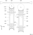
- a first embodiment of the system 1 will now be described with reference to the figures 1 And 2 . It is understood that on the Figure 2 two mechanical sensors 100 appear, but that the system 1 can perfectly include a single mechanical sensor 100, as on the Figure 1 , or more than two mechanical sensors 100.
- System 1 includes an optical detector 200 as described above.
- the mechanical sensor 100 comprises a receiving element 120 intended to receive the acoustic wave 5 and to be set into vibration by this acoustic wave 5 at the resonance frequency.
- This receiving element 120 is configured to, when it is vibrating, set the sensor element 110 into vibration.
- the receiving element 120 and the sensor element 110 are mechanically coupled.
- they may be connected by a junction 130 itself connected to the substrate 10.
- the position of the junction 130 defines the coupling between the receiving element 120 and the sensor element 110.
- the junction 130 may be a beam connected at each of its two ends to anchoring points 140.
- the beam preferably extends mainly along an axis parallel to the second direction Y, called the coupling axis.
- the beam has the capacity to deform in torsion around the coupling axis.
- the characteristics of the sensor element 110 such as for example its length L 110,X along the first direction X, those of the receiver element 120 and those of the junction 130 are such that these three elements 110, 120, 130 together form a mechanism for amplifying the mechanical vibration such that the amplitude of movement at the flank 110c of the sensor element 110 is greater than the amplitude of movement at the level of the main region 122 of the receiving element 120.
- Such amplification is notably permitted by a lever arm phenomenon.
- the receiving element 120 in order to allow good mechanical coupling between the receiving element 120 and the sensor element 110, the receiving element 120 preferably has an openwork region 121 adjacent to the junction 130 in projection in the longitudinal plane XY. More precisely, it is at the level of the openwork region 121 that the receiving element 120 is connected to the junction 130.
- the openwork region 121 preferably comprises a plurality of beams, each being fixed at one end to the junction 130.
- the receiving element 120 preferably comprises a main region 122 that is solid, i.e. not openwork. In projection in the longitudinal plane XY when the system 1 is at rest, the receiving element 120 has a closed contour defining a surface S tot and the main region 122 has a surface area S 122 . Preferably, S 122 ⁇ 0.5*S tot, and preferably S 122 ⁇ 0.9*S tot . The presence of a solid region makes it possible to promote the vibration of the receiving element 120 by the acoustic wave 5.
- the receiving element 120 does not comprise an openwork region 121 and is formed solely from the solid main region 122. This makes it possible to maximize the mechanical-acoustic interaction between the receiving element and the acoustic wave 5.
- the receiving element 120 and the sensor element 110 are in the extension of one another along the longitudinal plane XY.
- the sensor element 110 is preferably perforated and thus has through openings in the transverse direction Z.
- the sensor element 110 comprises a plurality of beams 115, for example three, extending from the junction 130. These beams preferably extend mainly in the first direction X, perpendicular to the main direction of the junction 130.
- the beams 115 can also be connected to each other by transverse beams, as illustrated in Figure 2 Such transverse beams make it possible to increase the rigidity of the sensor element 110 and to limit the number of undesirable vibration modes or even eliminate them.
- the sensor element 110 consists of a single beam preferably extending mainly in the first direction X.
- the mechanical sensor 100 comprises a single sensor element 110.
- the mechanical sensor 100 may have a plane of symmetry perpendicular to the longitudinal plane XY and comprising the second direction Y. This plane of symmetry intersects in particular the receiving element 120.
- the mechanical sensor 100 comprises a second junction 130' and a second sensor element 110'.
- the junction 130 and the sensor element 110 on the one hand and the second junction 130' and the second sensor element 110' on the other hand are located on either side of the receiving element 120. These elements are preferably in continuity with each other along the first direction X when the system 1 is at rest.
- the second sensor element 110 has all the characteristics of the sensor element 110, it is not necessary to associate it with an optical detector. A reading of the vibration of the mechanical sensor 100 at the sensor element 110 is sufficient in itself to trace the vibration amplitude and the concentration of the analyzed gas. However, the possibility of including in the system 1 a second optical detector associated with the second sensor element 110 is provided. The presence of two optical detectors can indeed be advantageous.
- the mechanical sensor 100 advantageously has a plane of symmetry perpendicular to the longitudinal plane XY and comprising the first direction X. This allows good balance of the mechanical sensor 100 and thus better detection of the vibration amplitude.
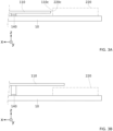
- the sensor element 110 may be positioned in different ways relative to the optical resonator 220, as illustrated in Figures 3A and 3B .
- the sensor element 110 and the optical resonator 220 are located side by side.
- the sensor element 110 then has a flank 110c facing an interaction face 220c of the optical resonator 220.
- the flank 110c of the sensor element 110 located opposite the optical resonator 220 has a shape complementary to the latter. This makes it possible to maximize the mechanical-optical interaction between the mobile mass 110 and the optical detector 200.
- the optical resonator 220 is an optical ring and therefore has a crown shape in projection in the longitudinal plane XY, it is advantageously provided that the sensor element 110 has a concave shape towards the optical resonator 220, that is to say at the level of its flank 110c.
- the sensor element 110 and the optical resonator 220 are located opposite each other in the transverse direction Z.
- the image of one is projected onto the image on the other.
- This embodiment makes it possible to maximize the amplitude of the distance between the sensor element 110 and the optical resonator 220 during the vibration of the sensor element 110.
- This makes it possible to maximize the effect of the vibration on the evanescent field and consequently the opto-mechanical effect.
- the output signal is therefore greater, and the detection sensitivity is therefore improved.
- the optical resonator is advantageously a photonic crystal.
- a resonator of this type has a very concentrated evanescent field out of plane (i.e. here in the transverse direction Z).
- the size of the optical resonance of a photonic crystal is comparable to the typical values that can be given to the width of the beam forming the sensor element 100 (typically between 200 nm and 1 ⁇ m).
- the system 1 is therefore more sensitive than in the case of an optical resonator in the form of a disk or a ring.
- System 1 includes an optical detector 200 as described above.
- the acoustic wave 5 is directly received by the sensor element 110.
- the latter is therefore directly set into vibration at the resonance frequency.
- the sensor element 110 is advantageously connected to the substrate 10 via anchoring points 140.
- the sensor element 110 is connected to the anchoring points 140 via junctions 150, typically beams.
- Each junction 150 is connected at each of its ends to an anchoring point 140, along a coupling axis specific to said junction 150.
- Each junction 150 has the capacity to deform in torsion around its coupling axis.
- the latter is preferably perforated and thus has through openings in the transverse direction Z.
- the sensor element 110 comprises a plurality of beams 116 extending between the junctions 150 and a central region 117 of the sensor element 110.
- the central region 117 has a rectangular shape, preferably square, in projection in the longitudinal plane XY when the system 1 is at rest.
- the central region 117 In projection in the longitudinal plane XY and when the system 1 is at rest, the central region 117 has dimensions L 117,X and L 117,Y taken respectively in the second direction X and in the excitation direction Y.
- L 117,X and L 117,Y are typically each between 1 ⁇ m and 1000 ⁇ m.
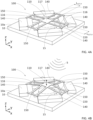
- the system 1 comprises four anchoring points 140 and four junctions 150 each extending between two anchoring points 140. Each coupling axis of the junctions 150 is preferably substantially parallel to one side of the central region 117.
- the sensor element 110 comprises eight beams 116 connecting it to the junctions 150. Two beams 116 connect each side of the central region 117 to the junction 150 located opposite when the system 1 is at rest.
- the beams 116 may each have a length of between 50 nm and 20 ⁇ m, this length being measured in the first direction X or the second direction Y depending on the orientation of the beam 116.
- the senor 100 may have a width of between 3 ⁇ m and 5000 ⁇ m.
- the mechanical sensor 100 advantageously has a plane of symmetry perpendicular to the longitudinal plane XY and comprising the second direction Y. As is also illustrated in the Figures 4A and 4B , the mechanical sensor 100 advantageously has a plane of symmetry perpendicular to the longitudinal plane XY and comprising the first direction X. These symmetries are advantageous for bringing the mechanical sensor 100 into resonance. They are also advantageous for attenuating unwanted vibration modes.
- FIG. 4A and 4B illustrates a particular example of embodiment of the sensor element 110, but it is understood that its structure may be different, in particular the sensor element 110 could comprise another number of beams 116.
- the optical resonator is advantageously a photonic crystal.
- a photonic crystal can in fact have small dimensions, which contributes to the reduction of viscous losses.
- This opening 15 is preferably located, in the transverse direction Z, at least partly under the zone of the mechanical sensor 100 receiving the acoustic wave.
- the opening is preferably located at least partly under the receiving element 120.
- the opening 15 is underlying the entirety of the receiving element 120.
- the opening 15 also extends under at least a portion and preferably the entirety of the sensor element 110.
- the opening is preferably located at least in part under the sensor element 110.
- the opening 15 underlies the entirety of the sensor element 110.
- this opening 15 advantageously accommodates the optical resonator 220 of the optical detector 200. This makes the system both more compact and more robust.
- the mechanical sensor 100 can be formed from a non-resonant membrane, for example made of graphene, coupled to an acoustic resonator.
- the system according to the invention may comprise a plurality of mechanical sensors 100, each mechanical sensor 100 being placed so as to modify an evanescent field of the optical detector 200.
- the system 1 then advantageously comprises as many optical resonators 220, all coupled with the waveguide 210, as mechanical sensors 100.
- Each mechanical sensor 100 can then be associated with an optical resonator 220 for the detection of a different vibration frequency (see Figure 2 ), or all the mechanical sensors 100 can be associated with the same optical resonator 220.
- the mechanical sensors 100 have different dimensions from each other so that each one is capable of being set into vibration at a distinct vibration frequency.
- a system with several mechanical sensors can simultaneously detect several types of gas.
- Photoacoustic spectrometer comprising a system according to the invention
- Another object of the invention relates to a photoacoustic spectrometer comprising a detection system as described previously.
- System 1 can in fact be placed within a cavity 2 which can accommodate one or more gases to be analyzed (see Figure 1 ).
- the cavity 2 then also comprises a first light source 21 enabling so-called detection radiation to be injected into an input 211 of the optical detector 200, as well as means 22 for detecting the radiation at the output 212 of the optical detector 200.
- the cavity 2 also comprises a second light source 30 intended to inject into the cavity 2 so-called excitation radiation making it possible to excite the gas(es) contained in the cavity 2.
- the second light source 30 is typically a modular laser source. The modular nature of the source in fact makes it possible to scan the gas to be analyzed in a range included in its absorption range, typically in an absorption peak.
- the excitation radiation typically the excitation laser, advantageously has a narrower spectral width than the absorption range of the gas to be analyzed. Furthermore, the higher the laser intensity, the more relaxations of molecules composing this gas will be detected and therefore the greater the output signal will be.
- the excitation radiation or laser generally has a main wavelength in the infrared, typically between 1 ⁇ m and 20 ⁇ m. In this range, most molecules have a single absorption line, which is advantageous for analyzing the output signal.
- FIG. 1 illustrates an embodiment of the spectrometer in which the first light source 21 and the second light source 30 are distinct.
- these two sources 21, 30 are in reality one and the same source.
- the radiation would be parallel to the second direction Y.
- the radiation must be focused vertically, in the Z direction, of the receiving element 120, and preferably vertically of the center of the main region 122.
- the acoustic waves are conducted to the mechanical sensor 100 (to the receiving element 120 or to the sensor element 110, depending on the embodiment) by a conduit.
- a conduit In the case of a system comprising several mechanical sensors 100, the presence of several conduits or a conduit having an opening opposite each mechanical sensor 100 is provided. The different conduits - or the single conduit - will then guide and amplify acoustic waves generated by lasers having distinct main wavelengths.
- conduit to conduct the acoustic waves to the receiving element 120 or directly to the sensor element 110 is particularly advantageous when the latter has small dimensions.
- the conduit then makes it possible to focus the wave towards the receiving element and maximize the mechanical-acoustic interaction.
- the choice of whether or not to use a conduit is therefore made mainly according to the dimensions of the receiving element 120 or the sensor element 110.
Landscapes
- Physics & Mathematics (AREA)
- General Health & Medical Sciences (AREA)
- Life Sciences & Earth Sciences (AREA)
- Chemical & Material Sciences (AREA)
- Analytical Chemistry (AREA)
- Biochemistry (AREA)
- Health & Medical Sciences (AREA)
- General Physics & Mathematics (AREA)
- Immunology (AREA)
- Pathology (AREA)
- Acoustics & Sound (AREA)
- Optics & Photonics (AREA)
- Investigating Or Analysing Materials By Optical Means (AREA)
- Investigating Or Analyzing Materials By The Use Of Ultrasonic Waves (AREA)
Applications Claiming Priority (1)
| Application Number | Priority Date | Filing Date | Title |
|---|---|---|---|
| FR2311816A FR3154806A1 (fr) | 2023-10-30 | 2023-10-30 | Système opto-mécanique de transduction pour la spectrométrie photo-acoustique |
Publications (1)
| Publication Number | Publication Date |
|---|---|
| EP4549928A1 true EP4549928A1 (de) | 2025-05-07 |
Family
ID=89661126
Family Applications (1)
| Application Number | Title | Priority Date | Filing Date |
|---|---|---|---|
| EP24209344.1A Pending EP4549928A1 (de) | 2023-10-30 | 2024-10-29 | Optomechanisches wandlersystem für die photoakustische spektrometrie |
Country Status (3)
| Country | Link |
|---|---|
| US (1) | US20250137919A1 (de) |
| EP (1) | EP4549928A1 (de) |
| FR (1) | FR3154806A1 (de) |
Citations (1)
| Publication number | Priority date | Publication date | Assignee | Title |
|---|---|---|---|---|
| EP3509214A1 (de) * | 2018-01-03 | 2019-07-10 | Commissariat à l'énergie atomique et aux énergies alternatives | Mikro- oder nanomechanische vorrichtung zur detektion von partikeln |
-
2023
- 2023-10-30 FR FR2311816A patent/FR3154806A1/fr active Pending
-
2024
- 2024-10-29 US US18/929,773 patent/US20250137919A1/en active Pending
- 2024-10-29 EP EP24209344.1A patent/EP4549928A1/de active Pending
Patent Citations (1)
| Publication number | Priority date | Publication date | Assignee | Title |
|---|---|---|---|---|
| EP3509214A1 (de) * | 2018-01-03 | 2019-07-10 | Commissariat à l'énergie atomique et aux énergies alternatives | Mikro- oder nanomechanische vorrichtung zur detektion von partikeln |
Non-Patent Citations (4)
| Title |
|---|
| LI BEI-BEI ET AL: "Cavity optomechanical sensing", NANOPHOTONICS, vol. 10, no. 11, 24 August 2021 (2021-08-24), pages 2799 - 2832, XP093135588, ISSN: 2192-8614, DOI: 10.1515/nanoph-2021-0256 * |
| MARCEL W. PRUESSNER: "Optomechanical Cavities for All-Optical Photothermal Sensing", ACS PHOTONICS, vol. 5, no. 8, 26 June 2018 (2018-06-26), pages 3214 - 3221, XP093160950, ISSN: 2330-4022, DOI: 10.1021/acsphotonics.8b00452 * |
| SAHAR BASIRI-ESFAHANI ET AL: "Precision ultrasound sensing on a chip", ARXIV.ORG, CORNELL UNIVERSITY LIBRARY, 201 OLIN LIBRARY CORNELL UNIVERSITY ITHACA, NY 14853, 3 May 2018 (2018-05-03), XP081243178 * |
| XINMIAO LIU: "Progress of optomechanical micro/nano sensors: a review", INTERNATIONAL JOURNAL OF OPTOMECHATRONICS, vol. 15, no. 1, 1 January 2021 (2021-01-01), US, pages 120 - 159, XP093160954, ISSN: 1559-9612, DOI: 10.1080/15599612.2021.1986612 * |
Also Published As
| Publication number | Publication date |
|---|---|
| FR3154806A1 (fr) | 2025-05-02 |
| US20250137919A1 (en) | 2025-05-01 |
Similar Documents
| Publication | Publication Date | Title |
|---|---|---|
| EP3754326B1 (de) | Integrierter optischer schaltkreis mit eingekapseltem referenzarm | |
| EP3147673B1 (de) | Optomechanischer physikalischer sensor mit verbesserter empfindlichkeit | |
| EP2930506B1 (de) | Erkennungsvorrichtung mit akustischem resonator für differentialanwendungen vom typ helmholtz-resonator | |
| EP2866000B1 (de) | Optomechanische Vorrichtung zum Betätigen und/oder Erkennen einer Bewegung eines mechanischen Elements, insbesondere für die gravimetrische Erfassung | |
| EP2315019B1 (de) | Photoakustischer gasdetektor | |
| EP3425344B1 (de) | Bewegungssensor mit mikroresonator mit segmentiertem ring | |
| EP3509214B1 (de) | Mikro- oder nanomechanische vorrichtung zur detektion von partikeln | |
| EP3650836B1 (de) | Messvorrichtung basiert auf optischer erfassung der bewegung einer opto-mechanischen kavität | |
| EP3276337A1 (de) | Optische vorrichtung mit mikroresonator mit segmentiertem ring | |
| EP3494381B1 (de) | Absorptionskavität mit eingangs- und ausgangswellenleitern für einen biologischen oder chemischen sensor | |
| EP2569593B1 (de) | Vorrichtung zur optischen messung eines physikalischen parameters | |
| EP2342535A1 (de) | Laserkreisel mit einem festkörper-verstärkungsmedium und einem optischen ringresonator | |
| FR3124592A1 (fr) | Système de mesure de type MEMS ou NEMS multicapteurs | |
| EP2526407B1 (de) | Verfahren zur Erkennung eines resonanten nichtlinearen optischen Signals und Vorrichtung zur Umsetzung dieses Verfahrens | |
| EP4549928A1 (de) | Optomechanisches wandlersystem für die photoakustische spektrometrie | |
| EP0942261A1 (de) | Verfahren und Vorrichtung für Messen von Trichertiefen in einer physico-chemischen Analysevorrichtung | |
| WO2009127794A1 (fr) | Spectrometre compact a echantillonage bidimensionnel | |
| FR2590015A1 (fr) | Dispositif interferometrique en anneau reciproque a fibre optique monomode | |
| FR3056750A1 (fr) | Detecteur d'une substance fluide | |
| EP4155717B1 (de) | Vorrichtung und verfahren zum nachweis chemischer oder biologischer spezies | |
| FR2680012A1 (fr) | Dispositif de dispersion spectrale. | |
| FR3154721A1 (fr) | Système opto-mécanique de transduction à détection améliorée | |
| FR3162278A1 (fr) | Dispositif de spectroscopie photoacoustique | |
| EP4671695A1 (de) | Verbessertes mems- oder nms-messsystem mit mehreren sensoren | |
| WO2025036781A1 (fr) | Systeme de controle de depot de couches minces comportant une cavite optique |
Legal Events
| Date | Code | Title | Description |
|---|---|---|---|
| PUAI | Public reference made under article 153(3) epc to a published international application that has entered the european phase |
Free format text: ORIGINAL CODE: 0009012 |
|
| STAA | Information on the status of an ep patent application or granted ep patent |
Free format text: STATUS: REQUEST FOR EXAMINATION WAS MADE |
|
| 17P | Request for examination filed |
Effective date: 20241029 |
|
| AK | Designated contracting states |
Kind code of ref document: A1 Designated state(s): AL AT BE BG CH CY CZ DE DK EE ES FI FR GB GR HR HU IE IS IT LI LT LU LV MC ME MK MT NL NO PL PT RO RS SE SI SK SM TR |