EP3509849B1 - Mécanisme de verrouillage mécanique pour éjection de fluide - Google Patents
Mécanisme de verrouillage mécanique pour éjection de fluide Download PDFInfo
- Publication number
- EP3509849B1 EP3509849B1 EP17895514.2A EP17895514A EP3509849B1 EP 3509849 B1 EP3509849 B1 EP 3509849B1 EP 17895514 A EP17895514 A EP 17895514A EP 3509849 B1 EP3509849 B1 EP 3509849B1
- Authority
- EP
- European Patent Office
- Prior art keywords
- coding
- fluid ejection
- coding elements
- ejection device
- printer
- Prior art date
- Legal status (The legal status is an assumption and is not a legal conclusion. Google has not performed a legal analysis and makes no representation as to the accuracy of the status listed.)
- Active
Links
Images







Classifications
-
- B—PERFORMING OPERATIONS; TRANSPORTING
- B41—PRINTING; LINING MACHINES; TYPEWRITERS; STAMPS
- B41J—TYPEWRITERS; SELECTIVE PRINTING MECHANISMS, i.e. MECHANISMS PRINTING OTHERWISE THAN FROM A FORME; CORRECTION OF TYPOGRAPHICAL ERRORS
- B41J29/00—Details of, or accessories for, typewriters or selective printing mechanisms not otherwise provided for
- B41J29/17—Cleaning arrangements
-
- B—PERFORMING OPERATIONS; TRANSPORTING
- B41—PRINTING; LINING MACHINES; TYPEWRITERS; STAMPS
- B41J—TYPEWRITERS; SELECTIVE PRINTING MECHANISMS, i.e. MECHANISMS PRINTING OTHERWISE THAN FROM A FORME; CORRECTION OF TYPOGRAPHICAL ERRORS
- B41J2/00—Typewriters or selective printing mechanisms characterised by the printing or marking process for which they are designed
- B41J2/005—Typewriters or selective printing mechanisms characterised by the printing or marking process for which they are designed characterised by bringing liquid or particles selectively into contact with a printing material
- B41J2/01—Ink jet
- B41J2/135—Nozzles
- B41J2/14—Structure thereof only for on-demand ink jet heads
- B41J2/1433—Structure of nozzle plates
-
- B—PERFORMING OPERATIONS; TRANSPORTING
- B41—PRINTING; LINING MACHINES; TYPEWRITERS; STAMPS
- B41J—TYPEWRITERS; SELECTIVE PRINTING MECHANISMS, i.e. MECHANISMS PRINTING OTHERWISE THAN FROM A FORME; CORRECTION OF TYPOGRAPHICAL ERRORS
- B41J2/00—Typewriters or selective printing mechanisms characterised by the printing or marking process for which they are designed
- B41J2/005—Typewriters or selective printing mechanisms characterised by the printing or marking process for which they are designed characterised by bringing liquid or particles selectively into contact with a printing material
- B41J2/01—Ink jet
- B41J2/17—Ink jet characterised by ink handling
- B41J2/175—Ink supply systems ; Circuit parts therefor
- B41J2/17503—Ink cartridges
- B41J2/1752—Mounting within the printer
-
- B—PERFORMING OPERATIONS; TRANSPORTING
- B41—PRINTING; LINING MACHINES; TYPEWRITERS; STAMPS
- B41J—TYPEWRITERS; SELECTIVE PRINTING MECHANISMS, i.e. MECHANISMS PRINTING OTHERWISE THAN FROM A FORME; CORRECTION OF TYPOGRAPHICAL ERRORS
- B41J2/00—Typewriters or selective printing mechanisms characterised by the printing or marking process for which they are designed
- B41J2/005—Typewriters or selective printing mechanisms characterised by the printing or marking process for which they are designed characterised by bringing liquid or particles selectively into contact with a printing material
- B41J2/01—Ink jet
- B41J2/17—Ink jet characterised by ink handling
- B41J2/175—Ink supply systems ; Circuit parts therefor
- B41J2/17503—Ink cartridges
- B41J2/17543—Cartridge presence detection or type identification
- B41J2/17546—Cartridge presence detection or type identification electronically
-
- B—PERFORMING OPERATIONS; TRANSPORTING
- B41—PRINTING; LINING MACHINES; TYPEWRITERS; STAMPS
- B41J—TYPEWRITERS; SELECTIVE PRINTING MECHANISMS, i.e. MECHANISMS PRINTING OTHERWISE THAN FROM A FORME; CORRECTION OF TYPOGRAPHICAL ERRORS
- B41J2/00—Typewriters or selective printing mechanisms characterised by the printing or marking process for which they are designed
- B41J2/005—Typewriters or selective printing mechanisms characterised by the printing or marking process for which they are designed characterised by bringing liquid or particles selectively into contact with a printing material
- B41J2/01—Ink jet
- B41J2/17—Ink jet characterised by ink handling
- B41J2/175—Ink supply systems ; Circuit parts therefor
- B41J2/17503—Ink cartridges
- B41J2/17553—Outer structure
-
- B—PERFORMING OPERATIONS; TRANSPORTING
- B41—PRINTING; LINING MACHINES; TYPEWRITERS; STAMPS
- B41J—TYPEWRITERS; SELECTIVE PRINTING MECHANISMS, i.e. MECHANISMS PRINTING OTHERWISE THAN FROM A FORME; CORRECTION OF TYPOGRAPHICAL ERRORS
- B41J29/00—Details of, or accessories for, typewriters or selective printing mechanisms not otherwise provided for
- B41J29/38—Drives, motors, controls or automatic cut-off devices for the entire printing mechanism
-
- B—PERFORMING OPERATIONS; TRANSPORTING
- B41—PRINTING; LINING MACHINES; TYPEWRITERS; STAMPS
- B41J—TYPEWRITERS; SELECTIVE PRINTING MECHANISMS, i.e. MECHANISMS PRINTING OTHERWISE THAN FROM A FORME; CORRECTION OF TYPOGRAPHICAL ERRORS
- B41J29/00—Details of, or accessories for, typewriters or selective printing mechanisms not otherwise provided for
- B41J29/38—Drives, motors, controls or automatic cut-off devices for the entire printing mechanism
- B41J29/393—Devices for controlling or analysing the entire machine ; Controlling or analysing mechanical parameters involving printing of test patterns
Definitions
- Some fluid ejection systems may employ fluid ejection devices for ejecting non-transparent fluids, e.g. black or colored ink, onto a medium, such as paper.
- non-transparent fluids e.g. black or colored ink
- EP 0 816 098 A2 discloses a printer comprising a fluid ejection device and an ink container having latch features.
- the fluid ejection device may comprise a print head comprising an array of nozzles.
- the fluid ejection device may be assigned to a specific ink color, e.g. cyan, magenta, yellow and black ("key").
- Fluid ejection devices may be mounted on a carriage that moves over the printable medium while the fluid ejection devices eject ink through the nozzles.
- fluid ejection devices may comprise support members coupled to a plurality of fluid ejection dies arranged along a width of the support members.
- the carriage may comprise a number of carriage slots corresponding to the fluid ejection device. Inserting a fluid ejection device that has been assigned to a certain ink color into an incorrect carriage slot, i.e. a carriage slot that is assigned to a different ink color, may lead to incorrect print results and may even cause damage to the printer due to clogging of the ink. It is therefore desirable to prevent print heads from being inserted into an incorrect carriage slot or at least warn the user of such an incorrect insertion.
- a fluid ejection device may comprise a fluid ejection die that may buffering and eject fluid supplied from a fluid reservoir.
- a fluid ejection device may include any types of devices implemented to controllably eject fluid drops.
- a fluid ejection device may be employed with printers, three-dimensional printers, fluid analysis and titration sys-tems.
- a fluid ejection device may comprise a printhead module that includes at least one printhead to eject drops of ink supplied from an ink reservoir of a printer.
- the fluid ejection device may comprise three dimensional print agent distributors or lab-on-a-chip devices to controllably eject fluid drops.
- a print head may be referred to as generic, or universal, print head.
- the fluid ejection device with a generic print head may be usable for any ink color and therefore may not comprise a fixed mechanical key mechanism.
- a fluid ejection device with a generic print head that has been in use in a printer may be dismounted, e.g. for cleaning or repair purpose. In this case, the fluid ejection, device should be remounted on the correct carriage slot in order to prevent incorrect print results and damage to the printer.
- a fluid ejection device in an example, may comprise a set of coding elements, each coding element movable between an initial position and a coded position, and a trap element, to trap one or a plurality of the coding elements in the initial position when at least another one or a plurality of other ones of the coding elements is moved from the initial position to the coded position.
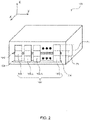
- Fig. 1 shows a schematic view of a fluid ejection device 100 according to an example.
- the fluid ejection device 100 comprises a set of coding elements 102.
- the set 102 comprises n coding elements 102-1 to 102-n.
- Each of the coding elements 102-1 to 102-n is movable between an initial position Pi and a doded position Pc.
- Fig. 1 shows the coding elements 102-1 to 102-n disposed in the initial position Pi, as indicated by the solid line of the coding elements 102-1 to 102-n.
- the coded position Pc is indicated by dashed lines in Fig. 1 .
- the number n of the coding elements 102-1 to 102-n corresponds to the number of ink colors used by a specific printer. For example, if a printer uses cyan, magenta, yellow and black ink colors, the fluid ejection device comprises four coding elements 102-1 to 102-4.
- the term initial position is not limited to the exact position of the coding elements 102-1 to 102-n before the coding operation.
- the initial position rather refers to a complementary position to the coded position, i.e. any position to which the coding elements 102-1 to 102-n are movable besides the coded position.
- the initial position can relate to a range of positions between two boundary positions.
- coding operation An operation, by which one or a plurality of the coding elements 102-1 to 102-n is moved from the initial position Pi to the coded position Pc, is referred to as coding operation.
- the coding operation causes the set of coding elements 102 to be insertable only in a carriage slot, with the corresponding lockout mechanism, as will be described in detail later.
- the fluid ejection device 100 further comprises a trap element 104 to trap one or a plurality of other ones of the coding elements 102-1 to 102-n. Trapping by the trap element 104 may refer to mechanically blocking one or a plurality of the coding elements 102-1 to 102-n from moving to the coded position Pc.
- the trap element 104 is movable between a pre-coding position 104i and a post-coding position 104f, relating to a position of the trap element before and after the coding operation, respectively.
- the post-coding position also is referred to as coding position.
- the coding elements 102-1 to 102-n are disposed in the initial position Pi, and the trap element 104 is disposed in the pre-coding position 104i.
- the trap element 104 is disposed so as to move to the coding position 104f when at the least one of the coding elements 102-1 to 102-n is moved from the initial position Pi to the coded position Pc.
- FIG. 2 schematically shows the fluid ejection device 100 after a coding operation has been performed.
- a coding element 102-1 has been moved from the initial position Pi to the coded position Pc during the coding operation.
- the rest of the coding elements 102-2 to 102-n remains in the initial position Pi.
- the trap element 104 has been moved from the pre-coding position 104i to the coding position 104f. In the coding position 104f, the trap element 104 blocks the remaining coding elements 102-2 to 102-n from moving to the coded position Pc.
- the trap element 104 may be provided as a beam-shaped element extending along a first axis, also referred to as y-axis, and may have a polygonal cross section.
- the first axis may be perpendicular to the movement direction of the coding elements 102-1 to 102-n between the initial position Pi and the coded position Pc.
- the trap element 104 extends along the y-axis, and the coding elements 102-1 to 102-n are movable along the z-axis.
- the trap element 104 In the coding position 104f, the trap element 104 mechanically blocks any of the coding elements 102-1 to 102-n from moving to the coded position Pc.
- the fluid ejection device 100 allows for a mechanical coding of a set of coding elements 102, wherein the set of coding elements 102 is mechanically prevented from being further modified. By this means, the fluid ejection device 100 can only be inserted into a slot having a lockout unit corresponding to the mechanical coding of the set of coding elements 102. Hence, there is provided a mechanical lockout mechanism for a fluid ejection device.
- Fig. 3 shows a schematic view of another example of the fluid ejection device 100 having a lock element 106.
- the lock element 106 is immovably disposed in a position overlapping the coded position Pc of the coding elements 102-1 to 102-n. Any of the coding elements 102-1 to 102-n that is moved to the coded position Pc can engage with the lock element 106 and thereby can be held in the coded position Pe.
- the coding element 102-1 to 102-n comprises a hook portion, a recess portion or a protruding portion to engage with the lock element 106.
- Fig. 4 shows a lockout unit 400 according to an example to mechanically engage with a set of coding elements, in particular the set of coding elements 102 of Fig. 1 to 3 .
- the lockout unit 400 comprises a base member 402, on which one or a plurality of push members 404 is disposed.
- the lockout unit 400 comprises one push member 404.
- the push member 404 is positioned in the leftmost position, whereas dashed lines indicate other possible positions 406 for the push member 404.
- the number of possible positions 406, including the position of the actual push member 404, may correspond to the number of the coding elements of the fluid ejection device that is to be engaged with.
- the push member 404 may be dimensioned so as to correspond to one of the coding elements, for example the coding elements 102-1 to 102-n of Fig. 1 to 3 .
- a fluid ejection device, for example the fluid ejection device 100 of Fig. 1 to 3 may be engageable with the lockout unit 400 by being inserted from above (in the orientation of the respective figure).
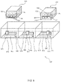
- Fig. 5 shows a carriage 500 having three carriage slots 502, 504, 506 according to an example.
- a first carriage slot 502 has a first lockout unit 508, a second carriage slot 504 has a second lockout unit 510, and a third carriage slot 506 has a third lockout unit 512.
- Each of the lockout units 508, 510, 512 has a base member 514 that is attached to the respective lockout unit 508, 510, 512.
- a push member 516 and a trigger member 518 protrude from a top surface of the base member 514.
- the push member 516 of the first carriage slot 502 is positioned on a left site
- the push member 516 of the second carriage slot 504 is positioned on a center site
- the push member of the third carriage slot 506 is positioned on a right site of the respective lockout unit 508, 510, 512.
- the push member 516 extends and is shaped so as to push a coding element into its coded position
- the push member 404, 516 has a cuboid shape.
- the push member 516 may have any other geometric shape, e.g. of a round column, of a cone, of an angled column or a combination thereof.
- the trigger member 518 extends and is shaped so as to push the trap element of a fluid ejection device from its pre-coding position to a coding position.
- the trigger member 518 may have the shape of an elongated beam as shown in Fig. 5 .
- the trigger member 518 comprise a plurality of blocks protruding towards a fluid ejection device.
- the height of the trigger member 518 may be less than the height of the push member 516, wherein the height relates to an expansion in the direction towards the fluid ejection device, i.e. along the z-axis.
- Fig. 5 further shows a first fluid ejection device 520 above the first carriage slot 502.
- the first fluid ejection device 520 comprises three coding elements 524 and a trap element. 526,
- the first fluid ejection device 520 has not been coded yet, i.e. none of its coding elements 524 has been moved from their initial positions Pi to a coded position Pe.
- the coding operation can be performed by mounting the first fluid ejection device 520 on the first carriage slot 502, thereby engaging the coding elements 524 with the first lockout unit 508.
- the push member 516 pushes the left one of the coding elements 524 from the initial position Pi to the coded position Pe.
- the trigger member 518 pushes the trap element 526 from its pre-coding position to a coding position.
- Fig. 5 shows a second fluid ejection device 522 above the third carriage slot 506.
- the second fluid ejection device 522 comprises three coding elements, consisting of a left coding element 528, a middle coding element 530 and a right coding element 532, and a trap element 534.
- the second fluid ejection device 522 has undergone a coding operation by being mounted on the third carriage slot 506.
- the coding element 532 has been moved to the coded position Pe
- the trap element 536 has been moved to the coding position by the coding operation
- the left and middle coding elements 528, 530 remain in the initial position Pi.
- the trap element 532 blocks the left and middle coding elements 528, 530 from moving to the coded position Pe.
- the left and middle coding elements 528, 530 respectively, will strike against the push member 516 and thereby block the second fluid ejection device from fully mounted.
- Fig. 6 shows a further example of a fluid ejection device 600 with a generic print head.
- the fluid ejection device 600 has the shape of a cassette with a cascaded front wall 602, on which three coding elements 604, 606, 608 are disposed.
- the coding elements 604, 606, 608 have an elongated shape and are arranged parallel to one another.
- the fluid ejection device 600 further comprises a trap element 610 and a lock element 612.
- the trap element 610 has the shape of a beam extending perpendicular to the coding elements 604, 606, 608.
- the coding elements 604, 606, 608 can engage with the lock element 612, if and when they are moved to their coded position.
- Fig. 7 shows a partial view of the fluid ejection device 600 of Fig. 6 .
- Each of the coding elements 604 606, 608 comprises a hook portion 614 and a support portion 616 that correspond to end portions of the coding elements 604, 606, 608.
- Each hook portion 614 and the corresponding support portion 616 are connected by a connection portion 618.
- Each of the hook portions 614 and the support portion 616 has the shape of a cylinder on one side and the shape of a ramp on the opposite side. The ramps of the hook portions 614 and the support portion 616 grow along the elongation axis of each of the coding elements 604, 606, 608 to-wards the respective center.
- connection portions 618 comprise an elastic material such that the coding elements 604, 606, 608 are bendable between the respective hook portion 614 and the support portion 616.
- a frame 620 that is attached to the front wall 602 holds the coding elements 604, 606, 608.
- the frame 620 has side walls 624, spacers 626 and a pin 628 to house parts of the coding elements 604, 606, 608 in between.
- the trap element 610 is movably disposed within a groove 622 that is formed into the front wall 602.
- the trap element is 610 is movable between a pre-coding position that is the lowermost position within the group 622 and a coding position that is any position above the support portion 616 of one or a plurality of of the coding elements 604, 606, 608.
- the trap element 610 has a sloped surface that is tilted with respect to the front wall 602. In their initial position as shown in Fig. 6 and 7 , the support portions 616 of the coding elements 604, 606, 608 abut against the sloped surface of the trap element 610.
- the lock element 612 comprises a lock ramp 630 on which the hook portion 614 of the coding iatas 604, 606, 608 can glide.
- the lock element 612 further comprises a strike surface 632 on which the coding elements 604, 606, 608 can rest when brought into a coded position.
- Fig. 8 shows a first lockout unit 800 and a second lockout unit 802 according to an example.
- Each of the first and second lockout units 800, 802 comprises a base member 801 on which three compartments 804, 806, 808 are formed that correspond to the three coding elements 604, 606, 608 of the fluid ejection device 600 of Fig. 6 and 7 .
- a push member 810 in disposed in one of the compartments 804, 806, 808.
- the push member 810 has the shape of a column with a semicircular cross section.
- the push member 810 of the first lockout unit 800 is positioned in the left compartment 804 (in the orientation of Fig. 8 ), whereas push member 810 of the second lockout unit 802 is positioned in the right compartment 808.
- the first and second lockout units 800, 802 further comprise a. trigger member 812 protruding upwards from the respective base member 801.
- the trigger member 812 has the shape of a finger-shaped wall, i.e. a wall with two alternate heights.
- the trigger member 812 is further supported by a plurality of struts 814 that are formed on top of the base member 801.
- the struts 814 further divide the top surface of the base member 801 into the compartments 804, 806, 808.
- Fig. 9 shows a partial view of the fluid ejection device 600 of Fig. 6 and 7 being engaged with the first lockout unit 800 of Fig. 8 , thereby undergoing a coding operation.
- the push member 810 has pushed the left coding element 604 into its coded position.
- the hook portion 614 of the coding element 604 has moved along the lock ramp 630 of the lock element 612 and rests on the strike surface 632 thereof.
- the trap element 610 has been pushed upwards by the trigger member 812 and has been moved to the coding position above the support portions 616 of the coding elements 606, 608.
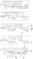
- FIG. 10 and 11 show subsequent cross-sectional views 10A - 10E and 11A - 11E of the coding element 604 and the coding element 608, respectively, during the coding operation of fig. 9 .
- Views 10A and 11A show the coding elements 604, 608 before the coding operation, i.e. before being engaged with a lockout unit, when the trap element 610 is in the pre-coding position.
- the respective coding element 604, 608 is clamped between the trap element 610 and the lock element 612.
- the push member 810 pushes the coding element 604 upwards.
- the hook portion 614 of the coding elements 604 glides along the lock ramp 630 of the lock element 612. While gliding, the hook portion 614 experiences resistance due to friction at the surface of the lock ramp 630 and due to deformation of the connection portion 618.
- the resistance is indicated by a hatched area A in which the hook portion 614 and the lock element 612 intersect.
- the trigger member 812 abuts against the trap element 610 from below.
- the hook portion 614 has almost overcome the lock element 612. Meanwhile, the trigger member 812 lifts the trap element 610.
- the fluid ejection device 600 has been released.
- the coding element 604 is no more supported by the push member 810.
- the hook portion 614 rests on the strike surface 632 of the lock element 612.
- lock element 612 engages with the coding elements 604, thereby holding it in its coded position.
- the view 11A shows a pre-coding state as mentioned above.
- the trap element 610 is lifted by the trigger member 812.
- the sloped surface of the support portion 616 rests on the sloped surface of the trap element 610. This causes the coding element 604 to be lifted by the trigger member 812 as well.
- the hook portion 614 of the coding element 608 abuts against the lock element 612.
- the pushing force is transferred via the sloped surfaces of the trap element 610 and the support portion 616.
- the hook portion 614 glides along the lock ramp 632, because the inclination of the sloped surface of the trap element 610 with respect to the front wall 602 is greater than the inclination of the lock ramp 632.
- the friction resistance between the lock element 612 and the hook portion 614 increases due to an increase of the contact area, and the deformation resistance against bending the coding element 608 increases as well. Once these resistance forces overweigh the upwards pushing force, , the coding element 608 stops advancing upwards.
- the connection portion 618 bends and causes the support portion 616 snap below the trap element
- the trap element 610 thereby has been pushed past the support portion 616 of the coding element 608 by the trigger element 812.
- the trap element 610 is in the coding position that is above the support portion 616 in this example. Accordingly, the pre-coding position and the coding position of the trap element 610 are on opposite sides of the support portion 616. The trap element 610 has been moved between the support portion 616 and the hook portion 614.
- View 11E illustrates a situation in which the coding element 608 is being pushed by the push member 814.
- the support portion 616 receives the lifting force from the push member 814.
- the support portion 616 strikes against the trap element 610, causing it to abut against the upper wall of the groove 622.
- the trap element 610 cannot advance further, thereby blocking the coding elements 608 from moving upwards.
- the coding element. 608 is trapped by the trap element 610 in the initial position.
- Fig. 12 illustrates the coding elements 604, 606, 608 that have been coded according to Fig. 7 engaging with the first lockout unit 800 and the second lockout unit 802.
- a fluid ejection device having the coding elements 604, 606, 608 can be mounted on and dismounted from a carriage slot having the first lockout unit 800 without being mechanically blocked, as shown on the left hand side of Fig. 12 .
- the push member 810 of the second lockout unit 802 strikes against the third coding element 608 which cannot be moved upwards because of the trap element 610 being in the coding position, as shown on the right hand side of Fig. 12 .
- inserting the fluid ejection device having the coding elements 604, 606, 608 into a carriage slot having the second lockout unit 802 is mechanically Mocked.
- a printer may comprise a fluid ejection device and a first slot and a second slot.
- the fluid ejection device may have a set of coding elements. Each coding element may be movable between an initial position and a coded position.
- the first slot and the second slot may each receive the fluid ejection device.
- the first slot and the second slot may have a first lockout unit and a second lockout unit, respectively.
- Each lockout unit may mechanically engage with the set of coding elements.
- the first lockout unit may have a pushing member to push one of the coding elements into the coded position.
- the second lockout unit may have another pushing member to push another one of the coding elements into the coded position.
- the fluid ejection device may comprise a trap element to trap one or a plurality of other coding elements in the initial position when the one of the coding elements is moved from the initial position to the coded position.
- a method may be applicable to any of the above described examples of fluid ejection devices, lockout units or a printer.
Landscapes
- Ink Jet (AREA)
Claims (14)
- Imprimante comprenant :un dispositif d'éjection de fluide (100 ; 520, 522 ; 600) ayant un ensemble d'éléments de codage (102 ; 524, 528, 530, 532 ; 604, 606, 608), chaque élément de codage (102 ; 524, 528, 530, 532 ; 604, 606, 608) étant mobile entre une position initiale (Pi) et une position codée (Pc), chacun des éléments de codage (100 ; 520, 522 ; 600) comprenant une partie crochet (614) et une partie support (616) qui correspondent aux parties d'extrémité des éléments de codage (102 ; 524, 528, 530, 532 ; 604, 606, 608), chaque partie crochet (614) et la partie support correspondante (616) étant reliées par une partie liaison (618) ; etune première fente (502) et une deuxième fente (504) chacune conçues pour recevoir le dispositif d'éjection de fluide (100 ; 520, 522 ; 600), la première fente (502) ayant une première unité de verrouillage (508, 800) et la deuxième fente (504) ayant une deuxième unité de verrouillage (510, 802), chaque unité de verrouillage (508, 510, 800, 802) étant conçue pour entrer en prise mécaniquement avec l'ensemble d'éléments de codage (102 ; 524, 528, 530, 532 ; 604, 606, 608),la première unité de verrouillage (508, 800) ayant un élément de poussée (516) conçu pour pousser l'un des éléments de codage (102 ; 524, 528, 530, 532 ; 604, 606, 608) dans la position codée (Pc) et la deuxième unité de verrouillage (510, 802) ayant un autre élément de poussée (516) conçu pour pousser un autre des éléments de codage (102 ; 524, 528, 530, 532 ; 604, 606, 608) dans la position codée (Pc) ;le dispositif d'éjection de fluide (100 ; 520, 522 ; 600) comprenant un élément de piège (104 ; 526, 534 ; 610) conçu pour piéger un ou une pluralité d'autres éléments de codage (102 ; 524, 528, 530, 532 ; 604, 606, 608) en position initiale (Pi) lors du déplacement de l'un des éléments de codage (102 ; 524, 528, 530, 532 ; 604, 606, 608) de la position initiale (Pi) à la position codée (Pc).
- Imprimante selon la revendication 1,l'élément de piège (104 ; 526, 534; 610) étant destiné à se déplacer d'une position de précodage (104i) à une position de codage (104f) lors du déplacement de l'un ou d'une pluralité d'autres éléments de codage (102 ; 524, 528, 530, 532 ; 604, 606, 608) de la position initiale (Pi) à la position codée (Pc) ; etdans la position de codage (104f), l'élément de piège (104 ; 526, 534; 610) étant destiné à bloquer le déplacement de l'un quelconque des éléments de codage (102 ; 524, 528, 530, 532 ; 604, 606, 608) vers la position codée (Pc), le piégeant ainsi (102 ; 524, 528, 530, 532 ; 604, 606, 608) dans la position initiale (Pi).
- Imprimante selon la revendication 2,
un sens de déplacement (Z) de l'élément de piège (104; 526, 534; 610) de la position de précodage (104i) à la position de codage (104f) étant parallèle au sens de déplacement de l'un ou d'une pluralité des autres éléments de codage (102 ; 524, 528, 530, 532; 604, 606, 608). - Imprimante selon la revendication 2,chacun des éléments de codage (102 ; 524, 528, 530, 532 ; 604, 606, 608) comprenant une partie de support (616) conçue pour bloquer le déplacement de l'élément de piège (104 ; 526, 534 ; 610) de la position de codage (104f) à la position de précodage (104i) ; etla position de précodage (104i) et la position de codage (104f) de l'élément de piège (104; 526, 534 ; 610) se trouvant sur des côtés opposés par rapport à la partie de support (616).
- Imprimante selon la revendication 1,
l'élément de piège (104 ; 526, 534 ; 610) étant disposé de manière mobile à l'intérieur d'une rainure (622) formée dans une surface (602) du dispositif d'éjection de fluide (100 ; 520, 522 ; 600) ou sur celle-ci. - Imprimante selon la revendication 1, comprenant en outre
un élément de verrouillage (612) destiné à entrer en prise avec l'un ou une pluralité d'autres éléments de codage (102 ; 524, 528, 530, 532 ; 604, 606, 608) lorsqu'il est amené dans la position codée (Pc). - Imprimante selon la revendication 6,l'élément de verrouillage (612) comprenant une rampe de verrouillage (630) le long de laquelle l'un ou une pluralité des autres des éléments de codage (102 ; 524, 528, 530, 532 ; 604, 606, 608) est conçu pour glisser afin de se déplacer de la position initiale (Pi) à la position codée (Pc) ; etla rampe de verrouillage (630) étant disposée pour augmenter une ou une pluralité de résistances au frottement et de résistance à la déformation contre le mouvement d'un élément de codage quelconque (102 ; 524, 528, 530, 532 ; 604, 606, 608) de la position initiale (Pi) à la position codée (Pc).
- Imprimante selon la revendication 7,l'élément de piège (104 ; 526, 534; 610) comprenant une rampe de support opposée à la rampe de verrouillage (630) ; etune pente de la rampe de support étant supérieure à une pente de la rampe de verrouillage (630).
- Imprimante selon la revendication 6,
l'élément de verrouillage (612) étant positionné de telle sorte que les éléments de codage (102 ; 524, 528, 530, 532 ; 604, 606, 608) sont serrés entre l'élément de verrouillage (612) et l'élément de piège (104 ; 526, 534 ; 610), lorsque les éléments de codage (102 ; 524, 528, 530, 532 ; 604, 606, 608) se trouvent dans la position initiale (Pi) et l'élément de piège se trouve dans la position de précodage (Pc). - Imprimante selon la revendication 1,
les éléments de codage (102 ; 524, 528, 530, 532 ; 604, 606, 608) comprenant un matériau élastique, en particulier du caoutchouc ou un polymère. - Imprimante selon la revendication 1,
chacune de la première unité de verrouillage (508) et de la deuxième unité de verrouillage (510) comprenant en outre un élément de déclenchement (518, 812) pour déplacer l'élément de piège (104 ; 526, 534; 610) vers la position de codage (104f), dans laquelle l'élément de piège (104 ; 526, 534 ; 610) est conçu pour bloquer le déplacement de l'un quelconque des éléments de codage (102 ; 524, 528, 530, 532 ; 604, 606, 608) vers la position codée (Pc), piégeant ainsi celui-ci (102 ; 524, 528, 530, 532 ; 604, 606, 608) dans la position initiale (Pi). - Imprimante selon la revendication 1, comprenant en outre
une troisième fente (506) ayant une troisième unité de verrouillage (512) ayant un autre élément de poussée (516) conçu pour pousser un autre élément de codage (102 ; 524, 528, 530, 532 ; 604, 606, 608) dans la position codée (Pc). - Imprimante selon la revendication 1, comprenant en outre
un chariot (500) comportant la première fente (502) et la deuxième fente (504) conçues pour recevoir le dispositif d'éjection de fluide (100 ; 520, 522 ; 600) et un ou une pluralité d'un autre dispositif d'éjection de fluide (100 ; 520, 522 ; 600) qui est similaire ou identique au dispositif d'éjection de fluide (100 ; 520, 522 ; 600). - Procédé de codage mécanique d'un dispositif d'éjection de fluide (100 ; 520, 522 ; 600) sur une fente (502, 504, 506) d'une imprimante, comprenant :la fourniture au dispositif d'éjection de fluide (100 ; 520, 522 ; 600) d'un ensemble d'éléments de codage (102 ; 524, 528, 530, 532 ; 604, 606, 608), chaque élément de codage (102 ; 524, 528, 530, 532 ; 604, 606, 608) mobile entre une position initiale (Pi) et une position codée (Pc) ;la fourniture au dispositif d'éjection de fluide (100 ; 520, 522 ; 600) comprenant un élément de piège (104 ; 526, 534; 610) pour piéger l'un quelconque des éléments de codage (102 ; 524, 528, 530, 532 ; 604, 606, 608) en position initiale (Pi) ;la fourniture de la fente (502, 504, 506) avec un élément de poussée (516) pour pousser l'un des éléments de codage (102 ; 524, 528, 530, 532 ; 604, 606, 608) dans la position codée (Pc) ;le montage du dispositif d'éjection de fluide (100 ; 520, 522 ; 600) sur la fente (502, 504 506) ;la poussée, par l'élément de poussée (516), d'un premier de l'élément de codage (102 ; 524, 528, 530, 532 ; 604, 606, 608) dans la position codée (Pc) ; etle maintien, par l'élément de piège (104 ; 526, 534; 610), d'un ou d'une pluralité de seconds éléments de codage (102 ; 524, 528, 530, 532 ; 604, 606, 608) dans la position initiale (Pi).
Applications Claiming Priority (1)
| Application Number | Priority Date | Filing Date | Title |
|---|---|---|---|
| PCT/US2017/017485 WO2018147869A1 (fr) | 2017-02-10 | 2017-02-10 | Mécanisme de verrouillage mécanique pour éjection de fluide |
Publications (3)
| Publication Number | Publication Date |
|---|---|
| EP3509849A1 EP3509849A1 (fr) | 2019-07-17 |
| EP3509849A4 EP3509849A4 (fr) | 2020-05-06 |
| EP3509849B1 true EP3509849B1 (fr) | 2022-09-07 |
Family
ID=63107978
Family Applications (1)
| Application Number | Title | Priority Date | Filing Date |
|---|---|---|---|
| EP17895514.2A Active EP3509849B1 (fr) | 2017-02-10 | 2017-02-10 | Mécanisme de verrouillage mécanique pour éjection de fluide |
Country Status (3)
| Country | Link |
|---|---|
| US (1) | US10864731B2 (fr) |
| EP (1) | EP3509849B1 (fr) |
| WO (1) | WO2018147869A1 (fr) |
Family Cites Families (11)
| Publication number | Priority date | Publication date | Assignee | Title |
|---|---|---|---|---|
| US1858389A (en) * | 1930-02-04 | 1932-05-17 | Sloane Blabon Corp | Control device |
| DE69715529T2 (de) * | 1996-06-27 | 2003-06-05 | Hewlett-Packard Co. (N.D.Ges.D.Staates Delaware), Palo Alto | Kodierungsvorrichtung für Tintenzufuhrbehälter |
| US6290346B1 (en) | 2000-01-05 | 2001-09-18 | Hewlett-Packard Company | Multiple bit matrix configuration for key-latched printheads |
| ES2275603T5 (es) | 2000-10-20 | 2010-07-07 | Seiko Epson Corporation | Dispositivo de registro de inyeccion de tinta y cartucho de tinta. |
| FR2831855B1 (fr) * | 2001-11-06 | 2004-04-02 | Gemplus Card Int | Agencement d'alimentation en fluide d'une machine comportant des moyens de detrompage |
| JP2003237083A (ja) | 2002-02-15 | 2003-08-26 | Canon Inc | 液体噴射記録ヘッド、および、それを備えた液体噴射記録装置 |
| US7004564B2 (en) * | 2003-07-31 | 2006-02-28 | Hewlett-Packard Development Company, L.P. | Printing-fluid container |
| WO2010134907A1 (fr) | 2009-05-18 | 2010-11-25 | Hewlett-Packard Development Company, L.P. | Élément d'impression remplaçable |
| JP5861298B2 (ja) * | 2010-09-03 | 2016-02-16 | セイコーエプソン株式会社 | 液体供給装置および液体噴射システム |
| US8651645B2 (en) | 2010-10-29 | 2014-02-18 | Hewlett-Packard Development Company, L.P. | Print cartridge identification system and method |
| WO2013115753A2 (fr) * | 2010-11-30 | 2013-08-08 | Hewlett-Packard Development Company, L.P. | Contenant de fluide à premier et second ensemble de clés |
-
2017
- 2017-02-10 WO PCT/US2017/017485 patent/WO2018147869A1/fr not_active Ceased
- 2017-02-10 US US16/344,299 patent/US10864731B2/en not_active Expired - Fee Related
- 2017-02-10 EP EP17895514.2A patent/EP3509849B1/fr active Active
Also Published As
| Publication number | Publication date |
|---|---|
| US10864731B2 (en) | 2020-12-15 |
| US20190351678A1 (en) | 2019-11-21 |
| EP3509849A4 (fr) | 2020-05-06 |
| EP3509849A1 (fr) | 2019-07-17 |
| WO2018147869A1 (fr) | 2018-08-16 |
Similar Documents
| Publication | Publication Date | Title |
|---|---|---|
| US6568793B2 (en) | Multiple bit matrix configuration for key-latched printheads | |
| EP2616244B1 (fr) | Cartouche de fluide | |
| JP5975622B2 (ja) | インク式印刷機器において少なくとも1つのプリントバーを印刷位置に位置決めする位置決め装置 | |
| US20080094447A1 (en) | Method of Manufacture | |
| US7914110B2 (en) | Purging fluid from fluid-ejection nozzles by performing spit-wipe operations | |
| ES2344103T3 (es) | Cartucho de gotas de fluido. | |
| US6398340B1 (en) | Ink jet service station with a wiper moved by a wipe sled | |
| EP3509849B1 (fr) | Mécanisme de verrouillage mécanique pour éjection de fluide | |
| JP2019014148A5 (fr) | ||
| JP5558505B2 (ja) | インクジェット記録装置 | |
| ES2236569T3 (es) | Circuito de interconexion. | |
| US11020982B2 (en) | Printhead recirculation | |
| CN113365835B (zh) | 打印部件和操作打印部件的方法 | |
| US20110090294A1 (en) | Fluid cartridge having feature to clear bracket riser surfaces | |
| US20080122909A1 (en) | Lateral anti-skewing solution for solid ink | |
| KR940005413A (ko) | 잉크제트기록방법 및 장치 | |
| JP5359751B2 (ja) | 支持具、液滴吐出ヘッド、液滴吐出ヘッド群、液滴吐出装置及び液滴吐出ヘッドの装着方法 | |
| EP3347208B1 (fr) | Ensembles bacs à supports avec indicateurs | |
| JP5258654B2 (ja) | 流体噴射装置およびクリーニング方法 | |
| KR20230025671A (ko) | 액체 재료 토출 장치 | |
| WO2020117236A1 (fr) | Imprimante à jet d'encre et maintenance de dispositif d'éjection | |
| JP2021049653A5 (ja) | 印刷装置、印刷システム、印刷方法及びプログラム | |
| EP3445591B1 (fr) | Système d'alignement de tête de dépôt de gouttelettes | |
| US8770718B2 (en) | Inkjet printer having switched firing of adjacent nozzles applying common color | |
| US7726797B2 (en) | Intermediate side slot vertical ink constraint with offset support |
Legal Events
| Date | Code | Title | Description |
|---|---|---|---|
| STAA | Information on the status of an ep patent application or granted ep patent |
Free format text: STATUS: THE INTERNATIONAL PUBLICATION HAS BEEN MADE |
|
| PUAI | Public reference made under article 153(3) epc to a published international application that has entered the european phase |
Free format text: ORIGINAL CODE: 0009012 |
|
| STAA | Information on the status of an ep patent application or granted ep patent |
Free format text: STATUS: REQUEST FOR EXAMINATION WAS MADE |
|
| 17P | Request for examination filed |
Effective date: 20190409 |
|
| AK | Designated contracting states |
Kind code of ref document: A1 Designated state(s): AL AT BE BG CH CY CZ DE DK EE ES FI FR GB GR HR HU IE IS IT LI LT LU LV MC MK MT NL NO PL PT RO RS SE SI SK SM TR |
|
| AX | Request for extension of the european patent |
Extension state: BA ME |
|
| A4 | Supplementary search report drawn up and despatched |
Effective date: 20200407 |
|
| RIC1 | Information provided on ipc code assigned before grant |
Ipc: B41J 29/38 20060101ALI20200401BHEP Ipc: B41J 29/393 20060101ALI20200401BHEP Ipc: B41J 2/175 20060101AFI20200401BHEP Ipc: B41J 29/17 20060101ALI20200401BHEP Ipc: B41J 2/165 20060101ALI20200401BHEP |
|
| DAV | Request for validation of the european patent (deleted) | ||
| DAX | Request for extension of the european patent (deleted) | ||
| GRAP | Despatch of communication of intention to grant a patent |
Free format text: ORIGINAL CODE: EPIDOSNIGR1 |
|
| STAA | Information on the status of an ep patent application or granted ep patent |
Free format text: STATUS: GRANT OF PATENT IS INTENDED |
|
| INTG | Intention to grant announced |
Effective date: 20220613 |
|
| GRAS | Grant fee paid |
Free format text: ORIGINAL CODE: EPIDOSNIGR3 |
|
| GRAA | (expected) grant |
Free format text: ORIGINAL CODE: 0009210 |
|
| STAA | Information on the status of an ep patent application or granted ep patent |
Free format text: STATUS: THE PATENT HAS BEEN GRANTED |
|
| AK | Designated contracting states |
Kind code of ref document: B1 Designated state(s): AL AT BE BG CH CY CZ DE DK EE ES FI FR GB GR HR HU IE IS IT LI LT LU LV MC MK MT NL NO PL PT RO RS SE SI SK SM TR |
|
| REG | Reference to a national code |
Ref country code: GB Ref legal event code: FG4D |
|
| REG | Reference to a national code |
Ref country code: CH Ref legal event code: EP Ref country code: AT Ref legal event code: REF Ref document number: 1516711 Country of ref document: AT Kind code of ref document: T Effective date: 20220915 |
|
| REG | Reference to a national code |
Ref country code: IE Ref legal event code: FG4D |
|
| REG | Reference to a national code |
Ref country code: DE Ref legal event code: R096 Ref document number: 602017061674 Country of ref document: DE |
|
| REG | Reference to a national code |
Ref country code: LT Ref legal event code: MG9D |
|
| REG | Reference to a national code |
Ref country code: NL Ref legal event code: MP Effective date: 20220907 |
|
| PG25 | Lapsed in a contracting state [announced via postgrant information from national office to epo] |
Ref country code: SE Free format text: LAPSE BECAUSE OF FAILURE TO SUBMIT A TRANSLATION OF THE DESCRIPTION OR TO PAY THE FEE WITHIN THE PRESCRIBED TIME-LIMIT Effective date: 20220907 Ref country code: RS Free format text: LAPSE BECAUSE OF FAILURE TO SUBMIT A TRANSLATION OF THE DESCRIPTION OR TO PAY THE FEE WITHIN THE PRESCRIBED TIME-LIMIT Effective date: 20220907 Ref country code: NO Free format text: LAPSE BECAUSE OF FAILURE TO SUBMIT A TRANSLATION OF THE DESCRIPTION OR TO PAY THE FEE WITHIN THE PRESCRIBED TIME-LIMIT Effective date: 20221207 Ref country code: LV Free format text: LAPSE BECAUSE OF FAILURE TO SUBMIT A TRANSLATION OF THE DESCRIPTION OR TO PAY THE FEE WITHIN THE PRESCRIBED TIME-LIMIT Effective date: 20220907 Ref country code: LT Free format text: LAPSE BECAUSE OF FAILURE TO SUBMIT A TRANSLATION OF THE DESCRIPTION OR TO PAY THE FEE WITHIN THE PRESCRIBED TIME-LIMIT Effective date: 20220907 Ref country code: FI Free format text: LAPSE BECAUSE OF FAILURE TO SUBMIT A TRANSLATION OF THE DESCRIPTION OR TO PAY THE FEE WITHIN THE PRESCRIBED TIME-LIMIT Effective date: 20220907 |
|
| REG | Reference to a national code |
Ref country code: AT Ref legal event code: MK05 Ref document number: 1516711 Country of ref document: AT Kind code of ref document: T Effective date: 20220907 |
|
| PG25 | Lapsed in a contracting state [announced via postgrant information from national office to epo] |
Ref country code: HR Free format text: LAPSE BECAUSE OF FAILURE TO SUBMIT A TRANSLATION OF THE DESCRIPTION OR TO PAY THE FEE WITHIN THE PRESCRIBED TIME-LIMIT Effective date: 20220907 Ref country code: GR Free format text: LAPSE BECAUSE OF FAILURE TO SUBMIT A TRANSLATION OF THE DESCRIPTION OR TO PAY THE FEE WITHIN THE PRESCRIBED TIME-LIMIT Effective date: 20221208 |
|
| PG25 | Lapsed in a contracting state [announced via postgrant information from national office to epo] |
Ref country code: SM Free format text: LAPSE BECAUSE OF FAILURE TO SUBMIT A TRANSLATION OF THE DESCRIPTION OR TO PAY THE FEE WITHIN THE PRESCRIBED TIME-LIMIT Effective date: 20220907 Ref country code: RO Free format text: LAPSE BECAUSE OF FAILURE TO SUBMIT A TRANSLATION OF THE DESCRIPTION OR TO PAY THE FEE WITHIN THE PRESCRIBED TIME-LIMIT Effective date: 20220907 Ref country code: PT Free format text: LAPSE BECAUSE OF FAILURE TO SUBMIT A TRANSLATION OF THE DESCRIPTION OR TO PAY THE FEE WITHIN THE PRESCRIBED TIME-LIMIT Effective date: 20230109 Ref country code: ES Free format text: LAPSE BECAUSE OF FAILURE TO SUBMIT A TRANSLATION OF THE DESCRIPTION OR TO PAY THE FEE WITHIN THE PRESCRIBED TIME-LIMIT Effective date: 20220907 Ref country code: CZ Free format text: LAPSE BECAUSE OF FAILURE TO SUBMIT A TRANSLATION OF THE DESCRIPTION OR TO PAY THE FEE WITHIN THE PRESCRIBED TIME-LIMIT Effective date: 20220907 Ref country code: AT Free format text: LAPSE BECAUSE OF FAILURE TO SUBMIT A TRANSLATION OF THE DESCRIPTION OR TO PAY THE FEE WITHIN THE PRESCRIBED TIME-LIMIT Effective date: 20220907 |
|
| PG25 | Lapsed in a contracting state [announced via postgrant information from national office to epo] |
Ref country code: SK Free format text: LAPSE BECAUSE OF FAILURE TO SUBMIT A TRANSLATION OF THE DESCRIPTION OR TO PAY THE FEE WITHIN THE PRESCRIBED TIME-LIMIT Effective date: 20220907 Ref country code: PL Free format text: LAPSE BECAUSE OF FAILURE TO SUBMIT A TRANSLATION OF THE DESCRIPTION OR TO PAY THE FEE WITHIN THE PRESCRIBED TIME-LIMIT Effective date: 20220907 Ref country code: IS Free format text: LAPSE BECAUSE OF FAILURE TO SUBMIT A TRANSLATION OF THE DESCRIPTION OR TO PAY THE FEE WITHIN THE PRESCRIBED TIME-LIMIT Effective date: 20230107 Ref country code: EE Free format text: LAPSE BECAUSE OF FAILURE TO SUBMIT A TRANSLATION OF THE DESCRIPTION OR TO PAY THE FEE WITHIN THE PRESCRIBED TIME-LIMIT Effective date: 20220907 |
|
| PGFP | Annual fee paid to national office [announced via postgrant information from national office to epo] |
Ref country code: DE Payment date: 20230119 Year of fee payment: 7 |
|
| REG | Reference to a national code |
Ref country code: DE Ref legal event code: R097 Ref document number: 602017061674 Country of ref document: DE |
|
| PG25 | Lapsed in a contracting state [announced via postgrant information from national office to epo] |
Ref country code: NL Free format text: LAPSE BECAUSE OF FAILURE TO SUBMIT A TRANSLATION OF THE DESCRIPTION OR TO PAY THE FEE WITHIN THE PRESCRIBED TIME-LIMIT Effective date: 20220907 Ref country code: AL Free format text: LAPSE BECAUSE OF FAILURE TO SUBMIT A TRANSLATION OF THE DESCRIPTION OR TO PAY THE FEE WITHIN THE PRESCRIBED TIME-LIMIT Effective date: 20220907 |
|
| PLBE | No opposition filed within time limit |
Free format text: ORIGINAL CODE: 0009261 |
|
| STAA | Information on the status of an ep patent application or granted ep patent |
Free format text: STATUS: NO OPPOSITION FILED WITHIN TIME LIMIT |
|
| PG25 | Lapsed in a contracting state [announced via postgrant information from national office to epo] |
Ref country code: DK Free format text: LAPSE BECAUSE OF FAILURE TO SUBMIT A TRANSLATION OF THE DESCRIPTION OR TO PAY THE FEE WITHIN THE PRESCRIBED TIME-LIMIT Effective date: 20220907 |
|
| 26N | No opposition filed |
Effective date: 20230608 |
|
| PG25 | Lapsed in a contracting state [announced via postgrant information from national office to epo] |
Ref country code: SI Free format text: LAPSE BECAUSE OF FAILURE TO SUBMIT A TRANSLATION OF THE DESCRIPTION OR TO PAY THE FEE WITHIN THE PRESCRIBED TIME-LIMIT Effective date: 20220907 |
|
| PG25 | Lapsed in a contracting state [announced via postgrant information from national office to epo] |
Ref country code: MC Free format text: LAPSE BECAUSE OF FAILURE TO SUBMIT A TRANSLATION OF THE DESCRIPTION OR TO PAY THE FEE WITHIN THE PRESCRIBED TIME-LIMIT Effective date: 20220907 |
|
| REG | Reference to a national code |
Ref country code: CH Ref legal event code: PL |
|
| REG | Reference to a national code |
Ref country code: BE Ref legal event code: MM Effective date: 20230228 |
|
| GBPC | Gb: european patent ceased through non-payment of renewal fee |
Effective date: 20230210 |
|
| PG25 | Lapsed in a contracting state [announced via postgrant information from national office to epo] |
Ref country code: LU Free format text: LAPSE BECAUSE OF NON-PAYMENT OF DUE FEES Effective date: 20230210 Ref country code: LI Free format text: LAPSE BECAUSE OF NON-PAYMENT OF DUE FEES Effective date: 20230228 Ref country code: CH Free format text: LAPSE BECAUSE OF NON-PAYMENT OF DUE FEES Effective date: 20230228 |
|
| REG | Reference to a national code |
Ref country code: IE Ref legal event code: MM4A |
|
| PG25 | Lapsed in a contracting state [announced via postgrant information from national office to epo] |
Ref country code: GB Free format text: LAPSE BECAUSE OF NON-PAYMENT OF DUE FEES Effective date: 20230210 |
|
| PG25 | Lapsed in a contracting state [announced via postgrant information from national office to epo] |
Ref country code: IE Free format text: LAPSE BECAUSE OF NON-PAYMENT OF DUE FEES Effective date: 20230210 Ref country code: GB Free format text: LAPSE BECAUSE OF NON-PAYMENT OF DUE FEES Effective date: 20230210 Ref country code: FR Free format text: LAPSE BECAUSE OF NON-PAYMENT OF DUE FEES Effective date: 20230228 |
|
| PG25 | Lapsed in a contracting state [announced via postgrant information from national office to epo] |
Ref country code: BE Free format text: LAPSE BECAUSE OF NON-PAYMENT OF DUE FEES Effective date: 20230228 |
|
| PG25 | Lapsed in a contracting state [announced via postgrant information from national office to epo] |
Ref country code: IT Free format text: LAPSE BECAUSE OF FAILURE TO SUBMIT A TRANSLATION OF THE DESCRIPTION OR TO PAY THE FEE WITHIN THE PRESCRIBED TIME-LIMIT Effective date: 20220907 |
|
| REG | Reference to a national code |
Ref country code: DE Ref legal event code: R119 Ref document number: 602017061674 Country of ref document: DE |
|
| PG25 | Lapsed in a contracting state [announced via postgrant information from national office to epo] |
Ref country code: BG Free format text: LAPSE BECAUSE OF FAILURE TO SUBMIT A TRANSLATION OF THE DESCRIPTION OR TO PAY THE FEE WITHIN THE PRESCRIBED TIME-LIMIT Effective date: 20220907 |
|
| PG25 | Lapsed in a contracting state [announced via postgrant information from national office to epo] |
Ref country code: BG Free format text: LAPSE BECAUSE OF FAILURE TO SUBMIT A TRANSLATION OF THE DESCRIPTION OR TO PAY THE FEE WITHIN THE PRESCRIBED TIME-LIMIT Effective date: 20220907 |
|
| PG25 | Lapsed in a contracting state [announced via postgrant information from national office to epo] |
Ref country code: DE Free format text: LAPSE BECAUSE OF NON-PAYMENT OF DUE FEES Effective date: 20240903 |
|
| PG25 | Lapsed in a contracting state [announced via postgrant information from national office to epo] |
Ref country code: DE Free format text: LAPSE BECAUSE OF NON-PAYMENT OF DUE FEES Effective date: 20240903 |
|
| PG25 | Lapsed in a contracting state [announced via postgrant information from national office to epo] |
Ref country code: CY Free format text: LAPSE BECAUSE OF FAILURE TO SUBMIT A TRANSLATION OF THE DESCRIPTION OR TO PAY THE FEE WITHIN THE PRESCRIBED TIME-LIMIT; INVALID AB INITIO Effective date: 20170210 |
|
| PG25 | Lapsed in a contracting state [announced via postgrant information from national office to epo] |
Ref country code: HU Free format text: LAPSE BECAUSE OF FAILURE TO SUBMIT A TRANSLATION OF THE DESCRIPTION OR TO PAY THE FEE WITHIN THE PRESCRIBED TIME-LIMIT; INVALID AB INITIO Effective date: 20170210 |
|
| PG25 | Lapsed in a contracting state [announced via postgrant information from national office to epo] |
Ref country code: TR Free format text: LAPSE BECAUSE OF FAILURE TO SUBMIT A TRANSLATION OF THE DESCRIPTION OR TO PAY THE FEE WITHIN THE PRESCRIBED TIME-LIMIT Effective date: 20220907 |