EP3509963B1 - Palettencontainer - Google Patents
Palettencontainer Download PDFInfo
- Publication number
- EP3509963B1 EP3509963B1 EP17767995.8A EP17767995A EP3509963B1 EP 3509963 B1 EP3509963 B1 EP 3509963B1 EP 17767995 A EP17767995 A EP 17767995A EP 3509963 B1 EP3509963 B1 EP 3509963B1
- Authority
- EP
- European Patent Office
- Prior art keywords
- holding devices
- inner container
- pallet
- approximately
- container according
- Prior art date
- Legal status (The legal status is an assumption and is not a legal conclusion. Google has not performed a legal analysis and makes no representation as to the accuracy of the status listed.)
- Active
Links
Images


Classifications
-
- B—PERFORMING OPERATIONS; TRANSPORTING
- B65—CONVEYING; PACKING; STORING; HANDLING THIN OR FILAMENTARY MATERIAL
- B65D—CONTAINERS FOR STORAGE OR TRANSPORT OF ARTICLES OR MATERIALS, e.g. BAGS, BARRELS, BOTTLES, BOXES, CANS, CARTONS, CRATES, DRUMS, JARS, TANKS, HOPPERS, FORWARDING CONTAINERS; ACCESSORIES, CLOSURES, OR FITTINGS THEREFOR; PACKAGING ELEMENTS; PACKAGES
- B65D77/00—Packages formed by enclosing articles or materials in preformed containers, e.g. boxes, cartons, sacks or bags
- B65D77/04—Articles or materials enclosed in two or more containers disposed one within another
- B65D77/0446—Articles or materials enclosed in two or more containers disposed one within another the inner and outer containers being rigid or semi-rigid and the outer container being of polygonal cross-section not formed by folding or erecting one or more blanks
- B65D77/0453—Articles or materials enclosed in two or more containers disposed one within another the inner and outer containers being rigid or semi-rigid and the outer container being of polygonal cross-section not formed by folding or erecting one or more blanks the inner container having a polygonal cross-section
- B65D77/0466—Articles or materials enclosed in two or more containers disposed one within another the inner and outer containers being rigid or semi-rigid and the outer container being of polygonal cross-section not formed by folding or erecting one or more blanks the inner container having a polygonal cross-section the containers being mounted on a pallet
-
- B—PERFORMING OPERATIONS; TRANSPORTING
- B65—CONVEYING; PACKING; STORING; HANDLING THIN OR FILAMENTARY MATERIAL
- B65D—CONTAINERS FOR STORAGE OR TRANSPORT OF ARTICLES OR MATERIALS, e.g. BAGS, BARRELS, BOTTLES, BOXES, CANS, CARTONS, CRATES, DRUMS, JARS, TANKS, HOPPERS, FORWARDING CONTAINERS; ACCESSORIES, CLOSURES, OR FITTINGS THEREFOR; PACKAGING ELEMENTS; PACKAGES
- B65D19/00—Pallets or like platforms, with or without side walls, for supporting loads to be lifted or lowered
- B65D19/02—Rigid pallets with side walls, e.g. box pallets
-
- B—PERFORMING OPERATIONS; TRANSPORTING
- B65—CONVEYING; PACKING; STORING; HANDLING THIN OR FILAMENTARY MATERIAL
- B65D—CONTAINERS FOR STORAGE OR TRANSPORT OF ARTICLES OR MATERIALS, e.g. BAGS, BARRELS, BOTTLES, BOXES, CANS, CARTONS, CRATES, DRUMS, JARS, TANKS, HOPPERS, FORWARDING CONTAINERS; ACCESSORIES, CLOSURES, OR FITTINGS THEREFOR; PACKAGING ELEMENTS; PACKAGES
- B65D2519/00—Pallets or like platforms, with or without side walls, for supporting loads to be lifted or lowered
- B65D2519/00004—Details relating to pallets
- B65D2519/00009—Materials
- B65D2519/00014—Materials for the load supporting surface
- B65D2519/00024—Metal
-
- B—PERFORMING OPERATIONS; TRANSPORTING
- B65—CONVEYING; PACKING; STORING; HANDLING THIN OR FILAMENTARY MATERIAL
- B65D—CONTAINERS FOR STORAGE OR TRANSPORT OF ARTICLES OR MATERIALS, e.g. BAGS, BARRELS, BOTTLES, BOXES, CANS, CARTONS, CRATES, DRUMS, JARS, TANKS, HOPPERS, FORWARDING CONTAINERS; ACCESSORIES, CLOSURES, OR FITTINGS THEREFOR; PACKAGING ELEMENTS; PACKAGES
- B65D2519/00—Pallets or like platforms, with or without side walls, for supporting loads to be lifted or lowered
- B65D2519/00004—Details relating to pallets
- B65D2519/00009—Materials
- B65D2519/00049—Materials for the base surface
- B65D2519/00059—Metal
-
- B—PERFORMING OPERATIONS; TRANSPORTING
- B65—CONVEYING; PACKING; STORING; HANDLING THIN OR FILAMENTARY MATERIAL
- B65D—CONTAINERS FOR STORAGE OR TRANSPORT OF ARTICLES OR MATERIALS, e.g. BAGS, BARRELS, BOTTLES, BOXES, CANS, CARTONS, CRATES, DRUMS, JARS, TANKS, HOPPERS, FORWARDING CONTAINERS; ACCESSORIES, CLOSURES, OR FITTINGS THEREFOR; PACKAGING ELEMENTS; PACKAGES
- B65D2519/00—Pallets or like platforms, with or without side walls, for supporting loads to be lifted or lowered
- B65D2519/00004—Details relating to pallets
- B65D2519/00009—Materials
- B65D2519/00223—Materials for the corner elements or corner frames
- B65D2519/00243—Plastic
-
- B—PERFORMING OPERATIONS; TRANSPORTING
- B65—CONVEYING; PACKING; STORING; HANDLING THIN OR FILAMENTARY MATERIAL
- B65D—CONTAINERS FOR STORAGE OR TRANSPORT OF ARTICLES OR MATERIALS, e.g. BAGS, BARRELS, BOTTLES, BOXES, CANS, CARTONS, CRATES, DRUMS, JARS, TANKS, HOPPERS, FORWARDING CONTAINERS; ACCESSORIES, CLOSURES, OR FITTINGS THEREFOR; PACKAGING ELEMENTS; PACKAGES
- B65D2519/00—Pallets or like platforms, with or without side walls, for supporting loads to be lifted or lowered
- B65D2519/00004—Details relating to pallets
- B65D2519/00258—Overall construction
- B65D2519/00492—Overall construction of the side walls
- B65D2519/00532—Frame structures
-
- B—PERFORMING OPERATIONS; TRANSPORTING
- B65—CONVEYING; PACKING; STORING; HANDLING THIN OR FILAMENTARY MATERIAL
- B65D—CONTAINERS FOR STORAGE OR TRANSPORT OF ARTICLES OR MATERIALS, e.g. BAGS, BARRELS, BOTTLES, BOXES, CANS, CARTONS, CRATES, DRUMS, JARS, TANKS, HOPPERS, FORWARDING CONTAINERS; ACCESSORIES, CLOSURES, OR FITTINGS THEREFOR; PACKAGING ELEMENTS; PACKAGES
- B65D2519/00—Pallets or like platforms, with or without side walls, for supporting loads to be lifted or lowered
- B65D2519/00004—Details relating to pallets
- B65D2519/00547—Connections
- B65D2519/00552—Structures connecting the constitutive elements of the pallet to each other, i.e. load supporting surface, base surface and/or separate spacer
- B65D2519/00557—Structures connecting the constitutive elements of the pallet to each other, i.e. load supporting surface, base surface and/or separate spacer without separate auxiliary elements
- B65D2519/00562—Structures connecting the constitutive elements of the pallet to each other, i.e. load supporting surface, base surface and/or separate spacer without separate auxiliary elements chemical connection, e.g. glued, welded, sealed
Definitions
- the invention relates to a pallet container (hereinafter referred to as "IBC" for short) for the storage and transport of particularly dangerous liquid or flowable products with a thin-walled rigid inner container made of thermoplastic material, with a tubular lattice frame that tightly encloses the plastic inner container as a support jacket horizontal and vertical tubular bars welded to one another and with a rectangular bottom pallet on which the plastic container rests and with which the tubular lattice frame is firmly connected, the rectangular plastic container having two longer side walls, a shorter rear wall, a shorter front wall, a container bottom and a top floor has central-center closable filler neck, with two cross members running on the two longer side walls of the tubular grid frame laterally next to the filler neck of the plastic inner container at the top of the tubular lattice frame are fastened and which are overlapped in the middle by two holding devices arranged on the top floor and formed from the plastic material of the plastic inner container.
- IBC a pallet container
- the correspondingly driven vibrating table carries out short vertical lifting movements with double amplitude of 25 mm ⁇ 5%, the frequency of the lifting movements being selected so that the pallet container with its bottom pallet just lifts off the support plate of the vibrating table.
- the test duration is one hour. After that, the tested pallet container may show no leakage, no breakage and no breakdown / failure of the structural equipment.
- Pallet containers of the present design with a thin-walled plastic inner container and surrounding tubular lattice frame are usually provided with two tubular cross members, which run laterally next to the filler neck over the top of the plastic inner container and are attached to the top horizontal tubular rod of the tubular lattice frame .
- This serves on the one hand to stiffen the upper lattice frame area and on the other hand to fix the plastic inner container within the tubular lattice frame.
- a similar pallet container with a removable protective cover made of metal or plastic is known, in which a collapse of the top floor with the filler neck of the plastic inner container by the action of external or internal forces is to be avoided.
- a lowering of the topsoil is to be counteracted by building up a negative pressure when the filling material cools, so that the screw cap can still be opened using a standard wrench.
- Lowering when a stirring tool is placed on the filler neck should also be avoided.
- the top of the plastic inner container is attached to the protective cover arranged above it. Two fastening eyelets are formed on the top panel, which are inserted through slots in the protective cover and protrude upwards. To fix the top panel on the protective cover, corresponding split pins are inserted through the protruding fastening eyes.
- the present invention is based on the object of increasing the stability of pallet containers against external effects of vibration loads in a simple manner by a small amount and thus overall extending the service life of the pallet container.
- the constructive measures of the present invention result in an increase in the performance of the entire pallet container system, which is only effective in the upper limit range in the event of continuous dynamic loading.
- the present invention is distinguished in a constructive manner in that the holding devices are designed as solid support pins open on one side with a short free end and a comparatively long connection area.
- the comparatively long connection area of the trunnion-shaped holding devices is approximately twice as long as the short free end. This achieves several advantages at the same time.
- the crossbars no longer have to be pushed by hand with their comparatively large angled fastening ends through a closed fastening eyelet, but can simply be pushed from the side under the short free end of the support pin. This process can easily be automated.
- the pallet container has increased rigidity due to the support pin with the long connection area on the upper floor of the inner container and the massive, short design of the free end of the support pin.
- the free space below the end to the top floor is just so large that the cross member fits exactly below or fills the existing free space, so that no excess free space remains and no free movement that was previously common (hitting ) the cross member can take place more in a large eyelet opening. Rather, there is now a permanent contact fixation between the supporting pin-shaped holding devices and the cross member with each up and down movement of the inner container top floor without free movement and hitting of the cross member.
- the two support pin-shaped holding devices are designed with their free ends facing one another. This ensures that even with extreme vibration loads in the resonance range, the crossbars do not simply jump out from under the free ends of the support pins.
- the trunnion-shaped holding devices have an overall rectangular cross-section, the height about 35 mm to 45 mm - preferably 38 mm, the length about 65 mm to 80 mm - preferably 72 mm and the thickness approx. 5 mm to 8 mm - preferably 6 mm.
- the supporting pin-shaped holding devices are thus designed to be almost twice as long as they are high and have improved rigidity in comparison with known thin fastening eyes. This is also caused by the fact that the short free end has a length of "only" approx. 18 mm to 25 mm - preferably 22 mm - and a free height or a small distance from the top of the inner container of approx. 15 mm to 20 mm - preferably 17 mm - has.
- connection area of the support pin-shaped holding devices is formed exclusively in the inclined transition area of the inner container.
- the arrangement of the long connection area of the massive support pins in the inclined transition area of the inner container from the two higher-lying outer parts to the lower-lying middle part (for the protected arrangement of the filling screw cap) reduces the peak values of the up and down movement of the inner container top floor, which in the end results leads to a noticeable increase in resistance when exposed to long-term vibrations.
- the pallet container 10 fulfills special test criteria for use or for the use of dangerous filling goods and is equipped with a corresponding official dangerous goods approval.
- the pallet container 10 has standardized dimensions with a length of approx. 1200 mm, a width of approx. 1000 mm and a height of approx. 1151 mm.
- the main elements of the pallet container 10 consist of a thin-walled rigid inner container 12 made of thermoplastic material in a blow molding process, a tubular lattice frame 14 which tightly encloses the plastic inner container 12 as a support jacket and a floor pallet 16 on which the plastic inner container 12 rests and with which the tubular lattice frame 14 is firmly connected.
- the outer tubular lattice frame 14 consists of horizontal and vertical tubular bars 18, 20 welded to one another. In order to obtain a closed lattice cage as an outer container, the annular circumferential horizontal tubular bars 18 are each firmly connected to one another at a connection point.
- the floor pallet 16 is designed as a composite pallet with an upper sheet steel support plate, with a tubular steel support frame arranged underneath and with plastic corner and center feet.
- an inscription board 22 made of thin sheet steel is attached to identify the respective liquid filling material.
- a withdrawal nozzle 24 for connecting a withdrawal fitting is formed for withdrawing the liquid filling material.
- the plastic inner container 12 has two longer side walls, a shorter rear wall, a shorter front wall, a container bottom and an upper floor 26 with a centrally located filler neck 30 that can be closed by means of a screw cap 28, with the top of the tubular lattice frame 14 laterally next to
- the filler neck 30 of the plastic inner container 12 has two tubular cross members 32 which are attached to the two longer side walls of the tubular lattice frame 14 and which are arranged in the middle of two massive trunnion-shaped holding devices formed from the plastic material of the plastic inner container 12 and arranged on the top floor 26 34 are assaulted.
- the cube-shaped plastic inner container 12 is in Figure 2 shown in side view of itself (without the surrounding tubular lattice frame 14).
- the removal nozzle 24 at the bottom is on a shorter side wall, which is not shown here arranged.
- the upper centrally arranged filler neck 30 is positioned in a lower central part 36 of the inner container 12 between two higher outer parts 38.
- the two solid, support-pin-shaped holding devices 34 are arranged in the obliquely designed transition areas 40 from the lower central part 36 to the two higher-lying outer parts 38.
- the holding devices 34 are formed during the blow molding process when the blow mold is closed in the area of the pinch seam in depressions formed for this purpose from the pinched off tube ends. With the previously customary closed fastening eyelets, the plastic material in the eyelet openings had to be cut out separately after each blow molding process. This additional work step is advantageously omitted in the case of the support pin-shaped holding devices 34 according to the invention, which are open on one side.
- the comparatively long connection area 44 of the supporting pin-shaped holding devices 34 is approximately twice as long as the short free end 42.
- the holding devices 34 have an overall rectangular cross-section, the height approx. 35 mm to 45 mm - preferably 38 mm -, the length approx. 65 mm to 80 mm - preferably 72 mm - and the thickness approx. 5 mm to 8 mm mm - preferably 6 mm - is.
- the support pin-shaped holding devices 34 are thus almost twice as long as they are high.
- the contact-bound clamping of the crossbars takes place in that the short free end 42 has a length of approx. 18 mm to 25 mm - preferably 22 mm - and a free height or a distance from the top panel 26 of the Inner container of about 15 mm to 20 mm - preferably 17 mm - has.
- connection area 44 of the support pin-shaped holding devices 34 is exclusively in the inclined Transition areas 40 of the inner container upper floor 26 are formed.
- the two holding devices 34 are provided with a small downwardly pointing nose 46 at their free end 42.
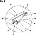
- FIG. 4 also clearly shows that the two lateral outer edges of the supporting pin-shaped holding devices 34 are provided with a continuous edge bead 48.
- the edge bead 48 has a width of approximately 3 mm and a height of approximately 1 mm. This increases the rigidity of the holding device, while a certain required elasticity is retained in order to be able to cushion the impacts from the reversal of direction when the top floor is pivoted up and down during the vibration test and to pass them on to the cross members 32 only to a lesser extent.
- the present invention thus offers, with comparatively small measures, a valuable step with regard to an increase in value through longer re-use of used IBCs.
Landscapes
- Engineering & Computer Science (AREA)
- Mechanical Engineering (AREA)
- Pallets (AREA)
- Packages (AREA)
- Auxiliary Devices For And Details Of Packaging Control (AREA)
Description
- Die Erfindung betrifft einen Palettencontainer (im Folgenden kurz als "IBC" bezeichnet) zur Lagerung und zum Transport von insbesondere gefährlichen flüssigen oder fließfähigen Füllgütern mit einem dünnwandigen starren Innenbehälter aus thermoplastischem Kunststoff, mit einem den Kunststoff-Innenbehälter als Stützmantel dicht umschließenden Rohr-Gitterrahmen aus miteinander verschweißten horizontalen und vertikalen Rohrstäben und mit einer rechteckigen Bodenpalette, auf welcher der Kunststoffbehälter aufliegt und mit welcher der Rohr-Gitterrahmen fest verbunden ist, wobei der rechteckförmige Kunststoffbehälter zwei längere Seitenwandungen, eine kürzere Rückwandung, eine kürzere Vorderwandung, einen Behälterunterboden und einen Oberboden mit zentralmittigem verschließbarem Einfüllstutzen aufweist, wobei oben im Rohr-Gitterrahmen seitlich neben dem Einfüllstutzen des Kunststoff-Innenbehälters zwei Quertraversen verlaufen, die an den beiden längeren Seitenwandungen des Rohr-Gitterrahmens befestigt sind und die mittig von zwei auf dem Oberboden angeordneten, aus dem Kunststoffmaterial des Kunststoff-Innenbehälters ausgebildeten Haltevorrichtungen übergriffen werden.
- In der chemischen Industrie werden Palettencontainer bzw. IBCs in großem Umfang vorwiegend zum Transport von flüssigen Chemikalien eingesetzt. Diese chemischen Produkte stellen zum größten Teil gefährliche flüssige Füllgüter dar, für deren Lagerung und Transport nur entsprechend bauartgeprüfte Behälter zugelassen sind. Bei der vom Bundesamt für Materialprüfung (BAM) durchgeführten Bauartprüfung müssen verschiedene Festigkeits- und Dichtheits-Kriterien erfüllt werden. Unter anderem ist für IBCs als Simulation für andauernde Transporterschütterungen ein sogenannter "Vibrationstest" auf einem Rütteltisch zu absolvieren, der in kürzester Zeit extrem hohe dynamische Rüttelbelastungen auf die befüllten Palettencontainer ausübt. Der entsprechend angetriebene Rütteltisch führt kurze vertikale Hubbewegungen mit doppelter Amplitude von 25 mm ± 5% aus, wobei die Frequenz der Hubbewegungen so zu wählen ist, dass der Palettencontainer mit seiner Bodenpalette gerade von der Auflageplatte des Rütteltisches abhebt. Die Prüfdauer beträgt eine Stunde. Danach darf der geprüfte Palettencontainer keine Undichtheit, keinen Bruch und kein Zubruchgehen/Versagen der baulichen Ausrüstung aufweisen.
- Funktionell wirkt bei jedem schlagartigen Hochfahren des Rütteltisches auf die im Innenbehälter befindliche Flüssigkeitssäule eine starke hydrodynamische Stoßwelle ein, wodurch die Flüssigkeit bestrebt ist, in die Breite auszuweichen. Dadurch werden die Seitenwandungen des umschließenden Gitterkäfigs elastisch nach außen gedrückt (in vier Richtungen). Gleichzeitig senkt sich der Oberboden mit Schraubkappe auf der zentralmittigen Einfüllöffnung stark nach unten ab. Beim nachfolgenden abrupten Herunterfahren des Rütteltisches federn die nach außen gedrückten Seitenwandungen des Gitterkäfigs zurück und die Flüssigkeit weicht nun nach oben aus (nur in eine Richtung), wobei der Oberboden mit Schraubkappe heftig nach oben ausschlägt. Durch die schnellen periodischen Wiederholungen dieser Bewegungsabläufe kann die Flüssigkeit bzw. das gesamte Behältersystem in Resonanzschwingungen geraten, wodurch sich die Größe der Ausweichbewegungen weiter erhöht und schnell kritische Werte übersteigt, die zu Rohrstabbrüchen und Aufreißen von Schweißverbindungen der verschweißten Rohrstabkreuzungen führen können.
- Palettencontainer der vorliegenden Bauart mit dünnwandigem Kunststoff-Innenbehälter und umschließendem Rohrgitterrahmen (sogenannte Composite IBCs) sind üblicherweise mit zwei rohrstabförmigen Quertraversen versehen, die seitlich neben dem Einfüllstutzen über den Oberboden des Kunststoff-Innenbehälters verlaufen und am obersten horizontal umlaufenden Rohrstab des Rohr-Gitterrahmens befestigt sind. Dies dient einerseits zur Versteifung des oberen Gitterrahmenbereichs und andererseits zur Fixierung des Kunststoff-Innenbehälters innerhalb des Rohr-Gitterrahmens. Dabei soll unter anderem verhindert werden, dass z. B. bei einem Umstürzen eines Palettencontainers der gefüllte Kunststoff-Innenbehälter aus dem Gitterkäfig herausrutscht und nicht mehr handhabbar ist.
- Aus der Druckschrift
EP 0 881 161 A1 ist ein ähnlicher Palettenbehälter mit abnehmbaren Schutzdeckel aus Metall oder Kunststoff bekannt, bei dem ein Einfallen des Oberbodens mit Einfüllstutzen des Kunststoff-Innenbehälters durch Einwirkung von äußeren oder inneren Kräften vermieden werden soll. Hier soll insbesondere einer Absenkung des Oberbodens durch Aufbau eines Unterdrucks bei Abkühlung des Füllguts entgegengewirkt werden, damit der Schraubdeckel weiterhin mittels handelsüblicher Schraubschlüssel geöffnet werden kann. Auch soll ein Absenken bei Aufsetzen eines Rührwerkzeugs auf den Einfüllstutzen vermieden werden. Dazu ist der Oberboden des Kunststoff-Innenbehälters am darüber angeordneten Schutzdeckel befestigt. Am Oberboden sind zwei Befestigungsösen angeformt, die durch Schlitze im Schutzdeckel hindurchgesteckt sind und nach oben vorstehen. Zur Fixierung des Oberbodens am Schutzdeckel sind entsprechende Splinte durch die überstehenden Befestigungsösen gesteckt. - Die heutzutage im Markt befindlichen gattungsmäßigen Palettencontainer der verschiedenen Hersteller weisen nahezu alle als Haltevorrichtungen am Oberboden angeformte geschlossene Befestigungsösen auf, die die beiden Quertraversen am oberen Gitterkäfig übergreifen.
- Diese bekannten Befestigungsösen sind jedoch vergleichsweise dünn und mit großer Durchgangsöffnung ausgebildet, weil bei der Montage der Quertraversen diese mit ihren abgewinkelten Befestigungsenden durch das Auge der Befestigungsösen hindurchgesteckt werden müssen. Das stellt demzufolge keine stabile Aufhängung des Innenbehälters für die Zulassungsprüfung für Gefahrgut, insbesondere den Vibrationstest dar.
- Aus
US 6,202,844 B1 ist ein Palettencontainer zur Lagerung und zum Transport von insbesondere gefährlichen flüssigen oder fließfähigen Füllgütern bekannt. - Der vorliegenden Erfindung liegt die Aufgabe zugrunde, die Stabilität von Palettencontainern gegen äußere Einwirkung von Schwingungsbelastungen auf einfache Weise um ein Stückchen zu erhöhen und damit insgesamt die Lebensdauer der Palettencontainer zu verlängern.
- Diese Aufgabe wird mit den speziellen Merkmalen des Patentanspruchs 1 gelöst. Die Merkmale in den Unteransprüchen beschreiben weitere vorteilhafte Ausgestaltungsmöglichkeiten des erfindungsgemäßen Palettencontainers. Die vorgeschlagene technische Lehre eröffnet auf überraschend einfache Weise eine verbesserte Widerstandsfähigkeit gegen andauernde Transporterschütterungen von befüllten Palettencontainern.
- Durch die konstruktiven Maßnahmen der vorliegenden Erfindung wird eine sich bei dynamischer Dauerbelastung erst im oberen Grenzbereich auswirkende Leistungssteigerung des gesamten Palettenbehältersystems erzielt.
- Die vorliegende Erfindung zeichnet sich in konstruktiver Weise dadurch aus, dass die Haltevorrichtungen als einseitig offene massive Tragzapfen mit einem kurzen freien Ende und einem vergleichsweise langen Anbindungsbereich ausgebildet sind. Dabei ist der vergleichsweise lange Anbindungsbereich der tragzapfenförmigen Haltevorrichtungen etwa doppelt so lang wie das kurze freie Ende ausgebildet. Hierdurch werden mehrere Vorteile gleichzeitig erzielt.
- Zum einen wird ein wesentlicher fertigungstechnischer Vorteil erzielt. Die Quertraversen müssen nicht mehr von Hand mit ihren vergleichsweise großen abgewinkelten Befestigungsenden durch eine geschlossene Befestigungsöse hindurchgesteckt werden, sondern können auf einfache Weise von der Seite her unter das kurze freie Ende des Tragzapfens geschoben werden. Dieser Vorgang kann leicht automatisiert werden. Zum anderen weist der Palettencontainer im Hinblick auf die Zulassungsprüfungen durch den Tragzapfen mit dem langen Anbindungsbereich auf dem Innenbehälteroberboden und die massive kurze Ausbildung des freien Endes des Tragzapfens eine erhöhte Steifigkeit auf. In Verbindung mit der massiven Ausbildung des freien Tragzapfenendes ist der Freiraum unterhalb des Endes zum Oberboden gerade nur so groß, dass die Quertraverse genau darunter passt bzw. den vorhandenen Freiraum ausfüllt, so dass kein überschüssiger Freiraum mehr verbleibt und kein bisher übliches freies Bewegen (Schlagen) der Quertraverse in einer großen Ösenöffnung mehr stattfinden kann. Vielmehr besteht nun eine dauerhafte Kontaktfixierung zwischen tragzapfenförmiger Haltevorrichtungen und Quertraverse bei jeder Auf- und Abbewegung des Innenbehälter-Oberbodens ohne freies Bewegen und Schlagen der Quertraverse.
- In Ausgestaltung der Erfindung ist zweckmäßigerweise vorgesehen, dass die beiden tragzapfenförmigen Haltevorrichtungen mit ihrem freien Ende aufeinander zuweisend ausgebildet sind. Dadurch wird erreicht, dass selbst bei extremen Vibrationsbelastungen im Resonanzbereich die Quertraversen nicht einfach unter den freien Enden der Tragzapfen herausspringen.
- In konstruktiver Ausgestaltung weisen die tragzapfenförmigen Haltevorrichtungen insgesamt einen rechteckförmigen Querschnitt auf, wobei die Höhe ca. 35 mm bis 45 mm - vorzugsweise 38 mm, die Länge ca. 65 mm bis 80 mm - vorzugsweise 72 mm und die Dicke ca. 5 mm bis 8 mm -vorzugsweise 6 mm beträgt. Damit sind die tragzapfenförmigen Haltevorrichtungen nahezu doppelt so lang wie hoch ausgebildet und weisen im Vergleich mit bekannten dünnen Befestigungsösen eine verbesserte Steifigkeit auf. Dies wird auch dadurch bewirkt, dass das kurze freie Ende eine Länge von "nur" ca. 18 mm bis 25 mm - vorzugsweise 22 mm - und eine freie Höhe bzw. einen geringen Abstand zum Oberboden des Innenbehälters von ca. 15 mm bis 20 mm - vorzugsweise 17 mm - aufweist.
- In weiterer konstruktiver Ausgestaltung ist vorgesehen, dass der Anbindungsbereich der tragzapfenförmigen Haltevorrichtungen ausschließlich im schräg verlaufenden Übergangsbereich des Innenbehälters ausgebildet ist. Durch die Anordnung des langen Anbindungsbereichs der massiven Tragzapfen im schräg verlaufenden Übergangsbereich des Innenbehälters von den beiden höher gelegenen Außenteilen zum tiefer gelegten Mittelteil (zur geschützten Anordnung des Einfüll-Schraubdeckels) wird eine Verminderung der Spitzenwerte der Auf- und Abbewegung des Innenbehälteroberbodens bewirkt, was letztendlich zu einer spürbaren Erhöhung der Widerstandsfähigkeit bei lang andauernder Schwingungsbelastung führt.
- Die Erfindung wird nachfolgend anhand eines in den Zeichnungen schematisch dargestellten Ausführungsbeispiels näher erläutert und beschrieben.
- Es zeigen:
- Figur 1:
- einen erfindungsgemäßen IBC in perspektivischer Schrägansicht,
- Figur 2:
- einen Kunststoff-Innenbehälter in Seitenansicht,
- Figur 3:
- den Detail-Ausschnitt aus
Fig. 2 mit tragzapfenförmiger Haltevorrichtung und - Figur 4:
- eine perspektivische Schrägansicht der Haltevorrichtung gem.
Fig. 3 - In
Figur 1 ist mit der Bezugsziffer 10 ein erfindungsgemäßer Palettencontainer (= IBC) zur Lagerung und zum Transport von insbesondere gefährlichen flüssigen oder fließfähigen Füllgütern bezeichnet. Für einen Einsatz bzw. für eine Verwendung von gefährlichen Füllgütern erfüllt der Palettencontainer 10 besondere Prüfkriterien und ist mit einer entsprechenden amtlichen Gefahrgut-Zulassung versehen. In einer Ausführung für ein Füllgutvolumen von ca. 1000 I weist der Palettencontainer 10 standardisierte Abmessungen mit einer Länge von ca. 1200 mm, einer Breite von ca. 1000 mm und einer Höhe von ca. 1151 mm auf. Die Hauptelemente des Palettencontainers 10 bestehen aus einem im Blasformverfahren aus thermoplastischem Kunststoff hergestellten, dünnwandigen starren Innenbehälter 12, einem den Kunststoff-Innenbehälter 12 als Stützmantel dicht umschließenden Rohr-Gitterrahmen 14 und einer Bodenpalette 16, auf welcher der Kunststoff-Innenbehälter 12 aufliegt und mit welcher der Rohr-Gitterrahmen 14 fest verbunden ist. Der äußere Rohr-Gitterrahmen 14 besteht aus miteinander verschweißten horizontalen und vertikalen Rohrstäben 18, 20. Um einen geschlossenen Gitterkäfig als Außenbehälter zu erhalten, sind die ringförmig umlaufenden horizontalen Rohrstäbe 18 jeweils an einer Verbindungsstelle fest miteinander verbunden. Die Bodenpalette 16 ist in der dargestellten Version als Composite-Palette mit oberer Stahlblech-Tragplatte, mit darunter angeordnetem Stahlrohr-Tragrahmen und mit Kunststoff-Eck- und Mittelfüßen ausgebildet. Auf der Frontseite des Rohr-Gitterrahmens 14 ist eine Beschriftungstafel 22 aus dünnem Stahlblech zur Kennzeichnung des jeweiligen flüssigen Füllguts befestigt. In der Mitte des Bodens des Kunststoff-Innenbehälters 12 ist zur Entnahme des flüssigen Füllguts ein Entnahmestutzen 24 für den Anschluss einer Entnahmearmatur ausgebildet. - Entsprechend den Abmessungen des Palettencontainers 10 weist der Kunststoff-Innenbehälter 12 zwei längere Seitenwandungen, eine kürzere Rückwandung, eine kürzere Vorderwandung, einen Behälterunterboden und einen Oberboden 26 mit zentralmittig angeordnetem mittels Schraubdeckel 28 verschließbarem Einfüllstutzen 30 auf, wobei oben im Rohr-Gitterrahmen 14 seitlich neben dem Einfüllstutzen 30 des Kunststoff-Innenbehälters 12 zwei rohrstabförmige Quertraversen 32 verlaufen, die an den beiden längeren Seitenwandungen des Rohr-Gitterrahmens 14 befestigt sind und die mittig von zwei auf dem Oberboden 26 angeordneten, aus dem Kunststoffmaterial des Kunststoff-Innenbehälters 12 ausgebildeten massiven tragzapfenförmigen Haltevorrichtungen 34 übergriffen werden.
- Der kubusförmige Kunststoff-Innenbehälter 12 ist in
Figur 2 in Seitenansicht für sich (ohne den umschließenden Rohr-Gitterrahmen 14) dargestellt. Der bodenseitige Entnahmestutzen 24 ist auf einer kürzeren hier nicht ersichtlichen Seitenwandung angeordnet. Der obere zentralmittig angeordnete Einfüllstutzen 30 ist in einem tiefer gelegten Mittelteil 36 des Innenbehälters 12 zwischen zwei höher gelegenen Außenteilen 38 positioniert. In den schräg ausgebildeten Übergangsbereichen 40 vom tiefer gelegten Mittelteil 36 zu den beiden höher gelegenen Außenteilen 38 sind die beiden massiven, einseitig offenen tragzapfenförmigen Haltevorrichtungen 34 angeordnet. - Die Haltevorrichtungen 34 werden während des Blasformvorganges beim Schließen der Blasform im Bereich der Quetschnaht in dafür ausgeformten Vertiefungen aus den abgequetschten Schlauchenden ausgeformt. Bei den bisher üblichen geschlossenen Befestigungsösen musste nach jedem Blasformvorgang das Kunststoffmaterial in den Ösenöffnungen separat ausgeschnitten werden. Dieser zusätzliche Arbeitsschritt entfällt in vorteilhafter Weise bei den erfindungsgemäßen einseitig offenen tragzapfenförmigen Haltevorrichtungen 34.
- Die in
Figur 3 vergrößerte Darstellung macht deutlich, dass die Haltevorrichtungen 34 als einseitig offene massive Tragzapfen mit einem kurzen freien Ende 42 und einem vergleichsweise langen Anbindungsbereich 44 ausgebildet sind. In den vorherigen DarstellungenFig. 1 undFig. 2 war erkennbar, dass die Haltevorrichtungen 34 mit ihrem freien Ende 42 aufeinander zuweisend ausgebildet sind. - Gemäß konstruktiver Ausgestaltung ist der vergleichsweise lange Anbindungsbereich 44 der tragzapfenförmigen Haltevorrichtungen 34 etwa doppelt so lang wie das kurze freie Ende 42 ausgebildet. Dabei weisen die Haltevorrichtungen 34 insgesamt einen rechteckförmigen Querschnitt auf, wobei die Höhe ca. 35 mm bis 45 mm - vorzugsweise 38 mm -, die Länge ca. 65 mm bis 80 mm - vorzugsweise 72 mm - und die Dicke ca. 5 mm bis 8 mm - vorzugsweise 6 mm - beträgt. Die tragzapfenförmigen Haltevorrichtungen 34 sind damit nahezu doppelt so lang wie hoch. Die kontaktgebundene Einklemmung der Quertraversen (ohne Freiraum wie in einer geschlossenen Durchstecköse) erfolgt dadurch, dass das kurze freie Ende 42 eine Länge von ca. 18 mm bis 25 mm - vorzugsweise 22 mm - und eine freie Höhe bzw. einen Abstand zum Oberboden 26 des Innenbehälters von ca. 15 mm bis 20 mm - vorzugsweise 17 mm - aufweist.
- Wie in
Figur 3 weiterhin deutlich erkennen lässt, ist der Anbindungsbereich 44 der tragzapfenförmigen Haltevorrichtungen 34 ausschließlich in den schräg verlaufenden Übergangsbereichen 40 des Innenbehälter-Oberbodens 26 ausgebildet. Um ein Herausspringen der Quertraversen 32 unter den Haltevorrichtungen 34 völlig auszuschließen sind die beiden Haltevorrichtungen 34 an ihrem freien Ende 42 mit einer kleinen nach unten weisenden Nase 46 versehen. - Die perspektivische Ansicht in
Figur 4 zeigt zudem deutlich, dass die beiden seitlichen Außenkanten der tragzapfenförmigen Haltevorrichtungen 34 mit einem durchgängigen Randwulst 48 versehen sind. - Der Randwulst 48 weist eine Breite von ca. 3 mm und eine Höhe von ca. 1 mm auf. Dies erhöht die Steifigkeit der Haltevorrichtung, wobei eine gewisse erforderliche Elastizität erhalten bleibt, um die Stöße aus der Richtungsumkehrung beim Auf- und Abschwenken des Oberbodens während des Vibrationstests abfedern zu können und nur in vermindertem Maße an die Quertraversen 32 weiterzuleiten.
- Bei Vergleichsversuchen von Vibrationstests mit Videoaufzeichnung ist bei einem Standard-IBC mit bekannter geschlossener Öse mit großer Durchgangsöffnung erkennbar, dass der Oberboden mit der dünnen Öse insgesamt mit höherer Schwingungsamplitude und dadurch mit mehr Wucht auf den Querträger schlägt, weil beim Hochbewegen des Oberbodens die dünne Öse von der Querträger-Stange abhebt und beim Herabbewegen schockartig auf den Querträger trifft, während die offene Haltevorrichtung auch noch im oberen Wendepunkt des Oberbodens auf der Querträger-Stange aufliegt und nicht abhebt. Dadurch wird das vertikale "Pulsieren" in den beiden höher positionierten äußeren Seitenbereichen bzw. Außenteilen des Oberbodens spürbar vermindert und die Schwingungsamplitude des horizontalen "Pulsierens" im Bereich der beiden gegenüberliegenden längeren Seitenwandungen des Gitterkäfigs bzw. des Palettencontainers 10 reduziert. So haben Messungen der maximalen elastischen Auslenkung der gegenüberliegenden längeren Seitenwandungen des Gitterkäfigs bei dynamischer Belastung ergeben, dass bei der kontaktgebundenen formschlüssigen Aufhängung des Innenbehälter-Oberbodens 26 mittels der einseitig offenen massiven tragzapfenförmigen Haltevorrichtungen 34 an den Quertraversen 32 eine um ca. 20 % geringere Gitterauslenkung erfolgt. Hierdurch ergeben sich ersichtlich geringere Spitzenwerte von kritischen Wechsel-Biegespannungen und schädlichen Zugspannungen auf die empfindlichen Schweißpunkte der verschweißten Rohrkreuzungen im Gitterkäfig. Dies begründet eine längere Lebensdauer und Gebrauchsfähigkeit der erfindungsgemäßen Palettencontainer.
- Die vorliegende Erfindung bietet somit mit vergleichsweise kleinen Maßnahmen einen wertvollen Schritt in Hinblick auf eine Wertsteigerung durch längere Wiederverwendung von gebrauchten IBCs.
-
- 10
- Palettencontainer
- 12
- Kunststoff-Innenbehälter
- 14
- Rohr-Gitterrahmen
- 16
- Bodenpalette
- 18
- horizontale Rohrstäbe (12)
- 20
- vertikale Rohrstäbe (12)
- 22
- Beschriftungstafel
- 24
- unterer Entnahmestutzen
- 26
- Oberboden (12)
- 28
- Schraubdeckel (30)
- 30
- oberer Einfüllstutzen (26)
- 32
- Quertraverse (14)
- 34
- tragzapfenförmige Haltevorrichtung (26)
- 36
- Mittelteil (26, 12)
- 38
- Außenteil (26, 12)
- 40
- Übergangsbereich (36-38)
- 42
- freies Ende (34)
- 44
- Anbindungsbereich (34)
- 46
- kleine Nase (42)
- 48
- Randwulst (34)
Claims (9)
- Palettencontainer (10) zur Lagerung und zum Transport von insbesondere gefährlichen flüssigen oder fließfähigen Füllgütern mit einem dünnwandigen starren Innenbehälter (12) aus thermoplastischem Kunststoff, mit einem den Kunststoff-Innenbehälter (12) als Stützmantel dicht umschließenden Rohr-Gitterrahmen (14) aus miteinander verschweißten horizontalen und vertikalen Rohrstäben (18, 20), und mit einer rechteckigen Bodenpalette (16), auf welcher der Kunststoff-Innenbehälter (12) aufliegt und mit welcher der Rohr-Gitterrahmen (14) fest verbunden ist, wobei der kubusförmige Kunststoff-Innenbehälter (12) zwei längere Seitenwandungen, eine kürzere Rückwandung, eine kürzere Vorderwandung, einen Behälterunterboden und einen Oberboden (26) mit zentralmittig angeordnetem mittels Schraubdeckel (28) verschließbarem Einfüllstutzen (30) aufweist, wobei oben im Rohr-Gitterrahmen (14) seitlich neben dem Einfüllstutzen (30) des Kunststoff-Innenbehälters (12) zwei rohrstabförmige Quertraversen (32) verlaufen, die an den beiden längeren Seitenwandungen des Rohr-Gitterrahmens (14) befestigt sind und die mittig von zwei auf dem Oberboden (26) angeordneten, aus dem Kunststoffmaterial des Kunststoff-Innenbehälters (12) ausgebildeten Haltevorrichtungen (34) übergriffen werden.
dadurch gekennzeichnet, dass
die Haltevorrichtungen (34) als einseitig offene massive Tragzapfen, mit einem kurzen freien Ende (42) und einem vergleichsweise langen Anbindungsbereich (44) ausgebildet sind. - Palettencontainer nach Anspruch 1,
dadurch gekennzeichnet, dass
die Haltevorrichtungen (34) mit ihrem freien Ende (42) aufeinander zuweisend ausgebildet sind. - Palettencontainer nach Anspruch 1 oder 2,
dadurch gekennzeichnet, dass
der vergleichsweise lange Anbindungsbereich (44) der Haltevorrichtungen (34) etwa doppelt so lang wie das kurze freie Ende (42) ausgebildet ist. - Palettencontainer nach Anspruch 1 oder 2,
dadurch gekennzeichnet, dass die Haltevorrichtungen (34) insgesamt einen rechteckförmigen Querschnitt aufweisen, wobei die Höhe ca. 35 mm bis 45 mm die Länge ca. 65 mm bis 80 mm und die Dicke ca. 5 mm bis 8 mm beträgt. - Palettencontainer nach Anspruch 1, 2, 3 oder 4,
dadurch gekennzeichnet, dass
das kurze freie Ende (42) eine Länge von ca. 18 mm bis 25 mm und eine freie Höhe bzw. einen Abstand zum Oberboden (26) des Innenbehälters (12) von ca. 15 mm bis 20 mm aufweist. - Palettencontainer nach Anspruch 1, 2, 3, 4 oder 5,
dadurch gekennzeichnet, dass
der Anbindungsbereich (44) der Haltevorrichtungen (34) ausschließlich im schräg verlaufenden Übergangsbereich (40) des Innenbehälter-Oberbodens (26) ausgebildet ist. - Palettencontainer nach einem der vorhergehenden Ansprüche 1 bis 6,
dadurch gekennzeichnet, dass
die Haltevorrichtungen (34) an ihrem freien Ende (42) mit einer kleinen nach unten weisenden Nase (46) versehen sind. - Palettencontainer nach einem der vorhergehenden Ansprüche 1 bis 7,
dadurch gekennzeichnet, dass
die beiden seitlichen Außenkanten der Haltevorrichtungen (34) mit einem durchgängigen Randwulst (48) versehen sind. - Palettencontainer nach Anspruch 8,
dadurch gekennzeichnet, dass
der Randwulst (48) eine Breite von ca. 3 mm und eine Höhe von ca. 1 mm aufweist.
Priority Applications (2)
| Application Number | Priority Date | Filing Date | Title |
|---|---|---|---|
| PL17767995T PL3509963T3 (pl) | 2016-09-12 | 2017-09-12 | Kontener na palety |
| HRP20211522TT HRP20211522T1 (hr) | 2016-09-12 | 2017-09-12 | Paletni spremnik |
Applications Claiming Priority (2)
| Application Number | Priority Date | Filing Date | Title |
|---|---|---|---|
| DE202016005519 | 2016-09-12 | ||
| PCT/EP2017/001074 WO2018046131A1 (de) | 2016-09-12 | 2017-09-12 | Palettencontainer |
Publications (2)
| Publication Number | Publication Date |
|---|---|
| EP3509963A1 EP3509963A1 (de) | 2019-07-17 |
| EP3509963B1 true EP3509963B1 (de) | 2021-07-14 |
Family
ID=59887186
Family Applications (1)
| Application Number | Title | Priority Date | Filing Date |
|---|---|---|---|
| EP17767995.8A Active EP3509963B1 (de) | 2016-09-12 | 2017-09-12 | Palettencontainer |
Country Status (21)
| Country | Link |
|---|---|
| US (1) | US11078002B2 (de) |
| EP (1) | EP3509963B1 (de) |
| JP (1) | JP7004701B2 (de) |
| KR (1) | KR20190047009A (de) |
| CN (1) | CN109689525B (de) |
| AU (1) | AU2017323233B2 (de) |
| BR (1) | BR112019004730B1 (de) |
| CA (1) | CA3036355A1 (de) |
| DK (1) | DK3509963T3 (de) |
| ES (1) | ES2891786T3 (de) |
| HR (1) | HRP20211522T1 (de) |
| HU (1) | HUE056012T2 (de) |
| IL (1) | IL265077B (de) |
| MX (1) | MX2019002674A (de) |
| MY (1) | MY202803A (de) |
| PL (1) | PL3509963T3 (de) |
| PT (1) | PT3509963T (de) |
| RU (1) | RU2744871C2 (de) |
| SG (1) | SG11201901924WA (de) |
| WO (1) | WO2018046131A1 (de) |
| ZA (1) | ZA201901215B (de) |
Families Citing this family (8)
| Publication number | Priority date | Publication date | Assignee | Title |
|---|---|---|---|---|
| HUE039844T2 (hu) * | 2016-05-12 | 2019-02-28 | Hewlett Packard Development Co | Építõanyag-tároló |
| EP3741709B1 (de) * | 2019-05-23 | 2021-12-22 | Maschio N.S. S.R.L. | Tafel für einen gittermantel aus metall für einen flüssigkeitsbehälter |
| PL4045429T3 (pl) * | 2019-10-18 | 2023-11-06 | Mauser-Werke Gmbh | Paletowany kontener |
| DE102019007360A1 (de) * | 2019-10-23 | 2021-04-29 | Mauser-Werke Gmbh | Palettencontainer |
| CN110980011B (zh) * | 2020-01-02 | 2022-02-01 | 中车长江车辆有限公司 | 一种蓄能管支撑结构和集装箱 |
| WO2022182557A1 (en) * | 2021-02-23 | 2022-09-01 | Monsanto Technology Llc | Packaging assemblies for product components, and related methods |
| USD979241S1 (en) | 2021-02-23 | 2023-02-28 | Monsanto Technology Llc | Caged co-pack container |
| US12037221B2 (en) * | 2021-06-30 | 2024-07-16 | Mark Ostberg | Hoist cage assembly |
Family Cites Families (19)
| Publication number | Priority date | Publication date | Assignee | Title |
|---|---|---|---|---|
| SE405589B (sv) | 1975-07-30 | 1978-12-18 | Schuetz Udo | Lastpallsbehallare |
| JPS5612089U (de) * | 1979-07-10 | 1981-02-02 | ||
| DE19511723C1 (de) * | 1995-03-30 | 1996-08-29 | Protechna Sa | Palettenbehälter |
| DE29510064U1 (de) * | 1995-06-26 | 1995-08-03 | Schütz-Werke GmbH & Co KG, 56242 Selters | Transport- und Lagerbehälter für Flüssigkeiten |
| BR9713209A (pt) * | 1996-09-19 | 2000-04-04 | Roth Werke Gmbh | Receptáculo para pallets |
| DE19722194C2 (de) * | 1997-05-27 | 1999-03-18 | Protechna Sa | Transport- und Lagerbehälter für Flüssigkeiten |
| DE19838309A1 (de) * | 1998-08-24 | 2000-03-02 | Roth Werke Gmbh | Behälter |
| ES2251354T5 (es) * | 2000-05-15 | 2010-04-05 | Daviplast - Servicos De Consultoria, Sociedade Unipessoal Lda. | Paleta con plataforma de plastico. |
| JP2002211875A (ja) | 2001-01-19 | 2002-07-31 | Waitekku Kk | ラック装置 |
| DE20206652U1 (de) * | 2002-04-25 | 2002-08-08 | Protechna S.A., Freiburg/Fribourg | Transport- und Lagerbehälter für Flüssigkeiten |
| ES2340625T3 (es) | 2007-04-18 | 2010-06-07 | Daviplast - Servicos De Consultoria, Sociedade Unipessoal Lda. | Recipiente pallet. |
| DE102007044279B4 (de) * | 2007-09-17 | 2013-06-20 | Ekkehard Schneider | Anordnung zum Lagern und/oder Transportieren |
| DE102008027337A1 (de) | 2008-02-27 | 2009-09-17 | Protechna S.A. | Transport- und Lagerbehälter für Flüssigkeiten |
| DE102009036487B4 (de) | 2009-08-07 | 2011-09-15 | Ekkehard Schneider | Behälteranordnung mit dreieckig ausgebildetem Versteifungsteil |
| EP2301860B1 (de) * | 2009-09-29 | 2013-05-29 | Greif International Holding BV. | Palettenbehälter für Flüssigkeiten |
| DE102010040270A1 (de) * | 2010-09-06 | 2012-03-08 | Protechna S.A. | Transport- und Lagerbehälter für Flüssigkeiten |
| WO2012085940A2 (en) | 2010-12-24 | 2012-06-28 | Genex Science And Technologies Pvt. Ltd. | Pallet container with riveted cage |
| DE102011075266A1 (de) * | 2011-05-04 | 2012-11-08 | Protechna S.A. | Kufenpalette, insbesondere für Transport- und Lagerbehälter für Flüssigkeiten |
| DE202013000624U1 (de) * | 2012-09-21 | 2013-03-07 | Mauser-Werke Gmbh | Palettencontainer |
-
2017
- 2017-09-12 HR HRP20211522TT patent/HRP20211522T1/hr unknown
- 2017-09-12 CN CN201780055952.5A patent/CN109689525B/zh active Active
- 2017-09-12 JP JP2019513767A patent/JP7004701B2/ja active Active
- 2017-09-12 HU HUE17767995A patent/HUE056012T2/hu unknown
- 2017-09-12 ES ES17767995T patent/ES2891786T3/es active Active
- 2017-09-12 BR BR112019004730-1A patent/BR112019004730B1/pt active IP Right Grant
- 2017-09-12 WO PCT/EP2017/001074 patent/WO2018046131A1/de not_active Ceased
- 2017-09-12 CA CA3036355A patent/CA3036355A1/en active Pending
- 2017-09-12 AU AU2017323233A patent/AU2017323233B2/en not_active Ceased
- 2017-09-12 MY MYPI2019001046A patent/MY202803A/en unknown
- 2017-09-12 PT PT177679958T patent/PT3509963T/pt unknown
- 2017-09-12 DK DK17767995.8T patent/DK3509963T3/da active
- 2017-09-12 EP EP17767995.8A patent/EP3509963B1/de active Active
- 2017-09-12 KR KR1020197010345A patent/KR20190047009A/ko not_active Abandoned
- 2017-09-12 US US16/329,386 patent/US11078002B2/en active Active
- 2017-09-12 SG SG11201901924WA patent/SG11201901924WA/en unknown
- 2017-09-12 MX MX2019002674A patent/MX2019002674A/es unknown
- 2017-09-12 RU RU2019110823A patent/RU2744871C2/ru active
- 2017-09-12 PL PL17767995T patent/PL3509963T3/pl unknown
-
2019
- 2019-02-26 ZA ZA2019/01215A patent/ZA201901215B/en unknown
- 2019-02-27 IL IL265077A patent/IL265077B/en unknown
Non-Patent Citations (1)
| Title |
|---|
| None * |
Also Published As
| Publication number | Publication date |
|---|---|
| US11078002B2 (en) | 2021-08-03 |
| JP2019531234A (ja) | 2019-10-31 |
| ES2891786T3 (es) | 2022-01-31 |
| IL265077B (en) | 2022-06-01 |
| RU2019110823A3 (de) | 2020-10-28 |
| RU2744871C2 (ru) | 2021-03-16 |
| HUE056012T2 (hu) | 2022-01-28 |
| BR112019004730B1 (pt) | 2023-02-14 |
| MX2019002674A (es) | 2019-07-04 |
| BR112019004730A2 (pt) | 2019-05-28 |
| ZA201901215B (en) | 2021-08-25 |
| AU2017323233A1 (en) | 2019-04-11 |
| JP7004701B2 (ja) | 2022-01-21 |
| DK3509963T3 (da) | 2021-10-11 |
| CN109689525A (zh) | 2019-04-26 |
| PL3509963T3 (pl) | 2021-12-20 |
| MY202803A (en) | 2024-05-22 |
| KR20190047009A (ko) | 2019-05-07 |
| CN109689525B (zh) | 2020-12-04 |
| HRP20211522T1 (hr) | 2021-12-24 |
| WO2018046131A1 (de) | 2018-03-15 |
| RU2019110823A (ru) | 2020-10-12 |
| IL265077A (en) | 2019-05-30 |
| PT3509963T (pt) | 2021-09-29 |
| AU2017323233B2 (en) | 2023-04-20 |
| SG11201901924WA (en) | 2019-04-29 |
| CA3036355A1 (en) | 2018-03-15 |
| US20190225400A1 (en) | 2019-07-25 |
| EP3509963A1 (de) | 2019-07-17 |
Similar Documents
| Publication | Publication Date | Title |
|---|---|---|
| EP3509963B1 (de) | Palettencontainer | |
| DE4328009C2 (de) | Palettencontainer | |
| EP3209164B1 (de) | Lagerregal | |
| EP1343703B1 (de) | Palettencontainer | |
| EP2426067B1 (de) | Transport- und Lagerbehälter für Flüssigkeiten | |
| WO2010037546A1 (de) | Palettencontainer | |
| DE10103656A1 (de) | Palettencontainer | |
| EP4045430B1 (de) | Palettencontainer | |
| EP0585453B1 (de) | Palettencontainer | |
| DE102016010889B4 (de) | Palettencontainer | |
| EP1289853A2 (de) | Palettencontainer | |
| WO2002034642A1 (de) | Palettencontainer | |
| DE4233141A1 (de) | Transportsicherung und Versandverpackung | |
| WO2018146115A1 (de) | Doppelfass für gefahrengüter | |
| DE60317138T3 (de) | Schüttgut-Zwischenbehälter mit geringer Höhe | |
| DE2312477A1 (de) | Fuss zum abstuetzen einer leiste einer palette | |
| DE102019008477B4 (de) | Palettencontainer | |
| WO2016128248A1 (de) | Palettenartiges untergestell für transport- und lagerbehälter für flüssigkeiten | |
| EP4192751B1 (de) | Kunststoffbehälter | |
| DE4016167A1 (de) | Palettenbehaelter | |
| DE19646608A1 (de) | Mehrweg-Transportpackung für technische Geräte | |
| DE2657787B2 (de) | Lade- und Transportpalette | |
| DE202009005424U1 (de) | Transportanordnung für Zaun- und/oder Absperrelemente | |
| DE102008032807A1 (de) | Aufnahme- und Lagervorrichtung für einen zylindrischen Körper, insbesondere für eine Kabeltrommel | |
| EP3834662A1 (de) | Zweiteiliger fachboden sowie zugehöriges regal |
Legal Events
| Date | Code | Title | Description |
|---|---|---|---|
| REG | Reference to a national code |
Ref country code: HR Ref legal event code: TUEP Ref document number: P20211522T Country of ref document: HR |
|
| STAA | Information on the status of an ep patent application or granted ep patent |
Free format text: STATUS: UNKNOWN |
|
| STAA | Information on the status of an ep patent application or granted ep patent |
Free format text: STATUS: THE INTERNATIONAL PUBLICATION HAS BEEN MADE |
|
| PUAI | Public reference made under article 153(3) epc to a published international application that has entered the european phase |
Free format text: ORIGINAL CODE: 0009012 |
|
| STAA | Information on the status of an ep patent application or granted ep patent |
Free format text: STATUS: REQUEST FOR EXAMINATION WAS MADE |
|
| 17P | Request for examination filed |
Effective date: 20190412 |
|
| AK | Designated contracting states |
Kind code of ref document: A1 Designated state(s): AL AT BE BG CH CY CZ DE DK EE ES FI FR GB GR HR HU IE IS IT LI LT LU LV MC MK MT NL NO PL PT RO RS SE SI SK SM TR |
|
| AX | Request for extension of the european patent |
Extension state: BA ME |
|
| DAV | Request for validation of the european patent (deleted) | ||
| DAX | Request for extension of the european patent (deleted) | ||
| GRAP | Despatch of communication of intention to grant a patent |
Free format text: ORIGINAL CODE: EPIDOSNIGR1 |
|
| STAA | Information on the status of an ep patent application or granted ep patent |
Free format text: STATUS: GRANT OF PATENT IS INTENDED |
|
| INTG | Intention to grant announced |
Effective date: 20201123 |
|
| GRAS | Grant fee paid |
Free format text: ORIGINAL CODE: EPIDOSNIGR3 |
|
| GRAA | (expected) grant |
Free format text: ORIGINAL CODE: 0009210 |
|
| STAA | Information on the status of an ep patent application or granted ep patent |
Free format text: STATUS: THE PATENT HAS BEEN GRANTED |
|
| AK | Designated contracting states |
Kind code of ref document: B1 Designated state(s): AL AT BE BG CH CY CZ DE DK EE ES FI FR GB GR HR HU IE IS IT LI LT LU LV MC MK MT NL NO PL PT RO RS SE SI SK SM TR |
|
| REG | Reference to a national code |
Ref country code: GB Ref legal event code: FG4D Free format text: NOT ENGLISH |
|
| REG | Reference to a national code |
Ref country code: DE Ref legal event code: R096 Ref document number: 502017010910 Country of ref document: DE |
|
| REG | Reference to a national code |
Ref country code: IE Ref legal event code: FG4D Free format text: LANGUAGE OF EP DOCUMENT: GERMAN |
|
| REG | Reference to a national code |
Ref country code: AT Ref legal event code: REF Ref document number: 1410489 Country of ref document: AT Kind code of ref document: T Effective date: 20210815 |
|
| REG | Reference to a national code |
Ref country code: PT Ref legal event code: SC4A Ref document number: 3509963 Country of ref document: PT Date of ref document: 20210929 Kind code of ref document: T Free format text: AVAILABILITY OF NATIONAL TRANSLATION Effective date: 20210924 |
|
| REG | Reference to a national code |
Ref country code: DK Ref legal event code: T3 Effective date: 20211004 Ref country code: NO Ref legal event code: T2 Effective date: 20210714 |
|
| REG | Reference to a national code |
Ref country code: FI Ref legal event code: FGE |
|
| REG | Reference to a national code |
Ref country code: SE Ref legal event code: TRGR |
|
| REG | Reference to a national code |
Ref country code: NL Ref legal event code: FP |
|
| REG | Reference to a national code |
Ref country code: LT Ref legal event code: MG9D |
|
| REG | Reference to a national code |
Ref country code: SK Ref legal event code: T3 Ref document number: E 38237 Country of ref document: SK |
|
| REG | Reference to a national code |
Ref country code: GR Ref legal event code: EP Ref document number: 20210402735 Country of ref document: GR Effective date: 20211111 |
|
| REG | Reference to a national code |
Ref country code: HR Ref legal event code: ODRP Ref document number: P20211522T Country of ref document: HR Payment date: 20210929 Year of fee payment: 5 |
|
| REG | Reference to a national code |
Ref country code: HR Ref legal event code: T1PR Ref document number: P20211522 Country of ref document: HR |
|
| REG | Reference to a national code |
Ref country code: HU Ref legal event code: AG4A Ref document number: E056012 Country of ref document: HU |
|
| PG25 | Lapsed in a contracting state [announced via postgrant information from national office to epo] |
Ref country code: LT Free format text: LAPSE BECAUSE OF FAILURE TO SUBMIT A TRANSLATION OF THE DESCRIPTION OR TO PAY THE FEE WITHIN THE PRESCRIBED TIME-LIMIT Effective date: 20210714 Ref country code: RS Free format text: LAPSE BECAUSE OF FAILURE TO SUBMIT A TRANSLATION OF THE DESCRIPTION OR TO PAY THE FEE WITHIN THE PRESCRIBED TIME-LIMIT Effective date: 20210714 |
|
| REG | Reference to a national code |
Ref country code: ES Ref legal event code: FG2A Ref document number: 2891786 Country of ref document: ES Kind code of ref document: T3 Effective date: 20220131 |
|
| PG25 | Lapsed in a contracting state [announced via postgrant information from national office to epo] |
Ref country code: LV Free format text: LAPSE BECAUSE OF FAILURE TO SUBMIT A TRANSLATION OF THE DESCRIPTION OR TO PAY THE FEE WITHIN THE PRESCRIBED TIME-LIMIT Effective date: 20210714 |
|
| REG | Reference to a national code |
Ref country code: DE Ref legal event code: R097 Ref document number: 502017010910 Country of ref document: DE |
|
| PLBE | No opposition filed within time limit |
Free format text: ORIGINAL CODE: 0009261 |
|
| STAA | Information on the status of an ep patent application or granted ep patent |
Free format text: STATUS: NO OPPOSITION FILED WITHIN TIME LIMIT |
|
| PG25 | Lapsed in a contracting state [announced via postgrant information from national office to epo] |
Ref country code: SM Free format text: LAPSE BECAUSE OF FAILURE TO SUBMIT A TRANSLATION OF THE DESCRIPTION OR TO PAY THE FEE WITHIN THE PRESCRIBED TIME-LIMIT Effective date: 20210714 Ref country code: RO Free format text: LAPSE BECAUSE OF FAILURE TO SUBMIT A TRANSLATION OF THE DESCRIPTION OR TO PAY THE FEE WITHIN THE PRESCRIBED TIME-LIMIT Effective date: 20210714 Ref country code: MC Free format text: LAPSE BECAUSE OF FAILURE TO SUBMIT A TRANSLATION OF THE DESCRIPTION OR TO PAY THE FEE WITHIN THE PRESCRIBED TIME-LIMIT Effective date: 20210714 Ref country code: EE Free format text: LAPSE BECAUSE OF FAILURE TO SUBMIT A TRANSLATION OF THE DESCRIPTION OR TO PAY THE FEE WITHIN THE PRESCRIBED TIME-LIMIT Effective date: 20210714 Ref country code: AL Free format text: LAPSE BECAUSE OF FAILURE TO SUBMIT A TRANSLATION OF THE DESCRIPTION OR TO PAY THE FEE WITHIN THE PRESCRIBED TIME-LIMIT Effective date: 20210714 |
|
| 26N | No opposition filed |
Effective date: 20220419 |
|
| REG | Reference to a national code |
Ref country code: HR Ref legal event code: ODRP Ref document number: P20211522 Country of ref document: HR Payment date: 20220826 Year of fee payment: 6 |
|
| PG25 | Lapsed in a contracting state [announced via postgrant information from national office to epo] |
Ref country code: CY Free format text: LAPSE BECAUSE OF FAILURE TO SUBMIT A TRANSLATION OF THE DESCRIPTION OR TO PAY THE FEE WITHIN THE PRESCRIBED TIME-LIMIT Effective date: 20210714 |
|
| P01 | Opt-out of the competence of the unified patent court (upc) registered |
Effective date: 20230529 |
|
| REG | Reference to a national code |
Ref country code: HR Ref legal event code: ODRP Ref document number: P20211522 Country of ref document: HR Payment date: 20230904 Year of fee payment: 7 |
|
| PG25 | Lapsed in a contracting state [announced via postgrant information from national office to epo] |
Ref country code: MK Free format text: LAPSE BECAUSE OF FAILURE TO SUBMIT A TRANSLATION OF THE DESCRIPTION OR TO PAY THE FEE WITHIN THE PRESCRIBED TIME-LIMIT Effective date: 20210714 |
|
| REG | Reference to a national code |
Ref country code: HR Ref legal event code: ODRP Ref document number: P20211522 Country of ref document: HR Payment date: 20240905 Year of fee payment: 8 |
|
| PG25 | Lapsed in a contracting state [announced via postgrant information from national office to epo] |
Ref country code: MT Free format text: LAPSE BECAUSE OF FAILURE TO SUBMIT A TRANSLATION OF THE DESCRIPTION OR TO PAY THE FEE WITHIN THE PRESCRIBED TIME-LIMIT Effective date: 20210714 |
|
| PGFP | Annual fee paid to national office [announced via postgrant information from national office to epo] |
Ref country code: BG Payment date: 20240926 Year of fee payment: 8 |
|
| PGFP | Annual fee paid to national office [announced via postgrant information from national office to epo] |
Ref country code: IE Payment date: 20240905 Year of fee payment: 8 Ref country code: HR Payment date: 20240905 Year of fee payment: 8 Ref country code: FI Payment date: 20240905 Year of fee payment: 8 |
|
| PGFP | Annual fee paid to national office [announced via postgrant information from national office to epo] |
Ref country code: GR Payment date: 20240910 Year of fee payment: 8 Ref country code: DK Payment date: 20240905 Year of fee payment: 8 |
|
| PGFP | Annual fee paid to national office [announced via postgrant information from national office to epo] |
Ref country code: PT Payment date: 20240904 Year of fee payment: 8 |
|
| PGFP | Annual fee paid to national office [announced via postgrant information from national office to epo] |
Ref country code: LU Payment date: 20240910 Year of fee payment: 8 Ref country code: BE Payment date: 20240905 Year of fee payment: 8 |
|
| PGFP | Annual fee paid to national office [announced via postgrant information from national office to epo] |
Ref country code: CZ Payment date: 20240905 Year of fee payment: 8 |
|
| PGFP | Annual fee paid to national office [announced via postgrant information from national office to epo] |
Ref country code: SK Payment date: 20240905 Year of fee payment: 8 Ref country code: HU Payment date: 20240911 Year of fee payment: 8 |
|
| PGFP | Annual fee paid to national office [announced via postgrant information from national office to epo] |
Ref country code: NO Payment date: 20240910 Year of fee payment: 8 Ref country code: SE Payment date: 20240910 Year of fee payment: 8 |
|
| REG | Reference to a national code |
Ref country code: CH Ref legal event code: U11 Free format text: ST27 STATUS EVENT CODE: U-0-0-U10-U11 (AS PROVIDED BY THE NATIONAL OFFICE) Effective date: 20251001 |
|
| PGFP | Annual fee paid to national office [announced via postgrant information from national office to epo] |
Ref country code: DE Payment date: 20250929 Year of fee payment: 9 |
|
| PGFP | Annual fee paid to national office [announced via postgrant information from national office to epo] |
Ref country code: TR Payment date: 20250822 Year of fee payment: 9 Ref country code: PL Payment date: 20250822 Year of fee payment: 9 Ref country code: NL Payment date: 20250926 Year of fee payment: 9 Ref country code: IT Payment date: 20250919 Year of fee payment: 9 |
|
| PGFP | Annual fee paid to national office [announced via postgrant information from national office to epo] |
Ref country code: GB Payment date: 20250929 Year of fee payment: 9 |
|
| PGFP | Annual fee paid to national office [announced via postgrant information from national office to epo] |
Ref country code: FR Payment date: 20250925 Year of fee payment: 9 Ref country code: AT Payment date: 20250929 Year of fee payment: 9 |
|
| REG | Reference to a national code |
Ref country code: DE Ref legal event code: R082 Ref document number: 502017010910 Country of ref document: DE Representative=s name: HOFFMANN EITLE PATENT- UND RECHTSANWAELTE PART, DE |
|
| PGFP | Annual fee paid to national office [announced via postgrant information from national office to epo] |
Ref country code: CH Payment date: 20251001 Year of fee payment: 9 |
|
| PGFP | Annual fee paid to national office [announced via postgrant information from national office to epo] |
Ref country code: ES Payment date: 20251001 Year of fee payment: 9 |
|
| REG | Reference to a national code |
Ref country code: HR Ref legal event code: PBON Ref document number: P20211522 Country of ref document: HR Effective date: 20250912 |
|
| PG25 | Lapsed in a contracting state [announced via postgrant information from national office to epo] |
Ref country code: FI Free format text: LAPSE BECAUSE OF NON-PAYMENT OF DUE FEES Effective date: 20250912 |
|
| REG | Reference to a national code |
Ref country code: DK Ref legal event code: EBP Effective date: 20250930 |