EP3510001B1 - Form- und mündungskühlungsanordnung für eine glasformmaschine - Google Patents
Form- und mündungskühlungsanordnung für eine glasformmaschine Download PDFInfo
- Publication number
- EP3510001B1 EP3510001B1 EP17757685.7A EP17757685A EP3510001B1 EP 3510001 B1 EP3510001 B1 EP 3510001B1 EP 17757685 A EP17757685 A EP 17757685A EP 3510001 B1 EP3510001 B1 EP 3510001B1
- Authority
- EP
- European Patent Office
- Prior art keywords
- cooling
- mould
- neck
- station box
- arrangement
- Prior art date
- Legal status (The legal status is an assumption and is not a legal conclusion. Google has not performed a legal analysis and makes no representation as to the accuracy of the status listed.)
- Active
Links
Images




Classifications
-
- C—CHEMISTRY; METALLURGY
- C03—GLASS; MINERAL OR SLAG WOOL
- C03B—MANUFACTURE, SHAPING, OR SUPPLEMENTARY PROCESSES
- C03B9/00—Blowing glass; Production of hollow glass articles
- C03B9/30—Details of blowing glass; Use of materials for the moulds
- C03B9/38—Means for cooling, heating, or insulating glass-blowing machines or for cooling the glass moulded by the machine
- C03B9/3875—Details thereof relating to the side-wall, body or main part of the moulds
- C03B9/3883—Air delivery thereto, e.g. plenum, piping
-
- C—CHEMISTRY; METALLURGY
- C03—GLASS; MINERAL OR SLAG WOOL
- C03B—MANUFACTURE, SHAPING, OR SUPPLEMENTARY PROCESSES
- C03B9/00—Blowing glass; Production of hollow glass articles
- C03B9/30—Details of blowing glass; Use of materials for the moulds
- C03B9/38—Means for cooling, heating, or insulating glass-blowing machines or for cooling the glass moulded by the machine
- C03B9/3875—Details thereof relating to the side-wall, body or main part of the moulds
-
- C—CHEMISTRY; METALLURGY
- C03—GLASS; MINERAL OR SLAG WOOL
- C03B—MANUFACTURE, SHAPING, OR SUPPLEMENTARY PROCESSES
- C03B9/00—Blowing glass; Production of hollow glass articles
- C03B9/30—Details of blowing glass; Use of materials for the moulds
- C03B9/38—Means for cooling, heating, or insulating glass-blowing machines or for cooling the glass moulded by the machine
- C03B9/3833—Details thereof relating to neck moulds
-
- C—CHEMISTRY; METALLURGY
- C03—GLASS; MINERAL OR SLAG WOOL
- C03B—MANUFACTURE, SHAPING, OR SUPPLEMENTARY PROCESSES
- C03B9/00—Blowing glass; Production of hollow glass articles
- C03B9/30—Details of blowing glass; Use of materials for the moulds
- C03B9/38—Means for cooling, heating, or insulating glass-blowing machines or for cooling the glass moulded by the machine
- C03B9/3866—Details thereof relating to bottom moulds, e.g. baffles
-
- C—CHEMISTRY; METALLURGY
- C03—GLASS; MINERAL OR SLAG WOOL
- C03B—MANUFACTURE, SHAPING, OR SUPPLEMENTARY PROCESSES
- C03B9/00—Blowing glass; Production of hollow glass articles
- C03B9/30—Details of blowing glass; Use of materials for the moulds
- C03B9/38—Means for cooling, heating, or insulating glass-blowing machines or for cooling the glass moulded by the machine
- C03B9/3891—Manifolds or regulating devices, e.g. valves, injectors
Definitions
- the invention relates to a mold and muzzle cooling arrangement according to the features of the preamble of claim 1.
- the concept of the coolant guide has to provide a movable section which is the link between a fixed coolant supply, for example in a station box, and on the other hand, forms parts that move according to the opening and closing movement.
- a fixed coolant supply for example in a station box
- the known embodiments are characterized in that a mold and a mouth cooling are supplied with cooling air from a common opening of the station box. It is therefore often not possible to use separately switchable valves, which are sufficiently dimensioned especially for mold cooling.
- a generic mold and muzzle cooling arrangement is out EP 1 149 806 A2 known in which a muzzle cooling and a mold cooling are set up independently of one another.
- a telescopic cooling pipe is provided as part of the mold cooling, so that the functional elements intended for length compensation are arranged unprotected against operational environmental influences.
- Essential to the invention is a form cooling which is independent of the muzzle cooling and into which a cooling channel is integrated, which forms the link between stationary parts such as a station box and movable parts such as a mold holder.
- the cooling channel is articulated at one end, e.g. B. pivotable about an axis with the station box and articulated at its other end, for example pivotable and length compensation enabling with an assembly in connection, which is arranged on the mold holder.
- the muzzle cooling is separated from the mold cooling after separate openings of the station housing are assigned to them.
- the use of separately switchable valves in the context of the mold cooling and the mouth cooling and in particular for the mold cooling, but also for the mouth cooling, the use of adequately dimensioned valves is possible.
- the common supply of muzzle and mold cooling from one opening on each side in the station box is known from the prior art.
- the cooling piece forms the link between the aforementioned assembly and a mold half.
- the cooler is provided on its end facing the mold half with vertically oriented air outlets which are arranged in a section intended to reach under a step of the mold half and can thus be brought into a continuous connection with the cooling air bores of the mold half.
- the cooler is detachably connected to the assembly for reasons of easy replacement.
- the slidable receptacle of the cooling duct within the receptacle section shows a longitudinal displaceability, so that no measures are incurred outside the receptacle section, such as a telescopic design of the cooling duct, which are exposed to the operational environmental influences of the glass molding process. It is essential that wear aspects have been taken into account in this type of configuration, so that sliding surfaces and other bearing points are arranged in a protected manner. If lubrication points are provided, they should be set up according to the planned service life.
- connection section provided in accordance with the features of claim 2 is connected to said assembly and is internally used to represent a pivotable and longitudinally displaceable receptacle of the cooling channel equipped.
- the connection section thus serves to represent a protected receptacle of the end of the cooling channel facing it.
- the assembly carrying the connection section is releasably connected to a mold holder and includes a throttle housing. It is therefore easy to replace if necessary.
- a blocking body is movably received in the throttle housing, the shape and position of which can be used to change the cooling air within the flow path of the cooling air as part of the mold cooling.
- the cooling air flows of a right and a left half of a mold half can be adjusted independently of one another.
- the cooling channel has a rectangular cross section in accordance with the features of claim 5.
- the step intended for supporting the mold half is located in the lower region thereof.
- the cooling air flows through the walls inside the cooling air holes from bottom to top. This prevents excessive cooling of the neck area of the shaped hollow glass article in a preform, while at the same time sufficient cooling of the bottom area can be achieved. This also prevents the surface of the station box from heating up and causing turbulence or impairment of the muzzle cooling air. A reverse flow direction of the cooling air and a corresponding arrangement of the cooling piece relative to the mold half is not excluded.
- claims 8 and 9 are directed to a further constructive specification of the arrangement of the cooler.
- the assembly mentioned is provided with a step on which the cooler is supported.
- the fact that the cooling element is at a fixed height relative to the mold holder means that there is no height adjustment when changing to a different mold height, so that retrofitting work is simplified.
- the mold cooling is set up as 360 ° cooling.
- claims 10 to 14 are directed to an embodiment of the muzzle cooling.
- This comprises a height-adjustable cooling structure which is partially arranged inside the station housing and which is provided with an outlet slot at its end protruding from the station box.
- this section is preferably detachably connected to the cooling structure and the outlet slots have a horizontal outflow direction directed towards the mouth region of the shaped hollow glass article.
- the cooling structure is displaceable, in particular vertically adjustable, within a guide housing, which in turn is firmly connected to the station box.
- the height adjustability is assigned a drive that is connected to a screw jack via a drive shaft.
- the screw jack which is optimally protected against environmental influences from the glass manufacturing process, hangs under the guide housing, thus within the station box.
- the drive intended for adjusting the height of the muzzle cooling is attached to the outside of the station box in accordance with the features of claim 15 and is therefore easily accessible for repair and inspection purposes.
- a servo motor or a stepper motor can be used in the drive, so that a very precise height adjustment is possible.
- the drive can be pulled out of the screw jack when the muzzle cooling including its drive shaft is replaced.
- an automatic height adjustment of the muzzle cooling can be represented in accordance with the features of claim 16.
- the flow paths set up for the mouth cooling are equipped with devices for throttling the cooling air flow in accordance with the features of claim 17, so that the cooling capacity is adapted to the required requirement.
- the cooling structure which is preferably made of cast iron designed to be flow-optimized and can be provided with devices for throttling each for one half of an orifice mold.
- the cooling air guide according to the invention is primarily intended for cooling the preform in connection with a parallel locking mechanism.
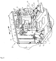
- the station box 1 denotes the station box of an IS machine, on which or on which a mold holding mechanism 2 is arranged.
- the station box 1 can be under overpressure, from which the cooling air supply is derived both for the molds and their mouth area, the cooling air guidance within the mold holding mechanism 2 being explained in more detail below.
- the mold holding mechanism 2 is designed, for example, to hold two molds 3, 4 intended for shaping hollow glass articles, each of which consists of two mold halves 5, 6 and 7, 8, respectively.
- the mold halves 5, 6, 7, 8 are carried by mold holders 9, 10, which are parallel within a housing section 11 with the participation of a drive, not shown in the drawing, in a horizontal plane in the direction of the arrows 12 between a closed position of the mold halves shown in the drawings and their open position are slidably arranged.
- 14 is the muzzle cooling, namely the connection of the cooling air supply intended for the muzzle area to the station housing 1 and 13 the mold cooling, namely the connection of the cooling air supply intended for the molds to the station housing 1, these connections being such that the Opening and closing movements of the mold halves 5, 6, 7, 8 are dependent on changes in distance and direction relative to the mold halves. This will be discussed in more detail below.
- the mold cooling 13 and the mouth cooling 14 are designed as 360 ° cooling systems. H. as cooling, which is effective uniformly during an entire cycle of an opening and closing movement of the mold halves 5 to 8.
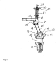
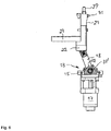
- the mold cooling 13 is characterized by a plate-like receptacle 15 which is arranged on the top 16 of the station housing 1 and which forms the link between a valve 17 arranged within the station housing 1 and a pivotably arranged cooling duct 18 with a rectangular cross section in the context of the cooling air duct.
- the cooling channel 18 ends on its side facing the receptacle 15 in a spherical guide body 19, which is received in a guide section 20 of the receptacle 15 corresponding to the profile, in this case representing a flow path for the cooling air, which leads from an air inlet 20 ′ through the guide section 19 leads into the cooling channel 18, wherein closing elements of the valve are arranged within this flow path.
- bearing cheeks are designated, which are integrally formed on the receptacle 15, in which the guide body 19 is rotatably supported on both sides about the axis 33 'by means of roller bearings. These roller bearings are completely enclosed within the bearing cheeks 32 and are lubricated for life.
- the end of the cooling channel 18 facing away from the receptacle 15 ends in a spherical bearing body 21 made of bronze, which lies sealingly on the inside of the inlet section 22, in this case representing a flow path into a cooling element 23, which ends in an arrangement of outlet slits 24 in the form of a ring section.
- the cooling channel 18 and the inlet section 22 are rectangular in cross section, so that during an opening or closing movement of the mold halves, the bearing body 21 executes a swiveling and sliding movement on the inside of the inlet section 22 to compensate for changes in length and angle.
- the fact that the bearing body 21 is arranged within a throttle housing 27 provides optimal protection of the sliding guide against the abrasive dirt occurring in the operating environment.
- valve 17, together with the housing including the cooling channel 18 mounted thereon, can remain in or on the station box 1, while the cooling element 23 remains on the mold holder of the closing mechanism.
- Said arrangement of the outlet slots 24 extends along a semicircle which is geometrically adapted to an arrangement of cooling air bores 25 which pass through the walls of each mold half 5 in an axis-parallel manner.
- the connection section 22 and the cooling piece 23 form part of an assembly 26, each of which carries a mold half 6 and is thus arranged to be movable in relation to the station box 1 in accordance with the opening and closing movements of the mold halves 5.
- Each mold half 6 is provided in its lower region with a step 46, which forms a horizontal annular segment surface, which is gripped by the cooling element 23, specifically in the region of the outlet slots 24 from which the cooling air emerges vertically and directly into the cooling air bores 25 Mold half 6 enters.
- Such cooling air holes 25 are provided along the entire circumference of the mold.
- the cooling piece 23 is secured on the step 46 by screws, so that it is easy to replace if necessary.
- the cooling piece 23 is preferably at a constant height in relation to the mold holder 9, so that no adaptation work is required when changing to a different mold height.
- the cooling piece 23 is preferably located in the lower half of the mold height, so that, depending on the respective blowing process, excessive cooling of the parison in the neck area, which at least impedes its elongation, is avoided.
- a stage of the assembly 26 is designated, which is located on the side facing the molds and on which the cooling element 23 is supported and secured with screws.
- a throttle housing is designated, which is also in connection with the assembly 26 and serves to accommodate a mechanism which is intended to change the flow cross section of the cooling air within the flow path between the connection section 22 and the cooling piece 23, here between a maximum and control a minimal opening.
- a blocking body 28 is provided, which can be displaced more or less into the flow cross-section mentioned by means of a spindle gear.
- Each of the spindle gears consists of a threaded spindle 29, which is operatively connected to an axially non-displaceably arranged spindle nut 30, the position of which can be fixed by means of a ball thrust piece 31 in defined locking positions, each corresponding to a specific flow cross section.
- each throttle housing 27 thus contains the means required for throttling the cooling air flow to form a mold half 5 to 8.
- Other divisions of the cooling air flow are also possible, for. B. an embodiment in which each throttle housing is assigned to half of a mold half 5 to 8.
- two threaded spindles 29 and thus two locking bodies 28 are assigned to each mold half 6.
- This grouping and likewise the constructive design of the drive of the locking bodies 28 can be varied as desired within the scope of the expert knowledge, but this will not be discussed in more detail. It is essential that, starting from an air inlet 20 via the valve 17, the line section 18, the connection section 22, the air distribution section 23, the outlet slots 24 and the cooling air bores 25, a continuous flow path for cooling the molds 3, 4 is shown, with the respective one Valve 17 a complete closure of the flow path can be represented and throttling of the cooling air flow can be achieved by actuating the blocking body 28.
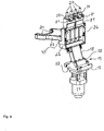
- the cooling structure 50 intended for the connection of the muzzle cooling is characterized by a base plate 33 on which a guide housing 34 which is suspended within the station box 1 is arranged.
- a structural unit which comprises a valve 37 and the cooling structure 50.
- the valve 37 and the cooling structure 50 are mounted on one another, so that flow-optimized lines for guiding cooling air are made available via the cooling structure 50, which end in outlet slots 35 on the side facing away from the base plate 33.
- the latter have a horizontal exit direction and are directed towards the mouth area of the respective shape.
- a cooling air flow to the mouth region of the mold can be completely blocked or opened via the valve 37.
- a throttle device 39 through the setting of which the cooling air flow reaching the mouth area can be reduced or increased.
- a cooling structure 38 having two outlet slots 35 is assigned to a mold half 5 as an example.
- the section 45 of the cooling structure 38 guiding the outlet slots 35 is held on the cooling structure 50 by a screw 44, so that an easy-to-assemble option is provided for replacing this section 45 when the shape changes due to the geometry or in the event of damage.
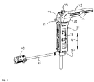
- the screw jack 40 with a screw jack is designated, which is connected via a drive shaft 41 to a drive 42, a stepper or servo motor, which protrudes from a rear wall 43 of the station box 1.
- the screw jack 40 is connected to the guide housing 34 and is used via a spindle shaft (not shown in the drawing) to adjust the height position of the outlet slots 35, so that the mouth region cooling according to the invention can be easily adapted to different mold heights. A height adjustment is thus possible by means of a motor-driven displacement of the cooling structure 38 in the direction of the arrows 36.
- a conversion to a different mold height can thus be carried out using an article database in which the height dimensions of different articles are stored. In this way, a simple and in particular quick conversion of the muzzle cooling to other mold heights can be carried out.
- the cooling piece 23 has a constant height in comparison to the mold holder 9, 10, so that in this respect no adaptation work is required when changing to a different mold height.
- the drive 42 protrudes from an opening in the end face 43 of the station box 1 and is arranged so that it is easily accessible. If necessary, it can be pulled out of the screw jack 40 together with the drive shaft 41 and used in the opposite direction.
- a centering aid can be provided in the station box 1 for simplified reinsertion into the screw jack 40.
- the screw jack 40 hangs on the underside of the guide housing 34 and is therefore located within the station box 1. It is therefore arranged to be protected against influences from the glass shaping process.
- the station box 1 can be under excess pressure to represent a cooling air supply. It can be seen that the valve 37 and in particular the screw jack 40 are arranged inside the station box 1 in a manner protected from abrasive environmental influences, in this case the glass manufacturing process.
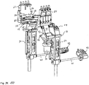
- Fig. 10 shows the juxtaposition of the above-described components of the mold and the mouth cooling 13, 14 according to the invention.
- the mold-holding mechanism according to the invention provides a flexible, service-friendly system for guiding cooling air, which is characterized by independent controls of a muzzle cooling and a mold cooling.
Landscapes
- Engineering & Computer Science (AREA)
- Chemical & Material Sciences (AREA)
- Manufacturing & Machinery (AREA)
- Materials Engineering (AREA)
- Organic Chemistry (AREA)
- Moulds For Moulding Plastics Or The Like (AREA)
- Re-Forming, After-Treatment, Cutting And Transporting Of Glass Products (AREA)
Description
- Die Erfindung bezieht sich auf eine Form- und Mündungskühlungsanordnung entsprechend den Merkmalen des Oberbegriffs des Anspruchs 1.
- Die Darstellung angemessener gleichförmiger und insbesondere reproduzierbarer Temperaturverhältnisse während des Formgebungsprozesses in den Vor- und Fertigformen einer Glasformmaschine, beispielsweise einer I.S. Maschine ist von großer Bedeutung für die eigentliche Formung, jedoch auch für die mechanischen Eigenschaften des Külbels bzw. des abschließend geformten Hohlglasartikels. Es geht hierbei um die eigentliche Formkühlung, welche durch Kühlmittelbohrungen in den Formwandungen bewirkt wird und um die Mündungskühlung, welche den Mündungsbereich des zu formenden Artikels, nämlich eines Hohlglasartikels betrifft. Hinzutritt die konstruktive Ausbildung aller zur Führung eines Kühlmittels, z. B. Kühlluft bestimmten Elemente, welche ein einfaches und rationelles Eingreifen für Wartungs- und Instandsetzungsarbeiten ermöglichen und gleichermaßen in ihrer konkreten Ausbildung für den Einsatz in der häufig abrasiven betrieblichen Atmosphäre einer Glashütte geeignet sein sollten.
- Nachdem die Formen üblicherweise aus Formhälften zusammengesetzt sind, die während des Formgebungsprozesses zwischen einer Öffnungs- und einer Schließstellung bewegbar angeordnet sind, muss bei dem Konzept der Kühlmittelführung ein beweglicher Abschnitt vorgesehen werden, der das Bindeglied zwischen einer fest, beispielsweise in einem Stationskasten angeordneten Kühlmittelversorgung und den demgegenüber entsprechend der Öffungs- und Schließbewegung beweglichen Teilen bildet. Von Bedeutung ist ferner die Frage, wie komplex sich in arbeitstechnischer Hinsicht eine Umrüstung auf eine andere Formenhöhe gestaltet.
- Es hat sich gezeigt, dass den vorstehend aufgelisteten Anforderungen mit den bisher bekannten Ausführungsformen einer Kühlungsanordnung nur unvollkommen begegnet werden kann.
- Die bekannten Ausführungsformen sind dadurch gekennzeichnet, dass eine Form-und eine Mündungskühlung aus einer gemeinsamen Öffnung des Stationskastens mit Kühlluft versorgt werden. Ein Einsatz von getrennt schaltbaren, insbesondere für die Formkühlung ausreichend dimensionierten Ventilen ist damit häufig nicht möglich.
- Eine gattungsgemäße Form- und Mündungskühlungsanordnung ist aus
EP 1 149 806 A2 bekannt, bei der eine Mündungskühlung und eine Formkühlung unabhängige voneinander eingerichtet sind. Hierbei ist jedoch ein teleskopierbares Kühlrohr als Teil der Formkühlung vorgesehen, so dass die zum Längenausgleich bestimmten Funktionselemente gegenüber betrieblichen Umgebungseinfflüßen ungeschützt angeordnet sind. - Es ist daher die Aufgabe der Erfindung, eine Form- und Mündungskühlungsanordnung der eingangs bezeichneten Art mit Hinblick auf die Kühlluftführung, die Verschleißanfälligkeit, die Komplexität von Umrüstarbeiten sowie die Wartungsfreundlichkeit hin zu verbessern. Gelöst ist diese Aufgabe bei einer solchen Form-und Mündungskühlungsanordnung durch die Merkmale des Kennzeichnungsteils des Anspruchs 1.
- Erfindungswesentlich ist hiernach eine von der Mündungskühlung unabhängige Formkühlung, in die ein Kühlkanal eingebunden ist, der das Bindeglied zwischen ortsfest angeordneten Teilen wie einem Stationskasten und beweglichen Teilen wie einem Formenhalter bildet. Der Kühlkanal steht an seinem einen Ende gelenkig, z. B. um eine Achse schwenkbar mit dem Stationskasten und an seinem anderen Ende gelenkig, beispielsweise schwenkbar sowie einen Längenausgleich ermöglichend mit einer Baugruppe in Verbindung, die an dem Formenhalter angeordnet ist. Dies eröffnet die Möglichkeit, die zur Darstellung der Schwenkbarkeit sowie des Längenausgleichs des Kühlkanals benötigten baulichen Funktionselemente gegenüber Verschmutzung und sonstigen betrieblichen Umgebungseinflüssen geschützt anzuordnen, nämlich an bzw. in dem Stationsgehäuse sowie in die genannte Baugruppe einbezogen. Dies eröffnet ferner die Möglichkeit, einen Kühlkanal mit einem großen Querschnitt einzusetzen, der im Rahmen der Öffnungs- und Schließbewegungen der Formenhalter lediglich geringe Ausgleichsbewegungen ausführt, so dass ein dementsprechend nur geringer Verschleiß entsteht. Erreicht wird ein äußerst flexibler, an der Darstellung einer artikelspezifisch angemessenen Kühlleistung orientierter Betrieb des Glasformungsprozesses.
- Die Mündungskühlung ist von der Formkühlung getrennt, nachdem diesen voneinander getrennte Öffnungen des Stationsgehäuses zugeordnet sind. Auf diese Weise wird ein Einsatz von getrennt schaltbaren Ventilen im Rahmen der Formkühlung sowie der Mündungskühlung und insbesondere für die Formkühlung, jedoch auch für die Mündungskühlung die Verwendung von ausreichend dimensionierten Ventilen möglich. Aus dem Stand der Technik bekannt ist demgegenüber die gemeinsame Versorgung von Mündungs- und Formkühlung aus einer Öffnung je Seite im Stationskasten.
- Das Kühlstück bildet das Bindeglied zwischen der genannten Baugruppe und einer Formhälfte bildet. Das Kühlstück ist auf seinem der Formhälfte zugekehrten Ende mit vertikal orientierten Luftaustritten versehen, die in einem zum Untergreifen einer Stufe der Formhälfte bestimmten Abschnitt angeordnet sind und auf diese Weise in eine durchgängige Verbindung mit den Kühlluftbohrungen der Formhälfte bringbar sind. Das Kühlstück steht aus Gründen des einfachen Austauschs lösbar mit der Baugruppe in Verbindung.
- Durch die gleitfähige Aufnahme des Kühlkanals innerhalb des Aufnahmeabschnitts ist eine Längsverschieblichkeit dargestellt, so dass außerhalb des Aufnahmeabschnitts keine Maßnahmen wie beispielsweise eine teleskopierbare Ausgestaltung des Kühlkanals anfallen, die den betrieblichen Umgebungseinflüssen des Glasformprozesses ausgesetzt sind. Wesentlich ist, dass bei dieser Art der Ausgestaltung Verschleißgesichtspunkte beachtet worden sind, so dass Gleitflächen sowie sonstige Lagerstellen geschützt angeordnet sind. Soweit Schmierstellen vorgesehen sind, sollten diese entsprechend der geplanten Lebensdauer eingerichtet sein.
- Der entsprechend den Merkmalen des Anspruchs 2 vorgesehene Anschlussabschnitt steht mit der genannten Baugruppe in Verbindung und ist intern mit zur Darstellung einer schwenkbaren sowie längsverschiebbaren Aufnahme des Kühlkanals ausgerüstet. Der Anschlussabschnitt dient somit der Darstellung einer geschützten Aufnahme des diesem zugekehrten Endes des Kühlkanals.
- Gemäß den Merkmalen der Ansprüche 3 und 4 steht die den Anschlussabschnitt tragende Baugruppe lösbar mit einem Formenhalter in Verbindung und beinhaltet ein Drosselgehäuse. Sie ist somit im Bedarfsfall einfach austauschbar. In dem Drosselgehäuse ist ein Sperrkörper beweglich aufgenommen, durch dessen Gestalt und Position innerhalb des Strömungspfades der Kühlluft im Rahmen der Formkühlung der Kühlluftstrom verändert werden kann. Die Kühlluftströme einer rechten und einer linken Hälfte einer Formhälfte können unabhängig voneinander eingestellt werden.
- Der Kühlkanal weist entsprechend den Merkmalen des Anspruchs 5 einen rechteckigen Querschnitt auf.
- Gemäß den Merkmalen der Ansprüche 6 und 7 befindet sich die zur Auflagerung der Formhälfte bestimmte Stufe in deren unterem Bereich. Die Kühlluft durchströmt die Wandungen innerhalb der Kühlluftbohrungen somit von unten nach oben. Auf diese Weise wird verhindert, dass sich in einer Vorform eine übermäßige Abkühlung des Halsbereichs des geformten Hohlglasartikels ergibt, wobei gleichzeitig eine ausreichende Kühlung des Bodenbereichs darstellbar ist. Zusätzlich wird auf diesem Wege vermieden, dass sich die Oberfläche des Stationskastens aufheizt und es zu Verwirbelungen bzw. Beeinträchtigungen der Mündungskühlluft kommt. Eine umgekehrte Strömungsrichtung der Kühlluft und eine dementsprechende Anordnung des Kühlstücks relativ zu der Formhälfte wird jedoch nicht ausgeschlossen.
- Die Merkmale der Ansprüche 8 und 9 sind auf eine weitere konstruktive Konkretisierung der Anordnung des Kühlstücks gerichtet. Die genannte Baugruppe ist mit einer Stufe versehen, auf der das Kühlstück aufgelagert ist. Dadurch, dass sich das Kühlstück auf einer im Verhältnis zu dem Formhalter festen Höhenlage befindet, entfällt bei einem Übergang auf eine andere Formenhöhe eine Höhenanpassung, so dass sich insoweit Umrüstarbeiten vereinfachen. Die Formenkühlung ist als 360° Kühlung eingerichtet.
- Die Merkmale der Ansprüche 10 bis 14 sind auf eine Ausgestaltung der Mündungskühlung gerichtet. Diese umfasst einen teilweise innerhalb des Stationsgehäuses angeordneten, höhenverstellbaren Kühlungsaufbau, der an seinem, aus dem Stationskasten herausragenden Ende mit einem Austrittsschlitze aufweisenden Abschnitt versehen ist. Dieser Abschnitt steht zwecks Anpassung an unterschiedliche Formhälften vorzugsweise lösbar mit dem Kühlungsaufbau in Verbindung und es weisen die Austrittsschlitze eine horizontale, auf den Mündungsbereich des geformten Hohlglasartikels hin gerichtete Ausströmungsrichtung auf. Der Kühlungsaufbau ist innerhalb eines Führungsgehäuses verschiebbar, insbesondere höhenverstellbar angeordnet, welches seinerseits fest mit dem Stationskasten in Verbindung steht. Der Höhenver-stellbarkeit ist ein Antrieb zugeordnet, der über eine Antriebswelle mit einem Spindel-hubgetriebe in Verbindung steht. Unter dem Führungsgehäuse, somit innerhalb des Stationskastens hängt das Spindelhubgetriebe, welches somit optimal gegenüber Umgebungseinflüßen aus dem Glasfertigungsprozess geschützt angeordnet ist.
- Der zur Höheneinstellung der Mündungskühlung, insbesondere des Kühlungsaufbaus bestimmte Antrieb ist entsprechend den Merkmalen des Anspruchs 15 außenseitig an dem Stationskasten angebracht und somit für Reparatur- und Inspektionszwecke gut zugänglich. Im Rahmen des Antriebs kann beispielsweise ein Servomotor oder ein Schrittmotor eingesetzt werden, so dass eine sehr genaue Höheneinstellung möglich ist. Der Antrieb kann bei einem Austausch der Mündungskühlung einschließlich seiner Antriebswelle aus dem Spindelhubgetriebe herausgezogen werden.
- In Verbindung mit einer Artikeldatenbank, in der unterschiedliche Höhenmaße der eingesetzten Formen gespeichert sind, ist entsprechend den Merkmalen des Anspruchs 16 eine automatische Höheneinstellung der Mündungskühlung darstellbar.
- Die für die Mündungskühlung eingerichteten Strömungspfade sind entsprechend den Merkmalen des Anspruchs 17 mit Einrichtungen zur Drosselung des Kühlluftstromes ausgerüstet, so dass insoweit eine Anpassung der Kühlleistung an den erforderlichen Bedarf gegeben ist. Der vorzugsweise aus Guss bestehende Kühlungsaufbau ist strömungsoptimiert gestaltet und kann mit Einrichtungen zur Drosselung jeweils für eine Hälfte eines Mündungsformwerkzeugs versehen sein.
- Die erfindungsgemäße Kühlluftführung ist hauptsächlich für die Kühlung der Vorform in Verbindung mit einem Parallelschließmechanismus bestimmt.
- Die Erfindung wird im Folgenden unter Bezugnahme auf das in den Zeichnungen dargestellte Ausführungsbeispiel näher erläutert werden. Es zeigen:
- Fig. 1
- eine perspektivische seitliche Ansicht eines Formenschließmechanismus mit Form- und Mündungskühlung einer Glasformmaschine;
- Fig. 2
- eine perspektivische vorderseitige Ansicht des Formenschließmechaanismus mit Form- und Mündungskühlung gemäß
Fig. 1 ; - Fig. 3
- eine isolierte perspektivische seitliche Ansicht der Kühlluftführung für die Formen;
- Fig. 4
- eine isolierte perspektivische rückseitige Ansicht der Kühlluftführung für die Formen;
- Fig. 5
- eine Teilansicht der Kühlluftführung gemäß
Fig. 3 in einer Schnittdarstellung; - Fig. 6
- eine Teilansicht gemäß der Kühlluftführung gemäß
Fig. 5 in teilweiser Schnittdarstellung; - Fig. 7
- eine isolierte perspektivische seitliche Ansicht der Kühlluftführung für die Mündungskühlung;
- Fig. 8
- eine perspektivische Ansicht des den Formhaltermechanismus gemäß
Fig. 1 tragenden Stationskastens; - Fig. 9
- eine teilweise Schnittansicht der Kühlluftführung gemäß
Fig. 7 ; - Fig. 10
- eine perspektivische Gesamtansicht der Kühlluftführungen für die Form-sowie die Mündungskühlung.
- Mit 1 ist in den
Figuren 1 und2 der Stationskasten einer I.S. Maschine bezeichnet, auf dem bzw. an dem ein Formenhaltemechanismus 2 angeordnet ist. Zur Darstellung einer Kühlluftversorgung kann der Stationskasten 1 unter Überdruck stehen, von dem die Kühlluftversorgung sowohl für die Formen als auch deren Mündungsbereich abgeleitet wird, wobei im Folgenden die Kühlluftführung innerhalb des Formenhaltemechanismus 2 näher erläutert wird.
Der Formenhaltemechanismus 2 ist beispielhaft zur Halterung von zwei zur Formgebung von Hohlglasartikeln bestimmten Formen 3, 4 eingerichtet, die jeweils aus zwei Formhälften 5, 6 bzw. 7, 8 bestehen. Die Formhälften 5, 6, 7, 8 werden von Formhaltern 9, 10 getragen, die innerhalb eines Gehäuseabschnitts 11 unter Mitwirkung eines zeichnerisch nicht dargestellten Antriebs in einer Horizontalebene in Richtung der Pfeile 12 zwischen einer in den Zeichnungen dargestellten Schließstellung der Formhälften und deren Öffnungsstellung parallel verschiebbar angeordnet sind.
Mit 14 ist die Mündungskühlung, nämlich die Anbindung der für den Mündungsbereich bestimmten Kühlluftzufuhr an das Stationsgehäuse 1 und mit 13 die Formkühlung, nämlich die Anbindung der für die Formen bestimmten Kühlluftzufuhr an das Stationsgehäuse 1 bezeichnet, wobei diese Anbindungen derart beschaffen sind, dass durch die Öffnungs- und Schließbewegung der Formhälften 5, 6, 7, 8 bedingte Abstands- und Richtungsänderungen relativ zu den Formhälften überbrückbar sind. Hierauf wird im Folgenden noch näher eingegangen werden. - Wie im Folgenden ebenfalls noch erläutert werden wird, sind die Formkühlung 13 sowie die Mündungskühlung 14 als 360° Kühlungen angelegt, d. h. als Kühlung, die gleichförmig während eines gesamten Zyklus einer Öffnungs- und Schließbewegung der Formhälften 5 bis 8 wirksam ist.
- In den
Figuren 3 bis sind Funktionselemente, die mit denjenigen derFiguren 1 und2 übereinstimmen, entsprechend beziffert, so dass auf eine diesbezügliche wiederholte Beschreibung verzichtet werden kann. - Die Formkühlung 13 ist durch eine plattenartige Aufnahme 15 gekennzeichnet, die auf der Oberseite 16 des Stationsgehäuses 1 angeordnet ist und welche im Rahmen der Kühlluftführung das Bindeglied zwischen einem innerhalb des Stationsgehäuses 1 angeordneten Ventil 17 und einem schwenkbar angeordneten, im Querschnitt rechteckigen Kühlkanal 18 bildet. Der Kühlkanal 18 endet auf seiner, der Aufnahme 15 zugekehrten Seite in einem balligen Führungskörper 19, welcher in einem dem profilmäßig entsprechenden Führungsabschnitt 20 der Aufnahme 15 aufgenommen ist, hierbei einen Strömungspfad für die Kühlluft darstellend, der von einem Lufteinlaß 20' durch den Führungsabschnitt 19 in den Kühlkanal 18 führt, wobei Schließorgane des Ventils innerhalb dieses Strömungspfades angeordnet sind.
Mit 32 sind Lagerwangen bezeichnet, die seitlich an der Aufnahme 15 angeformt sind, in denen mittels Wälzlagern der Führungskörper 19 beidseitig um die Achse 33' drehbar gelagert ist. Diese Wälzlager sind innerhalb der Lagerwangen 32 vollständig eingehaust und auf Lebensdauer geschmiert. - Das der Aufnahme 15 abgekehrte Ende des Kühlkanals 18 endet in einem aus Bronze bestehenden, balligen Lagerkörper 21, der an der Innenseite des Einlaufabschnitts 22 dichtend anliegt, hierbei einen Strömungspfad in ein Kühlstück 23 hinein darstellend, der in einer Anordnung kreisringabschnittartiger Austrittsschlitze 24 endet. Der Kühlkanal 18 und der Einlaufabschnitt 22 sind im Querschnitt rechteckig ausgebildet, so dass während einer Öffnungs- oder Schließbewegung der Formhälften der Lagerkörper 21 auf der Innenseite des Einlaufabschnitts 22 eine Schwenk- und Gleitbewegung zum Ausgleich von Längen- und Winkeländerungen ausführt. Dadurch, dass der Lagerkörper 21 innerhalb eines Drosselgehäuses 27 angeordnet ist, ist ein optimaler Schutz der Gleitführung gegenüber dem in der betrieblichen Umgebung anfallenden abrasiv wirkenden Schmutz gegeben.
- Man erkennt, dass die technische Umsetzung dieser Bewegungsverhältnisse durch lediglich geringe Relativbewegungen der aufeinander gleitenden Elemente gekenn-zeichnet sind, so dass ein dementsprechend geringer Verschleiß zu erwarten ist.
- Man erkennt ferner, dass aufgrund der beidseitig gelenkigen Anbindung des Kühlkanals 18 die Öffnungs- und Schließbewegungen der Formhälften behinderungsfrei ausführbar sind.
- Bei einem Ausbau des Schließmechanismus können das Ventil 17 nebst Gehäuse einschließlich des darauf gelagerten Kühlkanals 18 in bzw. auf dem Stationskasten 1 verbleiben, während das Kühlstücks 23 am Formenhalter des Schließmechanismus verbleibt.
- Die genannte Anordnung der Austrittsschlitze 24 erstreckt sich entlang eines Halbkreises, der geometrisch an eine Anordnung von Kühlluftbohrungen 25 angepasst ist, welche die Wandungen einer jeden Formhälfte 5 achsparallel durchziehen. Der Anschlussabschnitt 22 und das Kühlstück 23 bilden einen Teil einer Baugruppe 26, welche jeweils eine Formhälfte 6 trägt und somit nach Maßgabe der Öffungs- und Schließbewegungen der Formhälften 5 gegenüber dem Stationskasten 1 beweglich angeordnet ist.
- Jede Formhälfte 6 ist in ihrem unteren Bereich mit einer Stufe 46 versehen, welche eine horizontale Kreisringsegmentfläche bildet, welche von dem Kühlstück 23, und zwar in dem Bereich der Austrittssschlitze 24 untergriffen ist, aus denen die Kühlluft vertikal austritt und direkt in die Kühlluftbohrungen 25 der Formhälfte 6 eintritt. Derartige Kühlluftbohrungen 25 sind entlang des gesamten Umfangs der Form vorhanden. Das Kühlstück 23 ist auf der Stufe 46 durch Schrauben gesichert, so dass im Bedarfsfall eine einfache Austauschbarkeit gegeben ist. Das Kühlstück 23 befindet sich vorzugsweise auf einer im Verhältnis zu dem Formenhalter 9 konstanten Höhe, so dass beim Übergang auf eine andere Formenhöhe keinerlei Anpassungsarbeiten erforderlich sind.
- Das Kühlstück 23 befindet sich vorzugsweise in der unteren Häfte der Formenhöhe, so dass nach Maßgabe des jeweiligen Blasverfahrens eine zu starke Abkühlung des Külbels im Halsbereich, welche dessen Längung zumindest behindert, vermieden wird. Durch die in den Kühlluftbohrungen 25 aufwärts strömende Kühlluft wird neben einer hinreichenden Kühlung des Bodenbereichs des Külbels in der Vorform verhindert, dass sich die Oberfläche des Stationskastens 1 übermäßig aufheizt, welches mit dem Risiko von Verwirbelungen und Beeinträchtigungen der Mündungskühlung einhergeht.
- Mit 47 ist eine Stufe der Baugruppe 26 bezeichnet, die sich auf deren, den Formen zugekehrten Seite befindet und auf der das Kühlstück 23 aufgelagert sowie mit Schrauben gesichert ist.
- Mit 27 ist ein Drosselgehäuse bezeichnet, welches ebenfalls mit der Baugruppe 26 in Verbindung steht und der Aufnahme eines Mechanismus dient, der dazu bestimmt ist, den Strömungsquerschnitt der Kühlluft innerhalb des Strömungspfades zwischen dem Anschlußabschnitt 22 und dem Kühlstück 23 zu verändern, hier zwischen einer maximalen und einer minimalen Öffnung zu steuern. Zu diesem Zweck ist ein Sperrkörper 28 vorgesehen, der mittels eines Spindelgetriebes mehr oder weniger in den genannten Strömungsquerschnitt verschiebbar ist. Ein jedes der Spindelgetriebe besteht aus einer Gewindespindel 29, welche mit einer axial unverschiebbar angeordneten Spindelmutter 30 in Wirkverbindung steht, deren Position in definierten, jeweils einem bestimmten Strömungsquerschnitt entsprechenden Rastpositionen mittels eines Kugeldruckstücks 31 fixierbar ist.
- Die Baugruppe 26 und mit dieser das Drosselgehäuse 27 sind mittels Schrauben 48, 49 an dem jeweiligen Formenhalter 9 befestigt. In jedem Drosselgehäuse 27 befinden sich somit jeweils die für die Drosselung des Kühlluftstromes zu einer Formhälfte 5 bis 8 erforderlichen Mittel. Andere Teilungen des Kühlluftstromes sind ebenfalls möglich, so z. B. eine Ausführung, bei der jedes Drosselgehäuse jeweils der Hälfte einer Formhälfte 5 bis 8 zugeordnet ist.
- In dem gezeigten Ausführungsbeispiel sind jeweils einer Formhälfte 6 zwei Gewindespindeln 29 und damit zwei Sperrkörper 28 zugeordnet. Diese Gruppierung und gleichermaßen die konstruktive Ausbildung des Antriebs der Sperrkörper 28 können im Rahmen des fachmännischen Kenntnisstandes beliebig variiert werden, worauf jedoch nicht näher eingegangen werden wird. Wesentlich ist, dass ausgehend von einem Lufteinlaß 20 über das Ventil 17, den Leitungsabschnitt 18, den Anschlussabschnitt 22, den Luftverteilungsabschnitt 23, die Austrittsschlitze 24 und die Kühlluftbohrungen 25 ein durchgängiger Strömungsspfad zur Kühlung der Formen 3, 4 dargestellt ist, wobei über das jeweilige Ventil 17 eine völlige Schließung des Strömungspfades darstellbar ist und wobei durch Ansteuerung der Sperrkörper 28 eine Drosselung des Kühlluftstromes erreichbar ist.
- Der für die Anbindung der Mündungskühlung bestimmte Kühlungsaufbau 50 ist durch eine Grundplatte 33 gekennzeichnet, an der ein innerhalb des Stationskastens 1 hängendes Führungsgehäuse 34 angeordnet ist. Innerhalb des Führungsgehäuses 34, in den Richtungen der Pfeile 36 vertikal verschiebbar ist eine Baueinheit, welche ein Ventil 37 sowie den Kühlungsaufbau 50 umfasst. Das Ventil 37 und der Kühlungsaufbau 50 sind aufeinander montiert, so dass über den Kühlungsaufbau 50 strömungsoptimierte Leitungen zur Führung von Kühlluft zur Verfügung gestellt werden, die auf der, der Grundplatte 33 abgekehrten Seite in Austrittsschlitzen 35 enden. Letztere weisen eine horizontale Austrittsrichtung auf und sind auf den Mündungsbereich der jeweiligen Form gerichtet.
- Über das Ventil 37 kann ein Kühlluftstrom zu dem Mündungsbereich der Form zur Gänze gesperrt bzw. geöffnet werden.
- Innerhalb der Leitungen des aus Guss bestehenden Kühlungsaufbaus 14, 38 befindet sich jeweils eine Drosseleinrichtung 39, über deren Einstellung sich der auf den Mündungsbereich gelangende Kühlluftstrom vermindern oder erhöhen läßt. In dem gezeigten Ausführungsbeispiel ist beispielhaft ein zwei Austrittsschlitze 35 aufweisender Kühlungsaufbau 38 einer Formhälfte 5 zugeordnet. Der die Austrittsschlitze 35 führende Abschnitt 45 des Kühlungsaufbau 38 ist durch eine Schraube 44 an dem Kühlungsaufbau 50 gehalten, so dass eine montagemäßig einfach handhabbare Möglichkeit eingeräumt ist, diesen Abschnitt 45 bei einem Wechsel der Form aus Gründen der Geometrie oder im Fall einer Beschädigung auszutauschen.
- Mit 40 ist ein Spindelhubgetriebe bezeichnet, welches über eine Antriebswelle 41 mit einem Antrieb 42, einem Schritt- oder Servomotor in Verbindung steht, der aus einer rückseitigen Wandung 43 des Stationskastens 1 herausragt. Das Spindelhubgetriebe 40 steht mit dem Führungsgehäuse 34 in Verbindung und dient über eine zeichnerisch nicht dargestellte Spindelwelle der Verstellung der Höhenposition der Austrittsschlitze 35, so dass die erfindungsgemäße Mündungsbereichskühlung in einfacher Weise an unterschiedliche Formenhöhen anpassbar ist. Eine Höhenverstellung ist somit durch eine motorisch durchführbare Verschiebung des Kühlungsaufbaus 38 in Richtung der Pfeile 36 möglich.
- Ein Umbau auf eine andere Formenhöhe kann somit unter Benutzung einer Artikeldatenbank abgewickelt werden, in der die Höhenmaße unterschiedlicher Artikel gespeichert sind. Auf diese Weise ist eine einfache und insbesondere schnelle Umrüstung der Mündungskühlung auf andere Formenhöhen durchführbar.
- Erfindungsgemäß weist das Kühlstück 23 eine konstante Höhe im Vergleich zu dem Formenhalter 9, 10 auf, so dass insoweit bei einem Übergang auf eine andere Formenhöhe keine Anpassungsarbeiten erforderlich sind.
Der Antrieb 42 ragt aus einer Öffnung in der Stirnseite 43 des Stationskastens 1 heraus und ist auf diese Weise gut zugänglich angeordnet. Er kann im Bedarfsfall zusammen mit der Antriebswelle 41 aus dem Spindelhubgetriebe 40 herausgezogen und in umgekehrter Richtung eingesetzt werden. Für ein vereinfachtes erneutes Einsetzen in das Spindelhubgetriebe 40 kann im Stationskasten 1 eine zeichnerisch nicht dargestellte Zentrierhilfe zur Verfügung gestellt werden. - Das Spindelhubgetriebe 40 hängt unterseitig an dem Führungsgehäuse 34 und befindet sich somit innerhalb des Stationskastens 1. Es ist somit gegenüber Beeinflussungen aus dem Glasformgebungsprozess geschützt angeordnet.
- Zur Darstellung einer Kühlluftversorgung kann der Stationskasten 1 unter Überdruck stehen. Man erkennt, dass das Ventil 37 und insbesondere das Spindelhubgetriebe 40 innerhalb des Stationskastens 1 vor abrasiven Umgebungseinflüssen, hier des Glasfertigungsprozesses geschützt angeordnet sind.
-
Fig. 10 zeigt das erfindungsgemäße Nebeneinander der vorstehend beschriebenen Komponenten der Form- und der Mündungskühlung 13, 14. - Man erkennt, dass mit dem erfindungsgemäßen Formenhaltemechanismus ein flexibles, servicefreundlich ausgebildetes System zur Kühlluftführung zur Verfügung gestellt wird, welches durch voneinander unabhängige Steuerungen einer Mündungskühlung und einer Formkühlung gekennzeichnet ist.
-
- 1.
- Stationskasten
- 2.
- Formenhaltemechanismus
- 3.
- Form
- 4.
- Form
- 5.
- Formhälfte
- 6.
- Formhälfte
- 7.
- Formhälfte
- 8.
- Formhälfte
- 9.
- Formhalter
- 10.
- Formhalter
- 11.
- Gehäuseabschnitt
- 12.
- Pfeile
- 13.
- Formkühlung
- 14.
- Mündungskühlung
- 15.
- Aufnahme
- 16.
- Oberseite
- 17.
- Ventil
- 18.
- Kühlkanal
- 19.
- Führungskörper
- 20.
- Führungsabschnitt
- 20.
- Lufteinlaß
- 21.
- Bronzestück
- 22.
- Anschlußabschnitt
- 23.
- Kühlstück
- 24.
- Luftaustritt
- 25.
- Kühlluftbohrung
- 26.
- Baugruppe
- 27.
- Drosselgehäuse
- 28.
- Sperrkörper
- 29.
- Gewindespindel
- 30.
- Spindelmutter
- 31.
- Kugeldruckstück
- 32.
- Lagerwange
- 33.
- Grundplatte
- 33.
- Achse
- 34.
- Führungsgehäuse
- 35.
- Austrittsschlitz
- 36.
- Pfeile
- 37.
- Ventil
- 38.
- Kühlungsaufbau
- 39.
- Drosseleinrichtung
- 40.
- Spindelhubgetriebe
- 41.
- Antriebswelle
- 42.
- Antrieb
- 43.
- Stirnseite
- 44.
- Schraube
- 45.
- Abschnitt
- 46.
- Stufe
- 47.
- Stufe
- 48.
- Schraube
- 49.
- Schraube
- 50.
- Kühlungsaufbau
Claims (17)
- Form- und Mündungskühlungsanordnung für eine Glasformmaschine mit einem Stationskasten (1), mit wenigstens einer, aus zwei Formhälften (5, 6, 7, 8) zusammengesetzten Form (3, 4), wobei die Formhälften jeweils an einem Formhalter (9, 10) angeordnet und mittels eines Antriebs zwischen einer Öffnungs- und einer Schließstellung bewegbar sind, wobei jeder Form (3, 4) eine Mündungskühlung (13) und eine Formkühlung (14) zugeordnet ist, wobei innerhalb des Stationskastens (1) eine Kühlluftversorgung eingerichtet ist, wobei die Mündungskühlung (13) sowie die Formkühlung (14) unabhängig voneinander sowie an voneinander getrennten Öffnungen des Stationskastens (1) angeschlossen sind, wobei die Formkühlung (14) einen Kühlkanal (18) auf-weist, dessen eines Ende gelenkig mit dem Stationskasten (1) in Verbindung steht, dadurch gekennzeichnet, dass das andere Ende der Formkühlung (14) gelenkig sowie einen Längenausgleich ermöglichend mit einer Baugruppe (26) in Verbindung steht, die ihrerseits durch einen Formenhalter (8, 9) gehalten ist, mit einem, ein Bindeglied zu wenigstens einer Formhälfte (5, 6, 7, 8) bildenden, lösbar mit der Baugruppe (26) in Verbindung stehenden Kühlstück (23), dass der Kühlkanal (18) an seinem, dem Stationskasten (1) zugekehrten Ende um eine horizontale Achse (33') schwenkbar und an seinem, dem Stationskasten (1) abgekehrten Ende in einem Anschlussabschnitt (22) der Baugruppe (26) gleitfähig aufgenommen ist.
- Form- und Mündungskühlungsanordnung nach Anspruch 1, dadurch gekenn-zeichnet, dass das genannte andere Ende des Kühlkanals (18) in einen Anschlussabschnitt (22) der Baugruppe (26) eingesteckt ist.
- Form- und Mündungskühlungsanordnung nach einem der Ansprüche 1 oder 2, dadurch gekennzeichnet, dass die Baugruppe (26) lösbar mit einem Formhalter (9, 10) in Verbindung steht und ein Drosselgehäuse (27) umfasst, welches mit Mitteln zur Veränderung des Kühlluftstromes der Formkühlung (14) ausgerüstet ist.
- Form- und Mündungskühlungsanordnung nach Anspruch 3, dadurch gekenn-zeichnet, dass die genannten Mittel durch einen Sperrkörper (28) dargestellt sind, der in einen Strömungspfad des Kühlluftstromes, dessen Querschnitt verändernd, schiebbar ist.
- Form- und Mündungskühlungsanordnung nach einem der Ansprüche 1 bis 4, dadurch gekennzeichnet, dass der Kühlkanal (18) einen rechteckigen Querschnitt aufweist und über ein Ventil (17) mit dem Stationskasten (1) in Wirkverbindung steht.
- Form- und Mündungskühlungsanordnung nach einem der Ansprüche 1 bis 5, dadurch gekennzeichnet, dass das Kühlstück (23) eine Anordnung von Luftaustritten (24) mit senkrecht orientierter Austrittsrichtung aufweist und dass der die Luftaustritte (24) tragende Teil des Kühlstücks (23) zum Untergreifen einer Stufe (46) einer Formhälfte (5, 6, 7, 8) eingerichtet ist, hierbei mit den Kühlluftbohrungen (25) der Formhälften (5, 6, 7, 8) jeweils durchgängige Strömungspfade bildend.
- Form- und Mündungskühlungsanordnung nach Anspruch 6, dadurch gekenn-zeichnet, dass sich die Stufe (46) im Bereich der unteren Hälfte der Höhe einer Formhälfte (5, 6, 7, 8) befindet.
- Form- und Mündungskühlungsanordnung nach einem der Ansprüche 1 bis 7, dadurch gekennzeichnet, dass das Kühlstück (23) auf einer Stufe (47) der Baugruppe (26) aufgelagert ist und lösbar mit dieser in Verbindung steht.
- Form- und Mündungskühlungsanordnung nach einem der Ansprüche 1 bis 8, dadurch gekennzeichnet, dass das Kühlstück (23) auf einer im Verhältnis zu dem Formhalter (9, 10) festen Höhenlage befindet.
- Form- und Mündungskühlungsanordnung nach einem der Ansprüche 1 bis 9, dadurch gekennzeichnet, dass die Mündungskühlung (13) einen teilweise innerhalb des Stationskastens (1) angeordneten, ein Ventil (37) tragenden Kühlungsaufbau (38) aufweist, der an seinem, dem Stationskasten (1) abgekehrten Ende Austrittsschlitze (35) aufweist.
- Form- und Mündungskühlungsanordnung nach Anspruch 10, dadurch gekenn-zeichnet, dass der Kühlungsaufbau (38) an seinem den Austrittsschlitzen (35) zugekehrten Ende einen lösbar angeordneten, die Austrittsschlitze (35) tra-genden Abschnitt (45) aufweist.
- Form- und Mündungskühlungsanordnung nach Anspruch 10 oder 11, dadurch gekennzeichnet, dass der Kühlungsaufbau (38) höhenverstellbar gegenüber dem Stationskasten (1) angeordnet ist.
- Form- und Mündungskühlungsanordnung nach einem der Ansprüche 10 bis 12, dadurch gekennzeichnet, dass die Austrittsschlitze (35) eine horizontale Ausströmungsrichtung aufweisen.
- Form- und Mündungskühlungsanordnung nach einem der Ansprüche 11 bis 13, dadurch gekennzeichnet, dass der Kühlungsaufbau (38) innerhalb eines Führungsgehäuses (34) höhenverstellbar angeordnet ist, dass das Führungsgehäuse (34) mit dem Stationskasten (1) in Verbindung steht und dass zur Darstellung der Höhenverstellbarkeit ein Spindelhubgetriebe (40) vorgesehen ist, welches über eine Antriebswelle (41) mit einem Antrieb (42) in Verbindung steht .
- Form- und Mündungskühlungsanordnung nach Anspruch 14, dadurch gekennzeichnet, dass der Antrieb (42) außenseitig an dem Stationskasten (1) angeordnet ist.
- Form- und Mündungskühlungsanordnung nach Anspruch 14 oder 15, gekennzeichnet durch eine Artikeldatenbank, in der unterschiedliche Höhenmaße der eingesetzten Formen (3, 4) gespeichert sind und die mit dem Antrieb (42) in Wirkverbindung steht.
- Form- und Mündungskühlungsanordnung nach einem der Ansprüche 1 bis 16, dadurch gekennzeichnet, dass innerhalb der für die Mündungskühlung (13) eingerichteten Strömungspfade für die Kühlluft Einrichtungen zur Drosselung des Kühlluftstromes angeordnet sind.
Priority Applications (1)
| Application Number | Priority Date | Filing Date | Title |
|---|---|---|---|
| PL17757685T PL3510001T3 (pl) | 2016-09-09 | 2017-08-07 | Układ chłodzenia formy i ujścia przeznaczony do maszyny do formowania wyrobów szklanych |
Applications Claiming Priority (2)
| Application Number | Priority Date | Filing Date | Title |
|---|---|---|---|
| DE102016010802.9A DE102016010802A1 (de) | 2016-09-09 | 2016-09-09 | Form- und Mündungskühlungsanordnung für eine Glasformmaschine |
| PCT/EP2017/000957 WO2018046114A1 (de) | 2016-09-09 | 2017-08-07 | Form- und mündungskühlungsanordnung für eine glasformmaschine |
Publications (2)
| Publication Number | Publication Date |
|---|---|
| EP3510001A1 EP3510001A1 (de) | 2019-07-17 |
| EP3510001B1 true EP3510001B1 (de) | 2020-07-15 |
Family
ID=59702661
Family Applications (1)
| Application Number | Title | Priority Date | Filing Date |
|---|---|---|---|
| EP17757685.7A Active EP3510001B1 (de) | 2016-09-09 | 2017-08-07 | Form- und mündungskühlungsanordnung für eine glasformmaschine |
Country Status (9)
| Country | Link |
|---|---|
| US (1) | US10696577B2 (de) |
| EP (1) | EP3510001B1 (de) |
| AU (1) | AU2017301080B2 (de) |
| DE (1) | DE102016010802A1 (de) |
| ES (1) | ES2818651T3 (de) |
| MX (1) | MX384730B (de) |
| PL (1) | PL3510001T3 (de) |
| PT (1) | PT3510001T (de) |
| WO (1) | WO2018046114A1 (de) |
Families Citing this family (3)
| Publication number | Priority date | Publication date | Assignee | Title |
|---|---|---|---|---|
| DE102017130920B4 (de) * | 2017-12-21 | 2020-02-06 | Getrag Ford Transmissions Gmbh | Aktuatoranordnung für einen Kraftfahrzeugantriebsstrang und Verfahren zu dessen Betreiben |
| CN113277713B (zh) * | 2021-06-25 | 2022-02-15 | 成都光明光电有限责任公司 | 玻璃成型装置及大口径掺钕磷酸盐激光玻璃的成型方法 |
| CN119108709B (zh) * | 2024-11-11 | 2025-02-28 | 深圳市瑞能电源科技有限公司 | 一种温度可调的电池组件和系统 |
Family Cites Families (5)
| Publication number | Priority date | Publication date | Assignee | Title |
|---|---|---|---|---|
| US5304229A (en) * | 1990-11-13 | 1994-04-19 | I.M.T.E.C. Enterprises, Inc. | Glassware forming machine with cooling system |
| US5330551A (en) | 1992-12-02 | 1994-07-19 | I.M.T.E.C. Enterprises, Inc. | Glassware forming machine with cooling system |
| DE10020431B4 (de) | 2000-04-26 | 2005-03-10 | Gps Glasprod Serv Gmbh | Kühlvorrichtung für eine mit einer Mündungsform versehene Vorform einer IS-Glasmaschine |
| US20060179884A1 (en) * | 2003-12-17 | 2006-08-17 | Difrank Frank J | Glassware forming machine mold cooling apparatus and method |
| DE102014008534B4 (de) * | 2014-06-16 | 2018-03-22 | Heye International Gmbh | Schließmechanismus für die Formhälfte einer I.S.-Maschine |
-
2016
- 2016-09-09 DE DE102016010802.9A patent/DE102016010802A1/de not_active Withdrawn
-
2017
- 2017-08-07 US US15/752,311 patent/US10696577B2/en active Active
- 2017-08-07 WO PCT/EP2017/000957 patent/WO2018046114A1/de not_active Ceased
- 2017-08-07 EP EP17757685.7A patent/EP3510001B1/de active Active
- 2017-08-07 PT PT177576857T patent/PT3510001T/pt unknown
- 2017-08-07 MX MX2018001377A patent/MX384730B/es unknown
- 2017-08-07 PL PL17757685T patent/PL3510001T3/pl unknown
- 2017-08-07 ES ES17757685T patent/ES2818651T3/es active Active
- 2017-08-07 AU AU2017301080A patent/AU2017301080B2/en active Active
Non-Patent Citations (1)
| Title |
|---|
| None * |
Also Published As
| Publication number | Publication date |
|---|---|
| MX2018001377A (es) | 2018-06-15 |
| US10696577B2 (en) | 2020-06-30 |
| BR112018001408A2 (pt) | 2018-09-11 |
| WO2018046114A1 (de) | 2018-03-15 |
| AU2017301080A1 (en) | 2018-03-29 |
| MX384730B (es) | 2025-03-14 |
| EP3510001A1 (de) | 2019-07-17 |
| PT3510001T (pt) | 2020-09-15 |
| DE102016010802A1 (de) | 2018-03-15 |
| US20200095153A1 (en) | 2020-03-26 |
| AU2017301080B2 (en) | 2021-06-17 |
| ES2818651T3 (es) | 2021-04-13 |
| PL3510001T3 (pl) | 2021-05-31 |
Similar Documents
| Publication | Publication Date | Title |
|---|---|---|
| DE102007012779B4 (de) | IS-Glasbehälterformmaschine mit Formenkühlung | |
| DE102010048560B3 (de) | Spritzgießmaschine mit wenigstens zwei Kniehebelmechanismen | |
| EP0052223B1 (de) | Kühlvorrichtung für ein Formwerkzeug | |
| DE69516617T2 (de) | Vorrichtung und Verfahren zum Blasformen von dreidimensionalen Gegenständen | |
| EP3510001B1 (de) | Form- und mündungskühlungsanordnung für eine glasformmaschine | |
| DE2623106B2 (de) | LS. Glaswarenformmaschine mit geradliniger Bewegung der Formen | |
| EP2384980B1 (de) | Arbeitsstation für Verpackungsmaschine | |
| DE102010050204B4 (de) | Baueinheit zum Überführen einer Komponente zwischen zwei Stellungen | |
| DE69208082T2 (de) | Verfahren und Vorrichtung zum Kühlen einer Matrize | |
| DE3346466A1 (de) | Vorrichtung zum gleichzeitigen oeffnen und schliessen von mehreren parison-formen in einem begrenzten raum | |
| EP0542935B1 (de) | Vorrichtung zum kühlen der mündungsformen einer glasformmaschine | |
| DE1596581A1 (de) | Glasformmaschine | |
| DE202019100162U1 (de) | Spritzgusswerkzeug für die Herstellung von Behältern aus Kunststoff | |
| DE69509946T2 (de) | Formmechanismus | |
| DE4022530A1 (de) | Duese fuer spritzgiessmaschinen | |
| DE2626337A1 (de) | Glasformmaschine | |
| EP2230217B1 (de) | Vorformstation einer IS-Glasmaschine | |
| DE2500185C2 (de) | Blasformmaschine | |
| EP1477292B1 (de) | Spritzgussdüsensystem für Kunststoff-Spritzgussanlagen | |
| EP1149806B1 (de) | Kühlvorrichtung für eine mit einer Mündungsform versehene Vorform einer IS-Glasmaschine | |
| DE19922684C2 (de) | Blasformmaschine für das abfallarme Blasen | |
| DE3040356C1 (de) | Vorrichtung zur Verteilung von Kuehlfluid ueber ein Formwerkzeug einer Maschine zur Verarbeitung von schmelzfluessigem Glas oder aehnlichen thermoplastischen Stoffen | |
| WO1998019849A1 (de) | Vorrichtung zum verriegeln und öffnen eines spritzgusswerkzeuges | |
| DE102016010892B4 (de) | Glasformmaschine | |
| DE8916021U1 (de) | Vorrichtung zum Kühlen der Form oder der Formen einer IS- oder RIS-Maschine zur Herstellung von Hohlglasartikeln |
Legal Events
| Date | Code | Title | Description |
|---|---|---|---|
| STAA | Information on the status of an ep patent application or granted ep patent |
Free format text: STATUS: UNKNOWN |
|
| STAA | Information on the status of an ep patent application or granted ep patent |
Free format text: STATUS: THE INTERNATIONAL PUBLICATION HAS BEEN MADE |
|
| PUAI | Public reference made under article 153(3) epc to a published international application that has entered the european phase |
Free format text: ORIGINAL CODE: 0009012 |
|
| STAA | Information on the status of an ep patent application or granted ep patent |
Free format text: STATUS: REQUEST FOR EXAMINATION WAS MADE |
|
| 17P | Request for examination filed |
Effective date: 20171212 |
|
| AK | Designated contracting states |
Kind code of ref document: A1 Designated state(s): AL AT BE BG CH CY CZ DE DK EE ES FI FR GB GR HR HU IE IS IT LI LT LU LV MC MK MT NL NO PL PT RO RS SE SI SK SM TR |
|
| AX | Request for extension of the european patent |
Extension state: BA ME |
|
| DAV | Request for validation of the european patent (deleted) | ||
| DAX | Request for extension of the european patent (deleted) | ||
| GRAP | Despatch of communication of intention to grant a patent |
Free format text: ORIGINAL CODE: EPIDOSNIGR1 |
|
| STAA | Information on the status of an ep patent application or granted ep patent |
Free format text: STATUS: GRANT OF PATENT IS INTENDED |
|
| INTG | Intention to grant announced |
Effective date: 20200320 |
|
| GRAJ | Information related to disapproval of communication of intention to grant by the applicant or resumption of examination proceedings by the epo deleted |
Free format text: ORIGINAL CODE: EPIDOSDIGR1 |
|
| STAA | Information on the status of an ep patent application or granted ep patent |
Free format text: STATUS: REQUEST FOR EXAMINATION WAS MADE |
|
| GRAJ | Information related to disapproval of communication of intention to grant by the applicant or resumption of examination proceedings by the epo deleted |
Free format text: ORIGINAL CODE: EPIDOSDIGR1 |
|
| GRAL | Information related to payment of fee for publishing/printing deleted |
Free format text: ORIGINAL CODE: EPIDOSDIGR3 |
|
| GRAR | Information related to intention to grant a patent recorded |
Free format text: ORIGINAL CODE: EPIDOSNIGR71 |
|
| GRAS | Grant fee paid |
Free format text: ORIGINAL CODE: EPIDOSNIGR3 |
|
| STAA | Information on the status of an ep patent application or granted ep patent |
Free format text: STATUS: GRANT OF PATENT IS INTENDED |
|
| GRAA | (expected) grant |
Free format text: ORIGINAL CODE: 0009210 |
|
| STAA | Information on the status of an ep patent application or granted ep patent |
Free format text: STATUS: THE PATENT HAS BEEN GRANTED |
|
| INTC | Intention to grant announced (deleted) | ||
| INTG | Intention to grant announced |
Effective date: 20200604 |
|
| AK | Designated contracting states |
Kind code of ref document: B1 Designated state(s): AL AT BE BG CH CY CZ DE DK EE ES FI FR GB GR HR HU IE IS IT LI LT LU LV MC MK MT NL NO PL PT RO RS SE SI SK SM TR |
|
| REG | Reference to a national code |
Ref country code: CH Ref legal event code: EP Ref country code: GB Ref legal event code: FG4D Free format text: NOT ENGLISH |
|
| REG | Reference to a national code |
Ref country code: IE Ref legal event code: FG4D Free format text: LANGUAGE OF EP DOCUMENT: GERMAN |
|
| REG | Reference to a national code |
Ref country code: DE Ref legal event code: R096 Ref document number: 502017006245 Country of ref document: DE |
|
| REG | Reference to a national code |
Ref country code: AT Ref legal event code: REF Ref document number: 1290852 Country of ref document: AT Kind code of ref document: T Effective date: 20200815 |
|
| REG | Reference to a national code |
Ref country code: PT Ref legal event code: SC4A Ref document number: 3510001 Country of ref document: PT Date of ref document: 20200915 Kind code of ref document: T Free format text: AVAILABILITY OF NATIONAL TRANSLATION Effective date: 20200908 |
|
| REG | Reference to a national code |
Ref country code: SE Ref legal event code: TRGR |
|
| REG | Reference to a national code |
Ref country code: LT Ref legal event code: MG4D |
|
| REG | Reference to a national code |
Ref country code: NL Ref legal event code: MP Effective date: 20200715 |
|
| PG25 | Lapsed in a contracting state [announced via postgrant information from national office to epo] |
Ref country code: GR Free format text: LAPSE BECAUSE OF FAILURE TO SUBMIT A TRANSLATION OF THE DESCRIPTION OR TO PAY THE FEE WITHIN THE PRESCRIBED TIME-LIMIT Effective date: 20201016 Ref country code: BG Free format text: LAPSE BECAUSE OF FAILURE TO SUBMIT A TRANSLATION OF THE DESCRIPTION OR TO PAY THE FEE WITHIN THE PRESCRIBED TIME-LIMIT Effective date: 20201015 Ref country code: HR Free format text: LAPSE BECAUSE OF FAILURE TO SUBMIT A TRANSLATION OF THE DESCRIPTION OR TO PAY THE FEE WITHIN THE PRESCRIBED TIME-LIMIT Effective date: 20200715 Ref country code: LT Free format text: LAPSE BECAUSE OF FAILURE TO SUBMIT A TRANSLATION OF THE DESCRIPTION OR TO PAY THE FEE WITHIN THE PRESCRIBED TIME-LIMIT Effective date: 20200715 Ref country code: FI Free format text: LAPSE BECAUSE OF FAILURE TO SUBMIT A TRANSLATION OF THE DESCRIPTION OR TO PAY THE FEE WITHIN THE PRESCRIBED TIME-LIMIT Effective date: 20200715 Ref country code: NO Free format text: LAPSE BECAUSE OF FAILURE TO SUBMIT A TRANSLATION OF THE DESCRIPTION OR TO PAY THE FEE WITHIN THE PRESCRIBED TIME-LIMIT Effective date: 20201015 |
|
| PG25 | Lapsed in a contracting state [announced via postgrant information from national office to epo] |
Ref country code: RS Free format text: LAPSE BECAUSE OF FAILURE TO SUBMIT A TRANSLATION OF THE DESCRIPTION OR TO PAY THE FEE WITHIN THE PRESCRIBED TIME-LIMIT Effective date: 20200715 Ref country code: LV Free format text: LAPSE BECAUSE OF FAILURE TO SUBMIT A TRANSLATION OF THE DESCRIPTION OR TO PAY THE FEE WITHIN THE PRESCRIBED TIME-LIMIT Effective date: 20200715 Ref country code: IS Free format text: LAPSE BECAUSE OF FAILURE TO SUBMIT A TRANSLATION OF THE DESCRIPTION OR TO PAY THE FEE WITHIN THE PRESCRIBED TIME-LIMIT Effective date: 20201115 |
|
| PG25 | Lapsed in a contracting state [announced via postgrant information from national office to epo] |
Ref country code: NL Free format text: LAPSE BECAUSE OF FAILURE TO SUBMIT A TRANSLATION OF THE DESCRIPTION OR TO PAY THE FEE WITHIN THE PRESCRIBED TIME-LIMIT Effective date: 20200715 |
|
| REG | Reference to a national code |
Ref country code: ES Ref legal event code: FG2A Ref document number: 2818651 Country of ref document: ES Kind code of ref document: T3 Effective date: 20210413 |
|
| REG | Reference to a national code |
Ref country code: DE Ref legal event code: R097 Ref document number: 502017006245 Country of ref document: DE |
|
| PG25 | Lapsed in a contracting state [announced via postgrant information from national office to epo] |
Ref country code: LU Free format text: LAPSE BECAUSE OF NON-PAYMENT OF DUE FEES Effective date: 20200807 Ref country code: RO Free format text: LAPSE BECAUSE OF FAILURE TO SUBMIT A TRANSLATION OF THE DESCRIPTION OR TO PAY THE FEE WITHIN THE PRESCRIBED TIME-LIMIT Effective date: 20200715 Ref country code: DK Free format text: LAPSE BECAUSE OF FAILURE TO SUBMIT A TRANSLATION OF THE DESCRIPTION OR TO PAY THE FEE WITHIN THE PRESCRIBED TIME-LIMIT Effective date: 20200715 Ref country code: EE Free format text: LAPSE BECAUSE OF FAILURE TO SUBMIT A TRANSLATION OF THE DESCRIPTION OR TO PAY THE FEE WITHIN THE PRESCRIBED TIME-LIMIT Effective date: 20200715 Ref country code: SM Free format text: LAPSE BECAUSE OF FAILURE TO SUBMIT A TRANSLATION OF THE DESCRIPTION OR TO PAY THE FEE WITHIN THE PRESCRIBED TIME-LIMIT Effective date: 20200715 |
|
| PLBE | No opposition filed within time limit |
Free format text: ORIGINAL CODE: 0009261 |
|
| STAA | Information on the status of an ep patent application or granted ep patent |
Free format text: STATUS: NO OPPOSITION FILED WITHIN TIME LIMIT |
|
| REG | Reference to a national code |
Ref country code: BE Ref legal event code: MM Effective date: 20200831 |
|
| PG25 | Lapsed in a contracting state [announced via postgrant information from national office to epo] |
Ref country code: AL Free format text: LAPSE BECAUSE OF FAILURE TO SUBMIT A TRANSLATION OF THE DESCRIPTION OR TO PAY THE FEE WITHIN THE PRESCRIBED TIME-LIMIT Effective date: 20200715 |
|
| 26N | No opposition filed |
Effective date: 20210416 |
|
| PG25 | Lapsed in a contracting state [announced via postgrant information from national office to epo] |
Ref country code: SK Free format text: LAPSE BECAUSE OF FAILURE TO SUBMIT A TRANSLATION OF THE DESCRIPTION OR TO PAY THE FEE WITHIN THE PRESCRIBED TIME-LIMIT Effective date: 20200715 |
|
| PG25 | Lapsed in a contracting state [announced via postgrant information from national office to epo] |
Ref country code: BE Free format text: LAPSE BECAUSE OF NON-PAYMENT OF DUE FEES Effective date: 20200831 Ref country code: SI Free format text: LAPSE BECAUSE OF FAILURE TO SUBMIT A TRANSLATION OF THE DESCRIPTION OR TO PAY THE FEE WITHIN THE PRESCRIBED TIME-LIMIT Effective date: 20200715 Ref country code: IE Free format text: LAPSE BECAUSE OF NON-PAYMENT OF DUE FEES Effective date: 20200807 |
|
| PG25 | Lapsed in a contracting state [announced via postgrant information from national office to epo] |
Ref country code: TR Free format text: LAPSE BECAUSE OF FAILURE TO SUBMIT A TRANSLATION OF THE DESCRIPTION OR TO PAY THE FEE WITHIN THE PRESCRIBED TIME-LIMIT Effective date: 20200715 Ref country code: MT Free format text: LAPSE BECAUSE OF FAILURE TO SUBMIT A TRANSLATION OF THE DESCRIPTION OR TO PAY THE FEE WITHIN THE PRESCRIBED TIME-LIMIT Effective date: 20200715 Ref country code: CY Free format text: LAPSE BECAUSE OF FAILURE TO SUBMIT A TRANSLATION OF THE DESCRIPTION OR TO PAY THE FEE WITHIN THE PRESCRIBED TIME-LIMIT Effective date: 20200715 |
|
| PG25 | Lapsed in a contracting state [announced via postgrant information from national office to epo] |
Ref country code: MK Free format text: LAPSE BECAUSE OF FAILURE TO SUBMIT A TRANSLATION OF THE DESCRIPTION OR TO PAY THE FEE WITHIN THE PRESCRIBED TIME-LIMIT Effective date: 20200715 Ref country code: MC Free format text: LAPSE BECAUSE OF FAILURE TO SUBMIT A TRANSLATION OF THE DESCRIPTION OR TO PAY THE FEE WITHIN THE PRESCRIBED TIME-LIMIT Effective date: 20200715 |
|
| P01 | Opt-out of the competence of the unified patent court (upc) registered |
Effective date: 20230526 |
|
| PGFP | Annual fee paid to national office [announced via postgrant information from national office to epo] |
Ref country code: ES Payment date: 20250926 Year of fee payment: 9 Ref country code: PT Payment date: 20250724 Year of fee payment: 9 |
|
| PGFP | Annual fee paid to national office [announced via postgrant information from national office to epo] |
Ref country code: DE Payment date: 20250827 Year of fee payment: 9 |
|
| PGFP | Annual fee paid to national office [announced via postgrant information from national office to epo] |
Ref country code: PL Payment date: 20250722 Year of fee payment: 9 Ref country code: IT Payment date: 20250825 Year of fee payment: 9 |
|
| PGFP | Annual fee paid to national office [announced via postgrant information from national office to epo] |
Ref country code: GB Payment date: 20250821 Year of fee payment: 9 |
|
| PGFP | Annual fee paid to national office [announced via postgrant information from national office to epo] |
Ref country code: AT Payment date: 20250821 Year of fee payment: 9 Ref country code: FR Payment date: 20250828 Year of fee payment: 9 |
|
| PGFP | Annual fee paid to national office [announced via postgrant information from national office to epo] |
Ref country code: SE Payment date: 20250820 Year of fee payment: 9 Ref country code: CH Payment date: 20250901 Year of fee payment: 9 |
|
| PGFP | Annual fee paid to national office [announced via postgrant information from national office to epo] |
Ref country code: CZ Payment date: 20250725 Year of fee payment: 9 |