EP3510001B1 - Dispositif de refroidissement de moules et d'embouchures pour une machine à mouler le verre - Google Patents
Dispositif de refroidissement de moules et d'embouchures pour une machine à mouler le verre Download PDFInfo
- Publication number
- EP3510001B1 EP3510001B1 EP17757685.7A EP17757685A EP3510001B1 EP 3510001 B1 EP3510001 B1 EP 3510001B1 EP 17757685 A EP17757685 A EP 17757685A EP 3510001 B1 EP3510001 B1 EP 3510001B1
- Authority
- EP
- European Patent Office
- Prior art keywords
- cooling
- mould
- neck
- station box
- arrangement
- Prior art date
- Legal status (The legal status is an assumption and is not a legal conclusion. Google has not performed a legal analysis and makes no representation as to the accuracy of the status listed.)
- Active
Links
Images




Classifications
-
- C—CHEMISTRY; METALLURGY
- C03—GLASS; MINERAL OR SLAG WOOL
- C03B—MANUFACTURE, SHAPING, OR SUPPLEMENTARY PROCESSES
- C03B9/00—Blowing glass; Production of hollow glass articles
- C03B9/30—Details of blowing glass; Use of materials for the moulds
- C03B9/38—Means for cooling, heating, or insulating glass-blowing machines or for cooling the glass moulded by the machine
- C03B9/3875—Details thereof relating to the side-wall, body or main part of the moulds
- C03B9/3883—Air delivery thereto, e.g. plenum, piping
-
- C—CHEMISTRY; METALLURGY
- C03—GLASS; MINERAL OR SLAG WOOL
- C03B—MANUFACTURE, SHAPING, OR SUPPLEMENTARY PROCESSES
- C03B9/00—Blowing glass; Production of hollow glass articles
- C03B9/30—Details of blowing glass; Use of materials for the moulds
- C03B9/38—Means for cooling, heating, or insulating glass-blowing machines or for cooling the glass moulded by the machine
- C03B9/3875—Details thereof relating to the side-wall, body or main part of the moulds
-
- C—CHEMISTRY; METALLURGY
- C03—GLASS; MINERAL OR SLAG WOOL
- C03B—MANUFACTURE, SHAPING, OR SUPPLEMENTARY PROCESSES
- C03B9/00—Blowing glass; Production of hollow glass articles
- C03B9/30—Details of blowing glass; Use of materials for the moulds
- C03B9/38—Means for cooling, heating, or insulating glass-blowing machines or for cooling the glass moulded by the machine
- C03B9/3833—Details thereof relating to neck moulds
-
- C—CHEMISTRY; METALLURGY
- C03—GLASS; MINERAL OR SLAG WOOL
- C03B—MANUFACTURE, SHAPING, OR SUPPLEMENTARY PROCESSES
- C03B9/00—Blowing glass; Production of hollow glass articles
- C03B9/30—Details of blowing glass; Use of materials for the moulds
- C03B9/38—Means for cooling, heating, or insulating glass-blowing machines or for cooling the glass moulded by the machine
- C03B9/3866—Details thereof relating to bottom moulds, e.g. baffles
-
- C—CHEMISTRY; METALLURGY
- C03—GLASS; MINERAL OR SLAG WOOL
- C03B—MANUFACTURE, SHAPING, OR SUPPLEMENTARY PROCESSES
- C03B9/00—Blowing glass; Production of hollow glass articles
- C03B9/30—Details of blowing glass; Use of materials for the moulds
- C03B9/38—Means for cooling, heating, or insulating glass-blowing machines or for cooling the glass moulded by the machine
- C03B9/3891—Manifolds or regulating devices, e.g. valves, injectors
Definitions
- the invention relates to a mold and muzzle cooling arrangement according to the features of the preamble of claim 1.
- the concept of the coolant guide has to provide a movable section which is the link between a fixed coolant supply, for example in a station box, and on the other hand, forms parts that move according to the opening and closing movement.
- a fixed coolant supply for example in a station box
- the known embodiments are characterized in that a mold and a mouth cooling are supplied with cooling air from a common opening of the station box. It is therefore often not possible to use separately switchable valves, which are sufficiently dimensioned especially for mold cooling.
- a generic mold and muzzle cooling arrangement is out EP 1 149 806 A2 known in which a muzzle cooling and a mold cooling are set up independently of one another.
- a telescopic cooling pipe is provided as part of the mold cooling, so that the functional elements intended for length compensation are arranged unprotected against operational environmental influences.
- Essential to the invention is a form cooling which is independent of the muzzle cooling and into which a cooling channel is integrated, which forms the link between stationary parts such as a station box and movable parts such as a mold holder.
- the cooling channel is articulated at one end, e.g. B. pivotable about an axis with the station box and articulated at its other end, for example pivotable and length compensation enabling with an assembly in connection, which is arranged on the mold holder.
- the muzzle cooling is separated from the mold cooling after separate openings of the station housing are assigned to them.
- the use of separately switchable valves in the context of the mold cooling and the mouth cooling and in particular for the mold cooling, but also for the mouth cooling, the use of adequately dimensioned valves is possible.
- the common supply of muzzle and mold cooling from one opening on each side in the station box is known from the prior art.
- the cooling piece forms the link between the aforementioned assembly and a mold half.
- the cooler is provided on its end facing the mold half with vertically oriented air outlets which are arranged in a section intended to reach under a step of the mold half and can thus be brought into a continuous connection with the cooling air bores of the mold half.
- the cooler is detachably connected to the assembly for reasons of easy replacement.
- the slidable receptacle of the cooling duct within the receptacle section shows a longitudinal displaceability, so that no measures are incurred outside the receptacle section, such as a telescopic design of the cooling duct, which are exposed to the operational environmental influences of the glass molding process. It is essential that wear aspects have been taken into account in this type of configuration, so that sliding surfaces and other bearing points are arranged in a protected manner. If lubrication points are provided, they should be set up according to the planned service life.
- connection section provided in accordance with the features of claim 2 is connected to said assembly and is internally used to represent a pivotable and longitudinally displaceable receptacle of the cooling channel equipped.
- the connection section thus serves to represent a protected receptacle of the end of the cooling channel facing it.
- the assembly carrying the connection section is releasably connected to a mold holder and includes a throttle housing. It is therefore easy to replace if necessary.
- a blocking body is movably received in the throttle housing, the shape and position of which can be used to change the cooling air within the flow path of the cooling air as part of the mold cooling.
- the cooling air flows of a right and a left half of a mold half can be adjusted independently of one another.
- the cooling channel has a rectangular cross section in accordance with the features of claim 5.
- the step intended for supporting the mold half is located in the lower region thereof.
- the cooling air flows through the walls inside the cooling air holes from bottom to top. This prevents excessive cooling of the neck area of the shaped hollow glass article in a preform, while at the same time sufficient cooling of the bottom area can be achieved. This also prevents the surface of the station box from heating up and causing turbulence or impairment of the muzzle cooling air. A reverse flow direction of the cooling air and a corresponding arrangement of the cooling piece relative to the mold half is not excluded.
- claims 8 and 9 are directed to a further constructive specification of the arrangement of the cooler.
- the assembly mentioned is provided with a step on which the cooler is supported.
- the fact that the cooling element is at a fixed height relative to the mold holder means that there is no height adjustment when changing to a different mold height, so that retrofitting work is simplified.
- the mold cooling is set up as 360 ° cooling.
- claims 10 to 14 are directed to an embodiment of the muzzle cooling.
- This comprises a height-adjustable cooling structure which is partially arranged inside the station housing and which is provided with an outlet slot at its end protruding from the station box.
- this section is preferably detachably connected to the cooling structure and the outlet slots have a horizontal outflow direction directed towards the mouth region of the shaped hollow glass article.
- the cooling structure is displaceable, in particular vertically adjustable, within a guide housing, which in turn is firmly connected to the station box.
- the height adjustability is assigned a drive that is connected to a screw jack via a drive shaft.
- the screw jack which is optimally protected against environmental influences from the glass manufacturing process, hangs under the guide housing, thus within the station box.
- the drive intended for adjusting the height of the muzzle cooling is attached to the outside of the station box in accordance with the features of claim 15 and is therefore easily accessible for repair and inspection purposes.
- a servo motor or a stepper motor can be used in the drive, so that a very precise height adjustment is possible.
- the drive can be pulled out of the screw jack when the muzzle cooling including its drive shaft is replaced.
- an automatic height adjustment of the muzzle cooling can be represented in accordance with the features of claim 16.
- the flow paths set up for the mouth cooling are equipped with devices for throttling the cooling air flow in accordance with the features of claim 17, so that the cooling capacity is adapted to the required requirement.
- the cooling structure which is preferably made of cast iron designed to be flow-optimized and can be provided with devices for throttling each for one half of an orifice mold.
- the cooling air guide according to the invention is primarily intended for cooling the preform in connection with a parallel locking mechanism.
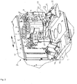
- the station box 1 denotes the station box of an IS machine, on which or on which a mold holding mechanism 2 is arranged.
- the station box 1 can be under overpressure, from which the cooling air supply is derived both for the molds and their mouth area, the cooling air guidance within the mold holding mechanism 2 being explained in more detail below.
- the mold holding mechanism 2 is designed, for example, to hold two molds 3, 4 intended for shaping hollow glass articles, each of which consists of two mold halves 5, 6 and 7, 8, respectively.
- the mold halves 5, 6, 7, 8 are carried by mold holders 9, 10, which are parallel within a housing section 11 with the participation of a drive, not shown in the drawing, in a horizontal plane in the direction of the arrows 12 between a closed position of the mold halves shown in the drawings and their open position are slidably arranged.
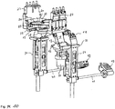
- 14 is the muzzle cooling, namely the connection of the cooling air supply intended for the muzzle area to the station housing 1 and 13 the mold cooling, namely the connection of the cooling air supply intended for the molds to the station housing 1, these connections being such that the Opening and closing movements of the mold halves 5, 6, 7, 8 are dependent on changes in distance and direction relative to the mold halves. This will be discussed in more detail below.
- the mold cooling 13 and the mouth cooling 14 are designed as 360 ° cooling systems. H. as cooling, which is effective uniformly during an entire cycle of an opening and closing movement of the mold halves 5 to 8.
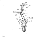
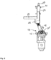
- the mold cooling 13 is characterized by a plate-like receptacle 15 which is arranged on the top 16 of the station housing 1 and which forms the link between a valve 17 arranged within the station housing 1 and a pivotably arranged cooling duct 18 with a rectangular cross section in the context of the cooling air duct.
- the cooling channel 18 ends on its side facing the receptacle 15 in a spherical guide body 19, which is received in a guide section 20 of the receptacle 15 corresponding to the profile, in this case representing a flow path for the cooling air, which leads from an air inlet 20 ′ through the guide section 19 leads into the cooling channel 18, wherein closing elements of the valve are arranged within this flow path.
- bearing cheeks are designated, which are integrally formed on the receptacle 15, in which the guide body 19 is rotatably supported on both sides about the axis 33 'by means of roller bearings. These roller bearings are completely enclosed within the bearing cheeks 32 and are lubricated for life.
- the end of the cooling channel 18 facing away from the receptacle 15 ends in a spherical bearing body 21 made of bronze, which lies sealingly on the inside of the inlet section 22, in this case representing a flow path into a cooling element 23, which ends in an arrangement of outlet slits 24 in the form of a ring section.
- the cooling channel 18 and the inlet section 22 are rectangular in cross section, so that during an opening or closing movement of the mold halves, the bearing body 21 executes a swiveling and sliding movement on the inside of the inlet section 22 to compensate for changes in length and angle.
- the fact that the bearing body 21 is arranged within a throttle housing 27 provides optimal protection of the sliding guide against the abrasive dirt occurring in the operating environment.
- valve 17, together with the housing including the cooling channel 18 mounted thereon, can remain in or on the station box 1, while the cooling element 23 remains on the mold holder of the closing mechanism.
- Said arrangement of the outlet slots 24 extends along a semicircle which is geometrically adapted to an arrangement of cooling air bores 25 which pass through the walls of each mold half 5 in an axis-parallel manner.
- the connection section 22 and the cooling piece 23 form part of an assembly 26, each of which carries a mold half 6 and is thus arranged to be movable in relation to the station box 1 in accordance with the opening and closing movements of the mold halves 5.
- Each mold half 6 is provided in its lower region with a step 46, which forms a horizontal annular segment surface, which is gripped by the cooling element 23, specifically in the region of the outlet slots 24 from which the cooling air emerges vertically and directly into the cooling air bores 25 Mold half 6 enters.
- Such cooling air holes 25 are provided along the entire circumference of the mold.
- the cooling piece 23 is secured on the step 46 by screws, so that it is easy to replace if necessary.
- the cooling piece 23 is preferably at a constant height in relation to the mold holder 9, so that no adaptation work is required when changing to a different mold height.
- the cooling piece 23 is preferably located in the lower half of the mold height, so that, depending on the respective blowing process, excessive cooling of the parison in the neck area, which at least impedes its elongation, is avoided.
- a stage of the assembly 26 is designated, which is located on the side facing the molds and on which the cooling element 23 is supported and secured with screws.
- a throttle housing is designated, which is also in connection with the assembly 26 and serves to accommodate a mechanism which is intended to change the flow cross section of the cooling air within the flow path between the connection section 22 and the cooling piece 23, here between a maximum and control a minimal opening.
- a blocking body 28 is provided, which can be displaced more or less into the flow cross-section mentioned by means of a spindle gear.
- Each of the spindle gears consists of a threaded spindle 29, which is operatively connected to an axially non-displaceably arranged spindle nut 30, the position of which can be fixed by means of a ball thrust piece 31 in defined locking positions, each corresponding to a specific flow cross section.
- each throttle housing 27 thus contains the means required for throttling the cooling air flow to form a mold half 5 to 8.
- Other divisions of the cooling air flow are also possible, for. B. an embodiment in which each throttle housing is assigned to half of a mold half 5 to 8.
- two threaded spindles 29 and thus two locking bodies 28 are assigned to each mold half 6.
- This grouping and likewise the constructive design of the drive of the locking bodies 28 can be varied as desired within the scope of the expert knowledge, but this will not be discussed in more detail. It is essential that, starting from an air inlet 20 via the valve 17, the line section 18, the connection section 22, the air distribution section 23, the outlet slots 24 and the cooling air bores 25, a continuous flow path for cooling the molds 3, 4 is shown, with the respective one Valve 17 a complete closure of the flow path can be represented and throttling of the cooling air flow can be achieved by actuating the blocking body 28.
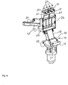
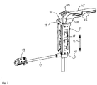
- the cooling structure 50 intended for the connection of the muzzle cooling is characterized by a base plate 33 on which a guide housing 34 which is suspended within the station box 1 is arranged.
- a structural unit which comprises a valve 37 and the cooling structure 50.
- the valve 37 and the cooling structure 50 are mounted on one another, so that flow-optimized lines for guiding cooling air are made available via the cooling structure 50, which end in outlet slots 35 on the side facing away from the base plate 33.
- the latter have a horizontal exit direction and are directed towards the mouth area of the respective shape.
- a cooling air flow to the mouth region of the mold can be completely blocked or opened via the valve 37.
- a throttle device 39 through the setting of which the cooling air flow reaching the mouth area can be reduced or increased.
- a cooling structure 38 having two outlet slots 35 is assigned to a mold half 5 as an example.
- the section 45 of the cooling structure 38 guiding the outlet slots 35 is held on the cooling structure 50 by a screw 44, so that an easy-to-assemble option is provided for replacing this section 45 when the shape changes due to the geometry or in the event of damage.
- the screw jack 40 with a screw jack is designated, which is connected via a drive shaft 41 to a drive 42, a stepper or servo motor, which protrudes from a rear wall 43 of the station box 1.
- the screw jack 40 is connected to the guide housing 34 and is used via a spindle shaft (not shown in the drawing) to adjust the height position of the outlet slots 35, so that the mouth region cooling according to the invention can be easily adapted to different mold heights. A height adjustment is thus possible by means of a motor-driven displacement of the cooling structure 38 in the direction of the arrows 36.
- a conversion to a different mold height can thus be carried out using an article database in which the height dimensions of different articles are stored. In this way, a simple and in particular quick conversion of the muzzle cooling to other mold heights can be carried out.
- the cooling piece 23 has a constant height in comparison to the mold holder 9, 10, so that in this respect no adaptation work is required when changing to a different mold height.
- the drive 42 protrudes from an opening in the end face 43 of the station box 1 and is arranged so that it is easily accessible. If necessary, it can be pulled out of the screw jack 40 together with the drive shaft 41 and used in the opposite direction.
- a centering aid can be provided in the station box 1 for simplified reinsertion into the screw jack 40.
- the screw jack 40 hangs on the underside of the guide housing 34 and is therefore located within the station box 1. It is therefore arranged to be protected against influences from the glass shaping process.
- the station box 1 can be under excess pressure to represent a cooling air supply. It can be seen that the valve 37 and in particular the screw jack 40 are arranged inside the station box 1 in a manner protected from abrasive environmental influences, in this case the glass manufacturing process.
- Fig. 10 shows the juxtaposition of the above-described components of the mold and the mouth cooling 13, 14 according to the invention.
- the mold-holding mechanism according to the invention provides a flexible, service-friendly system for guiding cooling air, which is characterized by independent controls of a muzzle cooling and a mold cooling.
Landscapes
- Engineering & Computer Science (AREA)
- Chemical & Material Sciences (AREA)
- Manufacturing & Machinery (AREA)
- Materials Engineering (AREA)
- Organic Chemistry (AREA)
- Moulds For Moulding Plastics Or The Like (AREA)
- Re-Forming, After-Treatment, Cutting And Transporting Of Glass Products (AREA)
Claims (17)
- Ensemble de refroidissement de moules et d'embouchures pour une machine à mouler le verre avec une boîte station (1), avec au moins un moule (3, 4) composé de deux moitiés de moule (5, 6, 7, 8), dans lequel les moitiés de moule sont disposées respectivement au niveau d'un système de maintien de moule (9, 10) et peuvent être déplacées au moyen d'un entraînement entre une position d'ouverture et une position de fermeture, dans lequel un système de refroidissement d'embouchures (13) et un système de refroidissement de moules (14) sont associés à chaque moule (3, 4), dans lequel une alimentation en air de refroidissement est installée à l'intérieur de la boîte station (1), dans lequel le système de refroidissement d'embouchures (13) ainsi que le système de refroidissement de moules (14) sont raccordés indépendamment l'un de l'autre ainsi qu'à des ouvertures, séparées les unes des autres, de la boîte station (1), dans lequel le système de refroidissement de moules (14) présente un canal de refroidissement (18), dont une extrémité est reliée de manière articulée à la boîte station (1), caractérisé en ce que l'autre extrémité du système de refroidissement de moules (14) est reliée de manière articulée et de manière à permettre également une compensation de longueur à un module (26), qui est maintenu quant à lui par un système de maintien de moule (8, 9), avec une pièce de refroidissement (23) formant un organe de lien avec au moins une moitié de moule (5, 6, 7, 8), relié de manière amovible au module (26), que le canal de refroidissement (18) est logé de manière à pouvoir pivoter autour d'un axe horizontal (33') au niveau de son extrémité tournée vers la boîte station (1) et de manière à pouvoir glisser dans une section de raccordement (22) du module (26) au niveau de son extrémité opposée à la boîte station (1).
- Ensemble de refroidissement de moules et d'embouchures selon la revendication 1, caractérisé en ce que l'autre extrémité évoquée du canal de refroidissement (18) est enfichée dans une section de raccordement (22) du module (26).
- Ensemble de refroidissement de moules et d'embouchures selon l'une quelconque des revendications 1 ou 2, caractérisé en ce que le module (26) est relié de manière amovible à un système de maintien de moule (9, 10) et comprend un boîtier d'étranglement (27), lequel est équipé de moyens pour modifier le flux d'air de refroidissement du système de refroidissement de moules (14).
- Ensemble de refroidissement de moules et d'embouchures selon la revendication 3, caractérisé en ce que les moyens mentionnés sont représentés par un corps de fermeture (28), qui peut être poussé sur une voie d'écoulement du flux d'air de refroidissement de manière à modifier la section transversale de ce dernier.
- Ensemble de refroidissement de moules et d'embouchures selon l'une quelconque des revendications 1 à 4, caractérisé en ce que le canal de refroidissement (18) présente une section transversale rectangulaire et est en liaison fonctionnelle avec la boîte station (1) par l'intermédiaire d'une soupape (17) .
- Ensemble de refroidissement de moules et d'embouchures selon l'une quelconque des revendications 1 à 5, caractérisé en ce que la pièce de refroidissement (23) présente un ensemble de sorties d'air (24) avec une direction de sortie orientée de manière perpendiculaire, et que la partie, supportant les sorties d'air (24), de la pièce de refroidissement (23) est mise au point pour venir en prise par en bas avec un étage (46) d'une moitié de moule (5, 6, 7, 8), formant dans le cas présent respectivement des voies d'écoulement continues avec les alésages d'air de refroidissement (25) des moitiés de moule (5, 6, 7, 8).
- Ensemble de refroidissement de moules et d'embouchures selon la revendication 6, caractérisé en ce que l'étage (46) se trouve dans la zone de la moitié inférieure de la hauteur d'une moitié de moule (5, 6, 7, 8) .
- Ensemble de refroidissement de moules et d'embouchures selon l'une quelconque des revendications 1 à 7, caractérisé en ce que la pièce de refroidissement (23) est déposée sur un étage (47) du module (26) et est reliée à celui-ci de manière amovible.
- Ensemble de refroidissement de moules et d'embouchures selon l'une quelconque des revendications 1 à 8, caractérisé en ce que la pièce de refroidissement (23) se trouve sur une position en hauteur fixe par rapport au système de support de moule (9, 10).
- Ensemble de refroidissement de moules et d'embouchures selon l'une quelconque des revendications 1 à 9, caractérisé en ce que le système de refroidissement d'embouchures (13) présente une structure de refroidissement (38) disposée en partie à l'intérieur de la boîte station (1), supportant une soupape (37), qui présente au niveau de son extrémité opposée à la boîte station (1) des entailles de sortie (35) .
- Ensemble de refroidissement de moules et d'embouchures selon la revendication 10, caractérisé en ce que la structure de refroidissement (38) présente au niveau de son extrémité tournée vers les entailles de sortie (35) une section (45) disposée de manière amovible, supportant les entailles de sortie (35).
- Ensemble de refroidissement de moules et d'embouchures selon la revendication 10 ou 11, caractérisé en ce que la structure de refroidissement (38) est disposée de manière ajustable en hauteur par rapport à la boîte station (1).
- Ensemble de refroidissement de moules et d'embouchures selon l'une quelconque des revendications 10 à 12, caractérisé en ce que les entailles de sortie (35) présentent une direction d'écoulement sortant horizontale.
- Ensemble de refroidissement de moules et d'embouchures selon l'une quelconque des revendications 11 à 13, caractérisé en ce que la structure de refroidissement (38) est disposée de manière ajustable en hauteur à l'intérieur d'un boîtier de guidage (34), que le boîtier de guidage (34) est relié à la boîte station (1), et qu'est prévu, pour représenter l'ajustabilité en hauteur, un vérin de levage (40), lequel est relié par l'intermédiaire d'un arbre d'entraînement (41) à un entraînement (42).
- Ensemble de refroidissement de moules et d'embouchures selon la revendication 14, caractérisé en ce que l'entraînement (42) est disposé côté extérieur au niveau de la boîte station (1).
- Ensemble de refroidissement de moules et d'embouchures selon la revendication 14 ou 15, caractérisé par une base de données d'articles, dans laquelle différentes mesures de hauteur des moules (3, 4) employés sont mémorisées et qui est en liaison fonctionnelle avec l'entraînement (42).
- Ensemble de refroidissement de moules et d'embouchures selon l'une quelconque des revendications 1 à 16, caractérisé en ce que des équipements pour l'étranglement du flux d'air de refroidissement sont disposés à l'intérieur des voies d'écoulement mises au point pour le système de refroidissement d'embouchures (13) pour l'air de refroidissement.
Priority Applications (1)
| Application Number | Priority Date | Filing Date | Title |
|---|---|---|---|
| PL17757685T PL3510001T3 (pl) | 2016-09-09 | 2017-08-07 | Układ chłodzenia formy i ujścia przeznaczony do maszyny do formowania wyrobów szklanych |
Applications Claiming Priority (2)
| Application Number | Priority Date | Filing Date | Title |
|---|---|---|---|
| DE102016010802.9A DE102016010802A1 (de) | 2016-09-09 | 2016-09-09 | Form- und Mündungskühlungsanordnung für eine Glasformmaschine |
| PCT/EP2017/000957 WO2018046114A1 (fr) | 2016-09-09 | 2017-08-07 | Dispositif de refroidissement de moules et d'embouchures pour une machine à mouler le verre |
Publications (2)
| Publication Number | Publication Date |
|---|---|
| EP3510001A1 EP3510001A1 (fr) | 2019-07-17 |
| EP3510001B1 true EP3510001B1 (fr) | 2020-07-15 |
Family
ID=59702661
Family Applications (1)
| Application Number | Title | Priority Date | Filing Date |
|---|---|---|---|
| EP17757685.7A Active EP3510001B1 (fr) | 2016-09-09 | 2017-08-07 | Dispositif de refroidissement de moules et d'embouchures pour une machine à mouler le verre |
Country Status (9)
| Country | Link |
|---|---|
| US (1) | US10696577B2 (fr) |
| EP (1) | EP3510001B1 (fr) |
| AU (1) | AU2017301080B2 (fr) |
| DE (1) | DE102016010802A1 (fr) |
| ES (1) | ES2818651T3 (fr) |
| MX (1) | MX384730B (fr) |
| PL (1) | PL3510001T3 (fr) |
| PT (1) | PT3510001T (fr) |
| WO (1) | WO2018046114A1 (fr) |
Families Citing this family (3)
| Publication number | Priority date | Publication date | Assignee | Title |
|---|---|---|---|---|
| DE102017130920B4 (de) * | 2017-12-21 | 2020-02-06 | Getrag Ford Transmissions Gmbh | Aktuatoranordnung für einen Kraftfahrzeugantriebsstrang und Verfahren zu dessen Betreiben |
| CN113277713B (zh) * | 2021-06-25 | 2022-02-15 | 成都光明光电有限责任公司 | 玻璃成型装置及大口径掺钕磷酸盐激光玻璃的成型方法 |
| CN119108709B (zh) * | 2024-11-11 | 2025-02-28 | 深圳市瑞能电源科技有限公司 | 一种温度可调的电池组件和系统 |
Family Cites Families (5)
| Publication number | Priority date | Publication date | Assignee | Title |
|---|---|---|---|---|
| US5304229A (en) * | 1990-11-13 | 1994-04-19 | I.M.T.E.C. Enterprises, Inc. | Glassware forming machine with cooling system |
| US5330551A (en) | 1992-12-02 | 1994-07-19 | I.M.T.E.C. Enterprises, Inc. | Glassware forming machine with cooling system |
| DE10020431B4 (de) | 2000-04-26 | 2005-03-10 | Gps Glasprod Serv Gmbh | Kühlvorrichtung für eine mit einer Mündungsform versehene Vorform einer IS-Glasmaschine |
| US20060179884A1 (en) * | 2003-12-17 | 2006-08-17 | Difrank Frank J | Glassware forming machine mold cooling apparatus and method |
| DE102014008534B4 (de) * | 2014-06-16 | 2018-03-22 | Heye International Gmbh | Schließmechanismus für die Formhälfte einer I.S.-Maschine |
-
2016
- 2016-09-09 DE DE102016010802.9A patent/DE102016010802A1/de not_active Withdrawn
-
2017
- 2017-08-07 US US15/752,311 patent/US10696577B2/en active Active
- 2017-08-07 WO PCT/EP2017/000957 patent/WO2018046114A1/fr not_active Ceased
- 2017-08-07 EP EP17757685.7A patent/EP3510001B1/fr active Active
- 2017-08-07 PT PT177576857T patent/PT3510001T/pt unknown
- 2017-08-07 MX MX2018001377A patent/MX384730B/es unknown
- 2017-08-07 PL PL17757685T patent/PL3510001T3/pl unknown
- 2017-08-07 ES ES17757685T patent/ES2818651T3/es active Active
- 2017-08-07 AU AU2017301080A patent/AU2017301080B2/en active Active
Non-Patent Citations (1)
| Title |
|---|
| None * |
Also Published As
| Publication number | Publication date |
|---|---|
| MX2018001377A (es) | 2018-06-15 |
| US10696577B2 (en) | 2020-06-30 |
| BR112018001408A2 (pt) | 2018-09-11 |
| WO2018046114A1 (fr) | 2018-03-15 |
| AU2017301080A1 (en) | 2018-03-29 |
| MX384730B (es) | 2025-03-14 |
| EP3510001A1 (fr) | 2019-07-17 |
| PT3510001T (pt) | 2020-09-15 |
| DE102016010802A1 (de) | 2018-03-15 |
| US20200095153A1 (en) | 2020-03-26 |
| AU2017301080B2 (en) | 2021-06-17 |
| ES2818651T3 (es) | 2021-04-13 |
| PL3510001T3 (pl) | 2021-05-31 |
Similar Documents
| Publication | Publication Date | Title |
|---|---|---|
| DE102007012779B4 (de) | IS-Glasbehälterformmaschine mit Formenkühlung | |
| DE102010048560B3 (de) | Spritzgießmaschine mit wenigstens zwei Kniehebelmechanismen | |
| EP0052223B1 (fr) | Appareil pour le refroidissement d'un moule de formage | |
| DE69516617T2 (de) | Vorrichtung und Verfahren zum Blasformen von dreidimensionalen Gegenständen | |
| EP3510001B1 (fr) | Dispositif de refroidissement de moules et d'embouchures pour une machine à mouler le verre | |
| DE2623106B2 (de) | LS. Glaswarenformmaschine mit geradliniger Bewegung der Formen | |
| EP2384980B1 (fr) | Station de travail pour machine d'emballage | |
| DE102010050204B4 (de) | Baueinheit zum Überführen einer Komponente zwischen zwei Stellungen | |
| DE69208082T2 (de) | Verfahren und Vorrichtung zum Kühlen einer Matrize | |
| DE3346466A1 (de) | Vorrichtung zum gleichzeitigen oeffnen und schliessen von mehreren parison-formen in einem begrenzten raum | |
| EP0542935B1 (fr) | Dispositif pour le refroidissement des moules de sortie d'une machine a mouler le verre | |
| DE1596581A1 (de) | Glasformmaschine | |
| DE202019100162U1 (de) | Spritzgusswerkzeug für die Herstellung von Behältern aus Kunststoff | |
| DE69509946T2 (de) | Formmechanismus | |
| DE4022530A1 (de) | Duese fuer spritzgiessmaschinen | |
| DE2626337A1 (de) | Glasformmaschine | |
| EP2230217B1 (fr) | Station d'ébauche d'une machine IS | |
| DE2500185C2 (de) | Blasformmaschine | |
| EP1477292B1 (fr) | Buse d'injection pour presses à injecter | |
| EP1149806B1 (fr) | Dispositif de refroidissement d' un moule ébaucher pourvu d' un moule de bague dans une machine I.S | |
| DE19922684C2 (de) | Blasformmaschine für das abfallarme Blasen | |
| DE3040356C1 (de) | Vorrichtung zur Verteilung von Kuehlfluid ueber ein Formwerkzeug einer Maschine zur Verarbeitung von schmelzfluessigem Glas oder aehnlichen thermoplastischen Stoffen | |
| WO1998019849A1 (fr) | Dispositif pour verrouiller et ouvrir un moule pour injection | |
| DE102016010892B4 (de) | Glasformmaschine | |
| DE8916021U1 (de) | Vorrichtung zum Kühlen der Form oder der Formen einer IS- oder RIS-Maschine zur Herstellung von Hohlglasartikeln |
Legal Events
| Date | Code | Title | Description |
|---|---|---|---|
| STAA | Information on the status of an ep patent application or granted ep patent |
Free format text: STATUS: UNKNOWN |
|
| STAA | Information on the status of an ep patent application or granted ep patent |
Free format text: STATUS: THE INTERNATIONAL PUBLICATION HAS BEEN MADE |
|
| PUAI | Public reference made under article 153(3) epc to a published international application that has entered the european phase |
Free format text: ORIGINAL CODE: 0009012 |
|
| STAA | Information on the status of an ep patent application or granted ep patent |
Free format text: STATUS: REQUEST FOR EXAMINATION WAS MADE |
|
| 17P | Request for examination filed |
Effective date: 20171212 |
|
| AK | Designated contracting states |
Kind code of ref document: A1 Designated state(s): AL AT BE BG CH CY CZ DE DK EE ES FI FR GB GR HR HU IE IS IT LI LT LU LV MC MK MT NL NO PL PT RO RS SE SI SK SM TR |
|
| AX | Request for extension of the european patent |
Extension state: BA ME |
|
| DAV | Request for validation of the european patent (deleted) | ||
| DAX | Request for extension of the european patent (deleted) | ||
| GRAP | Despatch of communication of intention to grant a patent |
Free format text: ORIGINAL CODE: EPIDOSNIGR1 |
|
| STAA | Information on the status of an ep patent application or granted ep patent |
Free format text: STATUS: GRANT OF PATENT IS INTENDED |
|
| INTG | Intention to grant announced |
Effective date: 20200320 |
|
| GRAJ | Information related to disapproval of communication of intention to grant by the applicant or resumption of examination proceedings by the epo deleted |
Free format text: ORIGINAL CODE: EPIDOSDIGR1 |
|
| STAA | Information on the status of an ep patent application or granted ep patent |
Free format text: STATUS: REQUEST FOR EXAMINATION WAS MADE |
|
| GRAJ | Information related to disapproval of communication of intention to grant by the applicant or resumption of examination proceedings by the epo deleted |
Free format text: ORIGINAL CODE: EPIDOSDIGR1 |
|
| GRAL | Information related to payment of fee for publishing/printing deleted |
Free format text: ORIGINAL CODE: EPIDOSDIGR3 |
|
| GRAR | Information related to intention to grant a patent recorded |
Free format text: ORIGINAL CODE: EPIDOSNIGR71 |
|
| GRAS | Grant fee paid |
Free format text: ORIGINAL CODE: EPIDOSNIGR3 |
|
| STAA | Information on the status of an ep patent application or granted ep patent |
Free format text: STATUS: GRANT OF PATENT IS INTENDED |
|
| GRAA | (expected) grant |
Free format text: ORIGINAL CODE: 0009210 |
|
| STAA | Information on the status of an ep patent application or granted ep patent |
Free format text: STATUS: THE PATENT HAS BEEN GRANTED |
|
| INTC | Intention to grant announced (deleted) | ||
| INTG | Intention to grant announced |
Effective date: 20200604 |
|
| AK | Designated contracting states |
Kind code of ref document: B1 Designated state(s): AL AT BE BG CH CY CZ DE DK EE ES FI FR GB GR HR HU IE IS IT LI LT LU LV MC MK MT NL NO PL PT RO RS SE SI SK SM TR |
|
| REG | Reference to a national code |
Ref country code: CH Ref legal event code: EP Ref country code: GB Ref legal event code: FG4D Free format text: NOT ENGLISH |
|
| REG | Reference to a national code |
Ref country code: IE Ref legal event code: FG4D Free format text: LANGUAGE OF EP DOCUMENT: GERMAN |
|
| REG | Reference to a national code |
Ref country code: DE Ref legal event code: R096 Ref document number: 502017006245 Country of ref document: DE |
|
| REG | Reference to a national code |
Ref country code: AT Ref legal event code: REF Ref document number: 1290852 Country of ref document: AT Kind code of ref document: T Effective date: 20200815 |
|
| REG | Reference to a national code |
Ref country code: PT Ref legal event code: SC4A Ref document number: 3510001 Country of ref document: PT Date of ref document: 20200915 Kind code of ref document: T Free format text: AVAILABILITY OF NATIONAL TRANSLATION Effective date: 20200908 |
|
| REG | Reference to a national code |
Ref country code: SE Ref legal event code: TRGR |
|
| REG | Reference to a national code |
Ref country code: LT Ref legal event code: MG4D |
|
| REG | Reference to a national code |
Ref country code: NL Ref legal event code: MP Effective date: 20200715 |
|
| PG25 | Lapsed in a contracting state [announced via postgrant information from national office to epo] |
Ref country code: GR Free format text: LAPSE BECAUSE OF FAILURE TO SUBMIT A TRANSLATION OF THE DESCRIPTION OR TO PAY THE FEE WITHIN THE PRESCRIBED TIME-LIMIT Effective date: 20201016 Ref country code: BG Free format text: LAPSE BECAUSE OF FAILURE TO SUBMIT A TRANSLATION OF THE DESCRIPTION OR TO PAY THE FEE WITHIN THE PRESCRIBED TIME-LIMIT Effective date: 20201015 Ref country code: HR Free format text: LAPSE BECAUSE OF FAILURE TO SUBMIT A TRANSLATION OF THE DESCRIPTION OR TO PAY THE FEE WITHIN THE PRESCRIBED TIME-LIMIT Effective date: 20200715 Ref country code: LT Free format text: LAPSE BECAUSE OF FAILURE TO SUBMIT A TRANSLATION OF THE DESCRIPTION OR TO PAY THE FEE WITHIN THE PRESCRIBED TIME-LIMIT Effective date: 20200715 Ref country code: FI Free format text: LAPSE BECAUSE OF FAILURE TO SUBMIT A TRANSLATION OF THE DESCRIPTION OR TO PAY THE FEE WITHIN THE PRESCRIBED TIME-LIMIT Effective date: 20200715 Ref country code: NO Free format text: LAPSE BECAUSE OF FAILURE TO SUBMIT A TRANSLATION OF THE DESCRIPTION OR TO PAY THE FEE WITHIN THE PRESCRIBED TIME-LIMIT Effective date: 20201015 |
|
| PG25 | Lapsed in a contracting state [announced via postgrant information from national office to epo] |
Ref country code: RS Free format text: LAPSE BECAUSE OF FAILURE TO SUBMIT A TRANSLATION OF THE DESCRIPTION OR TO PAY THE FEE WITHIN THE PRESCRIBED TIME-LIMIT Effective date: 20200715 Ref country code: LV Free format text: LAPSE BECAUSE OF FAILURE TO SUBMIT A TRANSLATION OF THE DESCRIPTION OR TO PAY THE FEE WITHIN THE PRESCRIBED TIME-LIMIT Effective date: 20200715 Ref country code: IS Free format text: LAPSE BECAUSE OF FAILURE TO SUBMIT A TRANSLATION OF THE DESCRIPTION OR TO PAY THE FEE WITHIN THE PRESCRIBED TIME-LIMIT Effective date: 20201115 |
|
| PG25 | Lapsed in a contracting state [announced via postgrant information from national office to epo] |
Ref country code: NL Free format text: LAPSE BECAUSE OF FAILURE TO SUBMIT A TRANSLATION OF THE DESCRIPTION OR TO PAY THE FEE WITHIN THE PRESCRIBED TIME-LIMIT Effective date: 20200715 |
|
| REG | Reference to a national code |
Ref country code: ES Ref legal event code: FG2A Ref document number: 2818651 Country of ref document: ES Kind code of ref document: T3 Effective date: 20210413 |
|
| REG | Reference to a national code |
Ref country code: DE Ref legal event code: R097 Ref document number: 502017006245 Country of ref document: DE |
|
| PG25 | Lapsed in a contracting state [announced via postgrant information from national office to epo] |
Ref country code: LU Free format text: LAPSE BECAUSE OF NON-PAYMENT OF DUE FEES Effective date: 20200807 Ref country code: RO Free format text: LAPSE BECAUSE OF FAILURE TO SUBMIT A TRANSLATION OF THE DESCRIPTION OR TO PAY THE FEE WITHIN THE PRESCRIBED TIME-LIMIT Effective date: 20200715 Ref country code: DK Free format text: LAPSE BECAUSE OF FAILURE TO SUBMIT A TRANSLATION OF THE DESCRIPTION OR TO PAY THE FEE WITHIN THE PRESCRIBED TIME-LIMIT Effective date: 20200715 Ref country code: EE Free format text: LAPSE BECAUSE OF FAILURE TO SUBMIT A TRANSLATION OF THE DESCRIPTION OR TO PAY THE FEE WITHIN THE PRESCRIBED TIME-LIMIT Effective date: 20200715 Ref country code: SM Free format text: LAPSE BECAUSE OF FAILURE TO SUBMIT A TRANSLATION OF THE DESCRIPTION OR TO PAY THE FEE WITHIN THE PRESCRIBED TIME-LIMIT Effective date: 20200715 |
|
| PLBE | No opposition filed within time limit |
Free format text: ORIGINAL CODE: 0009261 |
|
| STAA | Information on the status of an ep patent application or granted ep patent |
Free format text: STATUS: NO OPPOSITION FILED WITHIN TIME LIMIT |
|
| REG | Reference to a national code |
Ref country code: BE Ref legal event code: MM Effective date: 20200831 |
|
| PG25 | Lapsed in a contracting state [announced via postgrant information from national office to epo] |
Ref country code: AL Free format text: LAPSE BECAUSE OF FAILURE TO SUBMIT A TRANSLATION OF THE DESCRIPTION OR TO PAY THE FEE WITHIN THE PRESCRIBED TIME-LIMIT Effective date: 20200715 |
|
| 26N | No opposition filed |
Effective date: 20210416 |
|
| PG25 | Lapsed in a contracting state [announced via postgrant information from national office to epo] |
Ref country code: SK Free format text: LAPSE BECAUSE OF FAILURE TO SUBMIT A TRANSLATION OF THE DESCRIPTION OR TO PAY THE FEE WITHIN THE PRESCRIBED TIME-LIMIT Effective date: 20200715 |
|
| PG25 | Lapsed in a contracting state [announced via postgrant information from national office to epo] |
Ref country code: BE Free format text: LAPSE BECAUSE OF NON-PAYMENT OF DUE FEES Effective date: 20200831 Ref country code: SI Free format text: LAPSE BECAUSE OF FAILURE TO SUBMIT A TRANSLATION OF THE DESCRIPTION OR TO PAY THE FEE WITHIN THE PRESCRIBED TIME-LIMIT Effective date: 20200715 Ref country code: IE Free format text: LAPSE BECAUSE OF NON-PAYMENT OF DUE FEES Effective date: 20200807 |
|
| PG25 | Lapsed in a contracting state [announced via postgrant information from national office to epo] |
Ref country code: TR Free format text: LAPSE BECAUSE OF FAILURE TO SUBMIT A TRANSLATION OF THE DESCRIPTION OR TO PAY THE FEE WITHIN THE PRESCRIBED TIME-LIMIT Effective date: 20200715 Ref country code: MT Free format text: LAPSE BECAUSE OF FAILURE TO SUBMIT A TRANSLATION OF THE DESCRIPTION OR TO PAY THE FEE WITHIN THE PRESCRIBED TIME-LIMIT Effective date: 20200715 Ref country code: CY Free format text: LAPSE BECAUSE OF FAILURE TO SUBMIT A TRANSLATION OF THE DESCRIPTION OR TO PAY THE FEE WITHIN THE PRESCRIBED TIME-LIMIT Effective date: 20200715 |
|
| PG25 | Lapsed in a contracting state [announced via postgrant information from national office to epo] |
Ref country code: MK Free format text: LAPSE BECAUSE OF FAILURE TO SUBMIT A TRANSLATION OF THE DESCRIPTION OR TO PAY THE FEE WITHIN THE PRESCRIBED TIME-LIMIT Effective date: 20200715 Ref country code: MC Free format text: LAPSE BECAUSE OF FAILURE TO SUBMIT A TRANSLATION OF THE DESCRIPTION OR TO PAY THE FEE WITHIN THE PRESCRIBED TIME-LIMIT Effective date: 20200715 |
|
| P01 | Opt-out of the competence of the unified patent court (upc) registered |
Effective date: 20230526 |
|
| PGFP | Annual fee paid to national office [announced via postgrant information from national office to epo] |
Ref country code: ES Payment date: 20250926 Year of fee payment: 9 Ref country code: PT Payment date: 20250724 Year of fee payment: 9 |
|
| PGFP | Annual fee paid to national office [announced via postgrant information from national office to epo] |
Ref country code: DE Payment date: 20250827 Year of fee payment: 9 |
|
| PGFP | Annual fee paid to national office [announced via postgrant information from national office to epo] |
Ref country code: PL Payment date: 20250722 Year of fee payment: 9 Ref country code: IT Payment date: 20250825 Year of fee payment: 9 |
|
| PGFP | Annual fee paid to national office [announced via postgrant information from national office to epo] |
Ref country code: GB Payment date: 20250821 Year of fee payment: 9 |
|
| PGFP | Annual fee paid to national office [announced via postgrant information from national office to epo] |
Ref country code: AT Payment date: 20250821 Year of fee payment: 9 Ref country code: FR Payment date: 20250828 Year of fee payment: 9 |
|
| PGFP | Annual fee paid to national office [announced via postgrant information from national office to epo] |
Ref country code: SE Payment date: 20250820 Year of fee payment: 9 Ref country code: CH Payment date: 20250901 Year of fee payment: 9 |
|
| PGFP | Annual fee paid to national office [announced via postgrant information from national office to epo] |
Ref country code: CZ Payment date: 20250725 Year of fee payment: 9 |