EP3510202B1 - Überschlagverhinderungssystem und verfahren für eine baumaschine - Google Patents
Überschlagverhinderungssystem und verfahren für eine baumaschine Download PDFInfo
- Publication number
- EP3510202B1 EP3510202B1 EP16915477.0A EP16915477A EP3510202B1 EP 3510202 B1 EP3510202 B1 EP 3510202B1 EP 16915477 A EP16915477 A EP 16915477A EP 3510202 B1 EP3510202 B1 EP 3510202B1
- Authority
- EP
- European Patent Office
- Prior art keywords
- barycenter
- construction machine
- axis
- swing
- upper frame
- Prior art date
- Legal status (The legal status is an assumption and is not a legal conclusion. Google has not performed a legal analysis and makes no representation as to the accuracy of the status listed.)
- Active
Links
Images


Classifications
-
- E—FIXED CONSTRUCTIONS
- E02—HYDRAULIC ENGINEERING; FOUNDATIONS; SOIL SHIFTING
- E02F—DREDGING; SOIL-SHIFTING
- E02F9/00—Component parts of dredgers or soil-shifting machines, not restricted to one of the kinds covered by groups E02F3/00 - E02F7/00
- E02F9/20—Drives; Control devices
- E02F9/2025—Particular purposes of control systems not otherwise provided for
- E02F9/2033—Limiting the movement of frames or implements, e.g. to avoid collision between implements and the cabin
-
- E—FIXED CONSTRUCTIONS
- E02—HYDRAULIC ENGINEERING; FOUNDATIONS; SOIL SHIFTING
- E02F—DREDGING; SOIL-SHIFTING
- E02F9/00—Component parts of dredgers or soil-shifting machines, not restricted to one of the kinds covered by groups E02F3/00 - E02F7/00
- E02F9/20—Drives; Control devices
- E02F9/22—Hydraulic or pneumatic drives
- E02F9/2278—Hydraulic circuits
- E02F9/2285—Pilot-operated systems
-
- B—PERFORMING OPERATIONS; TRANSPORTING
- B60—VEHICLES IN GENERAL
- B60Q—ARRANGEMENT OF SIGNALLING OR LIGHTING DEVICES, THE MOUNTING OR SUPPORTING THEREOF OR CIRCUITS THEREFOR, FOR VEHICLES IN GENERAL
- B60Q5/00—Arrangement or adaptation of acoustic signal devices
- B60Q5/005—Arrangement or adaptation of acoustic signal devices automatically actuated
-
- E—FIXED CONSTRUCTIONS
- E02—HYDRAULIC ENGINEERING; FOUNDATIONS; SOIL SHIFTING
- E02F—DREDGING; SOIL-SHIFTING
- E02F9/00—Component parts of dredgers or soil-shifting machines, not restricted to one of the kinds covered by groups E02F3/00 - E02F7/00
- E02F9/20—Drives; Control devices
- E02F9/22—Hydraulic or pneumatic drives
- E02F9/2221—Control of flow rate; Load sensing arrangements
- E02F9/2225—Control of flow rate; Load sensing arrangements using pressure-compensating valves
- E02F9/2228—Control of flow rate; Load sensing arrangements using pressure-compensating valves including an electronic controller
-
- E—FIXED CONSTRUCTIONS
- E02—HYDRAULIC ENGINEERING; FOUNDATIONS; SOIL SHIFTING
- E02F—DREDGING; SOIL-SHIFTING
- E02F9/00—Component parts of dredgers or soil-shifting machines, not restricted to one of the kinds covered by groups E02F3/00 - E02F7/00
- E02F9/20—Drives; Control devices
- E02F9/22—Hydraulic or pneumatic drives
- E02F9/2278—Hydraulic circuits
- E02F9/2292—Systems with two or more pumps
-
- E—FIXED CONSTRUCTIONS
- E02—HYDRAULIC ENGINEERING; FOUNDATIONS; SOIL SHIFTING
- E02F—DREDGING; SOIL-SHIFTING
- E02F9/00—Component parts of dredgers or soil-shifting machines, not restricted to one of the kinds covered by groups E02F3/00 - E02F7/00
- E02F9/24—Safety devices, e.g. for preventing overload
-
- E—FIXED CONSTRUCTIONS
- E02—HYDRAULIC ENGINEERING; FOUNDATIONS; SOIL SHIFTING
- E02F—DREDGING; SOIL-SHIFTING
- E02F9/00—Component parts of dredgers or soil-shifting machines, not restricted to one of the kinds covered by groups E02F3/00 - E02F7/00
- E02F9/26—Indicating devices
-
- E—FIXED CONSTRUCTIONS
- E02—HYDRAULIC ENGINEERING; FOUNDATIONS; SOIL SHIFTING
- E02F—DREDGING; SOIL-SHIFTING
- E02F9/00—Component parts of dredgers or soil-shifting machines, not restricted to one of the kinds covered by groups E02F3/00 - E02F7/00
- E02F9/26—Indicating devices
- E02F9/264—Sensors and their calibration for indicating the position of the work tool
-
- E—FIXED CONSTRUCTIONS
- E02—HYDRAULIC ENGINEERING; FOUNDATIONS; SOIL SHIFTING
- E02F—DREDGING; SOIL-SHIFTING
- E02F9/00—Component parts of dredgers or soil-shifting machines, not restricted to one of the kinds covered by groups E02F3/00 - E02F7/00
- E02F9/26—Indicating devices
- E02F9/264—Sensors and their calibration for indicating the position of the work tool
- E02F9/265—Sensors and their calibration for indicating the position of the work tool with follow-up actions (e.g. control signals sent to actuate the work tool)
-
- E—FIXED CONSTRUCTIONS
- E02—HYDRAULIC ENGINEERING; FOUNDATIONS; SOIL SHIFTING
- E02F—DREDGING; SOIL-SHIFTING
- E02F3/00—Dredgers; Soil-shifting machines
- E02F3/04—Dredgers; Soil-shifting machines mechanically-driven
- E02F3/28—Dredgers; Soil-shifting machines mechanically-driven with digging tools mounted on a dipper- or bucket-arm, i.e. there is either one arm or a pair of arms, e.g. dippers, buckets
- E02F3/30—Dredgers; Soil-shifting machines mechanically-driven with digging tools mounted on a dipper- or bucket-arm, i.e. there is either one arm or a pair of arms, e.g. dippers, buckets with a dipper-arm pivoted on a cantilever beam, i.e. boom
- E02F3/32—Dredgers; Soil-shifting machines mechanically-driven with digging tools mounted on a dipper- or bucket-arm, i.e. there is either one arm or a pair of arms, e.g. dippers, buckets with a dipper-arm pivoted on a cantilever beam, i.e. boom working downwardly and towards the machine, e.g. with backhoes
-
- E—FIXED CONSTRUCTIONS
- E02—HYDRAULIC ENGINEERING; FOUNDATIONS; SOIL SHIFTING
- E02F—DREDGING; SOIL-SHIFTING
- E02F9/00—Component parts of dredgers or soil-shifting machines, not restricted to one of the kinds covered by groups E02F3/00 - E02F7/00
- E02F9/20—Drives; Control devices
- E02F9/22—Hydraulic or pneumatic drives
- E02F9/2278—Hydraulic circuits
- E02F9/2296—Systems with a variable displacement pump
Definitions
- the present disclosure relates to a rollover prevention system and method for a construction machine. More particularly, the present disclosure relates to a rollover prevention system and method for a construction machine, the system and method able to alarm an operator while blocking the supply of working oil to prevent the construction machine from rolling over or tipping when the barycenter of the construction machine deviates from a safety range or enters a critical range during excavation in a construction place or on a slope.
- the barycenter of the construction machine In the operation of a construction machine such as an excavator or a wheel loader, the barycenter of the construction machine variously changes. In particular, during excavation or digging on a slope or in an operation of carrying payloads containing a large amount of rock that causes an excessive load, the barycenter of the construction machine may deviate from an allowable safety range, leading to rollover.
- a construction machine is safer when the barycenter of the construction machine is closer to the swing axis of an upper frame or an upper swing structure.
- the degree of safety decreases and, the risk of rollover increases.
- An operator in a cab cannot recognize a change in the barycenter of the construction machine.
- the movement of a work attachment for excavation or digging is still allowed by the operator. Since the work attachment moves during the operation, the barycenter of the construction machine becomes unstable.
- United Sates Patent No. 8,768,581 disclosed "WORK MACHINE SAFETY DEVICE.” This patent is intended to prevent the rollover of equipment using ZMP calculating means.
- this patent is not intended to automatically or forcibly restrict the movement of a work attachment or equipment when the risk of rollover is increased by the barycenter deviating from a safety range.
- construction machines require a function able to prevent rollover by alarming operators with information regarding the barycenter and forcibly restrain the movement of construction machines when the risk of rollover is increased by the deviation of the barycenter during operation.
- JP H07 207711 A relates to an electrically-driven turning/swing device equipped with a revolving superstructure to which an attachment is attached in the base so that turning is possible.
- the electrically-driven turning/swing device has a function which prevents a fall at the time when operating at a sloping ground.
- a rollover prevention system for a construction machine may include:
- the safety valves may include a first safety valve disposed on one of the flow passages to block a flow of oil supplied from the first hydraulic pump and a second safety valve disposed on the other of the flow passages to block a flow of oil supplied from the second hydraulic pump.
- a rollover prevention method for a construction machine is defined in claim 9.
- FIG. 1 is a perspective view illustrating an excavator to which the present disclosure is applied.
- the excavator includes an undercarriage 1 traveling on the surface of the ground using endless tracks and an upper frame 5 rotatably mounted on the undercarriage 1.
- An upper swing structure 6 including a work attachment 10 is provided on the upper frame 5.
- the work attachment 10 includes a boom 2, the proximal portion of which is pivotably connected to the upper frame 5, an arm 3 pivotably connected to the distal portion of the boom 2, and a bucket 4 pivotably connected to the distal portion of the arm 3.
- the bucket 4 is fixed to the distal portion of the arm 3 using a bucket fixing pin 7a such that the bucket 4 can pivot about the bucket fixing pin 7a.
- the proximal portion of the arm 3 is fixed to the distal portion of the boom 2 using an arm fixing pin 7b such that the arm 3 can pivot about the arm fixing pin 7b.
- the proximal portion of the boom 2 is fixed to the upper frame 5 using a boom fixing pin 7c such that the boom 2 can pivot about the boom fixing pin 7c.
- the boom 2 is driven in response to the extension and contraction of a boom cylinder 8.
- the arm 3 and the bucket 4 are driven in response to the extension and contraction of an arm cylinder 9 and a bucket cylinder 7, respectively.
- a swing motor 26 can swing the upper frame 5 including the upper swing structure 6.
- the swing motor 26, the boom cylinder 8, the arm cylinder 9, and the bucket cylinder 7 are actuated by a hydraulic source.
- FIG. 2 schematically illustrates a hydraulic circuit for the excavator illustrated in FIG. 1 .
- a two-pump hydraulic system is used to drive the excavator to which the present disclosure is applied.
- the hydraulic system includes an engine 21, first and second variable capacity hydraulic pumps (hereinafter referred to as "first and second hydraulic pumps") 22 and 23 connected to the engine 21, and a pilot pump 24.
- first and second hydraulic pumps hereinafter referred to as "first and second hydraulic pumps" 22 and 23 connected to the engine 21, and a pilot pump 24.
- a swing control valve 27 controlling the operation of the swing motor 26
- an arm control valve 29 controlling the operation of the arm cylinder 28
- a travel control valve 31 controlling the operation of a left travel motor 30
- a boom control valve 34 controlling the operation of a boom cylinder 33
- a bucket control valve 36 controlling the operation of a bucket cylinder 35
- a travel control valve 38 controlling the operation of a right travel motor 37
- the flow passages 25 and 32 allow oil discharged from the first hydraulic pump 22 and the second hydraulic pump 23 to be delivered therethrough.
- a parallel flow passage 25a communicating with the first hydraulic pump 22 is connected to the flow passage 25, while a parallel flow passage 32a communicating with the second hydraulic pump 23 is connected to the flow passage 32.
- a return line 39 allows hydraulic oil discharged from the first hydraulic pump 22 and the second hydraulic pump 23 to return to a hydraulic tank T therethrough.
- FIG. 3 is a block diagram illustrating a rollover prevention system for a construction machine according to an embodiment of the present disclosure.
- the rollover prevention system for a construction machine includes a first angle detection unit 12 and a second angle detection unit 13.
- the first angle detection unit 12 is disposed adjacent to a turning joint 11 to detect the swing angle of the upper frame 5.
- the turning joint 11 is disposed on the central portion of the upper frame 3 rotatably disposed on the undercarriage 1.
- the second angle detection unit 13 is disposed on the upper frame 5 to detect an angular movement of the upper swing structure 6.
- the first angle detection unit 12 includes a rotary encoder.
- the swing angle of the upper frame 5 can be detected based on the number of revolutions of a pinion adjacent to the turning joint 11 or a pulse proportional to the swing angle related to a ring gear or a coupling.
- the second angle detection unit 13 includes a two-axis angle sensor.
- the second angle detection unit 13 may be a system-on-chip device disposed on an electronic controller 14 provided in the construction machine.
- the two axes of the second angle detection unit 13 are defined as a width axis X' and a longitudinal axis Y' of the construction machine.
- each control device 19 individually provides valve control signals for the switching of valve spools through pilot signal lines Pi.
- the valve control signal includes a pilot signal or an electrical signal corresponding to the degree of manipulation of an operator.
- control device 19 individually provides pilot signal pressures provided from the pilot pump 24 to the spools of the control valves 27, 29, 31, 34, 36, and 38, respectively.
- the operator can control the operation of the bucket cylinder 7 and the swing motor 26 by manipulating the control device 19 (e.g. one or more control devices) in a combined manner to perform digging using the bucket, driving the boom up and down, or swinging the upper swing structure during excavation work on a slope.
- the control device 19 e.g. one or more control devices
- the rollover prevention system includes safety valves 40 disposed on the flow passages 25 and 32 communicating with the hydraulic cylinders 28, 33, and 35 for the work attachment and the swing motor 26.
- the safety valves 40 open and close the flow passages 25 and 32 in response to external signals such that flows of working oil supplied to the hydraulic cylinders 28, 33, and 35 are controlled.
- the safety valves 40 include a first safety valve 40a disposed on the flow passage 25 to block a flow of oil supplied from the first hydraulic pump 22 and a second safety valve 40b disposed on the flow passage 32 to block a flow of oil supplied from the second hydraulic pump 23.
- the safety valves 40 are not limited to a hydraulic system having a single hydraulic pump, and should be interpreted as being able to be modified into a variety of forms. For example, in the case of a three-pump hydraulic system, a third safety valve can be added.
- each of the safety valves 40 is implemented as a solenoid valve connected to the controller 14 to be opened and closed thereby.
- the safety valves 40 may be individually disposed on pilot signal lines Pi connecting from the control device 19 to the spools of the hydraulic control valves 27, 29, 31, 34, 36, and 38.
- a pilot signal pressure from the control device 19 may be blocked by the safety valves 40 during boom-up or boom-down operation.
- the boom control valve 34 returns to the neutral position due to the elastic force of a valve spring on a slope, thereby stopping the movement of the boom 2 that would otherwise cause the barycenter of the work attachment to deviate.
- the rollover prevention system for a construction machine includes the electronic controller 14 electrically connected to the first angle detection unit 12, the second angle detection unit 13, and the safety valves 40.
- the electronic controller 14 includes a barycenter calculating section 14a, a safety range determining section 14b, and a signal outputting section 14c.
- the barycenter calculating section 14a calculates the barycenter B uc of the undercarriage 1, the barycenter B uf of the upper frame 5, the barycenter B at of the work attachment 10, a first barycenter B 1 of the construction machine in a first state, and a second barycenter B 2 of the construction machine in a second state, based on values of angles applied from the first angle detection unit 12 and the second angle detection unit 13 following a preset algorithm.
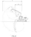
- the first barycenter B 1 of the construction machine depends on the first state in which the bucket 4 is fully loaded at a farthest distance A to the swing axis Z, while the second barycenter B 2 of the construction machine depends on the second state in which the bucket 4 is not loaded at a closest distance G to the swing axis Z.
- the safety range determining section 14b determines whether or not the first barycenter B 1 or the second barycenter B 2 of the construction machine are present in the safety range.
- the signal outputting section 14c provides a closing signal for the safety valves 40 and an alarm signal to the operator when the first barycenter B 1 or the second barycenter B 2 of the construction machine deviate from the safety range.
- the barycenters are XYZ coordinates following the right hand law, which can be calculated and determined as coordinates based on the width axis X, the longitudinal axis Y, and the swing axis Z with respect to the turning joint 11 of the construction machine.
- the safety range should be interpreted as a safe barycentric range, as illustrated in FIG. 5b , in which the construction machine can safely perform excavation work on the ground surface or the surface of a slope in a construction place without rollover or tipping.
- the safety range is set within a critical range defined by a contact surface between the undercarriage 1 and the ground, and has rectangular dimensions including a width W of the contact surface along the axis X and a length L of the contact surface along axis Y
- the critical range includes a surface or a tetrahedron, the barycenter of which deviates from the safety range during the working process.
- a display unit 42 is connected to the controller 14.
- the display unit 42 renders the safety range provided by the signal outputting section 14c of the controller 14 such that the safety range can be visually recognized by the operator. It is preferable that the display unit 42 is disposed in a cab provided in the upper swing structure 6.
- An alarm unit 41 is connected to the controller 14.
- the alarm unit 41 provides aural information to the operator when the first barycenter B 1 or the second barycenter B 2 of the construction machine deviate from the safety range.
- the alarm unit 41 includes a buzzer or a speaker.
- FIG. 4 is a flowchart illustrating a rollover prevention method for a construction machine according to an embodiment of the present disclosure.
- the rollover prevention method includes:
- parameters regarding a change in the angle about the swing axis Z of the turning joint 11 are read from the rotary encoder, and the controller 14 or the barycenter calculating section 14a calculates and calibrates barycentric coordinates.
- parameters regarding a change in the angle about the upper frame width axis X' and the longitudinal axis Y' are read from the 2-axis angle sensor, and the controller 14 or the barycenter calculating section 14a calculates and calibrates barycentric coordinates.
- FIG. 5a and FIG. 5b are schematic views illustrating the barycenters of the undercarriage, the upper frame, and the work attachment of a construction machine.
- the second angle detection unit 13 implemented as the 2-axis angle sensor defines an incline angle ⁇ along the axis X' and an incline angle ⁇ along the axis Y' based on horizontal plane
- the first angle detection unit 12 implemented as the rotary encoder defines a swing angle ⁇ in the axis Z. In the position in which the work attachment 11 faces forwards, the swing angle ⁇ is set to "zero (0).”
- the barycentric coordinates B uc (X uc ,Y uc ,Z uc ) of the undercarriage, the barycentric coordinates B uf (X uf ,Y uf ,Z uf ) of the upper frame, and the barycentric coordinates B at (X at ,Y at ,Z at )of the work attachment are individually calculated and determined as follows:
- the whole weight of the undercarriage (1) is W uc .
- a step of resetting the first angle detection unit 12 is further included.
- the coordinate system OXYZ is built on the bottom plane of undercarriage, therein axis X is always along the width direction of undercarriage, axis Y is always along the longitudinal direction of undercarriage, axis Z is the swing axis.
- the coordinate system OXYZ will move together with the undercarriage, when the swing angle ⁇ is 0°, assume the primal barycenter for the upper frame 1 is B uf0 (X uf0 ,Y uf0 ,Z uf0 ).
- the coordinates of B uf0 (X uf0 ,Y uf0 ,Z uf0 ) can be obtained.
- FIG. 6 is a schematic view illustrating routes drawn by the movement of the bucket illustrated in FIG. 1 .
- the relative barycenter of the work attachment differs depending on the position of the work attachment.
- the work attachment 10 has two extreme states as follows:
- the first state has the most possibility to tip according to the front interface edge between the undercarriage and the slope (hereon, front and back direction is according to the view of driver in the cabin), and the second state has the most possibility to tip according to the back interface edge.
- the barycenter of the first state and the second state is B at1 (X at1 ,Y at1 ,Z at1 ) and B at2 (X at2 ,Y at2 ,Z at2 ) individually.
- the coordinate system OXYZ is built on the bottom plane of undercarriage, therein axis X is always along the width direction of undercarriage, axis Y is always along the longitudinal direction of undercarriage, the coordinate system OXYZ will move together with the undercarriage.
- the coordinate system O'X'Y'Z' is built on the bottom plane of upper frame, therein axis X' is always along the width direction of upper frame, axis Y' is always along the longitudinal direction of upper frame, the coordinate system O'X'Y'Z' will move or rotate together with the upper frame.
- x + By + Cz 0
- Tipping angle “ ⁇ ” equals to the angle between axis X' (parallel to the width direction of upper frame) and the horizontal plane H
- tipping angle “ ⁇ ” equals to the angle between axis Y' (parallel to the longitudinal direction of upper frame) and the horizontal plane H.
- a step of resetting the second angle detection unit 13 is further included.
- the present disclosure includes a step of determining whether or not the first barycenter B 1 of the construction machine or the second barycenter B 2 of the construction machine are present in the safety range, in which the safety range is set within a critical range defined by the contact surface between the undercarriage 1 and the ground.
- the critical range is limited to a rectangular structure having a width W of the contact surface parallel to the axis X and a length L of the contact surface parallel to the axis Y
- the width and length of the safety range depends on a preset critical parameter ⁇ , and are smaller than the width W and the length L of the contact surface.
- the alarm signal is converted and output by the signal outputting section 14c of the controller 14.
- the alarm signal includes an image indicating the risk of rollover or safety state, and is provided to the display unit 42 such that the alarm signal can be visually indicated by the operator.
- the alarm unit outputs an audio signal, the operator can aurally recognize a risk of rollover.
- the present disclosure further includes a step of outputting a closing signal for the safety valves 40 and an alarm signal to the operator when it is determined that the first barycenter B 1 or the second barycenter B 2 of the construction machine deviates from the safety range.
- the controller 14 when it is determined that the barycenter deviates from the threshold value of the safety range in the process of manipulating both a swing operation and a boom-up or boom-down operation, the controller 14, the controller 14 outputs valve closing signals for the safety valves 40a and 40b.
- the supply of working oil discharged from the first hydraulic pump 22 and the second hydraulic pump 23 is stopped, and both the swing operation of the upper frame 5 and the upper swing structure 6 and the boom operation are stopped.
- the present disclosure can be variously applied to construction machines, such as an excavator and a wheel loader.
- the present disclosure provides an operator with safety information while allowing the barycenter to remain in the safety range.
- an alarm is provided to the operator and the supply of working oil is stopped, thereby preventing rollover.
- the safety consciousness of the operator is enhanced, and a rollover is prevented.
Landscapes
- Engineering & Computer Science (AREA)
- Mining & Mineral Resources (AREA)
- Civil Engineering (AREA)
- General Engineering & Computer Science (AREA)
- Structural Engineering (AREA)
- Physics & Mathematics (AREA)
- Acoustics & Sound (AREA)
- Mechanical Engineering (AREA)
- Fluid Mechanics (AREA)
- Component Parts Of Construction Machinery (AREA)
- Operation Control Of Excavators (AREA)
Claims (14)
- Überschlagverhinderungssystem für eine Baumaschine, wobei die Baumaschine ein Arbeitsgerät, wie z.B. einen Ausleger (2), einen Arm (3) oder eine Schaufel (4), mehrere Hydraulikzylinder (28, 33, 35) zum Antreiben des Arbeitsgeräts und einen Schwenkmotor (26) zum Steuern eines Schwenkvorgangs eines oberen Rahmens (5) aufweist, das Überschlagverhinderungssystem umfassend:eine erste Winkelerfassungseinheit (12), die benachbart zu einem Drehgelenk (11) angeordnet ist, um einen Schwenkwinkel des oberen Rahmens zu erfassen, wobei das Drehgelenk an einem zentralen Abschnitt des oberen Rahmens angeordnet ist, der drehbar auf einem Fahrgestell (1) angeordnet ist;eine zweite Winkelerfassungseinheit (13), die am oberen Rahmen angeordnet ist, um eine Winkelbewegung des oberen Rahmens zu erfassen;Sicherheitsventile (40, 40a, 40b), die an Strömungskanälen angeordnet sind, die mit den Hydraulikzylindern für das Arbeitsgerät und den Schwenkmotor in Verbindung stehen, wobei die Sicherheitsventile die den Hydraulikzylindern zugeführten Arbeitsölströme durch Öffnen und Schließen der Strömungskanäle in Reaktion auf externe Signale steuern; undeine elektronische Steuerung (14), die elektrisch mit der ersten Winkelerfassungseinheit, der zweiten Winkelerfassungseinheit und den Sicherheitsventilen verbunden ist, wobei die elektronische Steuerung einen Baryzentrum-Berechnungsabschnitt (14a), einen Sicherheitsbereich-Bestimmungsabschnitt (14b) und einen Signalausgabeabschnitt (14c) umfasst,wobei der Baryzentrum-Berechnungsabschnitt ein Baryzentrum Buc des Fahrgestells, ein Baryzentrum Buf des oberen Rahmens, ein Baryzentrum Bat des Arbeitsgeräts, ein erstes Baryzentrum B1 der Baumaschine in einem ersten Zustand und ein zweites Baryzentrum B2 der Baumaschine in einem zweiten Zustand auf der Grundlage von Werten von Winkeln berechnet, die von der ersten Winkelerfassungseinheit und der zweiten Winkelerfassungseinheit auf der Grundlage eines voreingestellten Algorithmus angelegt werden, wobei das erste Baryzentrum B1 der Baumaschine von dem ersten Zustand abhängt, in dem die Schaufel im weitesten Abstand zur Schwenkachse voll beladen ist, während das zweite Baryzentrum B2 der Baumaschine von dem zweiten Zustand abhängt, in dem die Schaufel im geringsten Abstand G zur Schwenkachse nicht beladen ist, undwobei der Sicherheitsbereich-Bestimmungsabschnitt bestimmt, ob das erste Baryzentrum B1 und das zweite Baryzentrum B2 der Baumaschine in einem Sicherheitsbereich liegen oder nicht,wobei der Signalausgabeabschnitt ein Schließsignal für die Sicherheitsventile und ein Alarmsignal an den Bediener abgibt, wenn das erste Baryzentrum B1 oder das zweite Baryzentrum B2 der Baumaschine vom Sicherheitsbereich abweicht.
- Überschlagverhinderungssystem nach Anspruch 1, ferner mit einer Anzeigeeinheit (42), die mit der Steuerung verbunden ist, wobei die Anzeigeeinheit den von dem Signalausgabeabschnitt der Steuerung bereitgestellten Sicherheitsbereich ausgibt, so dass der Sicherheitsbereich für den Bediener visuell erkennbar ist.
- Überschlagverhinderungssystem nach Anspruch 1, ferner umfassend eine Alarmeinheit (41), die mit der Steuerung verbunden ist, wobei die Alarmeinheit dem Bediener akustische Informationen liefert, wenn das erste Baryzentrum B1 oder das zweite Baryzentrum B2 der Baumaschine vom Sicherheitsbereich abweicht.
- Überschlagverhinderungssystem nach Anspruch 1, wobei die Sicherheitsventile ein erstes Sicherheitsventil (40a) umfassen, das an einem der Strömungskanäle angeordnet ist, um einen von der ersten Hydraulikpumpe zugeführten Ölstrom zu blockieren, und ein zweites Sicherheitsventil (40b), das an dem anderen der Strömungskanäle angeordnet ist, um einen von der zweiten Hydraulikpumpe zugeführten Ölstrom zu blockieren.
- Überschlagverhinderungssystem nach Anspruch 1, wobei die Sicherheitsventile an Steuersignalleitungen (Pi) angeordnet sind, die sich von der Steuervorrichtung zu Schiebern von hydraulischen Steuerventilen erstrecken.
- Überschlagverhinderungssystem nach Anspruch 1, wobei die zweite Winkelerfassungseinheit eine System-on-Chip-Vorrichtung umfasst, die auf der elektronischen Steuerung angeordnet ist.
- Überschlagverhinderungssystem nach Anspruch 4, wobei jedes der Sicherheitsventile ein Magnetventil umfasst.
- Überschlagverhinderungssystem nach Anspruch 5, wobei jedes der Sicherheitsventile ein Magnetventil umfasst.
- Verfahren zur Überschlagverhinderung einer Baumaschine mit einem Überschlagverhinderungssystem nach einem der Ansprüche 1 bis 8, umfassendErfassen einer Änderung eines Schwenkwinkels des oberen Rahmens (5) der Baumaschine um die Schwenkachse Z in Bezug auf das Drehgelenk (11) unter Verwendung der ersten Winkelerfassungseinheit (12), die neben dem Drehgelenk angeordnet ist;Erfassen einer Winkelbewegung des oberen Rahmens entlang der Breitenachse X' und der Längsachse Y' der Baumaschine unter Verwendung der zweiten Winkelerfassungseinheit (13), die neben dem oberen Rahmen angeordnet ist;Berechnen von baryzentrischen Koordinaten Buf(Xuf, Yuf, Zuf) des oberen Rahmens, definiert in Bezug auf die Breitenachse X, die Längsachse Y und die Schwenkachse Z;Berechnen eines ersten Baryzentrums Bat1(Xat1, Yat1, Zat1) des Arbeitsgeräts in einem ersten Zustand, in dem die Schaufel (4) im weitesten Abstand zur Schwenkachse Z voll beladen ist, und eines zweiten Baryzentrums Wat1 des Arbeitsgeräts in einem zweiten Zustand, in dem die Schaufel im geringsten Abstand zur Schwenkachse Z nicht beladen ist, auf der Grundlage eines im ersten Zustand ermittelten ersten Gewichts des Arbeitsgeräts und eines im zweiten Zustand ermittelten zweiten Gewichts Wat2 des Arbeitsgeräts;Berechnen eines ersten Baryzentrums B1(X1,Y1,Z1) der Baumaschine im ersten Zustand und eines zweiten Baryzentrums B2(X2, Y2, Z2) der Baumaschine im zweiten Zustand, auf der Grundlage der baryzentrischen Koordinaten Buc(Xuc, Yuc, Zuc) des Fahrgestells, dem Gewicht W uc des Fahrgestells, dem Gewicht W uf des oberen Rahmens, dem Gewicht Wat1 des Arbeitsgeräts im ersten Zustand und dem Gewicht Wat2 des Arbeitsgeräts im zweiten Zustand,wobei Xuf, Yuf, Zuf, Xat1, Yat1, Zat1, Xuc, Yuc, Zuc, Wuc, B1, and B2 durch die folgenden Formeln definiert sind:





 das Verfahren zur Überschlagverhinderung ferner umfassend:Bestimmen, ob das erste Baryzentrum B1 der Baumaschine und das zweite Baryzentrum B2 der Baumaschine in einem Sicherheitsbereich liegen oder nicht; undAusgeben eines Schließsignals für die Sicherheitsventile und eines Alarmsignals an den Bediener, wenn das erste Baryzentrum B1 oder das zweite Baryzentrum B2 der Baumaschine vom Sicherheitsbereich abweicht.
 - Verfahren zur Überschlagverhinderung nach Anspruch 9, wobei der Sicherheitsbereich innerhalb eines kritischen Bereichs festgelegt wird, der durch eine Kontaktfläche zwischen dem Fahrgestell und dem Boden definiert ist, wobei der kritische Bereich auf eine rechteckige Struktur mit einer Breite W der Kontaktfläche entlang der Achse X und einer Länge L der Kontaktfläche entlang der Achse Y begrenzt ist.
- Verfahren zur Überschlagverhinderung nach Anspruch 9, ferner umfassend Zurücksetzen der ersten Winkelerfassungseinheit, um die Änderung des Schwenkwinkels des oberen Rahmens um die Schwenkachse Z in Bezug auf das Drehgelenk zu erfassen.
- Verfahren zur Überschlagverhinderung nach Anspruch 11, ferner umfassend das Zurücksetzen der zweiten Winkelerfassungseinheit, um die Winkelbewegung der oberen Schwenkstruktur oder des oberen Rahmens entlang der Breitenachse X' und der Längsachse Y' der Baumaschine zu erfassen.
- Verfahren zur Überschlagverhinderung nach Anspruch 9, wobei die erste Winkelerfassungseinheit einen Drehgeber und die zweite Winkelerfassungseinheit einen 2-Achsen-Winkelsensor umfasst.
- Verfahren zur Überschlagverhinderung nach Anspruch 9, wobei der 2-Achsen-Winkelsensor einen Neigungswinkel α entlang der Achse X' und einen Neigungswinkel β entlang der Achse Y'definiert, während der Drehgeber einen Schwenkwinkel θ in der Achse Z definiert, und
wobei in einer Position, in der das Arbeitsgerät nach vorne zeigt, der Schwenkwinkel θ auf 0 eingestellt ist.
Applications Claiming Priority (1)
| Application Number | Priority Date | Filing Date | Title |
|---|---|---|---|
| PCT/CN2016/098499 WO2018045542A1 (en) | 2016-09-09 | 2016-09-09 | Rollover prevention system and method for construction machine |
Publications (4)
| Publication Number | Publication Date |
|---|---|
| EP3510202A1 EP3510202A1 (de) | 2019-07-17 |
| EP3510202A4 EP3510202A4 (de) | 2020-06-24 |
| EP3510202B1 true EP3510202B1 (de) | 2023-08-16 |
| EP3510202C0 EP3510202C0 (de) | 2023-08-16 |
Family
ID=61561635
Family Applications (1)
| Application Number | Title | Priority Date | Filing Date |
|---|---|---|---|
| EP16915477.0A Active EP3510202B1 (de) | 2016-09-09 | 2016-09-09 | Überschlagverhinderungssystem und verfahren für eine baumaschine |
Country Status (4)
| Country | Link |
|---|---|
| US (1) | US11015320B2 (de) |
| EP (1) | EP3510202B1 (de) |
| CN (1) | CN110799711A (de) |
| WO (1) | WO2018045542A1 (de) |
Families Citing this family (8)
| Publication number | Priority date | Publication date | Assignee | Title |
|---|---|---|---|---|
| CN110945189A (zh) * | 2017-09-07 | 2020-03-31 | 住友建机株式会社 | 挖土机 |
| US10988188B2 (en) * | 2018-12-12 | 2021-04-27 | Continental Automotive Systems, Inc. | Overturn control by side support |
| JP7264796B2 (ja) * | 2019-11-21 | 2023-04-25 | 株式会社小松製作所 | 転倒リスク提示装置および転倒リスク提示方法 |
| JP2022013134A (ja) * | 2020-07-03 | 2022-01-18 | キャタピラー エス エー アール エル | 履帯車両の自律走行制御方法、履帯車両のコントローラおよび履帯車両 |
| IT202000019597A1 (it) * | 2020-08-07 | 2022-02-07 | Soilmec Spa | Macchina per l’esecuzione di scavi, in particolare per la perforazione, e metodo associato a tale macchina. |
| JP7706901B2 (ja) | 2021-03-08 | 2025-07-14 | 株式会社小松製作所 | 転倒評価システム、転倒評価方法及び作業機械 |
| CN112942481B (zh) * | 2021-04-29 | 2022-10-04 | 三一重机有限公司 | 一种挖掘机及其防倾翻控制方法、装置及存储介质 |
| JP7740909B2 (ja) * | 2021-06-14 | 2025-09-17 | ヤンマーホールディングス株式会社 | 作業機械及び作業機械の制御方法 |
Family Cites Families (21)
| Publication number | Priority date | Publication date | Assignee | Title |
|---|---|---|---|---|
| CN2056165U (zh) * | 1989-03-15 | 1990-04-18 | 王秀亮 | 装在叉车上的铲斗装置 |
| JPH07207711A (ja) | 1994-01-11 | 1995-08-08 | Yutani Heavy Ind Ltd | 建設機械の転倒防止装置 |
| JP3845597B2 (ja) * | 2002-05-01 | 2006-11-15 | 日立建機株式会社 | 建設機械の異常検出装置 |
| JP5148266B2 (ja) * | 2005-01-31 | 2013-02-20 | 株式会社小松製作所 | チルトフロアを備えた作業車両 |
| CN201025755Y (zh) * | 2006-10-11 | 2008-02-27 | 陈兴 | 耕滚机 |
| CN201240266Y (zh) * | 2008-06-07 | 2009-05-20 | 武小玉 | 拖拉机轮轴调节机构 |
| JP2010127363A (ja) | 2008-11-27 | 2010-06-10 | Nachi Fujikoshi Corp | 油圧駆動装置 |
| EP2233354A1 (de) * | 2009-03-26 | 2010-09-29 | Officine Cusini S.r.L. | Säule für die Pendelrückwand von Kipplastern |
| US8768581B2 (en) * | 2010-05-24 | 2014-07-01 | Hitachi Construction Machinery Co., Ltd. | Work machine safety device |
| US8935048B2 (en) * | 2011-03-24 | 2015-01-13 | Yuliang Sun | Multi-function vehicle-rollover judgment system and automatic anti-rollover device |
| DE112012003346B4 (de) * | 2011-06-10 | 2017-01-05 | Hitachi Construction Machinery Co., Ltd. | Arbeitsmaschine |
| CN202347549U (zh) | 2011-10-31 | 2012-07-25 | 中联重科股份有限公司 | 挖掘机的工作姿态的测量单元、防倾翻装置和挖掘机 |
| JP2013189767A (ja) * | 2012-03-13 | 2013-09-26 | Sumitomo Heavy Ind Ltd | 電動式旋回装置 |
| CN102767208B (zh) * | 2012-08-09 | 2014-08-27 | 厦门大学 | 一种轮式装载机侧倾翻预测的方法 |
| WO2014167732A1 (ja) * | 2013-04-12 | 2014-10-16 | 株式会社小松製作所 | 油圧シリンダのストローク動作校正制御装置及び油圧シリンダのストローク動作校正制御方法 |
| CN203373804U (zh) | 2013-05-31 | 2014-01-01 | 徐州徐工挖掘机械有限公司 | 挖掘机防倾翻保护系统 |
| ITPI20130076A1 (it) * | 2013-08-28 | 2015-03-01 | Pasquale Villa | Dispositivo antiribaltamento per veicoli |
| CN103518478A (zh) * | 2013-10-21 | 2014-01-22 | 山东常林农业装备股份有限公司 | 一种收获机械用双滑杆式升高卸粮机构 |
| CN104018529A (zh) * | 2014-05-20 | 2014-09-03 | 山重建机有限公司 | 一种挖掘机配重装置及其布置方法 |
| PT3169540T (pt) * | 2014-07-18 | 2018-08-01 | Piaggio & C Spa | Veículo com três ou mais rodas provido de um sistema estabilizador anti-rolamento e processo de controlo antirolamento de um veículo tendo pelo menos três rodas |
| JP6297468B2 (ja) * | 2014-10-28 | 2018-03-20 | 住友建機株式会社 | ショベル |
-
2016
- 2016-09-09 EP EP16915477.0A patent/EP3510202B1/de active Active
- 2016-09-09 CN CN201680089111.1A patent/CN110799711A/zh active Pending
- 2016-09-09 WO PCT/CN2016/098499 patent/WO2018045542A1/en not_active Ceased
- 2016-09-09 US US16/331,659 patent/US11015320B2/en not_active Expired - Fee Related
Also Published As
| Publication number | Publication date |
|---|---|
| WO2018045542A1 (en) | 2018-03-15 |
| US20190234048A1 (en) | 2019-08-01 |
| EP3510202C0 (de) | 2023-08-16 |
| CN110799711A (zh) | 2020-02-14 |
| US11015320B2 (en) | 2021-05-25 |
| EP3510202A4 (de) | 2020-06-24 |
| EP3510202A1 (de) | 2019-07-17 |
Similar Documents
| Publication | Publication Date | Title |
|---|---|---|
| US11015320B2 (en) | Rollover prevention system and method for construction machine | |
| EP3399109B1 (de) | Bagger | |
| KR101729050B1 (ko) | 건설 기계의 제어 시스템 및 제어 방법 | |
| JP7289232B2 (ja) | 作業機械および作業機械の制御システム | |
| KR101812127B1 (ko) | 작업 차량의 제어 시스템, 제어 방법, 및 작업 차량 | |
| KR101859263B1 (ko) | 작업 기계의 제어 시스템 및 작업 기계의 제어 방법 | |
| KR101989332B1 (ko) | 작업 기계의 표시 시스템 및 작업 기계 | |
| CN105008623B (zh) | 建筑机械的控制系统、建筑机械及建筑机械的控制方法 | |
| EP3572590B1 (de) | Arbeitsmaschine | |
| CN112513378B (zh) | 作业机械 | |
| US8509999B2 (en) | Abnormal operation detection device | |
| KR102402518B1 (ko) | 작업 기계 | |
| KR102580139B1 (ko) | 유압 셔블 | |
| CN109689978B (zh) | 作业机械 | |
| CN113924396B (zh) | 作业机械及作业机械的控制方法 | |
| CN107306500A (zh) | 作业机械的控制装置、作业机械以及作业机械的控制方法 | |
| EP4012116A1 (de) | Baumaschine | |
| KR20220003042A (ko) | 작업 기계 | |
| KR102378264B1 (ko) | 작업 기계 | |
| EP4421247B1 (de) | Antriebsvorrichtung für baumaschine und baumaschinensystem damit | |
| CN106715803A (zh) | 挖土机 | |
| WO2018189765A1 (ja) | 建設機械および制御方法 | |
| JP7510378B2 (ja) | 建設機械 | |
| KR20230033461A (ko) | 건설기계 | |
| KR102378805B1 (ko) | 건설 기계 |
Legal Events
| Date | Code | Title | Description |
|---|---|---|---|
| STAA | Information on the status of an ep patent application or granted ep patent |
Free format text: STATUS: THE INTERNATIONAL PUBLICATION HAS BEEN MADE |
|
| PUAI | Public reference made under article 153(3) epc to a published international application that has entered the european phase |
Free format text: ORIGINAL CODE: 0009012 |
|
| STAA | Information on the status of an ep patent application or granted ep patent |
Free format text: STATUS: REQUEST FOR EXAMINATION WAS MADE |
|
| 17P | Request for examination filed |
Effective date: 20190405 |
|
| AK | Designated contracting states |
Kind code of ref document: A1 Designated state(s): AL AT BE BG CH CY CZ DE DK EE ES FI FR GB GR HR HU IE IS IT LI LT LU LV MC MK MT NL NO PL PT RO RS SE SI SK SM TR |
|
| AX | Request for extension of the european patent |
Extension state: BA ME |
|
| DAV | Request for validation of the european patent (deleted) | ||
| DAX | Request for extension of the european patent (deleted) | ||
| A4 | Supplementary search report drawn up and despatched |
Effective date: 20200526 |
|
| RIC1 | Information provided on ipc code assigned before grant |
Ipc: E02F 9/22 20060101ALI20200518BHEP Ipc: E02F 9/26 20060101ALI20200518BHEP Ipc: E02F 9/20 20060101ALI20200518BHEP Ipc: E02F 9/24 20060101AFI20200518BHEP |
|
| GRAP | Despatch of communication of intention to grant a patent |
Free format text: ORIGINAL CODE: EPIDOSNIGR1 |
|
| STAA | Information on the status of an ep patent application or granted ep patent |
Free format text: STATUS: GRANT OF PATENT IS INTENDED |
|
| INTG | Intention to grant announced |
Effective date: 20230315 |
|
| GRAS | Grant fee paid |
Free format text: ORIGINAL CODE: EPIDOSNIGR3 |
|
| GRAA | (expected) grant |
Free format text: ORIGINAL CODE: 0009210 |
|
| STAA | Information on the status of an ep patent application or granted ep patent |
Free format text: STATUS: THE PATENT HAS BEEN GRANTED |
|
| AK | Designated contracting states |
Kind code of ref document: B1 Designated state(s): AL AT BE BG CH CY CZ DE DK EE ES FI FR GB GR HR HU IE IS IT LI LT LU LV MC MK MT NL NO PL PT RO RS SE SI SK SM TR |
|
| REG | Reference to a national code |
Ref country code: GB Ref legal event code: FG4D |
|
| REG | Reference to a national code |
Ref country code: CH Ref legal event code: EP Ref country code: DE Ref legal event code: R096 Ref document number: 602016082045 Country of ref document: DE |
|
| REG | Reference to a national code |
Ref country code: IE Ref legal event code: FG4D |
|
| U01 | Request for unitary effect filed |
Effective date: 20230912 |
|
| U07 | Unitary effect registered |
Designated state(s): AT BE BG DE DK EE FI FR IT LT LU LV MT NL PT SE SI Effective date: 20231004 |
|
| U20 | Renewal fee for the european patent with unitary effect paid |
Year of fee payment: 8 Effective date: 20231005 |
|
| PG25 | Lapsed in a contracting state [announced via postgrant information from national office to epo] |
Ref country code: GR Free format text: LAPSE BECAUSE OF FAILURE TO SUBMIT A TRANSLATION OF THE DESCRIPTION OR TO PAY THE FEE WITHIN THE PRESCRIBED TIME-LIMIT Effective date: 20231117 |
|
| PG25 | Lapsed in a contracting state [announced via postgrant information from national office to epo] |
Ref country code: IS Free format text: LAPSE BECAUSE OF FAILURE TO SUBMIT A TRANSLATION OF THE DESCRIPTION OR TO PAY THE FEE WITHIN THE PRESCRIBED TIME-LIMIT Effective date: 20231216 |
|
| PG25 | Lapsed in a contracting state [announced via postgrant information from national office to epo] |
Ref country code: RS Free format text: LAPSE BECAUSE OF FAILURE TO SUBMIT A TRANSLATION OF THE DESCRIPTION OR TO PAY THE FEE WITHIN THE PRESCRIBED TIME-LIMIT Effective date: 20230816 Ref country code: NO Free format text: LAPSE BECAUSE OF FAILURE TO SUBMIT A TRANSLATION OF THE DESCRIPTION OR TO PAY THE FEE WITHIN THE PRESCRIBED TIME-LIMIT Effective date: 20231116 Ref country code: IS Free format text: LAPSE BECAUSE OF FAILURE TO SUBMIT A TRANSLATION OF THE DESCRIPTION OR TO PAY THE FEE WITHIN THE PRESCRIBED TIME-LIMIT Effective date: 20231216 Ref country code: HR Free format text: LAPSE BECAUSE OF FAILURE TO SUBMIT A TRANSLATION OF THE DESCRIPTION OR TO PAY THE FEE WITHIN THE PRESCRIBED TIME-LIMIT Effective date: 20230816 Ref country code: GR Free format text: LAPSE BECAUSE OF FAILURE TO SUBMIT A TRANSLATION OF THE DESCRIPTION OR TO PAY THE FEE WITHIN THE PRESCRIBED TIME-LIMIT Effective date: 20231117 |
|
| PG25 | Lapsed in a contracting state [announced via postgrant information from national office to epo] |
Ref country code: PL Free format text: LAPSE BECAUSE OF FAILURE TO SUBMIT A TRANSLATION OF THE DESCRIPTION OR TO PAY THE FEE WITHIN THE PRESCRIBED TIME-LIMIT Effective date: 20230816 |
|
| PG25 | Lapsed in a contracting state [announced via postgrant information from national office to epo] |
Ref country code: ES Free format text: LAPSE BECAUSE OF FAILURE TO SUBMIT A TRANSLATION OF THE DESCRIPTION OR TO PAY THE FEE WITHIN THE PRESCRIBED TIME-LIMIT Effective date: 20230816 |
|
| PG25 | Lapsed in a contracting state [announced via postgrant information from national office to epo] |
Ref country code: SM Free format text: LAPSE BECAUSE OF FAILURE TO SUBMIT A TRANSLATION OF THE DESCRIPTION OR TO PAY THE FEE WITHIN THE PRESCRIBED TIME-LIMIT Effective date: 20230816 Ref country code: RO Free format text: LAPSE BECAUSE OF FAILURE TO SUBMIT A TRANSLATION OF THE DESCRIPTION OR TO PAY THE FEE WITHIN THE PRESCRIBED TIME-LIMIT Effective date: 20230816 Ref country code: ES Free format text: LAPSE BECAUSE OF FAILURE TO SUBMIT A TRANSLATION OF THE DESCRIPTION OR TO PAY THE FEE WITHIN THE PRESCRIBED TIME-LIMIT Effective date: 20230816 Ref country code: CZ Free format text: LAPSE BECAUSE OF FAILURE TO SUBMIT A TRANSLATION OF THE DESCRIPTION OR TO PAY THE FEE WITHIN THE PRESCRIBED TIME-LIMIT Effective date: 20230816 Ref country code: SK Free format text: LAPSE BECAUSE OF FAILURE TO SUBMIT A TRANSLATION OF THE DESCRIPTION OR TO PAY THE FEE WITHIN THE PRESCRIBED TIME-LIMIT Effective date: 20230816 |
|
| REG | Reference to a national code |
Ref country code: CH Ref legal event code: PL |
|
| REG | Reference to a national code |
Ref country code: DE Ref legal event code: R097 Ref document number: 602016082045 Country of ref document: DE |
|
| PG25 | Lapsed in a contracting state [announced via postgrant information from national office to epo] |
Ref country code: MC Free format text: LAPSE BECAUSE OF FAILURE TO SUBMIT A TRANSLATION OF THE DESCRIPTION OR TO PAY THE FEE WITHIN THE PRESCRIBED TIME-LIMIT Effective date: 20230816 |
|
| PLBE | No opposition filed within time limit |
Free format text: ORIGINAL CODE: 0009261 |
|
| STAA | Information on the status of an ep patent application or granted ep patent |
Free format text: STATUS: NO OPPOSITION FILED WITHIN TIME LIMIT |
|
| REG | Reference to a national code |
Ref country code: IE Ref legal event code: MM4A |
|
| PG25 | Lapsed in a contracting state [announced via postgrant information from national office to epo] |
Ref country code: IE Free format text: LAPSE BECAUSE OF NON-PAYMENT OF DUE FEES Effective date: 20230909 |
|
| PG25 | Lapsed in a contracting state [announced via postgrant information from national office to epo] |
Ref country code: CH Free format text: LAPSE BECAUSE OF NON-PAYMENT OF DUE FEES Effective date: 20230930 |
|
| 26N | No opposition filed |
Effective date: 20240517 |
|
| GBPC | Gb: european patent ceased through non-payment of renewal fee |
Effective date: 20231116 |
|
| PG25 | Lapsed in a contracting state [announced via postgrant information from national office to epo] |
Ref country code: IE Free format text: LAPSE BECAUSE OF NON-PAYMENT OF DUE FEES Effective date: 20230909 Ref country code: CH Free format text: LAPSE BECAUSE OF NON-PAYMENT OF DUE FEES Effective date: 20230930 |
|
| PG25 | Lapsed in a contracting state [announced via postgrant information from national office to epo] |
Ref country code: GB Free format text: LAPSE BECAUSE OF NON-PAYMENT OF DUE FEES Effective date: 20231116 |
|
| U20 | Renewal fee for the european patent with unitary effect paid |
Year of fee payment: 9 Effective date: 20240926 |
|
| PG25 | Lapsed in a contracting state [announced via postgrant information from national office to epo] |
Ref country code: GB Free format text: LAPSE BECAUSE OF NON-PAYMENT OF DUE FEES Effective date: 20231116 |
|
| PG25 | Lapsed in a contracting state [announced via postgrant information from national office to epo] |
Ref country code: CY Free format text: LAPSE BECAUSE OF FAILURE TO SUBMIT A TRANSLATION OF THE DESCRIPTION OR TO PAY THE FEE WITHIN THE PRESCRIBED TIME-LIMIT; INVALID AB INITIO Effective date: 20160909 |
|
| PG25 | Lapsed in a contracting state [announced via postgrant information from national office to epo] |
Ref country code: HU Free format text: LAPSE BECAUSE OF FAILURE TO SUBMIT A TRANSLATION OF THE DESCRIPTION OR TO PAY THE FEE WITHIN THE PRESCRIBED TIME-LIMIT; INVALID AB INITIO Effective date: 20160909 |
|
| PG25 | Lapsed in a contracting state [announced via postgrant information from national office to epo] |
Ref country code: TR Free format text: LAPSE BECAUSE OF FAILURE TO SUBMIT A TRANSLATION OF THE DESCRIPTION OR TO PAY THE FEE WITHIN THE PRESCRIBED TIME-LIMIT Effective date: 20230816 |
|
| U90 | Renewal fees not paid: noting of loss of rights |
Free format text: RENEWAL FEE NOT PAID FOR YEAR 10 Effective date: 20260416 |