EP3510462B1 - Système et procédé pour conduire un véhicule - Google Patents
Système et procédé pour conduire un véhicule Download PDFInfo
- Publication number
- EP3510462B1 EP3510462B1 EP17740623.8A EP17740623A EP3510462B1 EP 3510462 B1 EP3510462 B1 EP 3510462B1 EP 17740623 A EP17740623 A EP 17740623A EP 3510462 B1 EP3510462 B1 EP 3510462B1
- Authority
- EP
- European Patent Office
- Prior art keywords
- vehicle
- sensors
- sensor
- travel
- sensor group
- Prior art date
- Legal status (The legal status is an assumption and is not a legal conclusion. Google has not performed a legal analysis and makes no representation as to the accuracy of the status listed.)
- Active
Links
Images



Classifications
-
- G—PHYSICS
- G05—CONTROLLING; REGULATING
- G05D—SYSTEMS FOR CONTROLLING OR REGULATING NON-ELECTRIC VARIABLES
- G05D1/00—Control of position, course, altitude or attitude of land, water, air or space vehicles, e.g. using automatic pilots
- G05D1/02—Control of position or course in two dimensions
- G05D1/021—Control of position or course in two dimensions specially adapted to land vehicles
- G05D1/0257—Control of position or course in two dimensions specially adapted to land vehicles using a radar
-
- G—PHYSICS
- G05—CONTROLLING; REGULATING
- G05D—SYSTEMS FOR CONTROLLING OR REGULATING NON-ELECTRIC VARIABLES
- G05D1/00—Control of position, course, altitude or attitude of land, water, air or space vehicles, e.g. using automatic pilots
- G05D1/02—Control of position or course in two dimensions
- G05D1/021—Control of position or course in two dimensions specially adapted to land vehicles
- G05D1/0259—Control of position or course in two dimensions specially adapted to land vehicles using magnetic or electromagnetic means
- G05D1/0265—Control of position or course in two dimensions specially adapted to land vehicles using magnetic or electromagnetic means using buried wires
-
- B—PERFORMING OPERATIONS; TRANSPORTING
- B60—VEHICLES IN GENERAL
- B60W—CONJOINT CONTROL OF VEHICLE SUB-UNITS OF DIFFERENT TYPE OR DIFFERENT FUNCTION; CONTROL SYSTEMS SPECIALLY ADAPTED FOR HYBRID VEHICLES; ROAD VEHICLE DRIVE CONTROL SYSTEMS FOR PURPOSES NOT RELATED TO THE CONTROL OF A PARTICULAR SUB-UNIT
- B60W40/00—Estimation or calculation of non-directly measurable driving parameters for road vehicle drive control systems not related to the control of a particular sub unit, e.g. by using mathematical models
- B60W40/10—Estimation or calculation of non-directly measurable driving parameters for road vehicle drive control systems not related to the control of a particular sub unit, e.g. by using mathematical models related to vehicle motion
-
- G—PHYSICS
- G05—CONTROLLING; REGULATING
- G05D—SYSTEMS FOR CONTROLLING OR REGULATING NON-ELECTRIC VARIABLES
- G05D1/00—Control of position, course, altitude or attitude of land, water, air or space vehicles, e.g. using automatic pilots
- G05D1/02—Control of position or course in two dimensions
- G05D1/021—Control of position or course in two dimensions specially adapted to land vehicles
- G05D1/0268—Control of position or course in two dimensions specially adapted to land vehicles using internal positioning means
- G05D1/0272—Control of position or course in two dimensions specially adapted to land vehicles using internal positioning means comprising means for registering the travel distance, e.g. revolutions of wheels
-
- B—PERFORMING OPERATIONS; TRANSPORTING
- B60—VEHICLES IN GENERAL
- B60W—CONJOINT CONTROL OF VEHICLE SUB-UNITS OF DIFFERENT TYPE OR DIFFERENT FUNCTION; CONTROL SYSTEMS SPECIALLY ADAPTED FOR HYBRID VEHICLES; ROAD VEHICLE DRIVE CONTROL SYSTEMS FOR PURPOSES NOT RELATED TO THE CONTROL OF A PARTICULAR SUB-UNIT
- B60W2520/00—Input parameters relating to overall vehicle dynamics
- B60W2520/06—Direction of travel
Definitions
- the invention relates to a system and a method for operating a vehicle.
- the invention is therefore based on the object of developing a system for determining the direction of travel of a vehicle, with the aim of improving environmental protection.
- the object is achieved in the system for determining the direction of travel of a vehicle according to the features specified in claim 8 and in the method according to the features specified in claim 1.
- this determination is only made if the sensors also detect the reinforcing rod, that is to say cross it, and thus generate corresponding signals. Otherwise, the direction of travel is considered to be parallel to the reinforcement rod or a specified direction angle value is assigned to it.
- the advantage here is that the direction of travel of the vehicle can be determined relative to the reinforcing rod.
- the concrete floor of a roadway in particular a factory hall, usually has reinforcing bars.
- the vehicle needs to be equipped with sensors and an evaluation means for evaluating the signals from the reinforcing rod.
- the determination of the direction of travel can therefore be carried out with little material expenditure.
- Environmental protection is improved.
- ⁇ 1 arctan v ⁇ t ⁇ 1 ⁇ 1
- the vehicle has a second sensor group, the second sensor group having at least two sensors which are arranged along a second reference line at a distance a 2 from one another, the first sensor group and the second sensor group being arranged such that the The first reference line and the second reference line are arranged parallel to one another and are spaced apart from one another by the distance x, a first sensor of the second sensor group detecting the reinforcing rod at a third point in time t 3 after the second point in time t 2 , with a second sensor of the second sensor group the reinforcing rod at a fourth point in time t 4 , in particular after the third point in time t 3 , the time difference t ⁇ 2 being determined between the third point in time t 3 and the fourth point in time t 4 , the time difference t ⁇ 2 , the speed v and the distance a 2 determine an angle ⁇ 2 mt, which indicates the angle between the direction of travel of the vehicle and the direction of extension of the reinforcing rod at the third
- ⁇ 2 arctan v ⁇ t ⁇ 2 ⁇ 2
- the advantage here is that a detection signal that was recorded by means of a sensor of the second sensor group can be easily assigned to the detection signal that was recorded by a sensor of the first sensor group by dividing the time between the two signals with the time interval ⁇ t is compared.
- the advantage here is that the speed of the vehicle can be determined redundantly by means of the speed sensor and the sensor. Thus, the measurement accuracy is improved.
- the speed sensor can advantageously be dispensed with. Thus, environmental protection is improved.
- the system comprises the vehicle and a concrete floor having at least one reinforcement bar, wherein the vehicle is movably arranged on the concrete floor, wherein the vehicle has an evaluation means and a first sensor group having at least two sensors, wherein the sensors are arranged at a distance from one another along a first reference line, where the sensors are set up to detect the reinforcement bar, wherein the evaluation means is connected to the sensors and is set up to determine the direction of travel from the signals from the sensors.
- the advantage here is that the direction of travel of the vehicle can be determined relative to the reinforcing rod.
- the concrete floor of a roadway, in particular a factory hall usually has reinforcing bars.
- the determination of the direction of travel can therefore be carried out with little material expenditure. Environmental protection is improved.
- the vehicle has a second sensor group, having at least two sensors, the sensors of the second sensor group being arranged along a second reference line at a distance from one another, the first reference line and the second reference line being arranged at a distance from one another and parallel to one another, wherein the sensors of the second sensor group are set up to detect the reinforcement bar, the evaluation means being connected to the sensors of the second sensor group and being set up to determine the direction of travel from the signals from the sensors of the second sensor group.
- the sensors are arranged on a vehicle floor of the vehicle.
- the advantage here is that the distance between the vehicle and the concrete floor is smaller than when the sensor is arranged at other positions on the vehicle. A good signal-to-noise ratio can thus be achieved when determining the signal from the reinforcement rod.
- only air is arranged between the sensor and the concrete floor.
- the sensors are radar sensors and / or inductive sensors which are set up to determine the thickness and / or the density and / or the depth of the reinforcement bar in the concrete floor.
- the advantage here is that a characteristic reference profile of the reinforcement along a route can be determined by means of the sensor.
- the vehicle has a vehicle controller, in particular the vehicle being designed as a driverless transport vehicle, the vehicle controller being connected to the evaluation means.
- vehicle controller in particular the vehicle being designed as a driverless transport vehicle, the vehicle controller being connected to the evaluation means.
- the evaluation means has a computing unit which is set up to calculate trigonometric functions.
- the evaluation means has a time measuring means which is set up to determine the time between two successive points in time when the reinforcing rod is detected.
- the system has a speed sensor for determining the speed v of the vehicle in the direction of travel.
- the advantage here is that speed deviations can be detected in a simple manner.
- the concrete floor has a large number of reinforcing bars.
- the advantage here is that the direction of travel of the vehicle can be determined by means of the reinforcing bars at different positions on the concrete floor.
- the reinforcing bars can advantageously be arranged distributed in the concrete floor in such a way that the vehicle detects a reinforcing bar with a sensor of the first sensor group and / or a sensor of the second sensor group at any time.
- the time interval ⁇ t is calculated which elapses between the point in time at which a sensor of the first sensor group detects a reinforcement bar and the point in time at which a sensor of the second sensor group detects the same reinforcement bar.
- the reinforcing bars are arranged parallel to one another and / or as a grid.
- the advantage here is that two sensors are sufficient for each sensor group to determine the direction of travel of the vehicle.
- each sensor group has a multiplicity of sensors, the evaluation means being set up to evaluate the signals from the sensors of the first and second sensor groups.
- the advantage here is that the measurement accuracy is improved.
- the angle to the reinforcement bar can be calculated by means of different sensor pairs of a sensor group and a mean value of the angles can be determined. Thus, the measurement accuracy is improved.
- the evaluation means is set up to select individual sensors from a sensor group for determining the direction of travel of the vehicle.
- the advantage here is that a sensor which permanently receives the signal from a reinforcing rod crossing the reinforcing rod can be ignored by the evaluation means. Thus, the measurement accuracy is improved.
- Vehicle 1 shown has a first and a second sensor group for detecting the reinforcement in the concrete floor, each sensor group at least two
- Sensors (2.1, 2.2, 3.1, 3.2) which are arranged along a respective reference line 6 at a distance from one another.
- the sensors (2.1, 2.2, 3.1, 3.2) are arranged on the vehicle 1 in such a way that the reference lines of the first and second sensor groups are each arranged in parallel.
- the sensor groups are arranged at a distance x from one another.
- the sensors (2.1, 2.2, 3.1, 3.2) are preferably designed as inductive sensors and / or radar sensors.
- the sensors (2.1, 2.2, 3.1, 3.2) are preferably arranged on the vehicle floor of the vehicle 1 and oriented towards the concrete floor.
- the reference lines of the first and second sensor groups are each arranged transversely to the direction of travel 9 of the vehicle 1.
- the vehicle 1 has an evaluation means 4, the evaluation means 4 being connected to the sensors (2.1, 2.2, 3.1, 3.2) of the sensor groups, in particular by means of a connection means 5.
- the evaluation means 4 is used to evaluate the signals from the sensors (2.1, 2.2, 3.1, 3.2).
- the evaluation means 4 preferably has a computing unit which is set up to calculate trigonometric functions.
- the vehicle 1 has a speed sensor, the evaluation means 4 being connected to the speed sensor.
- the evaluation means 4 is set up to evaluate the signals from the speed sensor.
- the system according to the invention for determining the direction of travel of a vehicle has the vehicle 1 and the concrete floor, the vehicle 1 being movable on the concrete floor.
- the concrete floor has the reinforcement for reinforcing the concrete floor.
- the reinforcement is metallic and has a greater ductility than concrete.
- the reinforcement is preferably made of steel, in particular reinforcing steel. Reinforcing bars and / or welded wire meshes and / or reinforcing steel in rings and / or reinforcing wire and / or lattice girders can be used.
- the reinforcement advantageously has reinforcing rods 7 which are at least partially straight.
- the reinforcement in the concrete floor can be detected by means of a radar sensor and / or by means of an inductive sensor.
- the intensity I of the signal from the reinforcement is dependent on the depth of the reinforcement in the concrete floor and on the thickness of the reinforcement at the location of the measurement. For example, a junction of two reinforcing bars 7 causes a larger signal than a single reinforcing bar 7.
- the direction of travel is deemed to be parallel to the reinforcing rod 7 or is assigned to another predetermined initial direction angle value. If, however, a reinforcing rod is detected by means of the sensors and signals are thus generated by the sensors, the angle of travel direction is determined:
- the vehicle 1 is aligned on the concrete floor in such a way that the reference lines 6 of the sensor groups are arranged parallel to a reinforcing rod 7. The angle ⁇ is therefore equal to 0 °.
- the reinforcement preferably has a multiplicity of reinforcing rods 7 arranged in parallel.
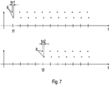
- the measuring points of the first sensor group are shown in the upper diagram and the measuring points of the second sensor group are shown as a function of time t in the lower diagram.
- the respective upper measuring series shows the measuring points of the respective first sensor (2.1, 3.1) of the respective sensor group and the lower measuring series shows the respective measuring points of the respective second sensor (2.2, 3.2) of the respective sensor group.
- the vehicle 1 travels in the direction of travel 9 on the concrete floor over the reinforcing bars 7.
- the vehicle advantageously travels at a constant speed v.
- the sensors (2.1, 2.2) of the first sensor group simultaneously detect a reinforcing rod 7.
- the sensors (3.1, 3.2) of the second sensor group simultaneously detect the reinforcing rod 7.
- the speed sensor preferably detects the speed v of the vehicle 1.
- the sensors (2.1, 2.2) of the first sensor group detect the reinforcement rod 7 at the same time, but the sensors (3.1, 3.2) of the second sensor group detect the reinforcement rod 7 with a time delay, the direction of travel 9 of the vehicle 1 was changed during the period of time ⁇ t .
- the vehicle 1 is aligned on the concrete floor in such a way that the reference lines 6 of the sensor groups are arranged at a non-vanishing angle ⁇ to a reinforcing rod 7.
- the reinforcement preferably has a multiplicity of reinforcing rods 7 arranged in parallel.
- the measuring points of the first sensor group are shown in the upper diagram and the measuring points of the second sensor group are shown as a function of time t in the lower diagram.
- the respective upper measuring series shows the measuring points of the respective first sensor (2.1, 3.1) of the respective sensor group and the lower measuring series shows the respective measuring points of the respective second sensor (2.2, 3.2) of the respective sensor group.
- the speed sensor preferably detects the speed v of the vehicle 1.
- the first and the second sensor (2.1, 2.2) of the first sensor group detect the reinforcing rod 7 offset in time by t ⁇ 1.
- the first and the second sensor (3.1, 3.2) of the second sensor group detect the reinforcing rod 7 offset in time by t ⁇ 2.
- Each sensor group preferably has a multiplicity of sensors (2.1, 2.2, 3.1, 3.2) which are each arranged on a respective reference line 6.
- sensors 2.1, 2.2, 3.1, 3.2
- signals from other reinforcing bars that cross the reinforcing bar 7 can be determined.
- a sensor that is permanent a reinforcing bar crossing the reinforcing bar 7 is detected, not taken into account in the calculation of the angles ⁇ 1 and ⁇ 2.
- the vehicle 1 For the further application that the vehicle 1 should repeatedly drive the same route, the vehicle 1 carries out a reference run at constant speed and determines measurement points along the entire route using one of the sensors (2.1, 2.2, 3.1, 3.2). A reference profile is determined by means of the measuring points of the reference run. The reference profile indicates an intensity of the signal from the reinforcement for each position on the route.
- the distances between the reinforcing bars 7 can be determined from the intensity maxima of the reference profile.
- the speed of the vehicle 1 can be determined from the time between two intensity maxima instead of by means of the speed sensor.
- the position of the vehicle 1 on the route is preferably also determined.
- measuring points of a profile section are determined by means of the sensor (2.1, 2.2, 3.1, 3.2) which was used during the reference run.
- This profile section is compared with the reference profile by the evaluation means 4, in particular by means of a correlation method. If the profile section clearly matches a section of the reference profile, then each measuring point of the profile section can be clearly assigned to a position on the route.
- the current position of the vehicle 1 is determined by comparing a current measurement point with the profile section and the assigned section of the reference profile.
Landscapes
- Engineering & Computer Science (AREA)
- Physics & Mathematics (AREA)
- Automation & Control Theory (AREA)
- Remote Sensing (AREA)
- Radar, Positioning & Navigation (AREA)
- Aviation & Aerospace Engineering (AREA)
- General Physics & Mathematics (AREA)
- Mathematical Physics (AREA)
- Mechanical Engineering (AREA)
- Transportation (AREA)
- Electromagnetism (AREA)
- Control Of Position, Course, Altitude, Or Attitude Of Moving Bodies (AREA)
- Length Measuring Devices With Unspecified Measuring Means (AREA)
- Radar Systems Or Details Thereof (AREA)
- Navigation (AREA)
Claims (15)
- Procédé de détermination de la direction (9) de déplacement d'un véhicule (1) au moyen d'un système affecté à la détermination de la direction de déplacement d'un véhicule,
ledit véhicule (1) étant disposé sur un sol en béton, avec faculté de déplacement,
lequel sol en béton est muni d'un moins une barre d'armature (7),
sachant que le véhicule (1) est équipé d'au moins un premier capteur (2.1) et d'un second capteur (2.2) d'un premier groupe de détection, qui sont implantés le long d'une première ligne de référence (6) en étant espacés l'un de l'autre d'une distance a1 ,
caractérisé par le fait que
la direction de déplacement est réputée parallèle à la barre d'armature (7), ou est associée à une autre valeur préétablie d'angle directionnel initial, jusqu'à ce que le véhicule (1) se déplace à une vitesse v au-dessus de ladite barre d'armature (7),
le premier capteur (2.1) détectant la barre d'armature (7) à un premier instant t1,
le second capteur (2.2) détectant ladite barre d'armature (7) à un deuxième instant t2 succédant notamment audit premier instant t1 dans le temps,
la différence temporelle tα1 , entre ledit premier instant t1 et ledit deuxième instant t2, étant alors déterminée,
sachant qu'un angle α1 indiquant, au premier instant et/ou au deuxième instant, l'angle entre la direction (9) de déplacement du véhicule (1) et la direction de l'étendue de la barre d'armature (7), est déterminé sur la base de ladite différence temporelle tα1 , de ladite vitesse v et de ladite distance a1 ,
ou bien que ladite direction de déplacement est déterminée comme étant parallèle à ladite barre d'armature (7). - Procédé selon la revendication 1,
caractérisé par le fait que
le véhicule (1) se déplace à vitesse v constante,
l'angle α1 étant calculé comme suit :
- Procédé selon l'une des revendications 1 ou 2,
caractérisé par le fait que
le véhicule (1) est doté d'un second groupe de détection, lequel second groupe de détection comprend au moins deux capteurs (3.1, 3.2) qui sont implantés le long d'une seconde ligne de référence (6) en étant espacés l'un de l'autre d'une distance a2 ,
le premier groupe de détection et ledit second groupe de détection étant agencés de façon telle que la première ligne de référence (6) et ladite seconde ligne de référence (6) soient disposées parallèlement l'une à l'autre et soient espacées l'une de l'autre de la distance x, un premier capteur (3.1) du second groupe de détection détectant la barre d'armature (7) à un troisième instant t3 succédant au deuxième instant t2 dans le temps,
un second capteur (3.2) dudit second groupe de détection détectant ladite barre d'armature (7) à un quatrième instant t4 succédant notamment audit troisième instant t3 dans le temps, la différence temporelle tα2, entre ledit troisième instant t3 et ledit quatrième instant t4, étant alors déterminée,
sachant qu'un angle α2 indiquant, au troisième instant et/ou au quatrième instant, l'angle entre la direction (9) de déplacement du véhicule (1) et la direction de l'étendue de la barre d'armature (7), est déterminé sur la base de ladite différence temporelle tα2, de la vitesse v et de ladite distance a2. - Procédé selon la revendication 3,
caractérisé par le fait que
le véhicule (1) se déplace à vitesse v constante,
l'angle α2 étant calculé comme suit :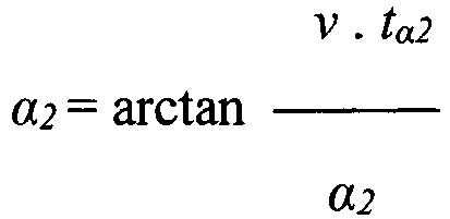
- Procédé selon la revendication 3 ou 4,
caractérisé par le fait que
le véhicule (1) utilise la différence entre les angles α1 et α2 pour la commande dudit véhicule (1),
laquelle différence entre les angles α1 et α2 indique une variation de la direction de déplacement (9) au cours du trajet x parcouru, c'est-à-dire un angle de braquage,
sachant notamment- que l'angle de braquage ainsi déterminé est régulé pour prendre une valeur de consigne, au moyen d'un régulateur dudit véhicule, un entraînement de braquage dudit véhicule étant réglé en conséquence,
et/ou- que ledit angle de braquage déterminé est surveillé quant à un dépassement inadmissible d'une valeur limite pouvant être préétablie. - Procédé selon au moins l'une des revendications 3 à 5,
caractérisé par le fait que
le laps de temps Δt est calculé au moyen de la vitesse v et de la distance x entre les groupes de détection, de la façon suivante :

sachant notamment que ladite valeur de seuil représente moins d'un cinquième ou moins d'un vingtième dudit laps de temps Δt. - Procédé conforme à au moins l'une des revendications 1 à 6, affecté à la détermination de la direction (9) de déplacement d'un véhicule (1),
caractérisé par le fait que
les étapes opératoires mentionnées ci-après, se succédant mutuellement dans le temps, sont exécutées pour déterminer la vitesse du véhicule (1) le long d'un trajet de déplacement :lors d'une première étape opératoire, le véhicule (1) effectue un parcours de référence à vitesse constante le long du trajet de déplacement, l'un des capteurs (2.1, 2.2, 3.1, 3.2) enregistrant alors des points de mesure le long dudit trajet de déplacement, chaque point de mesure d'un emplacement, sur ledit trajet de déplacement, affectant un signal à un ensemble de barres d'armature dans le sol en béton,lors d'une deuxième étape opératoire, un profil de référence dudit trajet de déplacement est déterminé sur la base des points de mesure spécifiés pendant ledit parcours de référence,lors d'une troisième étape opératoire, ledit véhicule (1) se déplace le long dudit trajet de déplacement et enregistre des points de mesure supplémentaires au moyen du capteur (2.1, 2.2, 3.1, 3.2) utilisé pendant ledit parcours de référence,lors d'une quatrième étape opératoire, un segment de profil est déterminé sur la base desdits points de mesure supplémentaires,lors d'une cinquième étape opératoire, ledit segment de profil est attribué de manière univoque à un segment dudit profil de référence, notamment au moyen d'un procédé de corrélation,lors d'une sixième étape opératoire, des emplacements, sur ledit trajet de déplacement, sont affectés de manière univoque audit véhicule, au moyen dudit segment de profil attribué audit profil de référence,lors d'une septième étape opératoire, la vitesse dudit véhicule (1) est déterminée sur la base desdits emplacements, sur ledit trajet de déplacement, et du laps de temps entre les points de mesure de ces emplacements. - Système dévolu à la mise en œuvre d'un procédé conforme à l'une des revendications 1 à 7, plus précisément affecté à la détermination de la direction (9) de déplacement d'un véhicule (1),
caractérisé par le fait que
ledit système inclut le véhicule (1) et un sol en béton pourvu d'un moins une barre d'armature (7),
ledit véhicule (1) étant disposé sur ledit sol en béton, avec faculté de déplacement,
lequel véhicule (1) comprend un moyen d'évaluation (4) et un premier groupe de détection équipé d'au moins deux capteurs (2.1, 2.2),
lesquels capteurs (2.1, 2.2) sont implantés avec espacement l'un de l'autre le long d'une première ligne de référence (6),
lesdits capteurs (2.1, 2.2) étant agencés en vue de la détection de ladite barre d'armature (7),
sachant que ledit moyen d'évaluation (4) est connecté aux capteurs (2.1, 2.2) et est agencé en vue de la détermination de la direction de déplacement (9) sur la base des signaux desdits capteurs (2.1, 2.2). - Système conforme à la revendication 8, affecté à la détermination de la direction (9) de déplacement d'un véhicule (1),
caractérisé par le fait que
le véhicule (1) comporte un second groupe de détection équipé d'au moins deux capteurs (3.1,3.2),
les capteurs (3.1, 3.2) dudit second groupe de détection étant implantés avec espacement l'un de l'autre le long d'une seconde ligne de référence (6),
sachant que la première ligne de référence (6) et ladite seconde ligne de référence (6) sont espacées l'une de l'autre et sont disposées parallèlement l'une à l'autre,
lesdits capteurs (3.1, 3.2) dudit second groupe de détection étant agencés en vue de détecter la barre d'armature (7),
sachant que le moyen d'évaluation (4) est connecté auxdits capteurs (3.1, 3.2) du second groupe de détection et est agencé en vue de la détermination de la direction de déplacement (9) sur la base des signaux desdits capteurs (3.1, 3.2) dudit second groupe de détection. - Système conforme à au moins l'une des revendications précédentes, affecté à la détermination de la direction (9) de déplacement d'un véhicule (1),
caractérisé par le fait que
les capteurs (2.1, 2.2, 3.1, 3.2) sont installés au niveau d'un plancher du véhicule (1) ; et/ou par le fait que
lesdits capteurs (2.1, 2.2, 3.1, 3.2) sont des capteurs radar et/ou des capteurs inductifs, agencés pour déterminer l'épaisseur et/ou la densité et/ou la profondeur de la barre d'armature (7) dans le sol en béton. - Système selon l'une des revendications 8 ou 9,
caractérisé par le fait que
le véhicule (1) est équipé d'une commande, ledit véhicule (1) se présentant notamment comme un véhicule de transport sans conducteur,
ladite commande du véhicule étant connectée au moyen d'évaluation (4). - Système selon l'une des revendications 8 à 10,
caractérisé par le fait que
le moyen d'évaluation (4) est doté d'une unité de calcul agencée en vue de calculer des fonctions trigonométriques ;
et/ou par le fait que
ledit moyen d'évaluation (4) est muni d'un moyen de chronométrage agencé en vue de la détermination du temps entre deux détections de la barre d'armature (7), notamment en vue de la détermination du temps entre l'instant de la détection de ladite barre d'armature (7) par le premier capteur, et l'instant de la détection de ladite barre d'armature (7) par le second capteur. - Système selon l'une des revendications 8 à 12,
caractérisé par le fait que
ledit système est muni d'un capteur de vitesses, en vue de déterminer la vitesse v du véhicule (1) dans la direction de déplacement (9). - Système selon l'une des revendications 8 à 13,
caractérisé par le fait que
le sol en béton compte une multiplicité de barres d'armature (7),
lesquelles barres d'armature (7) sont notamment disposées parallèlement les unes aux autres, et/ou agencées en treillis. - Système selon l'une des revendications 8 à 14,
caractérisé par le fait que
chaque groupe de détection compte une multiplicité de capteurs (2.1, 2.2, 3.1, 3.2),
le moyen d'évaluation (4) étant agencé en vue d'évaluer les signaux des capteurs (2.1, 2.2, 3.1, 3.2) des premier et second groupes de détection,
sachant notamment que ledit moyen d'évaluation (4) est agencé en vue de la sélection de signaux individuels émanant d'un groupe de détection, pour la détermination de la direction (9) de déplacement du véhicule (1).
Applications Claiming Priority (2)
| Application Number | Priority Date | Filing Date | Title |
|---|---|---|---|
| DE102016010879 | 2016-09-12 | ||
| PCT/EP2017/025211 WO2018046135A1 (fr) | 2016-09-12 | 2017-07-14 | Système et procédé pour conduire un véhicule |
Publications (2)
| Publication Number | Publication Date |
|---|---|
| EP3510462A1 EP3510462A1 (fr) | 2019-07-17 |
| EP3510462B1 true EP3510462B1 (fr) | 2021-07-07 |
Family
ID=59366367
Family Applications (1)
| Application Number | Title | Priority Date | Filing Date |
|---|---|---|---|
| EP17740623.8A Active EP3510462B1 (fr) | 2016-09-12 | 2017-07-14 | Système et procédé pour conduire un véhicule |
Country Status (5)
| Country | Link |
|---|---|
| US (1) | US11092969B2 (fr) |
| EP (1) | EP3510462B1 (fr) |
| CN (1) | CN109564431B (fr) |
| DE (1) | DE102017006686A1 (fr) |
| WO (1) | WO2018046135A1 (fr) |
Families Citing this family (2)
| Publication number | Priority date | Publication date | Assignee | Title |
|---|---|---|---|---|
| DE102017215646A1 (de) * | 2017-09-06 | 2019-03-07 | Kuka Deutschland Gmbh | Verfahren zum automatischen Fahren eines fahrerlosen Transportfahrzeugs auf einer Fahrbahn einer Gebäudedecke eines Gebäudes und fahrerloses Transportfahrzeug |
| DE102019123647A1 (de) * | 2019-09-04 | 2021-03-04 | Still Gesellschaft Mit Beschränkter Haftung | Verfahren zur Lokalisierung eines Fahrzeugs sowie Fahrzeug zur Durchführung des Verfahrens |
Family Cites Families (16)
| Publication number | Priority date | Publication date | Assignee | Title |
|---|---|---|---|---|
| US3008532A (en) * | 1958-01-17 | 1961-11-14 | Reed Res Inc | Automatic pilot for motor vehicles |
| US4079801A (en) * | 1973-10-11 | 1978-03-21 | National Research Development Corporation | Vehicle guidance systems |
| DE2445001C2 (de) | 1974-09-20 | 1982-09-16 | Robert Bosch Gmbh, 7000 Stuttgart | Anordnung zum Spurführen von gleisfreien Fahrzeugen |
| DE2506961C3 (de) | 1975-02-19 | 1981-09-10 | Robert Bosch Gmbh, 7000 Stuttgart | Anordnung zum Spurführen eines gleisfreien Fahrzeuges |
| SE465487B (sv) * | 1989-12-07 | 1991-09-16 | Goeran Lennart Bergqvist | Foerfarande och system foer navigering av obemannade fordon |
| US5404087A (en) | 1993-03-03 | 1995-04-04 | Sherman; Leigh E. | Automated guided vehicle wire guidance apparatus |
| DE4312434C2 (de) | 1993-03-06 | 2002-11-14 | Daimler Chrysler Ag | Anordnung zum induktiven Spurführen gleisunabhängiger Fahrzeuge |
| DE19938345C1 (de) * | 1999-08-13 | 2001-02-15 | Isocom Automationssysteme Gmbh | Verfahren und Vorrichtung zur Erfassung der Position von einem Fahrzeug in einem vorgegebenen Bereich, insbesondere einer Lagereinrichtung, sowie Lagerverwaltungsverfahren und -system |
| DE10049402A1 (de) | 2000-10-05 | 2002-05-08 | Graband & Partner Gmbh Dr | Verfahren zur Lageermittlung von Transportmitteln sowie Transportmittel und Baukörpern |
| ES2268122T3 (es) | 2001-12-12 | 2007-03-16 | Jervis B. Webb International Company | Sistema y procedimiento de guiado de vehiculos sin conductor. |
| CN1791527A (zh) * | 2003-05-21 | 2006-06-21 | 希尔霍尔茨传送电梯瑞士股份公司 | 导轨装置、道岔和具有磁致伸缩的传感器的输送装置 |
| DE102005008555B4 (de) | 2005-02-23 | 2016-09-15 | Sew-Eurodrive Gmbh & Co Kg | Verfahren zur Bestimmung einer Position |
| CN101603830A (zh) * | 2009-06-23 | 2009-12-16 | 广州市井源机电设备有限公司 | 自动导航小车系统及多任务控制方法 |
| CN102877401B (zh) * | 2012-09-17 | 2015-02-04 | 山东省交通科学研究所 | 连续配筋混凝土路面内钢筋变形的检测方法 |
| CN104044594B (zh) * | 2014-06-23 | 2016-08-17 | 中国北方车辆研究所 | 一种面向横向距离预警的运算装置 |
| CN104019825A (zh) * | 2014-06-23 | 2014-09-03 | 中国北方车辆研究所 | 一种路径规划的确定方法 |
-
2017
- 2017-07-14 EP EP17740623.8A patent/EP3510462B1/fr active Active
- 2017-07-14 US US16/332,730 patent/US11092969B2/en active Active
- 2017-07-14 CN CN201780049747.8A patent/CN109564431B/zh active Active
- 2017-07-14 DE DE102017006686.8A patent/DE102017006686A1/de active Pending
- 2017-07-14 WO PCT/EP2017/025211 patent/WO2018046135A1/fr not_active Ceased
Non-Patent Citations (1)
| Title |
|---|
| None * |
Also Published As
| Publication number | Publication date |
|---|---|
| EP3510462A1 (fr) | 2019-07-17 |
| US20190369638A1 (en) | 2019-12-05 |
| CN109564431B (zh) | 2022-12-02 |
| DE102017006686A1 (de) | 2018-03-15 |
| WO2018046135A1 (fr) | 2018-03-15 |
| US11092969B2 (en) | 2021-08-17 |
| CN109564431A (zh) | 2019-04-02 |
Similar Documents
| Publication | Publication Date | Title |
|---|---|---|
| EP1276626B2 (fr) | Procede de regulation de la vitesse d'un vehicule en fonction de la distance | |
| EP1853453B1 (fr) | Procede pour determiner la plausibilite d'objets dans des systemes d'assistance a la conduite | |
| DE102008058652B4 (de) | Verfahren zur Berechnung der Einparktrajektorie eines Kraftfahrzeugs und Fahrzeugassistenzvorrichtung | |
| EP3094531B1 (fr) | Procédé pour faire fonctionner un véhicule | |
| WO2016135161A1 (fr) | Système d'aide au stationnement pouvant reconnaître une place de stationnement universelle | |
| EP2953838A1 (fr) | Procede et dispositif pour stationner un véhicule à moteur en marche avant sur une place de stationnement en bataille | |
| DE102016106983A1 (de) | Verfahren zum Erkennen eines möglichen Spurwechselmanövers eines Zielfahrzeugs, Steuereinrichtung, Fahrerassistenzsystem sowie Kraftfahrzeug | |
| WO2016020343A1 (fr) | Procédé de reconnaissance d'au moins un objet dans une zone environnante d'un véhicule automobile au moyen d'un capteur à ultrasons, système d'aide à la conduite et véhicule automobile | |
| DE102015007592B4 (de) | Trajektoriebasierte Fahrwerksregelung | |
| DE102017222017A1 (de) | Verfahren und System zum Ermitteln und Bereitstellen eines Bodenprofils | |
| EP1755921B1 (fr) | Procede et dispositif d'assistance pour faciliter une operation de stationnement d'un vehicule | |
| EP1602530B1 (fr) | Méthode pour assister le stationnement d'un véhicule | |
| DE102008003039A1 (de) | Verfahren zur Verkehrszustandsbestimmung in einem Fahrzeug | |
| DE102015212296A1 (de) | Verfahren zum Ermitteln einer Nutzbreite eines Straßenabschnitts | |
| DE102016013972A1 (de) | Fahrerassistenzsystem und -verfahren | |
| DE102009039691A1 (de) | Verfahren und Vorrichtung zum Einparken eines Kraftfahrzeugs | |
| DE102011109712A1 (de) | Verfahren und Vorrichtung zum unterstützten Einparken eines Kraftfahrzeugs | |
| DE102014210174A1 (de) | Bestimmen eines kritischen Fahrzeugzustands und einer Fahrzeugmindestentfernung | |
| EP3510462B1 (fr) | Système et procédé pour conduire un véhicule | |
| EP2910445B1 (fr) | Procédé d'assistance d'un conducteur pour passer dans une voie de circulation rétrécie et système d'assistance du conducteur | |
| DE102015222784A1 (de) | Spurhalteassistenzsystem für ein Fahrzeug und Verfahren zu dessen Steuerung | |
| DE102008062796A1 (de) | Fahrerassistenzsystem und Verfahren zum Betreiben eines Fahrzeugs | |
| EP3279051B1 (fr) | Système de commande et procédé de commande destiné à sélectionner et à suivre un véhicule automobile | |
| DE102017220486B4 (de) | Verfahren zur Adaption einer vorbestimmten Referenzlinie für ein Kraftfahrzeug und Vorrichtung | |
| DE102017218487A1 (de) | Verfahren zum Betrieb eines Inertialsensorsystems, Inertialsystem und Fahrzeug mit Inertialsystem |
Legal Events
| Date | Code | Title | Description |
|---|---|---|---|
| STAA | Information on the status of an ep patent application or granted ep patent |
Free format text: STATUS: UNKNOWN |
|
| STAA | Information on the status of an ep patent application or granted ep patent |
Free format text: STATUS: THE INTERNATIONAL PUBLICATION HAS BEEN MADE |
|
| PUAI | Public reference made under article 153(3) epc to a published international application that has entered the european phase |
Free format text: ORIGINAL CODE: 0009012 |
|
| STAA | Information on the status of an ep patent application or granted ep patent |
Free format text: STATUS: REQUEST FOR EXAMINATION WAS MADE |
|
| 17P | Request for examination filed |
Effective date: 20190412 |
|
| AK | Designated contracting states |
Kind code of ref document: A1 Designated state(s): AL AT BE BG CH CY CZ DE DK EE ES FI FR GB GR HR HU IE IS IT LI LT LU LV MC MK MT NL NO PL PT RO RS SE SI SK SM TR |
|
| AX | Request for extension of the european patent |
Extension state: BA ME |
|
| DAV | Request for validation of the european patent (deleted) | ||
| DAX | Request for extension of the european patent (deleted) | ||
| GRAP | Despatch of communication of intention to grant a patent |
Free format text: ORIGINAL CODE: EPIDOSNIGR1 |
|
| STAA | Information on the status of an ep patent application or granted ep patent |
Free format text: STATUS: GRANT OF PATENT IS INTENDED |
|
| INTG | Intention to grant announced |
Effective date: 20210223 |
|
| GRAS | Grant fee paid |
Free format text: ORIGINAL CODE: EPIDOSNIGR3 |
|
| GRAA | (expected) grant |
Free format text: ORIGINAL CODE: 0009210 |
|
| STAA | Information on the status of an ep patent application or granted ep patent |
Free format text: STATUS: THE PATENT HAS BEEN GRANTED |
|
| AK | Designated contracting states |
Kind code of ref document: B1 Designated state(s): AL AT BE BG CH CY CZ DE DK EE ES FI FR GB GR HR HU IE IS IT LI LT LU LV MC MK MT NL NO PL PT RO RS SE SI SK SM TR |
|
| REG | Reference to a national code |
Ref country code: GB Ref legal event code: FG4D Free format text: NOT ENGLISH |
|
| REG | Reference to a national code |
Ref country code: AT Ref legal event code: REF Ref document number: 1409194 Country of ref document: AT Kind code of ref document: T Effective date: 20210715 |
|
| REG | Reference to a national code |
Ref country code: DE Ref legal event code: R096 Ref document number: 502017010857 Country of ref document: DE |
|
| REG | Reference to a national code |
Ref country code: IE Ref legal event code: FG4D Free format text: LANGUAGE OF EP DOCUMENT: GERMAN |
|
| REG | Reference to a national code |
Ref country code: LT Ref legal event code: MG9D |
|
| REG | Reference to a national code |
Ref country code: NL Ref legal event code: MP Effective date: 20210707 |
|
| PG25 | Lapsed in a contracting state [announced via postgrant information from national office to epo] |
Ref country code: RS Free format text: LAPSE BECAUSE OF FAILURE TO SUBMIT A TRANSLATION OF THE DESCRIPTION OR TO PAY THE FEE WITHIN THE PRESCRIBED TIME-LIMIT Effective date: 20210707 Ref country code: SE Free format text: LAPSE BECAUSE OF FAILURE TO SUBMIT A TRANSLATION OF THE DESCRIPTION OR TO PAY THE FEE WITHIN THE PRESCRIBED TIME-LIMIT Effective date: 20210707 Ref country code: HR Free format text: LAPSE BECAUSE OF FAILURE TO SUBMIT A TRANSLATION OF THE DESCRIPTION OR TO PAY THE FEE WITHIN THE PRESCRIBED TIME-LIMIT Effective date: 20210707 Ref country code: LT Free format text: LAPSE BECAUSE OF FAILURE TO SUBMIT A TRANSLATION OF THE DESCRIPTION OR TO PAY THE FEE WITHIN THE PRESCRIBED TIME-LIMIT Effective date: 20210707 Ref country code: BG Free format text: LAPSE BECAUSE OF FAILURE TO SUBMIT A TRANSLATION OF THE DESCRIPTION OR TO PAY THE FEE WITHIN THE PRESCRIBED TIME-LIMIT Effective date: 20211007 Ref country code: PT Free format text: LAPSE BECAUSE OF FAILURE TO SUBMIT A TRANSLATION OF THE DESCRIPTION OR TO PAY THE FEE WITHIN THE PRESCRIBED TIME-LIMIT Effective date: 20211108 Ref country code: NL Free format text: LAPSE BECAUSE OF FAILURE TO SUBMIT A TRANSLATION OF THE DESCRIPTION OR TO PAY THE FEE WITHIN THE PRESCRIBED TIME-LIMIT Effective date: 20210707 Ref country code: NO Free format text: LAPSE BECAUSE OF FAILURE TO SUBMIT A TRANSLATION OF THE DESCRIPTION OR TO PAY THE FEE WITHIN THE PRESCRIBED TIME-LIMIT Effective date: 20211007 Ref country code: FI Free format text: LAPSE BECAUSE OF FAILURE TO SUBMIT A TRANSLATION OF THE DESCRIPTION OR TO PAY THE FEE WITHIN THE PRESCRIBED TIME-LIMIT Effective date: 20210707 Ref country code: ES Free format text: LAPSE BECAUSE OF FAILURE TO SUBMIT A TRANSLATION OF THE DESCRIPTION OR TO PAY THE FEE WITHIN THE PRESCRIBED TIME-LIMIT Effective date: 20210707 |
|
| PG25 | Lapsed in a contracting state [announced via postgrant information from national office to epo] |
Ref country code: PL Free format text: LAPSE BECAUSE OF FAILURE TO SUBMIT A TRANSLATION OF THE DESCRIPTION OR TO PAY THE FEE WITHIN THE PRESCRIBED TIME-LIMIT Effective date: 20210707 Ref country code: LV Free format text: LAPSE BECAUSE OF FAILURE TO SUBMIT A TRANSLATION OF THE DESCRIPTION OR TO PAY THE FEE WITHIN THE PRESCRIBED TIME-LIMIT Effective date: 20210707 Ref country code: GR Free format text: LAPSE BECAUSE OF FAILURE TO SUBMIT A TRANSLATION OF THE DESCRIPTION OR TO PAY THE FEE WITHIN THE PRESCRIBED TIME-LIMIT Effective date: 20211008 |
|
| REG | Reference to a national code |
Ref country code: CH Ref legal event code: PL |
|
| REG | Reference to a national code |
Ref country code: BE Ref legal event code: MM Effective date: 20210731 |
|
| REG | Reference to a national code |
Ref country code: DE Ref legal event code: R097 Ref document number: 502017010857 Country of ref document: DE |
|
| PG25 | Lapsed in a contracting state [announced via postgrant information from national office to epo] |
Ref country code: LI Free format text: LAPSE BECAUSE OF NON-PAYMENT OF DUE FEES Effective date: 20210731 Ref country code: DK Free format text: LAPSE BECAUSE OF FAILURE TO SUBMIT A TRANSLATION OF THE DESCRIPTION OR TO PAY THE FEE WITHIN THE PRESCRIBED TIME-LIMIT Effective date: 20210707 Ref country code: CH Free format text: LAPSE BECAUSE OF NON-PAYMENT OF DUE FEES Effective date: 20210731 |
|
| PLBE | No opposition filed within time limit |
Free format text: ORIGINAL CODE: 0009261 |
|
| STAA | Information on the status of an ep patent application or granted ep patent |
Free format text: STATUS: NO OPPOSITION FILED WITHIN TIME LIMIT |
|
| PG25 | Lapsed in a contracting state [announced via postgrant information from national office to epo] |
Ref country code: SM Free format text: LAPSE BECAUSE OF FAILURE TO SUBMIT A TRANSLATION OF THE DESCRIPTION OR TO PAY THE FEE WITHIN THE PRESCRIBED TIME-LIMIT Effective date: 20210707 Ref country code: SK Free format text: LAPSE BECAUSE OF FAILURE TO SUBMIT A TRANSLATION OF THE DESCRIPTION OR TO PAY THE FEE WITHIN THE PRESCRIBED TIME-LIMIT Effective date: 20210707 Ref country code: RO Free format text: LAPSE BECAUSE OF FAILURE TO SUBMIT A TRANSLATION OF THE DESCRIPTION OR TO PAY THE FEE WITHIN THE PRESCRIBED TIME-LIMIT Effective date: 20210707 Ref country code: MC Free format text: LAPSE BECAUSE OF FAILURE TO SUBMIT A TRANSLATION OF THE DESCRIPTION OR TO PAY THE FEE WITHIN THE PRESCRIBED TIME-LIMIT Effective date: 20210707 Ref country code: LU Free format text: LAPSE BECAUSE OF NON-PAYMENT OF DUE FEES Effective date: 20210714 Ref country code: EE Free format text: LAPSE BECAUSE OF FAILURE TO SUBMIT A TRANSLATION OF THE DESCRIPTION OR TO PAY THE FEE WITHIN THE PRESCRIBED TIME-LIMIT Effective date: 20210707 Ref country code: CZ Free format text: LAPSE BECAUSE OF FAILURE TO SUBMIT A TRANSLATION OF THE DESCRIPTION OR TO PAY THE FEE WITHIN THE PRESCRIBED TIME-LIMIT Effective date: 20210707 Ref country code: AL Free format text: LAPSE BECAUSE OF FAILURE TO SUBMIT A TRANSLATION OF THE DESCRIPTION OR TO PAY THE FEE WITHIN THE PRESCRIBED TIME-LIMIT Effective date: 20210707 |
|
| 26N | No opposition filed |
Effective date: 20220408 |
|
| GBPC | Gb: european patent ceased through non-payment of renewal fee |
Effective date: 20211007 |
|
| PG25 | Lapsed in a contracting state [announced via postgrant information from national office to epo] |
Ref country code: IT Free format text: LAPSE BECAUSE OF FAILURE TO SUBMIT A TRANSLATION OF THE DESCRIPTION OR TO PAY THE FEE WITHIN THE PRESCRIBED TIME-LIMIT Effective date: 20210707 Ref country code: IE Free format text: LAPSE BECAUSE OF NON-PAYMENT OF DUE FEES Effective date: 20210714 Ref country code: GB Free format text: LAPSE BECAUSE OF NON-PAYMENT OF DUE FEES Effective date: 20211007 Ref country code: BE Free format text: LAPSE BECAUSE OF NON-PAYMENT OF DUE FEES Effective date: 20210731 |
|
| PG25 | Lapsed in a contracting state [announced via postgrant information from national office to epo] |
Ref country code: CY Free format text: LAPSE BECAUSE OF FAILURE TO SUBMIT A TRANSLATION OF THE DESCRIPTION OR TO PAY THE FEE WITHIN THE PRESCRIBED TIME-LIMIT Effective date: 20210707 |
|
| PG25 | Lapsed in a contracting state [announced via postgrant information from national office to epo] |
Ref country code: HU Free format text: LAPSE BECAUSE OF FAILURE TO SUBMIT A TRANSLATION OF THE DESCRIPTION OR TO PAY THE FEE WITHIN THE PRESCRIBED TIME-LIMIT; INVALID AB INITIO Effective date: 20170714 |
|
| REG | Reference to a national code |
Ref country code: AT Ref legal event code: MM01 Ref document number: 1409194 Country of ref document: AT Kind code of ref document: T Effective date: 20220714 |
|
| PG25 | Lapsed in a contracting state [announced via postgrant information from national office to epo] |
Ref country code: AT Free format text: LAPSE BECAUSE OF NON-PAYMENT OF DUE FEES Effective date: 20220714 |
|
| REG | Reference to a national code |
Ref country code: DE Ref legal event code: R079 Ref document number: 502017010857 Country of ref document: DE Free format text: PREVIOUS MAIN CLASS: G05D0001020000 Ipc: G05D0001430000 |
|
| PG25 | Lapsed in a contracting state [announced via postgrant information from national office to epo] |
Ref country code: MK Free format text: LAPSE BECAUSE OF FAILURE TO SUBMIT A TRANSLATION OF THE DESCRIPTION OR TO PAY THE FEE WITHIN THE PRESCRIBED TIME-LIMIT Effective date: 20210707 |
|
| PG25 | Lapsed in a contracting state [announced via postgrant information from national office to epo] |
Ref country code: MT Free format text: LAPSE BECAUSE OF FAILURE TO SUBMIT A TRANSLATION OF THE DESCRIPTION OR TO PAY THE FEE WITHIN THE PRESCRIBED TIME-LIMIT Effective date: 20210707 |
|
| PGFP | Annual fee paid to national office [announced via postgrant information from national office to epo] |
Ref country code: FR Payment date: 20250610 Year of fee payment: 9 |
|
| PGFP | Annual fee paid to national office [announced via postgrant information from national office to epo] |
Ref country code: DE Payment date: 20250731 Year of fee payment: 9 |
|
| PG25 | Lapsed in a contracting state [announced via postgrant information from national office to epo] |
Ref country code: TR Free format text: LAPSE BECAUSE OF FAILURE TO SUBMIT A TRANSLATION OF THE DESCRIPTION OR TO PAY THE FEE WITHIN THE PRESCRIBED TIME-LIMIT Effective date: 20210707 |