EP3512991B1 - Mécanisme de préhension de trame pour métiers à tisser sans navette - Google Patents
Mécanisme de préhension de trame pour métiers à tisser sans navette Download PDFInfo
- Publication number
- EP3512991B1 EP3512991B1 EP17850359.5A EP17850359A EP3512991B1 EP 3512991 B1 EP3512991 B1 EP 3512991B1 EP 17850359 A EP17850359 A EP 17850359A EP 3512991 B1 EP3512991 B1 EP 3512991B1
- Authority
- EP
- European Patent Office
- Prior art keywords
- weft
- shaft
- cam
- weaving machine
- gripping mechanism
- Prior art date
- Legal status (The legal status is an assumption and is not a legal conclusion. Google has not performed a legal analysis and makes no representation as to the accuracy of the status listed.)
- Active
Links
Images


Classifications
-
- D—TEXTILES; PAPER
- D03—WEAVING
- D03D—WOVEN FABRICS; METHODS OF WEAVING; LOOMS
- D03D47/00—Looms in which bulk supply of weft does not pass through shed, e.g. shuttleless looms, gripper shuttle looms, dummy shuttle looms
- D03D47/12—Looms in which bulk supply of weft does not pass through shed, e.g. shuttleless looms, gripper shuttle looms, dummy shuttle looms wherein single picks of weft thread are inserted, i.e. with shedding between each pick
- D03D47/125—Weft holding devices
Definitions
- Present invention relates to textile engineering field and more particularly to the arrangements for tensioning of weft on shuttle less weaving machines. For many decades, catch selvedges or false selvedges are the only resort available for this purpose on shuttle-less weaving machines.
- the invention refers to a Weft Gripping mechanism for use on rapier type shuttle-less weaving machines. There is no such or similar device in existence today and the need for such a mechanism arises from the key points disadvantages of existing systems explained below further.
- DE 90 15 788 U1 discloses a device on weaving machines, which serves to actuate working elements arranged on the sley for the weft thread insertion.
- the actuating device is preferably used on non-shuttle weaving machines whose weft insertion is carried out with bar or band rapiers. This device is intended to clamp the weft between the weft scissors and the supply bobbins in order to avoid the weft thread falling off.
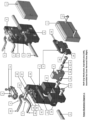
- Patent Illustration comprises 7 Diagrams:
- Patent Illustration Diagram 1 Weft Grip Mechanism, Exploded view (left), Assembled but Cover Removed View (Right)
- the body (1) of weft Grip Mechanism which is mounted securely on a part (numbered 16 and explained further) which is mounted directly on the sley bracket of the weaving machine in such a way that it can be moved sideways at desired position relative to the selvedge of the fabric being woven and can be locked in that place for operation. This is better explained in detail in Description of Patent Illustration 2 below.
- the body (1) has following details built in, hole (1A) is provided in weft grip mechanism body (1) for shaft (8), a Projection (1B) is provided on the body (1) for arresting plate cam (2) and allowing a sideways motion to the plate cam (2), a small space (1C) for slider part (3) is provided on body (1).
- a Suitable number of holes (1D) are provided in the body so that mounting fasteners (12) of the Cover (7) as explained further.
- Plate Cam (2) has following details built in to it.
- a Locking place (2A) is provided for slider part (3)
- a step (2B) is provided for mating with body (1) at (1B)
- two cam slots (2C) are provided for guiding and moving the pins (4B and 5B)
- these pins (4B and 5B) are either integrally built or assembled on weft grip levers (4 and 5) explained further.
- Slider part (3) which gets affixed to the shaft 8 and has following details built on to it.
- 3A is hole through which shaft 8 passes and gets fitted
- 3B is a cross hole through which a part 9 passes through in order to fix the slider 3 to shaft 8.
- the Weft Grip lever Lower (4) which has following details built in to it, A central cylinder portion (4A) which is a pivot for movement of this lever, a cylindrical projection (4C) provided on the motion input lever (4B) to mate with cam slots (2C), and a grip arm (4D) is provided which helps gripping the weft thread in conjunction with Weft Grip Lever upper (5) described further.
- the Weft Grip lever Upper (5) which has following details built in to it, A central cylinder portion (5A) which is a pivot for movement of this lever, a cylindrical projection (5C) re provided on the motion input lever (5B) to mate with cam slots (2C), and a grip arm (5D) is provided which helps gripping the weft thread in conjunction with Weft Grip Lever lower (4) described earlier.
- Bearing cap (6) for Weft Grip Levers (4 and 5) is devised and intended to clamp the cylindrical portion (4A and 5A)
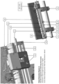
- Patent Illustration Diagram 2
- Sley Shaft (14) provides a mounting for several Sley shaft brackets (15) on which Tee slot part (16) mounted directly on sley brackets (15), the tee slot (16A) of the tee slot part (16) provides the mounting for entire Weft Grip mechanism by means of fasteners (13) in such a manner that it can be affixed to the tee slot in several lateral positions as per fabric width woven on the weaving machine.
- the Extruded Sley profile (17) is also mounted on the sley brackets (15).
- the tee slot part (16) has the small end bearing brackets (18) mounted on both sides of it which provide a sliding support to the shaft (8), another Intermediate support (19) is also provided for shaft (8) to reduce span length and to avoid buckling of shaft (8), this support(19) is also adjustable laterally based on working position of the weft grip mechanism on the tee slot part (16).
- Guide block and rapier tape guide assembly (20) along with Tape Guide plates (21) for rapier and, weaving reed (22) is also mounted on the sley profile (17).
- the weft grip mechanism is so adjusted widthwise in such a manner that the upper and lower weft grip levers are in between two tape guide plates and are not fouling with the plates during opening and closing operation of the same.
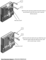
- Patent Illustration Diagram 3
- the small end brackets for shaft (8) are clamped to tee slot part (16) by means of fasteners (16B), these were not visible in any of the earlier views.
- the diagram mainly shows Space for weft carrying media between weft grip lever lower (4) and weft grip lever upper (5) for passing of rapier head and tape through the opened weft grip levers, the view is aligned as if it is seen by the incoming rapier head.
- Patent Illustration Diagram 4
- Shaft (8) carries a Clamping collar Stopper (23A), Clamping Collar (23B) for preloading and return spring (23C) arranged in such a manner that spring (23C) itself executes the return action on shaft (8) to keep it at normal pushed out condition.
- the force of spring (23C) is also the force used for gripping the weft.
- the diagram also elaborates placement of weft grip mechanism in such a manner that the weft grip levers are working between two adjacent tape guides (21).
- Patent Illustration Diagram 5
- This figure shows the driving arrangement of weft grip mechanism.
- Weft Grip Driving Surface Cam assembly is mounted on the machine frame/body and has a setting provision wherein the timing of the weft grip mechanism can be set in a angular advance or retard position relative to the machine.
- the surface cam (24) having a cam plate (24A) and a cylindrical projection (24B) is clamped by a Clamping and setting disk (25) which is diametrically locked and axially free to move on the surface cam cylindrical projection (24B) which is on the other side of the machine frame / body in such a manner that fastening of the screws will sandwich the machine frame between the surface cam body (24A) and clamping Disk (25).
- Cam Cylindrical projection (24B) and Clamping disk (25) is essential because rotating this disk should also apply equal rotation to the cam.
- Swing Lever (26) has a projection (26A) for connection with the connecting rod (31) and an Axial driving shaft (27) passes through the swing lever (26) and is diametrically locked with the swing lever but it is free to slide along its axis and the shaft is spring loaded to remain pressed against the surface cam (24A).
- Axial drive shaft (27) for weft grip mechanism bears a Cam follower mounting clamp (28), provides a seating for return spring (29 ), stopper (30) with a spring mounting disk is fitted on on shaft (27), further connecting rod (31 ) for Swing link (26) gets motion for the swing shaft through connecting rod having big end (31A) and connecting rod small end (31B), the big end of which is mounted on eccentric cam (32) which is in turn mounted on a machine shaft (33) is running at weaving cycle speed.
- WORKING The connecting rod (31) mounted on the eccentric (32) brings an oscillating motion to the swing lever (26) and the same is transferred to the shaft (27) as this shaft is diametrically locked with swing lever (26).
- the cam plate (24A) has a cam projection which is better seen and explained in diagram 6 below, this projection causes the follower (28A) to get pressed backward or forward as it follows the cam surface, pre load of the spring (29) keeps the shaft forcefully pressed on the cam and thus it also drives / presses the shaft (8) depending upon its position on the surface cam.
- the timing, as said earlier is set by means of rotating and clamping the cam along with the setting and clamping disk and locking of fasteners (25B).
- Patent Illustration Diagram 6 is a diagrammatic representation of
- the closed position remains intact during the beat up operation.
- the weft grip mechanism is driven to open position, and as soon as the rapiers exit the shed after transfer of thread, the weft grip is timed to close, coinciding with the gripper opening block timing.
- Patent Illustration Diagram 7
- the weft grip described in above primary embodiment and best mode of this invention is on two axes of upper and lower weft grip levers.
- an alternative embodiment should also be described where in the two axes of the two weft grip upper and lower levers coincide with each other by a hollow shaft in shaft arrangement as shown in diagram 7.
- Another alternative embodiment of this mechanism is in the driving mechanism, wherein the connecting rod connection between the swing lever, connecting rod and the shaft can be replaced by a rack and pinion arrangement where in the shaft shall bear the pinion gear and the connecting rod will be replaced by the rack gear oscillating to and fro path imparting a rotary swing motion to the shaft in order to move the follower bearing over the surface cam in the same fashion.
- Patent Illustration Diagram 1 Weft Grip Mechanism, Exploded view (left), Assembled but Cover Removed View (Right)
- Patent Illustration Diagram 2
- Patent Illustration Diagram 3
- Patent Illustration Diagram 4
- Patent Illustration Diagram 5
- Patent Illustration Diagram 6 Weft Grip and its drive, at open and closed positions
Landscapes
- Engineering & Computer Science (AREA)
- Textile Engineering (AREA)
- Looms (AREA)
Claims (14)
- Métier à tisser sans navette comprenant un corps (1) et un mécanisme de préhension de trame pour saisir un fil de trame par des moyens mécaniques avant qu'il ne soit coupé à longueur pour être monté sur un battant oscillant du métier à tisser sans navette, dans lequel le mécanisme de préhension de trame comprend un mécanisme d'entraînement qui est conçu pour être monté stationnaire sur le corps de métier à tisser ;
caractérisé en ce que :le mécanisme de préhension de trame comprend une paire de leviers de préhension de trame (4, 5) sur le côté sortie de l'insertion de trame pour contrôler la tension de trame pendant le battage avant qu'elle ne soit coupée à longueur, est placé sur le battant oscillant au moyen d'une partie de fente en té (16) du battant oscillant, la partie de fente en té (16) comprenant une fente en té (16A), ayant une longueur qui facilite les ajustements latéraux du mécanisme de préhension de trame ;le mécanisme d'entraînement ouvre ou ferme la pince de trame uniquement lorsque le battant oscillant est au niveau de la position centrale arrière ou position d'insertion de trame ; etle mécanisme de préhension de trame est dimensionné de manière à ne créer aucune gêne pour les autres pièces de métier à tisser ;dans lequel le corps (1) du mécanisme de préhension de trame comprend des attaches (13) pour la fixation sur le battant oscillant au moyen de la partie de fente en té (16), un arbre (8) passe à travers un trou (1A) dimensionné de manière appropriée dans le corps (1) de telle manière qu'une partie coulisseau (3) est en prise avec l'arbre (8), au niveau du trou (3A) dans la partie coulisseau (3), et il reste dans un évidement (1C) au niveau d'une position proche du centre du corps (1), en outre, cette partie coulisseau (3) est fixée à l'arbre (8) au moyen d'un manchon de serrage (9) et d'au moins une attache (10), de telle manière que la partie coulisseau (3) se déplace en même temps que l'arbre (8) mais à l'intérieur de l'évidement (IC), un levier de préhension de trame inférieur (4) et un levier de préhension de trame supérieur (5) sont montés sur le corps (1) au moyen d'un chapeau de palier (6) et d'attaches (11) de telle manière qu'ils peuvent osciller librement selon un angle compris entre 15 et 45 degrés autour de leurs axes et supports de pivotement (4A et 5A), une came à plaque (2) repose sur le corps (1) de telle manière qu'une face (2B) est en butée avec la surface inférieure d'une saillie (1B) et les broches (4B et 5B) viennent en prise dans les fentes (2C) de la came à plaque (2), la came à plaque est également montée de telle manière qu'une encoche (2A) vient en prise avec la partie coulisseau (3) et le mouvement de l'arbre (8) est ainsi transféré à la came à plaque (2), le mouvement de va-et-vient de l'arbre (8) est ainsi transféré à la partie coulisseau (3), puis à la came à plaque (2) puis aux leviers inférieur et supérieur (4 et 5) des pinces de trame par un accouplement mécanique entre les fentes (2C) et les broches (4B et 5B), la pince de trame peut ainsi s'ouvrir et se fermer en fonction de la position de l'arbre (8) de manière fiable ;dans lequel le mécanisme de préhension de trame est conçu pour être monté sur le battant oscillant, le système d'entraînement pour le mécanisme de préhension de trame est conçu pour être monté sur le corps stationnaire de métier à tisser et est constitué d'une bielle (31) montée sur une came excentrique (32), qui amène un mouvement oscillant à un levier pivotant (26) qui est transféré à un arbre d'entraînement axial (27), cet arbre d'entraînement axial (27) est diamétralement verrouillé avec le levier pivotant (26) au moyen d'une liaison à voie de clavette ou d'une liaison cannelée ou d'une liaison d'arbre triangulaire ou polygonale, le levier pivotant (26) est correctement guidé dans le corps de métier et est libre de tourner ou d'osciller, une plaque à came (24A) comporte une saillie de came qui amène un suiveur (28A) à être pressé vers l'arrière ou vers l'avant lorsqu'il suit une came de surface (24), la précharge d'un ressort d'activation (29) maintient l'arbre pressé avec force sur la came à plaque (2), entraînant ou pressant ainsi l'arbre (8) en fonction de sa position sur la came de surface (24),dans lequel le mécanisme de préhension de trame comprend un suiveur de came de face et un arbre entraîné par un mécanisme à pignon et crémaillère, dans lequel le mécanisme de préhension de trame est synchronisé avec précision en faisant fonctionner le métier au micro-ralenti ou en réglant la synchronisation ;dans lequel le levier pivotant (26) présente une saillie (26A) pour la liaison avec la bielle (31) et l'arbre d'entraînement axial (27) traverse le levier pivotant (26) et l'arbre d'entraînement axial (27) est diamétralement verrouillé avec le levier pivotant (26) mais l'arbre d'entraînement axial (27) est libre de coulisser le long de son axe et l'arbre est chargé par ressort pour rester pressé contre la came de surface (24A), dans lequel l'arbre d'entraînement axial (27) pour le mécanisme de préhension de trame porte un collier de montage de suiveur de came (28) et fournit un siège pour le ressort d'activation (29), dans lequel une butée (30) avec un disque de montage à ressort est ajustée sur l'arbre d'entraînement axial (27), et dans lequel la bielle (31) pour le levier pivotant (26) reçoit le mouvement de l'arbre d'entraînement axial (27) par l'intermédiaire de la bielle (31) ayant une grande extrémité (31A) et une petite extrémité (31B), dans lequel la grande extrémité (31A) de la bielle (31) est montée sur la came excentrique (32) qui est à son tour conçue pour être montée sur un arbre de métier (33) qui tourne à la vitesse du cycle de tissage ;dans lequel le mécanisme de préhension de trame a une épaisseur dans une direction parallèle aux supports de pivotement (4A, 5A), et dans lequel l'épaisseur du mécanisme de préhension de trame est inférieure à la longueur de la bielle (31). - Métier à tisser selon la revendication 1, dans lequel, afin d'exécuter la préhension du fil de trame, les leviers de préhension de trame portent une doublure souple en matériau polymère ou en caoutchouc de sorte que le fil peut être saisi par friction ; ou des leviers de préhension métalliques avec une surface de préhension ferme formée soit par usinage, soit par meulage de la surface de préhension.
- Métier à tisser selon la revendication 1, dans lequel les leviers de préhension de trame comprennent un agencement de leviers avec des arbres guidés et situés séparément des leviers de préhension de trame supérieur et inférieur avec un chapeau de palier séparé (6).
- Métier à tisser selon la revendication 1, dans lequel les leviers de préhension de trame comprennent deux arbres s'étendant coaxialement l'un à l'intérieur de l'autre sur un axe de fonctionnement.
- Métier à tisser selon l'une quelconque des revendications 1 à 4, dans lequel la synchronisation des pinces de trame est réglée au moyen de la rotation et du resserrage de la came à plaque (2) conjointement avec un disque de serrage et de réglage (25) et du verrouillage des attaches (25B).
- Métier à tisser selon la revendication 1, dans lequel un ensemble came de surface d'entraînement de pince de trame présente une disposition de réglage dans laquelle la synchronisation du mécanisme de préhension de trame peut être réglée dans une position d'avance ou de retard angulaire par rapport au métier.
- Métier à tisser selon l'une quelconque des revendications 1 à 6, dans lequel la came de surface (24) comportant la plaque à came (24A) et une saillie cylindrique de came (24B) est serrée par le disque de serrage et de réglage (25) qui est diamétralement verrouillé et libre de se déplacer axialement sur la surface de la saillie cylindrique de came (24B) qui se trouve de l'autre côté du châssis ou du corps de métier de telle manière que l'attache de la vis (25B) prendra en sandwich le châssis de métier entre le corps de came de surface (24A) et le disque de serrage (25).
- Métier à tisser selon la revendication 7, dans lequel le verrouillage diamétral entre la saillie cylindrique de came (24B) et le disque de serrage (25) est réalisé au moyen d'une liaison à voie de clavette ou d'une liaison cannelée ou d'une liaison d'arbre triangulaire ou polygonale, et la rotation du disque de serrage (25) applique une rotation égale à la came à plaque (2), et en outre, une pluralité de trous radiaux (25A) sur la périphérie du disque de serrage facilitent le mouvement de réglage.
- Métier à tisser selon l'une quelconque des revendications 1 à 8, dans lequel, lorsque la pince de trame reste en position fermée ou prise, au niveau de cette position, le levier pivotant (26) reste tourné au niveau de la position la plus basse, le suiveur (28A) reste sur la saillie de came et est pressé vers l'arrière vers le ressort d'activation (29), l'arbre d'entraînement axial (27) reste rétracté vers l'arrière, et l'arbre (8) est au niveau de la position libre.
- Métier à tisser selon l'une quelconque des revendications 1 à 9, dans lequel lorsque la pince de trame est dans une position ouverte ou pendant la phase d'insertion de trame, le levier pivotant (26) reste tourné vers la position la plus haute, le suiveur (28A) est libéré de la saillie de came (24B) et est pressé vers l'avant par le ressort d'activation (29), l'arbre d'entraînement axial (27) sort et l'arbre (8) est également pressé vers la position ouverte, permettant ainsi le passage du mécanisme de préhension de trame entre les leviers ouverts (4) et (5).
- Métier à tisser selon l'une quelconque des revendications 1 à 10, dans lequel la position fermée de la pince de trame reste intacte pendant l'opération de battage, et dans lequel dès que le battant oscillant revient à la position la plus reculée ou à la position dans laquelle les têtes de lances se déplacent à l'intérieur de la formation de foule, mais avant que les rapières se déplacent vers l'intérieur, le mécanisme de préhension de trame est entraîné vers la position ouverte, et en outre dès que les lances sortent de la foule après le transfert de fil, la pince de trame est synchronisée pour se fermer, coïncidant avec la synchronisation de bloc d'ouverture de la pince.
- Métier à tisser selon l'une quelconque des revendications 1 à 11, dans lequel l'arbre (8) porte une butée de collier de serrage (23A), un collier de serrage (23B) pour la précharge et un ressort de rappel (23C) agencé de telle manière que le ressort (23C) exécute lui-même l'action de rappel sur l'arbre (8) pour le maintenir au niveau d'un état normal expulsé, la force du ressort de rappel (23C) est également la force utilisée pour prendre la trame, et le mécanisme de préhension de trame est placé de telle manière que les leviers de préhension de trame travaillent entre deux guides de bande adjacents (21) qui sont complétés par les leviers de préhension de trame (4 et 5).
- Métier à tisser selon la revendication 12, dans lequel la force du ressort de rappel (23C) est également la force utilisée pour prendre la trame et dans lequel le ressort est réglé en fonction du type de fil utilisé, un ressort plus léger pour les fils délicats et un ressort plus fort pour les fils plus grossiers.
- Métier à tisser selon l'une quelconque des revendications 1 à 13, dans lequel un couvercle (7) du mécanisme de préhension de trame recouvre l'ensemble du mécanisme contre la poussière et la saleté dans les salles de tissage et fournit également un arrêt géométrique à la came à plaque de coulisseau (2), dans lequel la came a uniquement une liberté de mouvement le long du trajet de coulisseau et nulle part ailleurs, et contient également de la graisse pour la lubrification de l'ensemble du mécanisme, et dans lequel au moins une attache (12) est utilisée pour serrer le couvercle sur le corps (1) du mécanisme de préhension de trame.
Applications Claiming Priority (2)
| Application Number | Priority Date | Filing Date | Title |
|---|---|---|---|
| IN201621031285 | 2016-09-14 | ||
| PCT/IB2017/050924 WO2018051193A1 (fr) | 2016-09-14 | 2017-02-17 | Mécanisme de préhension de trame pour métiers à tisser sans navette |
Publications (4)
| Publication Number | Publication Date |
|---|---|
| EP3512991A1 EP3512991A1 (fr) | 2019-07-24 |
| EP3512991A4 EP3512991A4 (fr) | 2020-05-06 |
| EP3512991C0 EP3512991C0 (fr) | 2024-01-17 |
| EP3512991B1 true EP3512991B1 (fr) | 2024-01-17 |
Family
ID=61618658
Family Applications (1)
| Application Number | Title | Priority Date | Filing Date |
|---|---|---|---|
| EP17850359.5A Active EP3512991B1 (fr) | 2016-09-14 | 2017-02-17 | Mécanisme de préhension de trame pour métiers à tisser sans navette |
Country Status (3)
| Country | Link |
|---|---|
| EP (1) | EP3512991B1 (fr) |
| CN (1) | CN109844197B (fr) |
| WO (1) | WO2018051193A1 (fr) |
Families Citing this family (2)
| Publication number | Priority date | Publication date | Assignee | Title |
|---|---|---|---|---|
| CN116080980B (zh) * | 2023-02-23 | 2025-12-23 | 深圳市三一联光智能设备股份有限公司 | 一种高效率通用上料设备 |
| CN117188021B (zh) * | 2023-11-07 | 2024-03-22 | 江苏维凯科技股份有限公司 | 一种雷达罩用芳纶基布双经双纬织造装置 |
Family Cites Families (14)
| Publication number | Priority date | Publication date | Assignee | Title |
|---|---|---|---|---|
| GB1068316A (en) * | 1963-06-18 | 1967-05-10 | Jose Llado Llado | Improved device for operating loom shears |
| ES343667A1 (es) * | 1967-07-13 | 1968-09-01 | Balaguer Golobart | Dispositivo de corte y aspiracion de los sobrantes latera- les de los hilos de trama en telares de trama fija. |
| DE3703638C1 (de) * | 1987-02-06 | 1988-05-19 | Dornier Gmbh Lindauer | Schussfadenabschneidevorrichtung |
| IT1230000B (it) * | 1989-04-21 | 1991-09-20 | Somet Soc Mec Tessile | Pinza portatrama a cursore mobile assialmente, per telai di tessitura senza navetta. |
| DE9015788U1 (de) * | 1990-11-19 | 1991-04-25 | Ingenieurbüro und Rationalisierung GmbH ibr-Plauen, O-9900 Plauen | Betätigungseinrichtung für auf der Weblade angeordnete Arbeitsorgane an Webmaschinen |
| BE1008211A5 (nl) * | 1993-07-29 | 1996-02-13 | Wiele Michel Van De Nv | Inrichting voor het positioneren van een inslagschaar op een weefmachine. |
| DE4415862C1 (de) * | 1994-05-05 | 1995-04-27 | Dornier Gmbh Lindauer | Einrichtung zum gesteuerten Betätigen der Fadenklemme eines Greifers in Webmaschinen |
| JPH08260291A (ja) * | 1995-03-29 | 1996-10-08 | Nissan Tecsys Kk | 流体噴射式織機の緯糸保持装置 |
| JP3366564B2 (ja) * | 1997-12-26 | 2003-01-14 | ダイヤテックス株式会社 | 織機の緯糸把持装置 |
| IT1304699B1 (it) * | 1998-12-23 | 2001-03-28 | Somet Soc Mec Tessile | Leva di azionamento dei dispositivi di pinzatura del filo di trama inuna coppia di pinze portante e traente per telai di tessitura |
| JP2002302847A (ja) * | 2001-04-03 | 2002-10-18 | Tsudakoma Corp | 緯糸保持装置 |
| WO2004035892A1 (fr) * | 2002-10-15 | 2004-04-29 | Tsudakoma Kogyo Kabushiki Kaisha | Dispositif de maintien de trame |
| CN202247159U (zh) * | 2011-07-25 | 2012-05-30 | 青岛铠硕纺机有限公司 | 一种纬纱夹持器 |
| CN204530100U (zh) * | 2015-02-13 | 2015-08-05 | 乐清市宏意纺机配件厂 | 一种可调节的双线圈夹纱器 |
-
2017
- 2017-02-17 WO PCT/IB2017/050924 patent/WO2018051193A1/fr not_active Ceased
- 2017-02-17 CN CN201780056477.3A patent/CN109844197B/zh active Active
- 2017-02-17 EP EP17850359.5A patent/EP3512991B1/fr active Active
Also Published As
| Publication number | Publication date |
|---|---|
| WO2018051193A1 (fr) | 2018-03-22 |
| EP3512991C0 (fr) | 2024-01-17 |
| EP3512991A4 (fr) | 2020-05-06 |
| CN109844197B (zh) | 2021-04-20 |
| CN109844197A (zh) | 2019-06-04 |
| EP3512991A1 (fr) | 2019-07-24 |
Similar Documents
| Publication | Publication Date | Title |
|---|---|---|
| EP3512991B1 (fr) | Mécanisme de préhension de trame pour métiers à tisser sans navette | |
| KR102554487B1 (ko) | 무북 직기에서 위사를 삽입하기 위한 그리퍼 조립체 | |
| US3861427A (en) | Carriers for weft insertion by the rapier principle with positive gripping for shuttleless looms | |
| EP2122027B1 (fr) | Métier à tisser à pince, pince d'amenée et guide déflecteur | |
| US4785856A (en) | Apparatus for presenting weft threads to a gripper in shuttleless looms | |
| JPH11513445A (ja) | 空気式緯糸挿入機構を具えた織機 | |
| JP7017991B2 (ja) | グリッパ織機における疑似耳部の無い緯糸操作装置 | |
| US3851679A (en) | Device for retaining the end of a weft thread in looms | |
| RU2501893C2 (ru) | Головка рапиры для ткацкой машины | |
| US3929169A (en) | Thread brake | |
| US6725886B2 (en) | Device for presenting weft yarns on a rapier weaving machine | |
| US3111966A (en) | Method and apparatus for simultaneously weaving lengths of fabric | |
| JPH0674538B2 (ja) | 杼無織機用よこ糸切断装置 | |
| US3875974A (en) | Device for controlling gripper shuttles in looms | |
| JPH09137338A (ja) | レピア織機における緯入れ方法 | |
| US3376900A (en) | Looms operating with multi-color stationary weft supplies | |
| EP3478882B1 (fr) | Dispositif de serrage de fils de trame | |
| US4194538A (en) | Weft thread gripping mechanism for a loom with a travelling-wave shed and a disk-type beat-up motion | |
| US3587662A (en) | Weft distributor for shuttleless loom | |
| US3424207A (en) | Shuttleless wire loom | |
| EP2184389B1 (fr) | Procédé d'insertion de trame et dispositif d'insertion de trame d'une machine à tisser à lances | |
| US2759496A (en) | Gripper shuttle having a thread clamp | |
| JPH0578952A (ja) | レピア織機用給糸カツタ | |
| US822169A (en) | Thread-cutting device | |
| JPH0118617Y2 (fr) |
Legal Events
| Date | Code | Title | Description |
|---|---|---|---|
| STAA | Information on the status of an ep patent application or granted ep patent |
Free format text: STATUS: THE INTERNATIONAL PUBLICATION HAS BEEN MADE |
|
| PUAI | Public reference made under article 153(3) epc to a published international application that has entered the european phase |
Free format text: ORIGINAL CODE: 0009012 |
|
| STAA | Information on the status of an ep patent application or granted ep patent |
Free format text: STATUS: REQUEST FOR EXAMINATION WAS MADE |
|
| 17P | Request for examination filed |
Effective date: 20190410 |
|
| AK | Designated contracting states |
Kind code of ref document: A1 Designated state(s): AL AT BE BG CH CY CZ DE DK EE ES FI FR GB GR HR HU IE IS IT LI LT LU LV MC MK MT NL NO PL PT RO RS SE SI SK SM TR |
|
| AX | Request for extension of the european patent |
Extension state: BA ME |
|
| DAV | Request for validation of the european patent (deleted) | ||
| DAX | Request for extension of the european patent (deleted) | ||
| A4 | Supplementary search report drawn up and despatched |
Effective date: 20200402 |
|
| RIC1 | Information provided on ipc code assigned before grant |
Ipc: D03D 47/23 20060101AFI20200328BHEP Ipc: D03D 47/12 20060101ALI20200328BHEP |
|
| STAA | Information on the status of an ep patent application or granted ep patent |
Free format text: STATUS: EXAMINATION IS IN PROGRESS |
|
| 17Q | First examination report despatched |
Effective date: 20210120 |
|
| GRAP | Despatch of communication of intention to grant a patent |
Free format text: ORIGINAL CODE: EPIDOSNIGR1 |
|
| STAA | Information on the status of an ep patent application or granted ep patent |
Free format text: STATUS: GRANT OF PATENT IS INTENDED |
|
| INTG | Intention to grant announced |
Effective date: 20230922 |
|
| GRAS | Grant fee paid |
Free format text: ORIGINAL CODE: EPIDOSNIGR3 |
|
| GRAA | (expected) grant |
Free format text: ORIGINAL CODE: 0009210 |
|
| STAA | Information on the status of an ep patent application or granted ep patent |
Free format text: STATUS: THE PATENT HAS BEEN GRANTED |
|
| AK | Designated contracting states |
Kind code of ref document: B1 Designated state(s): AL AT BE BG CH CY CZ DE DK EE ES FI FR GB GR HR HU IE IS IT LI LT LU LV MC MK MT NL NO PL PT RO RS SE SI SK SM TR |
|
| REG | Reference to a national code |
Ref country code: GB Ref legal event code: FG4D |
|
| REG | Reference to a national code |
Ref country code: CH Ref legal event code: EP |
|
| REG | Reference to a national code |
Ref country code: DE Ref legal event code: R096 Ref document number: 602017078573 Country of ref document: DE |
|
| REG | Reference to a national code |
Ref country code: IE Ref legal event code: FG4D |
|
| U01 | Request for unitary effect filed |
Effective date: 20240215 |
|
| U07 | Unitary effect registered |
Designated state(s): AT BE BG DE DK EE FI FR IT LT LU LV MT NL PT SE SI Effective date: 20240223 |
|
| U20 | Renewal fee for the european patent with unitary effect paid |
Year of fee payment: 8 Effective date: 20240220 |
|
| PG25 | Lapsed in a contracting state [announced via postgrant information from national office to epo] |
Ref country code: IS Free format text: LAPSE BECAUSE OF FAILURE TO SUBMIT A TRANSLATION OF THE DESCRIPTION OR TO PAY THE FEE WITHIN THE PRESCRIBED TIME-LIMIT Effective date: 20240517 |
|
| PG25 | Lapsed in a contracting state [announced via postgrant information from national office to epo] |
Ref country code: GR Free format text: LAPSE BECAUSE OF FAILURE TO SUBMIT A TRANSLATION OF THE DESCRIPTION OR TO PAY THE FEE WITHIN THE PRESCRIBED TIME-LIMIT Effective date: 20240418 |
|
| PG25 | Lapsed in a contracting state [announced via postgrant information from national office to epo] |
Ref country code: RS Free format text: LAPSE BECAUSE OF FAILURE TO SUBMIT A TRANSLATION OF THE DESCRIPTION OR TO PAY THE FEE WITHIN THE PRESCRIBED TIME-LIMIT Effective date: 20240417 Ref country code: HR Free format text: LAPSE BECAUSE OF FAILURE TO SUBMIT A TRANSLATION OF THE DESCRIPTION OR TO PAY THE FEE WITHIN THE PRESCRIBED TIME-LIMIT Effective date: 20240117 |
|
| PG25 | Lapsed in a contracting state [announced via postgrant information from national office to epo] |
Ref country code: ES Free format text: LAPSE BECAUSE OF FAILURE TO SUBMIT A TRANSLATION OF THE DESCRIPTION OR TO PAY THE FEE WITHIN THE PRESCRIBED TIME-LIMIT Effective date: 20240117 |
|
| PG25 | Lapsed in a contracting state [announced via postgrant information from national office to epo] |
Ref country code: RS Free format text: LAPSE BECAUSE OF FAILURE TO SUBMIT A TRANSLATION OF THE DESCRIPTION OR TO PAY THE FEE WITHIN THE PRESCRIBED TIME-LIMIT Effective date: 20240417 Ref country code: NO Free format text: LAPSE BECAUSE OF FAILURE TO SUBMIT A TRANSLATION OF THE DESCRIPTION OR TO PAY THE FEE WITHIN THE PRESCRIBED TIME-LIMIT Effective date: 20240417 Ref country code: IS Free format text: LAPSE BECAUSE OF FAILURE TO SUBMIT A TRANSLATION OF THE DESCRIPTION OR TO PAY THE FEE WITHIN THE PRESCRIBED TIME-LIMIT Effective date: 20240517 Ref country code: HR Free format text: LAPSE BECAUSE OF FAILURE TO SUBMIT A TRANSLATION OF THE DESCRIPTION OR TO PAY THE FEE WITHIN THE PRESCRIBED TIME-LIMIT Effective date: 20240117 Ref country code: GR Free format text: LAPSE BECAUSE OF FAILURE TO SUBMIT A TRANSLATION OF THE DESCRIPTION OR TO PAY THE FEE WITHIN THE PRESCRIBED TIME-LIMIT Effective date: 20240418 Ref country code: ES Free format text: LAPSE BECAUSE OF FAILURE TO SUBMIT A TRANSLATION OF THE DESCRIPTION OR TO PAY THE FEE WITHIN THE PRESCRIBED TIME-LIMIT Effective date: 20240117 |
|
| PG25 | Lapsed in a contracting state [announced via postgrant information from national office to epo] |
Ref country code: PL Free format text: LAPSE BECAUSE OF FAILURE TO SUBMIT A TRANSLATION OF THE DESCRIPTION OR TO PAY THE FEE WITHIN THE PRESCRIBED TIME-LIMIT Effective date: 20240117 |
|
| PG25 | Lapsed in a contracting state [announced via postgrant information from national office to epo] |
Ref country code: PL Free format text: LAPSE BECAUSE OF FAILURE TO SUBMIT A TRANSLATION OF THE DESCRIPTION OR TO PAY THE FEE WITHIN THE PRESCRIBED TIME-LIMIT Effective date: 20240117 |
|
| REG | Reference to a national code |
Ref country code: CH Ref legal event code: PL |
|
| PG25 | Lapsed in a contracting state [announced via postgrant information from national office to epo] |
Ref country code: SM Free format text: LAPSE BECAUSE OF FAILURE TO SUBMIT A TRANSLATION OF THE DESCRIPTION OR TO PAY THE FEE WITHIN THE PRESCRIBED TIME-LIMIT Effective date: 20240117 |
|
| REG | Reference to a national code |
Ref country code: DE Ref legal event code: R097 Ref document number: 602017078573 Country of ref document: DE |
|
| PG25 | Lapsed in a contracting state [announced via postgrant information from national office to epo] |
Ref country code: CH Free format text: LAPSE BECAUSE OF NON-PAYMENT OF DUE FEES Effective date: 20240229 |
|
| PG25 | Lapsed in a contracting state [announced via postgrant information from national office to epo] |
Ref country code: CZ Free format text: LAPSE BECAUSE OF FAILURE TO SUBMIT A TRANSLATION OF THE DESCRIPTION OR TO PAY THE FEE WITHIN THE PRESCRIBED TIME-LIMIT Effective date: 20240117 |
|
| PG25 | Lapsed in a contracting state [announced via postgrant information from national office to epo] |
Ref country code: SK Free format text: LAPSE BECAUSE OF FAILURE TO SUBMIT A TRANSLATION OF THE DESCRIPTION OR TO PAY THE FEE WITHIN THE PRESCRIBED TIME-LIMIT Effective date: 20240117 |
|
| PG25 | Lapsed in a contracting state [announced via postgrant information from national office to epo] |
Ref country code: SM Free format text: LAPSE BECAUSE OF FAILURE TO SUBMIT A TRANSLATION OF THE DESCRIPTION OR TO PAY THE FEE WITHIN THE PRESCRIBED TIME-LIMIT Effective date: 20240117 Ref country code: SK Free format text: LAPSE BECAUSE OF FAILURE TO SUBMIT A TRANSLATION OF THE DESCRIPTION OR TO PAY THE FEE WITHIN THE PRESCRIBED TIME-LIMIT Effective date: 20240117 Ref country code: RO Free format text: LAPSE BECAUSE OF FAILURE TO SUBMIT A TRANSLATION OF THE DESCRIPTION OR TO PAY THE FEE WITHIN THE PRESCRIBED TIME-LIMIT Effective date: 20240117 Ref country code: CZ Free format text: LAPSE BECAUSE OF FAILURE TO SUBMIT A TRANSLATION OF THE DESCRIPTION OR TO PAY THE FEE WITHIN THE PRESCRIBED TIME-LIMIT Effective date: 20240117 Ref country code: CH Free format text: LAPSE BECAUSE OF NON-PAYMENT OF DUE FEES Effective date: 20240229 |
|
| PG25 | Lapsed in a contracting state [announced via postgrant information from national office to epo] |
Ref country code: MC Free format text: LAPSE BECAUSE OF FAILURE TO SUBMIT A TRANSLATION OF THE DESCRIPTION OR TO PAY THE FEE WITHIN THE PRESCRIBED TIME-LIMIT Effective date: 20240117 |
|
| PLBE | No opposition filed within time limit |
Free format text: ORIGINAL CODE: 0009261 |
|
| STAA | Information on the status of an ep patent application or granted ep patent |
Free format text: STATUS: NO OPPOSITION FILED WITHIN TIME LIMIT |
|
| PG25 | Lapsed in a contracting state [announced via postgrant information from national office to epo] |
Ref country code: MC Free format text: LAPSE BECAUSE OF FAILURE TO SUBMIT A TRANSLATION OF THE DESCRIPTION OR TO PAY THE FEE WITHIN THE PRESCRIBED TIME-LIMIT Effective date: 20240117 |
|
| 26N | No opposition filed |
Effective date: 20241018 |
|
| GBPC | Gb: european patent ceased through non-payment of renewal fee |
Effective date: 20240417 |
|
| PG25 | Lapsed in a contracting state [announced via postgrant information from national office to epo] |
Ref country code: GB Free format text: LAPSE BECAUSE OF NON-PAYMENT OF DUE FEES Effective date: 20240417 |
|
| PG25 | Lapsed in a contracting state [announced via postgrant information from national office to epo] |
Ref country code: IE Free format text: LAPSE BECAUSE OF NON-PAYMENT OF DUE FEES Effective date: 20240217 |
|
| PG25 | Lapsed in a contracting state [announced via postgrant information from national office to epo] |
Ref country code: IE Free format text: LAPSE BECAUSE OF NON-PAYMENT OF DUE FEES Effective date: 20240217 Ref country code: GB Free format text: LAPSE BECAUSE OF NON-PAYMENT OF DUE FEES Effective date: 20240417 |
|
| U20 | Renewal fee for the european patent with unitary effect paid |
Year of fee payment: 9 Effective date: 20250226 |
|
| PG25 | Lapsed in a contracting state [announced via postgrant information from national office to epo] |
Ref country code: CY Free format text: LAPSE BECAUSE OF FAILURE TO SUBMIT A TRANSLATION OF THE DESCRIPTION OR TO PAY THE FEE WITHIN THE PRESCRIBED TIME-LIMIT; INVALID AB INITIO Effective date: 20170217 |
|
| PG25 | Lapsed in a contracting state [announced via postgrant information from national office to epo] |
Ref country code: HU Free format text: LAPSE BECAUSE OF FAILURE TO SUBMIT A TRANSLATION OF THE DESCRIPTION OR TO PAY THE FEE WITHIN THE PRESCRIBED TIME-LIMIT; INVALID AB INITIO Effective date: 20170217 |
|
| PG25 | Lapsed in a contracting state [announced via postgrant information from national office to epo] |
Ref country code: TR Free format text: LAPSE BECAUSE OF FAILURE TO SUBMIT A TRANSLATION OF THE DESCRIPTION OR TO PAY THE FEE WITHIN THE PRESCRIBED TIME-LIMIT Effective date: 20240117 |
|
| U20 | Renewal fee for the european patent with unitary effect paid |
Year of fee payment: 10 Effective date: 20260225 |