EP3513253B1 - Procede et dispositif de production d'effets d'image dans l'habitacle ou a l'exterieur d'un vehicule - Google Patents
Procede et dispositif de production d'effets d'image dans l'habitacle ou a l'exterieur d'un vehicule Download PDFInfo
- Publication number
- EP3513253B1 EP3513253B1 EP17754658.7A EP17754658A EP3513253B1 EP 3513253 B1 EP3513253 B1 EP 3513253B1 EP 17754658 A EP17754658 A EP 17754658A EP 3513253 B1 EP3513253 B1 EP 3513253B1
- Authority
- EP
- European Patent Office
- Prior art keywords
- optical
- wave field
- reference wave
- irradiation surface
- storage device
- Prior art date
- Legal status (The legal status is an assumption and is not a legal conclusion. Google has not performed a legal analysis and makes no representation as to the accuracy of the status listed.)
- Active
Links
Images



Classifications
-
- G—PHYSICS
- G03—PHOTOGRAPHY; CINEMATOGRAPHY; ANALOGOUS TECHNIQUES USING WAVES OTHER THAN OPTICAL WAVES; ELECTROGRAPHY; HOLOGRAPHY
- G03H—HOLOGRAPHIC PROCESSES OR APPARATUS
- G03H1/00—Holographic processes or apparatus using light, infrared or ultraviolet waves for obtaining holograms or for obtaining an image from them; Details peculiar thereto
- G03H1/22—Processes or apparatus for obtaining an optical image from holograms
- G03H1/2202—Reconstruction geometries or arrangements
-
- B—PERFORMING OPERATIONS; TRANSPORTING
- B60—VEHICLES IN GENERAL
- B60K—ARRANGEMENT OR MOUNTING OF PROPULSION UNITS OR OF TRANSMISSIONS IN VEHICLES; ARRANGEMENT OR MOUNTING OF PLURAL DIVERSE PRIME-MOVERS IN VEHICLES; AUXILIARY DRIVES FOR VEHICLES; INSTRUMENTATION OR DASHBOARDS FOR VEHICLES; ARRANGEMENTS IN CONNECTION WITH COOLING, AIR INTAKE, GAS EXHAUST OR FUEL SUPPLY OF PROPULSION UNITS IN VEHICLES
- B60K35/00—Instruments specially adapted for vehicles; Arrangement of instruments in or on vehicles
- B60K35/20—Output arrangements, i.e. from vehicle to user, associated with vehicle functions or specially adapted therefor
- B60K35/28—Output arrangements, i.e. from vehicle to user, associated with vehicle functions or specially adapted therefor characterised by the type of the output information, e.g. video entertainment or vehicle dynamics information; characterised by the purpose of the output information, e.g. for attracting the attention of the driver
-
- B—PERFORMING OPERATIONS; TRANSPORTING
- B60—VEHICLES IN GENERAL
- B60K—ARRANGEMENT OR MOUNTING OF PROPULSION UNITS OR OF TRANSMISSIONS IN VEHICLES; ARRANGEMENT OR MOUNTING OF PLURAL DIVERSE PRIME-MOVERS IN VEHICLES; AUXILIARY DRIVES FOR VEHICLES; INSTRUMENTATION OR DASHBOARDS FOR VEHICLES; ARRANGEMENTS IN CONNECTION WITH COOLING, AIR INTAKE, GAS EXHAUST OR FUEL SUPPLY OF PROPULSION UNITS IN VEHICLES
- B60K35/00—Instruments specially adapted for vehicles; Arrangement of instruments in or on vehicles
- B60K35/60—Instruments characterised by their location or relative disposition in or on vehicles
-
- B—PERFORMING OPERATIONS; TRANSPORTING
- B60—VEHICLES IN GENERAL
- B60Q—ARRANGEMENT OF SIGNALLING OR LIGHTING DEVICES, THE MOUNTING OR SUPPORTING THEREOF OR CIRCUITS THEREFOR, FOR VEHICLES IN GENERAL
- B60Q1/00—Arrangement of optical signalling or lighting devices, the mounting or supporting thereof or circuits therefor
- B60Q1/0011—Arrangement of optical signalling or lighting devices, the mounting or supporting thereof or circuits therefor with light guides for distributing the light between several lighting or signalling devices
-
- B—PERFORMING OPERATIONS; TRANSPORTING
- B60—VEHICLES IN GENERAL
- B60Q—ARRANGEMENT OF SIGNALLING OR LIGHTING DEVICES, THE MOUNTING OR SUPPORTING THEREOF OR CIRCUITS THEREFOR, FOR VEHICLES IN GENERAL
- B60Q1/00—Arrangement of optical signalling or lighting devices, the mounting or supporting thereof or circuits therefor
- B60Q1/0029—Spatial arrangement
- B60Q1/0041—Spatial arrangement of several lamps in relation to each other
- B60Q1/0058—Stacked, i.e. one lamp located behind the other in the optical axis direction
-
- B—PERFORMING OPERATIONS; TRANSPORTING
- B60—VEHICLES IN GENERAL
- B60Q—ARRANGEMENT OF SIGNALLING OR LIGHTING DEVICES, THE MOUNTING OR SUPPORTING THEREOF OR CIRCUITS THEREFOR, FOR VEHICLES IN GENERAL
- B60Q1/00—Arrangement of optical signalling or lighting devices, the mounting or supporting thereof or circuits therefor
- B60Q1/26—Arrangement of optical signalling or lighting devices, the mounting or supporting thereof or circuits therefor the devices being primarily intended to indicate the vehicle, or parts thereof, or to give signals, to other traffic
- B60Q1/2607—Arrangement of optical signalling or lighting devices, the mounting or supporting thereof or circuits therefor the devices being primarily intended to indicate the vehicle, or parts thereof, or to give signals, to other traffic comprising at least two indicating lamps
-
- B—PERFORMING OPERATIONS; TRANSPORTING
- B60—VEHICLES IN GENERAL
- B60Q—ARRANGEMENT OF SIGNALLING OR LIGHTING DEVICES, THE MOUNTING OR SUPPORTING THEREOF OR CIRCUITS THEREFOR, FOR VEHICLES IN GENERAL
- B60Q1/00—Arrangement of optical signalling or lighting devices, the mounting or supporting thereof or circuits therefor
- B60Q1/26—Arrangement of optical signalling or lighting devices, the mounting or supporting thereof or circuits therefor the devices being primarily intended to indicate the vehicle, or parts thereof, or to give signals, to other traffic
- B60Q1/30—Arrangement of optical signalling or lighting devices, the mounting or supporting thereof or circuits therefor the devices being primarily intended to indicate the vehicle, or parts thereof, or to give signals, to other traffic for indicating rear of vehicle, e.g. by means of reflecting surfaces
- B60Q1/302—Arrangement of optical signalling or lighting devices, the mounting or supporting thereof or circuits therefor the devices being primarily intended to indicate the vehicle, or parts thereof, or to give signals, to other traffic for indicating rear of vehicle, e.g. by means of reflecting surfaces mounted in the vicinity, e.g. in the middle, of a rear window
-
- B—PERFORMING OPERATIONS; TRANSPORTING
- B60—VEHICLES IN GENERAL
- B60Q—ARRANGEMENT OF SIGNALLING OR LIGHTING DEVICES, THE MOUNTING OR SUPPORTING THEREOF OR CIRCUITS THEREFOR, FOR VEHICLES IN GENERAL
- B60Q1/00—Arrangement of optical signalling or lighting devices, the mounting or supporting thereof or circuits therefor
- B60Q1/26—Arrangement of optical signalling or lighting devices, the mounting or supporting thereof or circuits therefor the devices being primarily intended to indicate the vehicle, or parts thereof, or to give signals, to other traffic
- B60Q1/50—Arrangement of optical signalling or lighting devices, the mounting or supporting thereof or circuits therefor the devices being primarily intended to indicate the vehicle, or parts thereof, or to give signals, to other traffic for indicating other intentions or conditions, e.g. request for waiting or overtaking
-
- F—MECHANICAL ENGINEERING; LIGHTING; HEATING; WEAPONS; BLASTING
- F21—LIGHTING
- F21S—NON-PORTABLE LIGHTING DEVICES; SYSTEMS THEREOF; VEHICLE LIGHTING DEVICES SPECIALLY ADAPTED FOR VEHICLE EXTERIORS
- F21S43/00—Signalling devices specially adapted for vehicle exteriors, e.g. brake lamps, direction indicator lights or reversing lights
- F21S43/20—Signalling devices specially adapted for vehicle exteriors, e.g. brake lamps, direction indicator lights or reversing lights characterised by refractors, transparent cover plates, light guides or filters
- F21S43/235—Light guides
- F21S43/236—Light guides characterised by the shape of the light guide
- F21S43/239—Light guides characterised by the shape of the light guide plate-shaped
-
- F—MECHANICAL ENGINEERING; LIGHTING; HEATING; WEAPONS; BLASTING
- F21—LIGHTING
- F21S—NON-PORTABLE LIGHTING DEVICES; SYSTEMS THEREOF; VEHICLE LIGHTING DEVICES SPECIALLY ADAPTED FOR VEHICLE EXTERIORS
- F21S43/00—Signalling devices specially adapted for vehicle exteriors, e.g. brake lamps, direction indicator lights or reversing lights
- F21S43/20—Signalling devices specially adapted for vehicle exteriors, e.g. brake lamps, direction indicator lights or reversing lights characterised by refractors, transparent cover plates, light guides or filters
- F21S43/235—Light guides
- F21S43/242—Light guides characterised by the emission area
- F21S43/246—Light guides characterised by the emission area having two or more output branches
-
- F—MECHANICAL ENGINEERING; LIGHTING; HEATING; WEAPONS; BLASTING
- F21—LIGHTING
- F21S—NON-PORTABLE LIGHTING DEVICES; SYSTEMS THEREOF; VEHICLE LIGHTING DEVICES SPECIALLY ADAPTED FOR VEHICLE EXTERIORS
- F21S43/00—Signalling devices specially adapted for vehicle exteriors, e.g. brake lamps, direction indicator lights or reversing lights
- F21S43/20—Signalling devices specially adapted for vehicle exteriors, e.g. brake lamps, direction indicator lights or reversing lights characterised by refractors, transparent cover plates, light guides or filters
- F21S43/235—Light guides
- F21S43/251—Light guides the light guides being used to transmit light from remote light sources
-
- F—MECHANICAL ENGINEERING; LIGHTING; HEATING; WEAPONS; BLASTING
- F21—LIGHTING
- F21S—NON-PORTABLE LIGHTING DEVICES; SYSTEMS THEREOF; VEHICLE LIGHTING DEVICES SPECIALLY ADAPTED FOR VEHICLE EXTERIORS
- F21S43/00—Signalling devices specially adapted for vehicle exteriors, e.g. brake lamps, direction indicator lights or reversing lights
- F21S43/20—Signalling devices specially adapted for vehicle exteriors, e.g. brake lamps, direction indicator lights or reversing lights characterised by refractors, transparent cover plates, light guides or filters
- F21S43/235—Light guides
- F21S43/253—Two or more juxtaposed light guides
-
- F—MECHANICAL ENGINEERING; LIGHTING; HEATING; WEAPONS; BLASTING
- F21—LIGHTING
- F21S—NON-PORTABLE LIGHTING DEVICES; SYSTEMS THEREOF; VEHICLE LIGHTING DEVICES SPECIALLY ADAPTED FOR VEHICLE EXTERIORS
- F21S43/00—Signalling devices specially adapted for vehicle exteriors, e.g. brake lamps, direction indicator lights or reversing lights
- F21S43/20—Signalling devices specially adapted for vehicle exteriors, e.g. brake lamps, direction indicator lights or reversing lights characterised by refractors, transparent cover plates, light guides or filters
- F21S43/255—Filters
-
- F—MECHANICAL ENGINEERING; LIGHTING; HEATING; WEAPONS; BLASTING
- F21—LIGHTING
- F21S—NON-PORTABLE LIGHTING DEVICES; SYSTEMS THEREOF; VEHICLE LIGHTING DEVICES SPECIALLY ADAPTED FOR VEHICLE EXTERIORS
- F21S43/00—Signalling devices specially adapted for vehicle exteriors, e.g. brake lamps, direction indicator lights or reversing lights
- F21S43/20—Signalling devices specially adapted for vehicle exteriors, e.g. brake lamps, direction indicator lights or reversing lights characterised by refractors, transparent cover plates, light guides or filters
- F21S43/26—Refractors, transparent cover plates, light guides or filters not provided in groups F21S43/235 - F21S43/255
-
- F—MECHANICAL ENGINEERING; LIGHTING; HEATING; WEAPONS; BLASTING
- F21—LIGHTING
- F21S—NON-PORTABLE LIGHTING DEVICES; SYSTEMS THEREOF; VEHICLE LIGHTING DEVICES SPECIALLY ADAPTED FOR VEHICLE EXTERIORS
- F21S43/00—Signalling devices specially adapted for vehicle exteriors, e.g. brake lamps, direction indicator lights or reversing lights
- F21S43/20—Signalling devices specially adapted for vehicle exteriors, e.g. brake lamps, direction indicator lights or reversing lights characterised by refractors, transparent cover plates, light guides or filters
- F21S43/2605—Refractors
-
- G—PHYSICS
- G02—OPTICS
- G02B—OPTICAL ELEMENTS, SYSTEMS OR APPARATUS
- G02B27/00—Optical systems or apparatus not provided for by any of the groups G02B1/00 - G02B26/00, G02B30/00
- G02B27/01—Head-up displays
- G02B27/0101—Head-up displays characterised by optical features
- G02B27/0103—Head-up displays characterised by optical features comprising holographic elements
-
- G—PHYSICS
- G03—PHOTOGRAPHY; CINEMATOGRAPHY; ANALOGOUS TECHNIQUES USING WAVES OTHER THAN OPTICAL WAVES; ELECTROGRAPHY; HOLOGRAPHY
- G03H—HOLOGRAPHIC PROCESSES OR APPARATUS
- G03H1/00—Holographic processes or apparatus using light, infrared or ultraviolet waves for obtaining holograms or for obtaining an image from them; Details peculiar thereto
- G03H1/22—Processes or apparatus for obtaining an optical image from holograms
- G03H1/2286—Particular reconstruction light ; Beam properties
-
- G—PHYSICS
- G03—PHOTOGRAPHY; CINEMATOGRAPHY; ANALOGOUS TECHNIQUES USING WAVES OTHER THAN OPTICAL WAVES; ELECTROGRAPHY; HOLOGRAPHY
- G03H—HOLOGRAPHIC PROCESSES OR APPARATUS
- G03H1/00—Holographic processes or apparatus using light, infrared or ultraviolet waves for obtaining holograms or for obtaining an image from them; Details peculiar thereto
- G03H1/26—Processes or apparatus specially adapted to produce multiple sub- holograms or to obtain images from them, e.g. multicolour technique
- G03H1/2645—Multiplexing processes, e.g. aperture, shift, or wavefront multiplexing
- G03H1/265—Angle multiplexing; Multichannel holograms
-
- B—PERFORMING OPERATIONS; TRANSPORTING
- B60—VEHICLES IN GENERAL
- B60K—ARRANGEMENT OR MOUNTING OF PROPULSION UNITS OR OF TRANSMISSIONS IN VEHICLES; ARRANGEMENT OR MOUNTING OF PLURAL DIVERSE PRIME-MOVERS IN VEHICLES; AUXILIARY DRIVES FOR VEHICLES; INSTRUMENTATION OR DASHBOARDS FOR VEHICLES; ARRANGEMENTS IN CONNECTION WITH COOLING, AIR INTAKE, GAS EXHAUST OR FUEL SUPPLY OF PROPULSION UNITS IN VEHICLES
- B60K2360/00—Indexing scheme associated with groups B60K35/00 or B60K37/00 relating to details of instruments or dashboards
- B60K2360/16—Type of output information
- B60K2360/166—Navigation
-
- B—PERFORMING OPERATIONS; TRANSPORTING
- B60—VEHICLES IN GENERAL
- B60K—ARRANGEMENT OR MOUNTING OF PROPULSION UNITS OR OF TRANSMISSIONS IN VEHICLES; ARRANGEMENT OR MOUNTING OF PLURAL DIVERSE PRIME-MOVERS IN VEHICLES; AUXILIARY DRIVES FOR VEHICLES; INSTRUMENTATION OR DASHBOARDS FOR VEHICLES; ARRANGEMENTS IN CONNECTION WITH COOLING, AIR INTAKE, GAS EXHAUST OR FUEL SUPPLY OF PROPULSION UNITS IN VEHICLES
- B60K2360/00—Indexing scheme associated with groups B60K35/00 or B60K37/00 relating to details of instruments or dashboards
- B60K2360/16—Type of output information
- B60K2360/178—Warnings
-
- B—PERFORMING OPERATIONS; TRANSPORTING
- B60—VEHICLES IN GENERAL
- B60K—ARRANGEMENT OR MOUNTING OF PROPULSION UNITS OR OF TRANSMISSIONS IN VEHICLES; ARRANGEMENT OR MOUNTING OF PLURAL DIVERSE PRIME-MOVERS IN VEHICLES; AUXILIARY DRIVES FOR VEHICLES; INSTRUMENTATION OR DASHBOARDS FOR VEHICLES; ARRANGEMENTS IN CONNECTION WITH COOLING, AIR INTAKE, GAS EXHAUST OR FUEL SUPPLY OF PROPULSION UNITS IN VEHICLES
- B60K2360/00—Indexing scheme associated with groups B60K35/00 or B60K37/00 relating to details of instruments or dashboards
- B60K2360/20—Optical features of instruments
- B60K2360/29—Holographic features
-
- B—PERFORMING OPERATIONS; TRANSPORTING
- B60—VEHICLES IN GENERAL
- B60K—ARRANGEMENT OR MOUNTING OF PROPULSION UNITS OR OF TRANSMISSIONS IN VEHICLES; ARRANGEMENT OR MOUNTING OF PLURAL DIVERSE PRIME-MOVERS IN VEHICLES; AUXILIARY DRIVES FOR VEHICLES; INSTRUMENTATION OR DASHBOARDS FOR VEHICLES; ARRANGEMENTS IN CONNECTION WITH COOLING, AIR INTAKE, GAS EXHAUST OR FUEL SUPPLY OF PROPULSION UNITS IN VEHICLES
- B60K2360/00—Indexing scheme associated with groups B60K35/00 or B60K37/00 relating to details of instruments or dashboards
- B60K2360/20—Optical features of instruments
- B60K2360/33—Illumination features
- B60K2360/333—Lasers
-
- B—PERFORMING OPERATIONS; TRANSPORTING
- B60—VEHICLES IN GENERAL
- B60K—ARRANGEMENT OR MOUNTING OF PROPULSION UNITS OR OF TRANSMISSIONS IN VEHICLES; ARRANGEMENT OR MOUNTING OF PLURAL DIVERSE PRIME-MOVERS IN VEHICLES; AUXILIARY DRIVES FOR VEHICLES; INSTRUMENTATION OR DASHBOARDS FOR VEHICLES; ARRANGEMENTS IN CONNECTION WITH COOLING, AIR INTAKE, GAS EXHAUST OR FUEL SUPPLY OF PROPULSION UNITS IN VEHICLES
- B60K2360/00—Indexing scheme associated with groups B60K35/00 or B60K37/00 relating to details of instruments or dashboards
- B60K2360/20—Optical features of instruments
- B60K2360/33—Illumination features
- B60K2360/334—Projection means
-
- B—PERFORMING OPERATIONS; TRANSPORTING
- B60—VEHICLES IN GENERAL
- B60K—ARRANGEMENT OR MOUNTING OF PROPULSION UNITS OR OF TRANSMISSIONS IN VEHICLES; ARRANGEMENT OR MOUNTING OF PLURAL DIVERSE PRIME-MOVERS IN VEHICLES; AUXILIARY DRIVES FOR VEHICLES; INSTRUMENTATION OR DASHBOARDS FOR VEHICLES; ARRANGEMENTS IN CONNECTION WITH COOLING, AIR INTAKE, GAS EXHAUST OR FUEL SUPPLY OF PROPULSION UNITS IN VEHICLES
- B60K2360/00—Indexing scheme associated with groups B60K35/00 or B60K37/00 relating to details of instruments or dashboards
- B60K2360/77—Instrument locations other than the dashboard
- B60K2360/785—Instrument locations other than the dashboard on or in relation to the windshield or windows
-
- B—PERFORMING OPERATIONS; TRANSPORTING
- B60—VEHICLES IN GENERAL
- B60K—ARRANGEMENT OR MOUNTING OF PROPULSION UNITS OR OF TRANSMISSIONS IN VEHICLES; ARRANGEMENT OR MOUNTING OF PLURAL DIVERSE PRIME-MOVERS IN VEHICLES; AUXILIARY DRIVES FOR VEHICLES; INSTRUMENTATION OR DASHBOARDS FOR VEHICLES; ARRANGEMENTS IN CONNECTION WITH COOLING, AIR INTAKE, GAS EXHAUST OR FUEL SUPPLY OF PROPULSION UNITS IN VEHICLES
- B60K2360/00—Indexing scheme associated with groups B60K35/00 or B60K37/00 relating to details of instruments or dashboards
- B60K2360/77—Instrument locations other than the dashboard
- B60K2360/797—Instrument locations other than the dashboard at the vehicle exterior
-
- B—PERFORMING OPERATIONS; TRANSPORTING
- B60—VEHICLES IN GENERAL
- B60K—ARRANGEMENT OR MOUNTING OF PROPULSION UNITS OR OF TRANSMISSIONS IN VEHICLES; ARRANGEMENT OR MOUNTING OF PLURAL DIVERSE PRIME-MOVERS IN VEHICLES; AUXILIARY DRIVES FOR VEHICLES; INSTRUMENTATION OR DASHBOARDS FOR VEHICLES; ARRANGEMENTS IN CONNECTION WITH COOLING, AIR INTAKE, GAS EXHAUST OR FUEL SUPPLY OF PROPULSION UNITS IN VEHICLES
- B60K35/00—Instruments specially adapted for vehicles; Arrangement of instruments in or on vehicles
- B60K35/20—Output arrangements, i.e. from vehicle to user, associated with vehicle functions or specially adapted therefor
- B60K35/21—Output arrangements, i.e. from vehicle to user, associated with vehicle functions or specially adapted therefor using visual output, e.g. blinking lights or matrix displays
- B60K35/22—Display screens
- B60K35/223—Flexible displays
-
- B—PERFORMING OPERATIONS; TRANSPORTING
- B60—VEHICLES IN GENERAL
- B60K—ARRANGEMENT OR MOUNTING OF PROPULSION UNITS OR OF TRANSMISSIONS IN VEHICLES; ARRANGEMENT OR MOUNTING OF PLURAL DIVERSE PRIME-MOVERS IN VEHICLES; AUXILIARY DRIVES FOR VEHICLES; INSTRUMENTATION OR DASHBOARDS FOR VEHICLES; ARRANGEMENTS IN CONNECTION WITH COOLING, AIR INTAKE, GAS EXHAUST OR FUEL SUPPLY OF PROPULSION UNITS IN VEHICLES
- B60K35/00—Instruments specially adapted for vehicles; Arrangement of instruments in or on vehicles
- B60K35/20—Output arrangements, i.e. from vehicle to user, associated with vehicle functions or specially adapted therefor
- B60K35/21—Output arrangements, i.e. from vehicle to user, associated with vehicle functions or specially adapted therefor using visual output, e.g. blinking lights or matrix displays
- B60K35/23—Head-up displays [HUD]
-
- B—PERFORMING OPERATIONS; TRANSPORTING
- B60—VEHICLES IN GENERAL
- B60Q—ARRANGEMENT OF SIGNALLING OR LIGHTING DEVICES, THE MOUNTING OR SUPPORTING THEREOF OR CIRCUITS THEREFOR, FOR VEHICLES IN GENERAL
- B60Q2400/00—Special features or arrangements of exterior signal lamps for vehicles
- B60Q2400/50—Projected symbol or information, e.g. onto the road or car body
-
- G—PHYSICS
- G02—OPTICS
- G02B—OPTICAL ELEMENTS, SYSTEMS OR APPARATUS
- G02B27/00—Optical systems or apparatus not provided for by any of the groups G02B1/00 - G02B26/00, G02B30/00
- G02B27/01—Head-up displays
- G02B27/0101—Head-up displays characterised by optical features
- G02B27/0103—Head-up displays characterised by optical features comprising holographic elements
- G02B2027/0105—Holograms with particular structures
-
- G—PHYSICS
- G03—PHOTOGRAPHY; CINEMATOGRAPHY; ANALOGOUS TECHNIQUES USING WAVES OTHER THAN OPTICAL WAVES; ELECTROGRAPHY; HOLOGRAPHY
- G03H—HOLOGRAPHIC PROCESSES OR APPARATUS
- G03H1/00—Holographic processes or apparatus using light, infrared or ultraviolet waves for obtaining holograms or for obtaining an image from them; Details peculiar thereto
- G03H1/22—Processes or apparatus for obtaining an optical image from holograms
- G03H1/2202—Reconstruction geometries or arrangements
- G03H2001/2223—Particular relationship between light source, hologram and observer
- G03H2001/2226—Edge lit holograms
-
- G—PHYSICS
- G03—PHOTOGRAPHY; CINEMATOGRAPHY; ANALOGOUS TECHNIQUES USING WAVES OTHER THAN OPTICAL WAVES; ELECTROGRAPHY; HOLOGRAPHY
- G03H—HOLOGRAPHIC PROCESSES OR APPARATUS
- G03H1/00—Holographic processes or apparatus using light, infrared or ultraviolet waves for obtaining holograms or for obtaining an image from them; Details peculiar thereto
- G03H1/22—Processes or apparatus for obtaining an optical image from holograms
- G03H1/2202—Reconstruction geometries or arrangements
- G03H2001/2223—Particular relationship between light source, hologram and observer
- G03H2001/2234—Transmission reconstruction
-
- G—PHYSICS
- G03—PHOTOGRAPHY; CINEMATOGRAPHY; ANALOGOUS TECHNIQUES USING WAVES OTHER THAN OPTICAL WAVES; ELECTROGRAPHY; HOLOGRAPHY
- G03H—HOLOGRAPHIC PROCESSES OR APPARATUS
- G03H2223/00—Optical components
- G03H2223/16—Optical waveguide, e.g. optical fibre, rod
-
- G—PHYSICS
- G03—PHOTOGRAPHY; CINEMATOGRAPHY; ANALOGOUS TECHNIQUES USING WAVES OTHER THAN OPTICAL WAVES; ELECTROGRAPHY; HOLOGRAPHY
- G03H—HOLOGRAPHIC PROCESSES OR APPARATUS
- G03H2223/00—Optical components
- G03H2223/24—Reflector; Mirror
Definitions
- the invention relates to a method for generating image effects in the interior and/or outside of a vehicle according to the preamble of patent claim 1, a lighting arrangement for a vehicle according to the preamble of patent claim 4, and a motor vehicle according to the preamble of patent claim 9.
- the US 2004/0113053 A1 describes a sensor device for controlling lighting devices in a motor vehicle.
- a diffractive optical element which is designed as a hologram, is attached to a window pane of the motor vehicle.
- the DE 20 2014 003 241 U1 a holographic display device. This includes a housing with a transparent cover and a hologram film which is arranged within the housing.
- a diffractive optical element is arranged below the hologram film.
- a light source is also arranged below the diffractive optical element.
- the volume hologram is arranged on the inside of a window of a motor vehicle.
- the DE 10 2011 012 520 A1 further discloses a third brake light for a motor vehicle.
- This includes a light source, a holographic-optical component and a light source.
- the holographic-optical component is arranged on a rear window of the motor vehicle.
- the US 4,790,613 A further describes a display device for generating holograms in a windshield.
- the rear light includes optical components with different partial beam surfaces. Different light functions can be generated with the partial radiation surfaces. The lighting functions are implemented through simultaneous and/or staggered activation of the partial radiation surfaces.
- the document further describes a corresponding device for controlling the light emission.
- JP 03121942 A discloses an illumination device in which a reference wave field can be irradiated into an optical image memory at an angle other than 90°.
- the object of the present invention is to provide a method and a device for generating image effects in the interior or outside of a vehicle, with which existing installation space can be used efficiently and flexibly and at the same time there is great flexibility with regard to the image effects that can be generated.
- the image effects created can be both real images and virtual images.
- Virtual images are, for example, holograms.
- Real images are, for example, projections onto a surface.
- a hologram can be generated, for example, in a vehicle window or in free space.
- a user can of the vehicle, additional information can be displayed in free space in the interior or outside of the vehicle as well as in vehicle windows.
- Some examples include displaying warning symbols, lighting functions or even navigation arrows. The same applies to an observer of the vehicle who observes it from the outside.
- a warning symbol can be generated as a virtual image in the free space between the vehicle and the observer.
- An example of a real image is a carpet of light that is projected onto a road surface outside the vehicle.
- the nature of the optical reference wave field depends on the requirements of the respective image effect to be generated and the optical one used
- reference wave field refers to a wave field that is suitable for reconstructing or generating the image effect stored in the optical image memory as an image wave field by exposing the optical image memory.
- This is preferably a coherent wave field.
- holograms are the wave field that was used to record the hologram. This reference wave field is initially divided when the hologram is recorded. A first part reaches the object to be recorded and is reflected from it as a reflection (object wave field). A second part is superimposed with the object wave field and, together with it, directed to the optical image memory. The optical image memory stores this overlay. To reconstruct the hologram, the optical image memory must then be illuminated again with the reference wave field.
- the image effect is known to be stored in the form of spatial microstructures on or in the diffractive optical element.
- the reference wave field that is required to generate the image effect depends on the nature of these microstructures, which are designed to diffract a specific reference wave field and to modulate its phase response or amplitude response. Depending on the nature of the microstructures, the reference wave field is therefore coherent, preferably monochromatic or rectified.
- the reference wave field is preferably always generated with a laser, particularly preferably with a light-emitting diode.
- the diffractive optical layer or the holographic layer preferably have structures for transforming multiple reference wave fields into multiple image wave fields.
- multiplexing The transformation of the optical reference wave field into the image wave field, which can then be perceived as an image effect, preferably takes place with transmission of the optical image memory or at least temporarily with coupling into the optical image memory.
- the optical image memory has the irradiation surface.
- the decoupling side serves to decouple all image fields generated with the optical image memory, regardless of the irradiation surface at which they were fed to the optical image memory.
- the decoupling side is therefore sometimes referred to below as the common decoupling side, whereby the decoupling side and the common decoupling side are structurally the same feature.
- the method of the invention offers the advantage that the optical reference wave field no longer has to be supplied to the optical image memory from a predetermined direction.
- the irradiation surface can also be provided on the side of the optical image memory and then light can be deflected in the direction of the structures for transformation within the optical image memory.
- the optical image memory can include structures for redirecting light and light-transmissive areas.
- Light, or the optical reference wave field can penetrate into the optical image memory at almost any angular offset, transmit it completely or in sections and be redirected at the structures for redirecting light in the direction of the output side. In a simple preferred exemplary embodiment, the latter takes place on internal interfaces of the optical image memory by reflection or total reflection.
- the irradiation surface is arranged parallel to the output surface, so that the optical reference wave field must be deflected before it reaches the irradiation surface or must be fed to the optical image memory directly in the direction of the irradiation surface.
- the design effort is correspondingly high and the flexibility in the arrangement of the light sources and the optical image memory is correspondingly low.
- the present invention results in a significantly increased scope for using the available installation space.
- the method according to the invention also offers the particular advantage that light sources for generating the one or more optical reference fields can be arranged almost arbitrarily relative to the optical image memory, without additional optical components having to be used to redirect the light emitted by the light sources .
- the angular offset between the irradiation surface and the output side is selected accordingly.
- the person skilled in the art preferably aims to irradiate the light in the direction normal to the irradiation surface in order to reduce losses due to reflection.
- At least a first optical reference wave field and a second optical reference wave field are generated and that the first optical reference wave field is on the first irradiation surface and the second optical Reference wave field are irradiated into the optical image memory at a second irradiation surface and the first and second optical reference wave fields are transformed simultaneously or with a time delay into the first image wave field or into different image wave fields and the first image wave field or the different image wave fields are coupled out at the output side, which serves as a common output side become.
- the optical image memory can, for example, comprise structures with which the transformation into the respective image wave field is dependent on the wavelength of the optical reference wave field or is also dependent on the arrangement of the irradiation surface associated with the respective optical reference wave field.
- the first angular offset exists between the first irradiation surface and the decoupling side and that at least a second optical reference wave field is generated, which is irradiated into at least one second irradiation surface and the second irradiation surface and the decoupling side, which are used as common Coupling side serves, are oriented parallel to each other.
- the second reference wave field is therefore irradiated into the optical image memory in the normal direction to the common output side.
- the first angular offset is preferably 90° relative to the common decoupling side.
- the light is preferably irradiated into the optical image memory orthogonally to the respective irradiation surface.
- This present embodiment offers the advantage that different image effects can be built into each other particularly easily, the generation of which depends on the respective direction of irradiation. In this way, different image effects can be integrated into one another, which can also be produced with the same wavelength of the respective optical reference wave field. An image effect can then, for example, be quickly and easily switched to another image effect by irradiating the first optical reference wave field and the second optical reference wave field into the optical image memory via the respective irradiation surface with a time offset.
- the embodiment described here can also be combined with the one described above by generating at least three optical reference wave fields and supplying them to the optical image memory.
- a beam path of the first reference wave field and/or the second reference wave field is influenced via a reflector and/or collimation optics and/or a light guide.
- the efficiency of the irradiation of the respective reference wave field into the respective irradiation surface can be advantageously improved.
- the number of lamps used can be reduced if the light from a lamp is supplied to the irradiation surface in a more targeted and loss-free manner.
- the optical image memory comprises at least a first substrate layer which has the first irradiation surface and a second irradiation surface.
- first substrate layer which has the first irradiation surface and a second irradiation surface.
- substrate layers can also be provided, for example as a base and cover layer for an area with the structures for transforming the optical reference wave fields into the image wave fields.
- the structure of the optical image memory becomes more robust against external mechanical influences. This can be done, for example, by a Higher rigidity or protection of the structures for transforming the reference wave fields into the image wave fields can be achieved using the substrate layer. It is also advantageous to produce one or more irradiation surfaces on the substrate layer, which can therefore be adapted flexibly and easily to different requirements. This also offers advantages with regard to the production of the optical image memory. This is particularly the case when the diffractive optical element or the hologram is in the form of a film. Of course, the hologram or the diffractive optical element can also be produced directly on or in the substrate layer.
- the lighting arrangement according to the invention serves in particular to carry out the method according to the invention described above.
- the technical features disclosed with regard to the method apply accordingly to the lighting arrangement and vice versa.
- the lighting arrangement according to the invention is advantageously particularly easy to adapt flexibly to existing installation space conditions. Furthermore, it has a particularly low structural complexity.
- this comprises at least one second light source for generating at least one second optical reference wave field or that the first light source is designed for this purpose and that the optical image memory additionally has a second irradiation surface and is designed to incorporate the first and second optical reference wave fields into the first Image wave field or to transform into different image wave fields.
- the first light source can, for example, be designed to generate the second optical reference wave field by being coupled to a beam splitter, light guide or the like.
- the first angular offset exists between the first irradiation surface and the output side
- the optical image memory has a second irradiation surface which is oriented parallel to the output side, which serves as a common output side.
- the lighting arrangement of the invention comprises a reflector for deflecting the second reference wave field and/or collimation optics for rectifying the second reference wave field.
- the lighting arrangement of the invention comprises a light guide for directing the first reference wave field in the direction of the first irradiation surface.
- the term light guide includes all technical means that contribute to supplying the first reference wave field to the first irradiation surface with as little loss as possible. In the simplest case, this can simply be in the form of a corresponding fastening position of a light source relative to the irradiation surface. This requires suitable fasteners, which the specialist selects independently. An additional aperture can then still be provided, for example.
- a lens or a light guide in the actual sense, such as a glass fiber light guide can also be provided.
- the optical image memory comprises at least a first substrate layer which has the first irradiation surface and a second irradiation surface.
- the optical image memory comprises at least a first substrate layer which has the first irradiation surface and a second irradiation surface and further comprises a second substrate layer, the holographic layer or diffractive optical layer being between the first and second Substrate layer is arranged.
- the first irradiation surface can be provided, for example, on the side of the first substrate layer and the second irradiation surface can, for example, be provided on the back of the first substrate layer. In this case, back means parallel to the common output side.
- the second irradiation surface like the first, can also be provided laterally on the first substrate layer.
- the second substrate layer offers the advantage that the holographic layer or the diffractive optical layer is protected against harmful environmental influences. Furthermore, different embodiments of the lighting arrangement can be implemented easily and flexibly by producing the respective irradiation surfaces on the first substrate layer.
- a third aspect of the invention relates to a motor vehicle, comprising at least one lighting arrangement according to the invention according to the above description.
- the lighting arrangement according to the invention is fully or partially integrated in one or more taillights, windows, brake lights or body parts.
- the responsible person skilled in the art is independently capable of making further embodiments with regard to integrating the lighting arrangement according to the invention in a motor vehicle.
- Figure 1a shows a first embodiment of a method not according to the invention for generating image effects 10 in an interior 12 of a vehicle 14, not shown here, which is only indicated here. Since the image effects 10 can also be generated outside the vehicle 14, the vehicle 14, not shown here, is surrounded Environmental system 16 is also only hinted at (compare Figure 1b ).
- Figure 1a shows an optical image memory 18.
- the optical image memory 18 may include a holographic layer 20 or a diffractive optical element 22.
- a holographic layer 20 is assumed purely as an example.
- the holographic layer 20 is present here as a film 24.
- the film 24 is applied to a first substrate layer 26.
- a first irradiation surface 28 is provided on the side of the first substrate layer 26.
- a light source 30 (not shown here) is used (compare, for example Figure 2 ) a first optical reference wave field 32 is generated and directed in the direction of the optical image memory 18 in a second method step.
- the first optical reference wave field 32 is irradiated into the first irradiation surface 28.
- the first optical reference wave field 28 therefore passes through the first irradiation surface 28 and then propagates inside the first substrate layer 26.
- the propagation takes place by reflection of the first reference wave field 32 on inner interfaces 34 of the first substrate layer 26.
- An inner interface 36 facing the film 24 has proportional light-transmissive properties and thus always allows a part of the optical reference wave field 32 to pass through it.
- the optical reference wave field 32 thus reaches the film 24 or the holographic layer 20.
- the first optical reference wave field 32 is transformed into a first image wave field 38 in the holographic layer 20.
- the first image wave field 38 is then decoupled from the holographic layer 20 or the film 24 on a decoupling side 40.
- the first image wave field 38 can then be perceived as an image effect 42.
- Figure 1a Easily visible in Figure 1a is that there is a first angular offset 44 between the first irradiation surface 28 and the output side 40. This is illustrated here by showing dash-dotted extensions of the first irradiation surface 28 and the output side 40.
- the light source 30, not shown can be arranged, for example, in front of the first irradiation surface 28 and the first image wave field 38 essentially orthogonally (corresponding to the first angular offset 44) from the optical image memory 18 can be coupled out without additional technical means for redirecting the first optical reference wave field 32 outside of the optical image memory 18 being required. This means that the available installation space can be used particularly efficiently.
- Figure 1b shows a further embodiment of a method not according to the invention.
- a second optical reference wave field 46 is additionally generated.
- the first substrate layer 26 has a second irradiation surface 48 which is arranged opposite the first irradiation surface 28.
- the first optical reference wave field 32 and the second optical reference wave field 46 are then irradiated simultaneously or with a time offset into the optical image memory 18 via the first irradiation surface 28 or the second irradiation surface 48. Accordingly, a transformation of the first optical reference wave field 32 into the first image wave field 38 and of the second optical reference wave field 46 into the second image wave field 50 takes place simultaneously or with a time offset.
- the image effects 10 are thus realized by different image wave fields 52.
- the transformations of different image wave fields 52 are carried out purely as an example by using different wavelengths for the first optical reference wave field 32 and the second optical reference wave field 46 in conjunction with a holographic layer 20, which is designed to transform different wavelengths into different image wave fields 52.
- a holographic layer 20 which is designed to transform different wavelengths into different image wave fields 52.
- FIG 1c A further embodiment of a method not according to the invention is shown, which is based on the embodiment Figure 1a leans on.
- an additional second substrate layer 56 is shown.
- the holographic layer 20 shown as an example is arranged between the first substrate layer 26 and the second substrate layer 56. These thus function as a base layer 58 and cover layer 60.
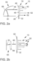
- FIG 2a a first embodiment of the method according to the invention is shown, in which the second optical reference wave field 46 is irradiated into the second irradiation surface 48, and the second irradiation surface 48 is oriented parallel to the coupling-out side 40, which serves as a common coupling-out side.
- the same wavelength is used here for the first optical reference wave field 32 and the second optical reference wave field 46.
- the optical image memory 18 transforms these into different image wave fields 52 using the different directions from which the radiation into the respective first and second radiation surfaces 28, 48 takes place.
- Figure 2b shows, in contrast, an embodiment of the method according to the invention, in which the first and second optical reference wave fields 32, 46 and additionally a third optical reference wave field 62 are generated.
- This embodiment is basically a combination of the embodiments in Figure 2a with the out Figure 1a
- the image effects 10 are realized here in the form of three different image wave fields 52. Of course, these can also be generated simultaneously or staggered.
- the same wavelength can expediently be used for the first and second optical reference wave fields 32, 46.
- a different wavelength is suitable for the third optical reference wave field 62.
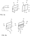
- Figure 3 two further preferred embodiments of the method according to the invention.
- Figure 3a shows the possibility of switching back and forth between different image effects 10.
- Figure 3b shows the possibility of incorporating different image effects 10 into one another and/or switching back and forth between them.
- the right part of the Figure 3a shows an example of how the first image wave field 38 is generated with the first optical reference wave field 32. This can be perceived as an image effect in the form of a substantially vertically arranged rectangle.
- the left part of the Figure 3a shows, in contrast, how the second image wave field 50 is generated with the second optical reference wave field 46. This can be perceived as an image effect in the form of a substantially horizontally arranged rectangle.
- Both image effects 10 are used with the the same optical image memory 18 is generated.
- the optical image memory 18 can, for example, have structures for transforming the optical reference wave fields 32, 46 into the respective image wave field 38, 50, which function selectively depending on the respective direction of irradiation.
- Figure 3b shows another way to switch back and forth between image effects 10, with the right part of the Figure 3b two image effects 10 can be realized with the first and second image wave fields 38, 50.
- the image effects 10 are built into one another.
- different wavelengths can be used for the first and second optical reference fields 38, 46 in order to differentiate the image effects 10 from one another, for example in terms of color.
- Figure 4 shows a lighting arrangement 70 according to the invention in two different embodiments.
- FIG 4a shown is a taillight 72 of a vehicle 14, not shown.
- a first light source 30 is arranged within the taillight 72 and is designed to generate the first optical reference wave field 32.
- the first light source 30 is arranged laterally on the optical image memory 18, which is only indicated, in front of the first irradiation surface 28. This results in the first angular offset 44 between the first irradiation surface 28 and the output side 40. In the present case, this is 90°.
- the lighting arrangement 70 also includes a second light source 74. This is designed to generate the second optical reference wave field 46.
- the second irradiation surface 48 for the second optical reference wave field 46 is arranged here parallel to the coupling-out side 40, which serves as a common coupling-out side.
- the optical image memory 18 is arranged directly behind a lens 76 of the rear light 72.
- the lateral irradiation of the first optical reference wave field 32 can be realized here starting from the first light source 30 via a light guide 78.
- Figure 5 shows an example of an image effect 80 that is made with the lighting arrangement 70 Figure 4b is produced. It can be clearly seen here how in the area of the actually clear lens 76 the first optical reference wave field 32 is generated and its transformation into the first image wave field 38 produces a horizontally extending luminous stripe pattern 82.
- the optical image memory 18 comprises, purely as an example, a diffractive optical layer. A light-emitting diode with a coherence length of 10 ⁇ m is also used purely as an example as the first light source 30.
- FIG. 6 shows a vehicle 14, which in the present case is a motor vehicle 84 according to the invention.
- the motor vehicle 84 includes at least one lighting arrangement 70 according to the invention, which is shown purely as an example in different installation positions.
- the lighting arrangement 70 can be integrated in the rear light 72 of the motor vehicle 84. But it can also be integrated in a brake light 86 of the motor vehicle 84.
- the lighting arrangement 70 can be integrated in the area of windows 88 of the motor vehicle 84. If, for example, a volume hologram is used as the optical image memory 18, it can be produced embedded directly in a disk.
- the lighting arrangement 70 can also be arranged in the area of a body part such as a sill 90 of the motor vehicle 84.
- the use of a diffractive optical layer 22 is possible.
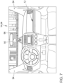
- Figure 7 shows an application example in which additional symbols 92 or lighting 94 are generated in a windshield 96 of the motor vehicle 84 using a volume hologram.
- the windshield 96 can serve as a cost-effective head-up display.
- Figure 8 shows the generation of symbols 92 with a volume hologram in a rear window 98 of the motor vehicle 84. This is purely an example of an electrically operated motor vehicle 84.
- the symbols 92 indicate a charging status of a battery of the motor vehicle 84.
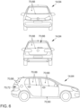
- Figure 9 shows the motor vehicle 84 Figure 8 , with an additional third brake light 100 being generated in the rear window 98.
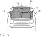
- Figure 10 shows the motor vehicle 84 from the Figures 8 and 9 , whereby the rear window 98 is used here to display entire light function groups, such as a combination of taillight 102 and brake light 104.
- the rear window 98 has the function of a flexible display.
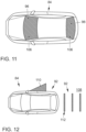
- Figure 11 shows another motor vehicle 84 according to the invention in a top view.
- the front window 96 and the rear window 98 of the motor vehicle 84 are used here to display an extended hazard warning light 106.
- Figure 12 finally shows an application in which symbols 92 are projected onto a merely indicated road surface 108 using the optical image memory 18, which in this case comprises a diffractive optical layer 22.
- the symbols 92 can represent a carpet of light 110, for example.
- the light carpet 110 can also be displayed in the form of an animation by quickly switching image effects.
Landscapes
- Engineering & Computer Science (AREA)
- Mechanical Engineering (AREA)
- General Engineering & Computer Science (AREA)
- Physics & Mathematics (AREA)
- General Physics & Mathematics (AREA)
- Chemical & Material Sciences (AREA)
- Combustion & Propulsion (AREA)
- Transportation (AREA)
- Optics & Photonics (AREA)
- Holo Graphy (AREA)
Claims (9)
- Procédé de génération d'effets d'image (10) dans l'habitacle (12) d'un véhicule (14) et/ou à l'extérieur du véhicule (14), ledit procédé comprenant au moins les étapes suivantes :- générer au moins un premier champ d'onde optique de référence (32) ;- orienter le premier champ d'onde optique de référence (32) en direction d'au moins une mémoire d'image optique (18) ;- rayonner le premier champ d'onde optique de référence (32) de manière incidente à l'au moins une surface de rayonnement incident (28) de la mémoire d'image optique (18) ;- transformer le premier champ d'onde optique de référence (32) en au moins un premier champ d'onde d'image (38) par le biais d'au moins une couche holographique (20) ou couche optique diffractive (22) de la mémoire d'image optique (18) ; et- faire sortir par couplage le premier champ d'onde d'image (38) de la couche holographique (20) ou de la couche optique diffractive (22) sur un côté de sortie par couplage (40) ;un premier décalage angulaire (44) étant prévu entre une première surface de rayonnement incident (28), par laquelle au moins le premier champ d'onde optique de référence (32) est rayonné de manière incidente, et le côté de sortie par couplage (40) par lequel au moins le premier champ d'onde d'image (38) est délivré en sortie par couplage, le champ d'onde optique de référence (32) étant dirigé dans la mémoire d'image optique (18) par réflexion sur des surfaces limites intérieures (34 ; 36) et traversant au moins par portions proportionnellement une surface limite intérieure (36) de la mémoire d'image optique (18), qui est dirigée vers la couche holographique (20) ou la couche optique diffractive (22) et qui est au moins par portions proportionnellement transparente à la lumière,au moins un premier champ d'onde optique de référence (32) et un deuxième champ d'onde optique de référence (46) étant générés et le premier champ d'onde optique de référence (32) étant rayonné dans la mémoire d'image optique (18) de manière incidente à la première surface de rayonnement incident (28) et le deuxième champ d'onde optique de référence (46) étant rayonné dans la mémoire d'image optique (18) de manière incidente à une deuxième surface de rayonnement incident (48) et les premier et deuxième champs d'onde optique de référence (46) étant transformés simultanément ou avec un retard en le premier champ d'onde d'image (38) ou en différents champs d'onde d'image (52) et le premier champ d'onde d'image (38) ou les différents champs d'onde d'image (52) étant délivré(s) en sortie par couplage sur le côté de sortie par couplage (40) qui sert de côté de sortie par couplage commun, et le premier décalage angulaire (44) étant prévu entre la première surface de rayonnement incident (28) et le côté de sortie par couplage (40) et au moins un deuxième champ d'onde optique de référence (46) étant généré qui est rayonné de manière incidente à au moins une deuxième surface de rayonnement incident (48), caractérisé en ce que la deuxième surface de rayonnement incident (48) et le côté de sortie par couplage (40), qui sert de côté de sortie par couplage commun, sont orientés parallèlement l'un à l'autre.
- Procédé selon la revendication 1, caractérisé en ce qu'un trajet de faisceau du premier champ d'onde de référence (32) et/ou du deuxième champ d'onde de référence (46) est influencé par le biais d'un réflecteur (66) et/ou d'une optique de collimation (68) et/ou d'un guide de lumière (78).
- Procédé selon l'une des revendications précédentes, caractérisé en ce que la mémoire d'image optique (18) comprend au moins une première couche de substrat (26) qui présente la première surface de rayonnement incident (28) et une deuxième surface de rayonnement incident (48).
- Ensemble d'éclairage (70) destiné à un véhicule (84), ledit ensemble d'éclairage comprenant au moins :- une première source de lumière (30) destinée à générer au moins un premier champ d'onde optique de référence (32) ;- une mémoire d'image optique (18) comportant au moins une première surface de rayonnement incident (28), au moins une couche holographique (20) ou une couche optique diffractive (22) et un côté de sortie par couplage (40) ;- des moyens techniques (64) destinés à diriger le premier champ d'onde optique de référence (32) en direction de la mémoire d'image optique (18) ;- un premier décalage angulaire (44) étant prévu entre la première surface de rayonnement incident (28) et le côté de sortie par couplage (40),la mémoire d'image optique (18) étant conçue pour diriger le champ d'onde optique de référence (32) par réflexion sur des surfaces limites intérieures (34 ; 36) et une surface limite intérieure (36) de la mémoire d'image optique (18), qui est dirigée vers la couche holographique (20) ou la couche optique diffractive (22), étant au moins par portions proportionnellement transparente à la lumière,l'ensemble d'éclairage (70) comprenant au moins une deuxième source de lumière (74) destinée à générer au moins un deuxième champ d'onde optique de référence (46) ou la première source de lumière (30) étant conçue à cet effet et la mémoire d'image optique (18) comportant en outre une deuxième surface de rayonnement incident (48) et étant conçue pour transformer les premier et deuxième champs d'onde optique de référence (32 ; 46) en le premier champ d'onde d'image (38) ou en différents champs d'onde d'image (52), et le premier décalage angulaire (44) étant prévu entre la première surface de rayonnement incident (28) et le côté de sortie par couplage (40) et caractérisé en ce que la mémoire d'image optique (18) comporte une deuxième surface de rayonnement incident (48) qui est orientée parallèlement au côté de sortie par couplage (40) qui sert de côté de sortie par couplage commun.
- Ensemble d'éclairage (70) selon la revendication 4, caractérisé en ce qu'il comprend un réflecteur (66) destiné à dévier le deuxième champ d'onde de référence (46) et/ou une optique de collimation (68) destinée à redresser le deuxième champ d'onde de référence (46).
- Ensemble d'éclairage (70) selon l'une des revendications 4 à 5, caractérisé en ce qu'il comprend un guide de lumière (78) destiné à diriger le premier champ d'ondes de référence (32) en direction de la première surface de rayonnement incident (28).
- Ensemble d'éclairage (70) selon l'une des revendications 4 à 6, caractérisé en ce que la mémoire optique d'image (18) comprend au moins une première couche de substrat (26) qui comporte la première surface de rayonnement incident (28) et une deuxième surface de rayonnement incident (48).
- Ensemble d'éclairage (70) selon l'une des revendications 4 à 7, caractérisé en ce que la mémoire optique d'image (18) comprend au moins une première couche de substrat (26) qui comporte la première surface de rayonnement incident (28) et une deuxième surface de rayonnement incident (48), et comprend en outre une deuxième couche de substrat (56), la couche holographique (20) ou couche optique diffractive (22) étant disposée entre les première et deuxième couches de substrat (26 ; 56).
- Véhicule automobile, comprenant au moins un ensemble d'éclairage (70) destiné à un véhicule (84) selon l'une des revendications 4 à 8.
Applications Claiming Priority (2)
| Application Number | Priority Date | Filing Date | Title |
|---|---|---|---|
| DE102016217398.7A DE102016217398A1 (de) | 2016-09-13 | 2016-09-13 | Verfahren und Vorrichtung zur Erzeugung von Bildeffekten im Innenraum oder außerhalb eines Fahrzeugs |
| PCT/EP2017/070013 WO2018050362A1 (fr) | 2016-09-13 | 2017-08-08 | Procédé et dispositif de production d'effets d'image dans l'habitacle ou à l'extérieur d'un véhicule |
Publications (2)
| Publication Number | Publication Date |
|---|---|
| EP3513253A1 EP3513253A1 (fr) | 2019-07-24 |
| EP3513253B1 true EP3513253B1 (fr) | 2024-03-13 |
Family
ID=59677208
Family Applications (1)
| Application Number | Title | Priority Date | Filing Date |
|---|---|---|---|
| EP17754658.7A Active EP3513253B1 (fr) | 2016-09-13 | 2017-08-08 | Procede et dispositif de production d'effets d'image dans l'habitacle ou a l'exterieur d'un vehicule |
Country Status (5)
| Country | Link |
|---|---|
| US (1) | US11347184B2 (fr) |
| EP (1) | EP3513253B1 (fr) |
| CN (1) | CN109716243A (fr) |
| DE (1) | DE102016217398A1 (fr) |
| WO (1) | WO2018050362A1 (fr) |
Families Citing this family (12)
| Publication number | Priority date | Publication date | Assignee | Title |
|---|---|---|---|---|
| CN110895389B (zh) * | 2018-09-10 | 2021-08-24 | 英属开曼群岛商音飞光电科技股份有限公司 | 全像影像片体、全像影像记录方法与重建方法 |
| KR102619559B1 (ko) * | 2018-11-16 | 2023-12-29 | 현대모비스 주식회사 | 자율주행 차량의 라이팅장치 |
| TWI764063B (zh) * | 2019-11-13 | 2022-05-11 | 揚明光學股份有限公司 | 迎賓燈 |
| EP4112387A4 (fr) * | 2020-02-28 | 2023-08-16 | Sony Group Corporation | Dispositif de traitement d'image, système d'affichage, procédé de traitement d'image et support d'enregistrement |
| CN111352248A (zh) * | 2020-04-17 | 2020-06-30 | 深圳铅笔视界科技有限公司 | 抬头显示系统 |
| GB2609762B (en) * | 2020-05-21 | 2023-08-30 | Jaguar Land Rover Ltd | Illumination device, method and system |
| GB2595452B (en) * | 2020-05-21 | 2022-10-26 | Jaguar Land Rover Ltd | Illumination device, method and system |
| DE102021207573A1 (de) | 2021-02-01 | 2022-08-04 | Carl Zeiss Jena Gmbh | Holographische einstiegsleuchte in einem türrahmen |
| DE102021104643A1 (de) | 2021-02-26 | 2022-09-01 | HELLA GmbH & Co. KGaA | Beleuchtungsvorrichtung für einen Türeinstieg |
| DE102021111743B4 (de) | 2021-05-06 | 2025-11-06 | Dr. Ing. H.C. F. Porsche Aktiengesellschaft | Verfahren zum Anzeigen eines dreidimensionalen Hologramms |
| CN115388380B (zh) * | 2021-05-19 | 2026-01-09 | 宁波舜宇车载光学技术有限公司 | 复合透镜、投影系统及其制造方法 |
| US12235608B2 (en) | 2023-02-23 | 2025-02-25 | Ford Global Technologies, Llc | Smart vehicle holograms |
Citations (2)
| Publication number | Priority date | Publication date | Assignee | Title |
|---|---|---|---|---|
| JPH03121942A (ja) * | 1989-10-04 | 1991-05-23 | Nissan Motor Co Ltd | 車両用表示器 |
| US5106174A (en) * | 1990-04-16 | 1992-04-21 | Hughes Aircraft Company | Ideal distribution CHMSL hologram with double exposure technique |
Family Cites Families (20)
| Publication number | Priority date | Publication date | Assignee | Title |
|---|---|---|---|---|
| US4790613A (en) * | 1987-01-06 | 1988-12-13 | Hughes Aircraft Company | Holographic display panel for a vehicle windshield |
| US4892369A (en) * | 1987-01-06 | 1990-01-09 | Hughes Aircraft Company | Holographic rear window stoplight |
| US4916593A (en) | 1989-01-04 | 1990-04-10 | Hughes Aircraft Company | Remotely illuminated transparent holographic stoplight for automobiles |
| JP2808780B2 (ja) | 1990-01-30 | 1998-10-08 | 日産自動車株式会社 | 車両用灯具 |
| US5186533A (en) | 1990-01-30 | 1993-02-16 | Nissan Motor Co., Ltd. | Lamp arrangement for motor vehicle |
| JP3768542B2 (ja) * | 1992-06-09 | 2006-04-19 | 株式会社デンソー | 表示装置 |
| DE4411440A1 (de) | 1993-03-31 | 1994-10-06 | Koito Mfg Co Ltd | Holographische, hochangebrachte Bremsleuchte für Fahrzeuge |
| JP3544010B2 (ja) * | 1994-10-25 | 2004-07-21 | 本田技研工業株式会社 | 車両用灯火器 |
| US5729367A (en) * | 1996-10-02 | 1998-03-17 | Hughes Electronics | Multiple-image multiplexed holographic display |
| WO1999042758A1 (fr) * | 1998-02-20 | 1999-08-26 | Nippon Zeon Co., Ltd. | Equipement d'eclairage |
| DE20001311U1 (de) | 2000-01-26 | 2000-04-13 | Münch, Enrico, 81925 München | Warnvorrichtung für Fahrzeuge, insbesondere Kfz |
| DE10157028A1 (de) | 2001-11-21 | 2003-06-05 | Bosch Gmbh Robert | Sensoreinrichtung, insbesondere zur Steuerung von Beleuchtungseinrichtungen eines Kraftfahrzeugs |
| EP1649309A4 (fr) * | 2003-07-03 | 2011-03-09 | Holo Touch Inc | Interfaces homme-machine holographiques |
| DE102006050548B4 (de) | 2006-10-26 | 2014-05-08 | Bayerische Motoren Werke Aktiengesellschaft | Verfahren zur Warnung anderer Verkehrsteilnehmer |
| WO2009059123A2 (fr) | 2007-11-02 | 2009-05-07 | Netter Jessica D | Système de distribution de contenu visuel à un dispositif d'affichage ciblé |
| FR2954923B1 (fr) * | 2010-01-06 | 2012-05-04 | Delphi Tech Inc | Dispositif diffractif de signalisation pour retroviseur avec affichage 2d/3d |
| DE102011012520A1 (de) | 2011-02-26 | 2012-08-30 | GM Global Technology Operations LLC (n. d. Ges. d. Staates Delaware) | Dritte Bremsleuchte für ein Kraftfahrzeug und Verfahren zum Betreiben einer dritten Bremsleuchte für ein Kraftfahrzeug |
| DE102014210213A1 (de) | 2013-06-20 | 2014-12-24 | Volkswagen Aktiengesellschaft | Verfahren und Vorrichtung zum Steuern einer Lichtemission einer Heckleuchte eines Fahrzeugs |
| DE202013008540U1 (de) | 2013-09-26 | 2015-01-09 | Automotive Lighting Reutlingen Gmbh | Beleuchtungseinrichtung für Fahrzeuge |
| DE202014003241U1 (de) | 2014-04-15 | 2015-07-20 | GM Global Technology Operations LLC (n. d. Ges. d. Staates Delaware) | Holographische Anzeigevorrichtung, Fahrzeug mit holographischer Anzeigevorrichtung und Computerprogrammprodukt |
-
2016
- 2016-09-13 DE DE102016217398.7A patent/DE102016217398A1/de active Pending
-
2017
- 2017-08-08 US US16/332,096 patent/US11347184B2/en active Active
- 2017-08-08 CN CN201780056230.1A patent/CN109716243A/zh active Pending
- 2017-08-08 EP EP17754658.7A patent/EP3513253B1/fr active Active
- 2017-08-08 WO PCT/EP2017/070013 patent/WO2018050362A1/fr not_active Ceased
Patent Citations (2)
| Publication number | Priority date | Publication date | Assignee | Title |
|---|---|---|---|---|
| JPH03121942A (ja) * | 1989-10-04 | 1991-05-23 | Nissan Motor Co Ltd | 車両用表示器 |
| US5106174A (en) * | 1990-04-16 | 1992-04-21 | Hughes Aircraft Company | Ideal distribution CHMSL hologram with double exposure technique |
Also Published As
| Publication number | Publication date |
|---|---|
| DE102016217398A1 (de) | 2018-03-15 |
| US11347184B2 (en) | 2022-05-31 |
| WO2018050362A1 (fr) | 2018-03-22 |
| US20200183328A1 (en) | 2020-06-11 |
| CN109716243A (zh) | 2019-05-03 |
| EP3513253A1 (fr) | 2019-07-24 |
Similar Documents
| Publication | Publication Date | Title |
|---|---|---|
| EP3513253B1 (fr) | Procede et dispositif de production d'effets d'image dans l'habitacle ou a l'exterieur d'un vehicule | |
| DE102015102243B4 (de) | Beleuchtungsvorrichtung für Fahrzeuge | |
| EP3237795B1 (fr) | Dispositif d'éclairage pour véhicules | |
| DE102015115128B4 (de) | Beleuchtungsvorrichtung für Fahrzeuge | |
| DE102014117842A1 (de) | Zusatzbremsleuchte für Fahrzeuge | |
| WO2018054985A1 (fr) | Dispositif d'éclairage pour véhicules | |
| EP3814816B1 (fr) | Dispositif d'éclairage de véhicules | |
| DE202014003241U1 (de) | Holographische Anzeigevorrichtung, Fahrzeug mit holographischer Anzeigevorrichtung und Computerprogrammprodukt | |
| DE102013108333A1 (de) | Beleuchtungsvorrichtung für Fahrzeuge | |
| WO2023088716A1 (fr) | Élément de guidage de lumière pour un dispositif d'éclairage pour un véhicule automobile | |
| WO2004001482A1 (fr) | Systeme d'affichage holographique | |
| DE102011012520A1 (de) | Dritte Bremsleuchte für ein Kraftfahrzeug und Verfahren zum Betreiben einer dritten Bremsleuchte für ein Kraftfahrzeug | |
| DE102022100796A1 (de) | Beleuchtungsvorrichtung für den Innenraum eines Kraftfahrzeugs | |
| EP4113001B1 (fr) | Module d'éclairage pour dispositif d'éclairage d'un véhicule et procédé de réduction d'une désaturation de la couleur dans un module d'éclairage pour un dispositif d'éclairage d'un véhicule | |
| DE102016217402B4 (de) | Verfahren und Beleuchtungsanordnung, sowie Kraftfahrzeug umfassend eine Beleuchtungsanordnung zur Erzeugung von Bildeffekten | |
| WO2025031998A1 (fr) | Dispositif d'éclairage et lampe de véhicule automobile | |
| DE102022106488B3 (de) | Anzeigevorrichtung für ein Fahrzeug | |
| DE102012213547B4 (de) | Beleuchtungseinrichtung für ein Kraftfahrzeug | |
| DE102015201936A1 (de) | Holografische Anzeigevorrichtung | |
| DE102014118378A1 (de) | Beleuchtungsvorrichtung für Fahrzeuge | |
| EP4436815A1 (fr) | Dispositif d'affichage pour passager de véhicule et procédé de fonctionnement associé | |
| DE102022132906A1 (de) | Beleuchtungsvorrichtung für ein Kraftfahrzeug | |
| DE102015200339B4 (de) | Kraftfahrzeug mit einer Windschutzsscheibe und wenigstens einem beleuchtbaren Bedienelement im Innenraum | |
| DE202020005582U1 (de) | Beleuchtungseinrichtung für Fahrzeuge | |
| DE102023103962A1 (de) | Vorrichtung zur Erzeugung einer polychromatischen holographischen Abbildung in einer Sitzblende |
Legal Events
| Date | Code | Title | Description |
|---|---|---|---|
| STAA | Information on the status of an ep patent application or granted ep patent |
Free format text: STATUS: UNKNOWN |
|
| STAA | Information on the status of an ep patent application or granted ep patent |
Free format text: STATUS: THE INTERNATIONAL PUBLICATION HAS BEEN MADE |
|
| PUAI | Public reference made under article 153(3) epc to a published international application that has entered the european phase |
Free format text: ORIGINAL CODE: 0009012 |
|
| STAA | Information on the status of an ep patent application or granted ep patent |
Free format text: STATUS: REQUEST FOR EXAMINATION WAS MADE |
|
| 17P | Request for examination filed |
Effective date: 20190415 |
|
| AK | Designated contracting states |
Kind code of ref document: A1 Designated state(s): AL AT BE BG CH CY CZ DE DK EE ES FI FR GB GR HR HU IE IS IT LI LT LU LV MC MK MT NL NO PL PT RO RS SE SI SK SM TR |
|
| AX | Request for extension of the european patent |
Extension state: BA ME |
|
| DAV | Request for validation of the european patent (deleted) | ||
| DAX | Request for extension of the european patent (deleted) | ||
| STAA | Information on the status of an ep patent application or granted ep patent |
Free format text: STATUS: EXAMINATION IS IN PROGRESS |
|
| 17Q | First examination report despatched |
Effective date: 20210507 |
|
| GRAP | Despatch of communication of intention to grant a patent |
Free format text: ORIGINAL CODE: EPIDOSNIGR1 |
|
| STAA | Information on the status of an ep patent application or granted ep patent |
Free format text: STATUS: GRANT OF PATENT IS INTENDED |
|
| RIC1 | Information provided on ipc code assigned before grant |
Ipc: B60Q 1/30 20060101ALI20230925BHEP Ipc: B60Q 1/50 20060101ALI20230925BHEP Ipc: F21S 43/20 20180101ALI20230925BHEP Ipc: F21S 43/251 20180101ALI20230925BHEP Ipc: B60Q 1/26 20060101ALI20230925BHEP Ipc: B60Q 1/00 20060101ALI20230925BHEP Ipc: B60K 35/00 20060101ALI20230925BHEP Ipc: G03H 1/26 20060101ALI20230925BHEP Ipc: G02B 27/42 20060101ALI20230925BHEP Ipc: G02B 27/01 20060101ALI20230925BHEP Ipc: G03H 1/22 20060101AFI20230925BHEP |
|
| INTG | Intention to grant announced |
Effective date: 20231020 |
|
| P01 | Opt-out of the competence of the unified patent court (upc) registered |
Effective date: 20231215 |
|
| GRAS | Grant fee paid |
Free format text: ORIGINAL CODE: EPIDOSNIGR3 |
|
| GRAA | (expected) grant |
Free format text: ORIGINAL CODE: 0009210 |
|
| STAA | Information on the status of an ep patent application or granted ep patent |
Free format text: STATUS: THE PATENT HAS BEEN GRANTED |
|
| AK | Designated contracting states |
Kind code of ref document: B1 Designated state(s): AL AT BE BG CH CY CZ DE DK EE ES FI FR GB GR HR HU IE IS IT LI LT LU LV MC MK MT NL NO PL PT RO RS SE SI SK SM TR |
|
| REG | Reference to a national code |
Ref country code: GB Ref legal event code: FG4D Free format text: NOT ENGLISH |
|
| REG | Reference to a national code |
Ref country code: CH Ref legal event code: EP |
|
| REG | Reference to a national code |
Ref country code: DE Ref legal event code: R096 Ref document number: 502017015926 Country of ref document: DE |
|
| REG | Reference to a national code |
Ref country code: IE Ref legal event code: FG4D Free format text: LANGUAGE OF EP DOCUMENT: GERMAN |
|
| PG25 | Lapsed in a contracting state [announced via postgrant information from national office to epo] |
Ref country code: LT Free format text: LAPSE BECAUSE OF FAILURE TO SUBMIT A TRANSLATION OF THE DESCRIPTION OR TO PAY THE FEE WITHIN THE PRESCRIBED TIME-LIMIT Effective date: 20240313 |
|
| REG | Reference to a national code |
Ref country code: LT Ref legal event code: MG9D |
|
| PG25 | Lapsed in a contracting state [announced via postgrant information from national office to epo] |
Ref country code: GR Free format text: LAPSE BECAUSE OF FAILURE TO SUBMIT A TRANSLATION OF THE DESCRIPTION OR TO PAY THE FEE WITHIN THE PRESCRIBED TIME-LIMIT Effective date: 20240614 |
|
| REG | Reference to a national code |
Ref country code: NL Ref legal event code: MP Effective date: 20240313 |
|
| PG25 | Lapsed in a contracting state [announced via postgrant information from national office to epo] |
Ref country code: HR Free format text: LAPSE BECAUSE OF FAILURE TO SUBMIT A TRANSLATION OF THE DESCRIPTION OR TO PAY THE FEE WITHIN THE PRESCRIBED TIME-LIMIT Effective date: 20240313 Ref country code: RS Free format text: LAPSE BECAUSE OF FAILURE TO SUBMIT A TRANSLATION OF THE DESCRIPTION OR TO PAY THE FEE WITHIN THE PRESCRIBED TIME-LIMIT Effective date: 20240613 |
|
| PG25 | Lapsed in a contracting state [announced via postgrant information from national office to epo] |
Ref country code: ES Free format text: LAPSE BECAUSE OF FAILURE TO SUBMIT A TRANSLATION OF THE DESCRIPTION OR TO PAY THE FEE WITHIN THE PRESCRIBED TIME-LIMIT Effective date: 20240313 |
|
| PG25 | Lapsed in a contracting state [announced via postgrant information from national office to epo] |
Ref country code: RS Free format text: LAPSE BECAUSE OF FAILURE TO SUBMIT A TRANSLATION OF THE DESCRIPTION OR TO PAY THE FEE WITHIN THE PRESCRIBED TIME-LIMIT Effective date: 20240613 Ref country code: NO Free format text: LAPSE BECAUSE OF FAILURE TO SUBMIT A TRANSLATION OF THE DESCRIPTION OR TO PAY THE FEE WITHIN THE PRESCRIBED TIME-LIMIT Effective date: 20240613 Ref country code: LT Free format text: LAPSE BECAUSE OF FAILURE TO SUBMIT A TRANSLATION OF THE DESCRIPTION OR TO PAY THE FEE WITHIN THE PRESCRIBED TIME-LIMIT Effective date: 20240313 Ref country code: HR Free format text: LAPSE BECAUSE OF FAILURE TO SUBMIT A TRANSLATION OF THE DESCRIPTION OR TO PAY THE FEE WITHIN THE PRESCRIBED TIME-LIMIT Effective date: 20240313 Ref country code: GR Free format text: LAPSE BECAUSE OF FAILURE TO SUBMIT A TRANSLATION OF THE DESCRIPTION OR TO PAY THE FEE WITHIN THE PRESCRIBED TIME-LIMIT Effective date: 20240614 Ref country code: FI Free format text: LAPSE BECAUSE OF FAILURE TO SUBMIT A TRANSLATION OF THE DESCRIPTION OR TO PAY THE FEE WITHIN THE PRESCRIBED TIME-LIMIT Effective date: 20240313 Ref country code: ES Free format text: LAPSE BECAUSE OF FAILURE TO SUBMIT A TRANSLATION OF THE DESCRIPTION OR TO PAY THE FEE WITHIN THE PRESCRIBED TIME-LIMIT Effective date: 20240313 Ref country code: BG Free format text: LAPSE BECAUSE OF FAILURE TO SUBMIT A TRANSLATION OF THE DESCRIPTION OR TO PAY THE FEE WITHIN THE PRESCRIBED TIME-LIMIT Effective date: 20240313 |
|
| PG25 | Lapsed in a contracting state [announced via postgrant information from national office to epo] |
Ref country code: SE Free format text: LAPSE BECAUSE OF FAILURE TO SUBMIT A TRANSLATION OF THE DESCRIPTION OR TO PAY THE FEE WITHIN THE PRESCRIBED TIME-LIMIT Effective date: 20240313 Ref country code: LV Free format text: LAPSE BECAUSE OF FAILURE TO SUBMIT A TRANSLATION OF THE DESCRIPTION OR TO PAY THE FEE WITHIN THE PRESCRIBED TIME-LIMIT Effective date: 20240313 |
|
| PG25 | Lapsed in a contracting state [announced via postgrant information from national office to epo] |
Ref country code: NL Free format text: LAPSE BECAUSE OF FAILURE TO SUBMIT A TRANSLATION OF THE DESCRIPTION OR TO PAY THE FEE WITHIN THE PRESCRIBED TIME-LIMIT Effective date: 20240313 |
|
| PG25 | Lapsed in a contracting state [announced via postgrant information from national office to epo] |
Ref country code: NL Free format text: LAPSE BECAUSE OF FAILURE TO SUBMIT A TRANSLATION OF THE DESCRIPTION OR TO PAY THE FEE WITHIN THE PRESCRIBED TIME-LIMIT Effective date: 20240313 |
|
| PG25 | Lapsed in a contracting state [announced via postgrant information from national office to epo] |
Ref country code: IS Free format text: LAPSE BECAUSE OF FAILURE TO SUBMIT A TRANSLATION OF THE DESCRIPTION OR TO PAY THE FEE WITHIN THE PRESCRIBED TIME-LIMIT Effective date: 20240713 |
|
| PG25 | Lapsed in a contracting state [announced via postgrant information from national office to epo] |
Ref country code: PT Free format text: LAPSE BECAUSE OF FAILURE TO SUBMIT A TRANSLATION OF THE DESCRIPTION OR TO PAY THE FEE WITHIN THE PRESCRIBED TIME-LIMIT Effective date: 20240715 Ref country code: SM Free format text: LAPSE BECAUSE OF FAILURE TO SUBMIT A TRANSLATION OF THE DESCRIPTION OR TO PAY THE FEE WITHIN THE PRESCRIBED TIME-LIMIT Effective date: 20240313 |
|
| PG25 | Lapsed in a contracting state [announced via postgrant information from national office to epo] |
Ref country code: CZ Free format text: LAPSE BECAUSE OF FAILURE TO SUBMIT A TRANSLATION OF THE DESCRIPTION OR TO PAY THE FEE WITHIN THE PRESCRIBED TIME-LIMIT Effective date: 20240313 Ref country code: EE Free format text: LAPSE BECAUSE OF FAILURE TO SUBMIT A TRANSLATION OF THE DESCRIPTION OR TO PAY THE FEE WITHIN THE PRESCRIBED TIME-LIMIT Effective date: 20240313 |
|
| PG25 | Lapsed in a contracting state [announced via postgrant information from national office to epo] |
Ref country code: PL Free format text: LAPSE BECAUSE OF FAILURE TO SUBMIT A TRANSLATION OF THE DESCRIPTION OR TO PAY THE FEE WITHIN THE PRESCRIBED TIME-LIMIT Effective date: 20240313 |
|
| PG25 | Lapsed in a contracting state [announced via postgrant information from national office to epo] |
Ref country code: SK Free format text: LAPSE BECAUSE OF FAILURE TO SUBMIT A TRANSLATION OF THE DESCRIPTION OR TO PAY THE FEE WITHIN THE PRESCRIBED TIME-LIMIT Effective date: 20240313 |
|
| PG25 | Lapsed in a contracting state [announced via postgrant information from national office to epo] |
Ref country code: SM Free format text: LAPSE BECAUSE OF FAILURE TO SUBMIT A TRANSLATION OF THE DESCRIPTION OR TO PAY THE FEE WITHIN THE PRESCRIBED TIME-LIMIT Effective date: 20240313 Ref country code: SK Free format text: LAPSE BECAUSE OF FAILURE TO SUBMIT A TRANSLATION OF THE DESCRIPTION OR TO PAY THE FEE WITHIN THE PRESCRIBED TIME-LIMIT Effective date: 20240313 Ref country code: RO Free format text: LAPSE BECAUSE OF FAILURE TO SUBMIT A TRANSLATION OF THE DESCRIPTION OR TO PAY THE FEE WITHIN THE PRESCRIBED TIME-LIMIT Effective date: 20240313 Ref country code: PT Free format text: LAPSE BECAUSE OF FAILURE TO SUBMIT A TRANSLATION OF THE DESCRIPTION OR TO PAY THE FEE WITHIN THE PRESCRIBED TIME-LIMIT Effective date: 20240715 Ref country code: PL Free format text: LAPSE BECAUSE OF FAILURE TO SUBMIT A TRANSLATION OF THE DESCRIPTION OR TO PAY THE FEE WITHIN THE PRESCRIBED TIME-LIMIT Effective date: 20240313 Ref country code: IS Free format text: LAPSE BECAUSE OF FAILURE TO SUBMIT A TRANSLATION OF THE DESCRIPTION OR TO PAY THE FEE WITHIN THE PRESCRIBED TIME-LIMIT Effective date: 20240713 Ref country code: EE Free format text: LAPSE BECAUSE OF FAILURE TO SUBMIT A TRANSLATION OF THE DESCRIPTION OR TO PAY THE FEE WITHIN THE PRESCRIBED TIME-LIMIT Effective date: 20240313 Ref country code: CZ Free format text: LAPSE BECAUSE OF FAILURE TO SUBMIT A TRANSLATION OF THE DESCRIPTION OR TO PAY THE FEE WITHIN THE PRESCRIBED TIME-LIMIT Effective date: 20240313 |
|
| PG25 | Lapsed in a contracting state [announced via postgrant information from national office to epo] |
Ref country code: IT Free format text: LAPSE BECAUSE OF FAILURE TO SUBMIT A TRANSLATION OF THE DESCRIPTION OR TO PAY THE FEE WITHIN THE PRESCRIBED TIME-LIMIT Effective date: 20240313 |
|
| REG | Reference to a national code |
Ref country code: DE Ref legal event code: R097 Ref document number: 502017015926 Country of ref document: DE |
|
| PG25 | Lapsed in a contracting state [announced via postgrant information from national office to epo] |
Ref country code: IT Free format text: LAPSE BECAUSE OF FAILURE TO SUBMIT A TRANSLATION OF THE DESCRIPTION OR TO PAY THE FEE WITHIN THE PRESCRIBED TIME-LIMIT Effective date: 20240313 |
|
| PG25 | Lapsed in a contracting state [announced via postgrant information from national office to epo] |
Ref country code: DK Free format text: LAPSE BECAUSE OF FAILURE TO SUBMIT A TRANSLATION OF THE DESCRIPTION OR TO PAY THE FEE WITHIN THE PRESCRIBED TIME-LIMIT Effective date: 20240313 |
|
| PLBE | No opposition filed within time limit |
Free format text: ORIGINAL CODE: 0009261 |
|
| STAA | Information on the status of an ep patent application or granted ep patent |
Free format text: STATUS: NO OPPOSITION FILED WITHIN TIME LIMIT |
|
| PG25 | Lapsed in a contracting state [announced via postgrant information from national office to epo] |
Ref country code: DK Free format text: LAPSE BECAUSE OF FAILURE TO SUBMIT A TRANSLATION OF THE DESCRIPTION OR TO PAY THE FEE WITHIN THE PRESCRIBED TIME-LIMIT Effective date: 20240313 |
|
| 26N | No opposition filed |
Effective date: 20241216 |
|
| REG | Reference to a national code |
Ref country code: CH Ref legal event code: PL |
|
| PG25 | Lapsed in a contracting state [announced via postgrant information from national office to epo] |
Ref country code: LU Free format text: LAPSE BECAUSE OF NON-PAYMENT OF DUE FEES Effective date: 20240808 |
|
| PG25 | Lapsed in a contracting state [announced via postgrant information from national office to epo] |
Ref country code: CH Free format text: LAPSE BECAUSE OF NON-PAYMENT OF DUE FEES Effective date: 20240831 Ref country code: SI Free format text: LAPSE BECAUSE OF FAILURE TO SUBMIT A TRANSLATION OF THE DESCRIPTION OR TO PAY THE FEE WITHIN THE PRESCRIBED TIME-LIMIT Effective date: 20240313 Ref country code: MC Free format text: LAPSE BECAUSE OF FAILURE TO SUBMIT A TRANSLATION OF THE DESCRIPTION OR TO PAY THE FEE WITHIN THE PRESCRIBED TIME-LIMIT Effective date: 20240313 |
|
| REG | Reference to a national code |
Ref country code: BE Ref legal event code: MM Effective date: 20240831 |
|
| PG25 | Lapsed in a contracting state [announced via postgrant information from national office to epo] |
Ref country code: BE Free format text: LAPSE BECAUSE OF NON-PAYMENT OF DUE FEES Effective date: 20240831 |
|
| PG25 | Lapsed in a contracting state [announced via postgrant information from national office to epo] |
Ref country code: IE Free format text: LAPSE BECAUSE OF NON-PAYMENT OF DUE FEES Effective date: 20240808 |
|
| PGFP | Annual fee paid to national office [announced via postgrant information from national office to epo] |
Ref country code: DE Payment date: 20250831 Year of fee payment: 9 |
|
| REG | Reference to a national code |
Ref country code: AT Ref legal event code: MM01 Ref document number: 1666328 Country of ref document: AT Kind code of ref document: T Effective date: 20240808 |
|
| PGFP | Annual fee paid to national office [announced via postgrant information from national office to epo] |
Ref country code: GB Payment date: 20250826 Year of fee payment: 9 |
|
| PG25 | Lapsed in a contracting state [announced via postgrant information from national office to epo] |
Ref country code: AT Free format text: LAPSE BECAUSE OF NON-PAYMENT OF DUE FEES Effective date: 20240808 |
|
| PGFP | Annual fee paid to national office [announced via postgrant information from national office to epo] |
Ref country code: FR Payment date: 20250825 Year of fee payment: 9 |
|
| PG25 | Lapsed in a contracting state [announced via postgrant information from national office to epo] |
Ref country code: CY Free format text: LAPSE BECAUSE OF FAILURE TO SUBMIT A TRANSLATION OF THE DESCRIPTION OR TO PAY THE FEE WITHIN THE PRESCRIBED TIME-LIMIT; INVALID AB INITIO Effective date: 20170808 |
|
| PG25 | Lapsed in a contracting state [announced via postgrant information from national office to epo] |
Ref country code: HU Free format text: LAPSE BECAUSE OF FAILURE TO SUBMIT A TRANSLATION OF THE DESCRIPTION OR TO PAY THE FEE WITHIN THE PRESCRIBED TIME-LIMIT; INVALID AB INITIO Effective date: 20170808 |