EP3814816B1 - Dispositif d'éclairage de véhicules - Google Patents
Dispositif d'éclairage de véhicules Download PDFInfo
- Publication number
- EP3814816B1 EP3814816B1 EP19735265.1A EP19735265A EP3814816B1 EP 3814816 B1 EP3814816 B1 EP 3814816B1 EP 19735265 A EP19735265 A EP 19735265A EP 3814816 B1 EP3814816 B1 EP 3814816B1
- Authority
- EP
- European Patent Office
- Prior art keywords
- hologram
- light
- lighting device
- primary
- coupling
- Prior art date
- Legal status (The legal status is an assumption and is not a legal conclusion. Google has not performed a legal analysis and makes no representation as to the accuracy of the status listed.)
- Active
Links
Images





Classifications
-
- F—MECHANICAL ENGINEERING; LIGHTING; HEATING; WEAPONS; BLASTING
- F21—LIGHTING
- F21S—NON-PORTABLE LIGHTING DEVICES; SYSTEMS THEREOF; VEHICLE LIGHTING DEVICES SPECIALLY ADAPTED FOR VEHICLE EXTERIORS
- F21S43/00—Signalling devices specially adapted for vehicle exteriors, e.g. brake lamps, direction indicator lights or reversing lights
- F21S43/20—Signalling devices specially adapted for vehicle exteriors, e.g. brake lamps, direction indicator lights or reversing lights characterised by refractors, transparent cover plates, light guides or filters
- F21S43/2605—Refractors
-
- G—PHYSICS
- G02—OPTICS
- G02B—OPTICAL ELEMENTS, SYSTEMS OR APPARATUS
- G02B5/00—Optical elements other than lenses
- G02B5/18—Diffraction gratings
- G02B5/1828—Diffraction gratings having means for producing variable diffraction
-
- F—MECHANICAL ENGINEERING; LIGHTING; HEATING; WEAPONS; BLASTING
- F21—LIGHTING
- F21S—NON-PORTABLE LIGHTING DEVICES; SYSTEMS THEREOF; VEHICLE LIGHTING DEVICES SPECIALLY ADAPTED FOR VEHICLE EXTERIORS
- F21S43/00—Signalling devices specially adapted for vehicle exteriors, e.g. brake lamps, direction indicator lights or reversing lights
- F21S43/10—Signalling devices specially adapted for vehicle exteriors, e.g. brake lamps, direction indicator lights or reversing lights characterised by the light source
- F21S43/13—Signalling devices specially adapted for vehicle exteriors, e.g. brake lamps, direction indicator lights or reversing lights characterised by the light source characterised by the type of light source
- F21S43/14—Light emitting diodes [LED]
-
- F—MECHANICAL ENGINEERING; LIGHTING; HEATING; WEAPONS; BLASTING
- F21—LIGHTING
- F21S—NON-PORTABLE LIGHTING DEVICES; SYSTEMS THEREOF; VEHICLE LIGHTING DEVICES SPECIALLY ADAPTED FOR VEHICLE EXTERIORS
- F21S43/00—Signalling devices specially adapted for vehicle exteriors, e.g. brake lamps, direction indicator lights or reversing lights
- F21S43/20—Signalling devices specially adapted for vehicle exteriors, e.g. brake lamps, direction indicator lights or reversing lights characterised by refractors, transparent cover plates, light guides or filters
- F21S43/235—Light guides
-
- F—MECHANICAL ENGINEERING; LIGHTING; HEATING; WEAPONS; BLASTING
- F21—LIGHTING
- F21S—NON-PORTABLE LIGHTING DEVICES; SYSTEMS THEREOF; VEHICLE LIGHTING DEVICES SPECIALLY ADAPTED FOR VEHICLE EXTERIORS
- F21S43/00—Signalling devices specially adapted for vehicle exteriors, e.g. brake lamps, direction indicator lights or reversing lights
- F21S43/20—Signalling devices specially adapted for vehicle exteriors, e.g. brake lamps, direction indicator lights or reversing lights characterised by refractors, transparent cover plates, light guides or filters
- F21S43/26—Refractors, transparent cover plates, light guides or filters not provided in groups F21S43/235 - F21S43/255
-
- G—PHYSICS
- G02—OPTICS
- G02B—OPTICAL ELEMENTS, SYSTEMS OR APPARATUS
- G02B27/00—Optical systems or apparatus not provided for by any of the groups G02B1/00 - G02B26/00, G02B30/00
- G02B27/42—Diffraction optics, i.e. systems including a diffractive element being designed for providing a diffractive effect
- G02B27/4272—Diffraction optics, i.e. systems including a diffractive element being designed for providing a diffractive effect having plural diffractive elements positioned sequentially along the optical path
-
- G—PHYSICS
- G02—OPTICS
- G02B—OPTICAL ELEMENTS, SYSTEMS OR APPARATUS
- G02B5/00—Optical elements other than lenses
- G02B5/18—Diffraction gratings
-
- G—PHYSICS
- G02—OPTICS
- G02B—OPTICAL ELEMENTS, SYSTEMS OR APPARATUS
- G02B5/00—Optical elements other than lenses
- G02B5/32—Holograms used as optical elements
-
- G—PHYSICS
- G02—OPTICS
- G02B—OPTICAL ELEMENTS, SYSTEMS OR APPARATUS
- G02B6/00—Light guides; Structural details of arrangements comprising light guides and other optical elements, e.g. couplings
- G02B6/0001—Light guides; Structural details of arrangements comprising light guides and other optical elements, e.g. couplings specially adapted for lighting devices or systems
- G02B6/0011—Light guides; Structural details of arrangements comprising light guides and other optical elements, e.g. couplings specially adapted for lighting devices or systems the light guides being planar or of plate-like form
- G02B6/0013—Means for improving the coupling-in of light from the light source into the light guide
- G02B6/0023—Means for improving the coupling-in of light from the light source into the light guide provided by one optical element, or plurality thereof, placed between the light guide and the light source, or around the light source
-
- G—PHYSICS
- G02—OPTICS
- G02B—OPTICAL ELEMENTS, SYSTEMS OR APPARATUS
- G02B6/00—Light guides; Structural details of arrangements comprising light guides and other optical elements, e.g. couplings
- G02B6/0001—Light guides; Structural details of arrangements comprising light guides and other optical elements, e.g. couplings specially adapted for lighting devices or systems
- G02B6/0011—Light guides; Structural details of arrangements comprising light guides and other optical elements, e.g. couplings specially adapted for lighting devices or systems the light guides being planar or of plate-like form
- G02B6/0033—Means for improving the coupling-out of light from the light guide
- G02B6/005—Means for improving the coupling-out of light from the light guide provided by one optical element, or plurality thereof, placed on the light output side of the light guide
-
- G—PHYSICS
- G02—OPTICS
- G02B—OPTICAL ELEMENTS, SYSTEMS OR APPARATUS
- G02B6/00—Light guides; Structural details of arrangements comprising light guides and other optical elements, e.g. couplings
- G02B6/0001—Light guides; Structural details of arrangements comprising light guides and other optical elements, e.g. couplings specially adapted for lighting devices or systems
- G02B6/0011—Light guides; Structural details of arrangements comprising light guides and other optical elements, e.g. couplings specially adapted for lighting devices or systems the light guides being planar or of plate-like form
- G02B6/0013—Means for improving the coupling-in of light from the light source into the light guide
- G02B6/0023—Means for improving the coupling-in of light from the light source into the light guide provided by one optical element, or plurality thereof, placed between the light guide and the light source, or around the light source
- G02B6/0026—Wavelength selective element, sheet or layer, e.g. filter or grating
Definitions
- the present application relates to a lighting device for vehicles, in particular motor vehicles.
- lighting devices can be used, for example, as a rear light, front light, turn signal, brake light or the like.
- the main purpose of such lighting devices is in the area of driving safety, in order - for example in the case of headlights - to allow the driver to see a route to be traveled in the dark, and also to make the vehicle visible to other road users, especially in the dark, or other road users To give information about driving behavior, which is the case in particular with turn signals or brake lights.
- lighting design has also come to the fore in recent years.
- Various vehicle manufacturers are working on providing their vehicles with a characteristic "light signature", i.e. designing the lighting devices in such a way that the light emanating from the lighting device has a characteristic shape which, for example, can be similar or identical for all vehicles of a company.
- One way of realizing illuminated signatures is the use of holograms, which generate holographic images from which the light of the lighting device appears to emanate.
- holograms which generate holographic images from which the light of the lighting device appears to emanate.
- rear lights or brake lights appear to appear outside of the vehicle and/or to implement characteristic light signatures such as rectangles, three-dimensional signatures, light signatures with incorporated logos and the like.
- Such illuminators typically include the hologram itself, which produces the desired luminous signature, and an illuminator to illuminate the hologram.
- Such lighting devices are typically implemented with one or more light-emitting diodes (LEDs) as light sources and optics, in particular catadioptric optics, for shaping the light beam emanating from the light-emitting diode or light-emitting diodes and directing the light beam out of the hologram.
- LEDs light-emitting diodes
- Such lighting devices with such lighting devices typically require a comparatively large amount of space for free-beam optics and/or the optical components used.
- the JP H06 230225 A discloses a waveguide having a launch hologram, a first launch hologram and a second launch hologram.
- the second decoupling hologram decouples light from the waveguide that was not decoupled by the first decoupling hologram.
- the U.S. 5,745,266 A discloses a lighting device with a waveguide, a coupling-in hologram and a coupling-out hologram, the latter generating a light distribution.
- the US 2015 / 124 303 A1 and the JP H07 192 510 A each disclose waveguides with output coupling holograms.
- the U.S. 4,711,512 A discloses launching from a waveguide with variable launch efficiency.
- More lighting devices are from the DE 693 11 704 T2 and the U.S. 5,634,708 A known.
- a compact illumination of the primary hologram can be achieved by the secondary hologram system.
- the primary hologram is the hologram that creates the desired luminous signature, while the secondary hologram system is used for illumination.
- the secondary hologram system is used for illumination.
- the decoupling hologram can have a spatially variable decoupling efficiency. Light can thus be coupled out of the waveguide substrate over a relatively large area, which enables a large area of the primary hologram to be illuminated.
- the coupling-out efficiency can increase, in particular, with increasing distance from the coupling-in hologram.
- the coupling-in hologram and/or the coupling-out hologram can provide a spectral filter function. This enables the use of broadband light sources without having to provide separate filters.
- the coupling hologram can be set up as a transmission grating or reflection grating.
- the decoupling hologram can also be set up as a transmission grating or reflection grating.
- the decoupling hologram can be arranged on a side of the waveguide substrate that faces the primary hologram or on a side of the waveguide substrate that faces away from the primary hologram.
- the primary hologram can be replaceable.
- the same secondary hologram system can be used with different primary holograms to create different luminous signatures.
- the primary hologram may be a transmission hologram, a reflection hologram, an edge-lit reflection hologram, or an edge-lit transmission hologram.
- the lighting device according to the invention can therefore be used for different types of primary holograms.
- the lighting device can have a multiplicity of secondary hologram systems, including the secondary hologram system, the multiplicity of secondary hologram systems being set up to direct respective illumination light onto the primary hologram.
- the primary hologram can implement a multiplicity of lighting functions, one or more lighting functions of the multiplicity of lighting functions being assigned to the multiplicity of secondary hologram systems.
- light can be coupled in from different directions, in particular at different edges, of the primary hologram, and different lighting functions can be implemented.
- the lighting device can also have the light source, the coupling-in hologram being arranged on a side of the waveguide substrate that faces the light source or on a side of the waveguide substrate that faces away from the light source.
- the 1 shows a schematic view of a lighting device 10 according to an embodiment.
- the lighting device 10 comprises a light source 16, a secondary hologram system 12 and a primary hologram 11.
- the light source 16 can comprise one or more light-emitting diodes or other light sources such as laser light sources or white light sources in order to generate light beams 13 which are fed to the secondary hologram system 12.
- the secondary hologram system 12 deflects the received light beams 13 into illumination light 14, which falls on the primary hologram 11 at a predetermined angle. This predetermined angle is selected in such a way that the primary hologram 11 generates an image recorded in the primary hologram 11 according to image light beams 15 in response to the illumination with the illumination light 14 .
- the recorded image can in particular define a light signature as described above in order to give the light from the lighting device 10 an appearance desired by a designer.
- the default Angle corresponds in particular to an angle at which the hologram 11 was illuminated with a so-called reference beam during recording, as is well known to those skilled in the field of holography.
- the function of the primary hologram 11 to generate an image for realizing the illumination is also referred to as the lighting function in the context of this application.
- the lighting device 10 of 1 be designed as a modular system in which the primary hologram 11 is interchangeable.
- the secondary hologram system 12 provides the illumination light 14 with a defined characteristic, and each primary hologram 11, which generates an image in response to illumination with this defined characteristic, can be used in the lighting device 10 of the 1 be used.
- different luminous signatures can be generated only by replacing the primary hologram 11, while the rest of the lighting device 10 can remain unchanged. This simplifies the design and manufacture of such lighting devices.
- the primary hologram 11 can have a single hologram, but also a number of individual holograms, depending on the desired luminous signature.
- hologram types such as transmission holograms, reflection holograms or edge-illuminated holograms can be used as the primary hologram 11 .
- FIG 2 An example of the construction of the secondary hologram system 12 according to some embodiments is provided with reference to FIG 2 now explained in more detail. Variations on this structure are discussed later with reference to FIG figures 4 and 5 explained.
- the secondary hologram system 12 has a substrate 20 which serves as a waveguide, a coupling-in hologram 21 and a coupling-out hologram 22 .
- the substrate that provides the waveguide function is also referred to as waveguide substrate for short in the context of this application.
- the waveguide substrate 20 is made of a material that is transparent to the wavelength of the light used, for example a glass or a transparent plastic.
- the light emitted by the light source (e.g. light source 16 in 1 ) coming rays of light 13 meet on the coupling hologram 21.
- the light beams 13 meet the waveguide substrate 20 approximately perpendicularly and then reach the coupling hologram 21 arranged on the opposite side of the waveguide substrate 20.
- Other possible configurations will be discussed later with reference to FIGS 4 explained.
- the coupling hologram 21 is designed as a holographic grating and deflects the light beams 13 at an angle which (measured to the vertical) is greater than the angle of total reflection at the interface between the waveguide substrate 20 and the environment into the waveguide substrate 20. This results in light 23 coupled into the waveguide substrate 20. The coupled-in light 23 then falls, as shown, onto the decoupling hologram 22.
- the decoupling hologram 22 is in turn designed as a holographic grating, which deflects the coupled-in light 23 at an angle so that it emerges from the waveguide substrate 20 as the illumination light 14 exits, in the example of 2 perpendicular to the waveguide substrate 20. Other angles are also possible here, as long as the angle is smaller than the angle of total reflection and thus light is coupled out.
- holographic gratings used by the in-coupling hologram 21 and the out-coupling hologram 22 are generally wave-selective, i.e. only light of a specific wavelength or a narrow wavelength range is diffracted in the desired direction.
- the secondary hologram system 12 can thus also implement a filter function by using reflection gratings, so that only illumination light 14 of a wavelength or a wavelength range for which the respective primary hologram 11 is designed reaches the primary hologram 11 . This is of particular interest when relatively broadband light sources are used as the light source 16 .
- Such a spectral filter function can be implemented by the coupling-in hologram 21, the coupling-out hologram 22 or both holograms 21, 22. This filtering can reduce chromatic dispersion that might otherwise cause blurring in the image.
- the decoupling hologram 22 has in the embodiment of 2 a relatively large extent in the direction of an arrow 24.
- the decoupling hologram 22 has an increasing decoupling efficiency in the direction of the arrow 24, i.e. the holographic grating of the decoupling hologram 22 is set up in such a way that it decouples an increasingly larger proportion of the light striking the decoupling hologram 22 as illumination light 14 from the hologram, while in each case a remaining proportion of light is passed on in the waveguide substrate 20 in order to impinge again on the decoupling hologram 22 after reflections in the waveguide substrate 20 . In this way, the illumination light 14 can be coupled out over a large area.
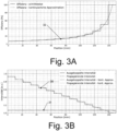
- FIGS Figures 3A and 3B An example of such a variable decoupling efficiency in the direction of arrow 24 is shown in FIGS Figures 3A and 3B shown.
- Figures 3A and 3B shows the x-axis a position along the decoupling hologram 22 in the direction of arrow 24 of FIG 2 .
- a decoupling hologram As an example of a decoupling hologram, a decoupling hologram with a length of 150 mm in the direction of arrow 24, a thickness of the waveguide substrate 20 of 2 mm and an angle of the coupled light 23 within the waveguide substrate 20 of 70° was used. These values are given as an example only and other configurations are also possible.
- curves 32 in Figure 3A show the decoupling efficiency in %, ie indicate what proportion of the light hitting the decoupling hologram is coupled out. The remaining portion is then passed on in the waveguide substrate in order to hit the decoupling hologram again.
- curves 30 in Figure 3B show the intensity of the wave propagating in the waveguide substrate 30.
- FIG. This intensity decreases continuously since a portion of the light is coupled out.
- Curves 31 show the decoupled intensity. Due to the increasing decoupling efficiency, the decoupled intensity is approximately constant, since an increasingly larger proportion of the decreasing intensity according to curves 30 is decoupled due to the increasing efficiency according to curves 32 .
- the curves 30-32 each have a first curve that indicates a step-by-step configuration that can be easily implemented technically, i.e. the properties of the decoupling hologram 22 are changed step-by-step and then remain the same for a specific area.
- a second curve shows a continuous approximation of this step-by-step behavior.
- Uniform illumination of the primary hologram over a large area can be realized by using such a varying decoupling efficiency.
- the outcoupling efficiency therefore increases with increasing distance from the incoupling hologram.
- the Figure 4A shows the already with reference to the 2 briefly discussed configuration.
- the coupling hologram 21 is arranged on an opposite side of the waveguide substrate 20 to the side on which the light beams 13 impinge.
- the coupling-in hologram 21 works here as a reflection grating, ie the light 13 is diffracted at the desired angle in reflection by the coupling-in hologram 21 in order to form the coupled-in light 23 .
- the coupling hologram 21 is arranged on the same side of the waveguide substrate 20 on which the light 13 falls on the waveguide substrate 20 .
- the coupling-in hologram 21 also works here as a reflection grating and reflects the incident light at a desired angle to a side of the coupling-in hologram 21 that faces away from the waveguide substrate 20 .
- the light diffracted in this way is totally reflected at the interface between the coupling-in hologram 21 and the environment and thus reaches the waveguide substrate 20 as coupled-in light 23.
- the coupling hologram is arranged on a side of the waveguide substrate 20 which is opposite to the side on which the light 13 impinges.
- the coupling hologram 21 works here as a transmission grating, i.e. the incident light 13 is diffracted at an angle in the direction of a side of the coupling hologram 21 facing away from the waveguide substrate 20 and is totally reflected at the interface between the coupling hologram 21 and the environment in order to enter the waveguide substrate as coupled light 23 20 to get to.
- the in-coupling hologram 21 is arranged on that side of the waveguide substrate 20 on which the light 13 falls on the waveguide substrate 20 and is designed as a transmission grating. The light 13 is thus diffracted by the in-coupling hologram 21 and directed into the waveguide substrate as in-coupled light 23 .
- the Figure 5A shows a configuration as already referred to in FIG 2 shown.
- the decoupling hologram 22 is arranged on a side of the waveguide substrate 20 which is opposite the side on which the illumination light 14 is decoupled.
- the decoupling hologram 22 works here as a reflection grating and uses Bragg planes 50 of the decoupling hologram 22 to bend the coupled-in light 23 in a direction that enables decoupling from the waveguide substrate 20, in particular essentially perpendicular to a surface of the waveguide substrate 20.
- the decoupling hologram 22 is arranged on the same side of the waveguide substrate on which the illumination light 14 is coupled out, and also works as a reflection grating.
- the coupled-in light 23 first goes without diffraction through the coupling-out hologram 22 to a side of the coupling-out hologram 22 facing away from the waveguide substrate 20, is reflected there and then diffracted by the coupling-out hologram 22 for coupling out as illumination light 14.
- the decoupling hologram is arranged on the same side of the waveguide substrate 20 on which the illumination light 14 is decoupled.
- the coupling-out hologram 22 works here as a transmission grating and bends the coupled-in light 23 in a direction that enables coupling out as illumination light 14, for example in a direction essentially perpendicular to the interface between the coupling-out hologram 22 and the environment.
- the decoupling hologram 22 is arranged on a side of the waveguide substrate 20 which is opposite the side on which the illumination light 14 is coupled out, and works as a transmission grating.
- the coupled-in light 23 first passes through the coupling-out hologram 22 , is reflected on a side of the coupling-out hologram 22 opposite the waveguide substrate 20 and then diffracted by Bragg planes 50 in order to be coupled out as illumination light 40 .
- the secondary hologram system 12 can be used in connection with various types of primary holograms, in particular transmission holograms, reflection holograms or also edge-illuminated holograms. This is now with reference to the Figures 6A to 6B explained.
- FIG 6A a configuration is shown in which as in 1 the primary hologram 11 operates as a transmission hologram.
- FIG 6B A configuration is shown in which the primary hologram 11 is configured as a reflection hologram.
- the illuminating light 14 falls on the same side of the primary hologram 11 from which the image light beams 15 emanate, in that the primary hologram 11 bends the illuminating light 14 in a corresponding light direction.
- FIGS Figures 6C and 6D finally show the possibility of edge-lit holograms, whereby I use both transmission holograms ( Figure 6C ) as well as reflection holograms ( Figure 6D ) can be used as the primary hologram 11.
- edge-lit means that the illumination light 14 is coupled into the primary hologram 11 via a side surface thereof, as is shown in FIGS Figures 6C and 6D is shown.
- the illumination light 14 is coupled in a direction into the primary hologram 11 towards the side from which the image light beams 15 emanate.
- the primary hologram 11 then works essentially as a transmission hologram.
- the illumination light 14 becomes as in Figure 6B coupled to the side of the primary hologram 11 opposite the side from which the image light rays 15 emanate.
- the primary hologram 11 works essentially as a reflection hologram. All of these configurations can be implemented in lighting devices according to the present invention and with the different variants for the secondary hologram system that are described with reference to FIG Figures 2-5 have been discussed can be combined.
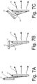
- the secondary hologram system 12 can be positioned at different angles in space to the primary hologram 11, whereby angles at which the illuminating light 14 emerges from the secondary hologram system can be adjusted accordingly. Examples of this are now with reference to the 7 explained.
- the arrangement of Figure 7A essentially corresponds to the arrangement of the 1 .
- a side of the secondary hologram system 12 from which the illumination light 14 is emitted is parallel to a side of the primary hologram where the illumination light 14 is received.
- these sides are perpendicular to each other.
- In the Figure 7C is an angle between the parallel arrangement of the Figure 7A and the vertical arrangement of the Figure 7B chosen. This can essentially be chosen arbitrarily if the direction in which the illumination light 14 is emitted from the secondary hologram system 12 is adjusted accordingly.
- the primary hologram 11 is a transmission hologram.
- reflection holograms as in Figure 6B shown or with edge-lit holograms as in FIGS Figures 6C and 6D shown possible.
- the secondary hologram system 12 generates collimated illumination light 14, ie the light beams of the illumination light 14 are essentially parallel to one another.
- other types of illumination light for example divergent or convergent illumination light, are also possible.
- the 8 shows a lighting device in which the illumination light 14, which emanates from the secondary hologram system 12, diverges. This leads to the arrangement of the 8 to the illumination light occurring at different points of the primary hologram 11 at different angles.
- the primary hologram 11 can be designed to produce the desired image at different locations in response to light incident at corresponding different angles. This can be done, for example, by a reference beam diverging in a corresponding manner when the primary hologram 11 is being created.
- the divergence can be in one direction, ie for example only in the cross-sectional view of FIG 8 direction shown, and collimated in a direction perpendicular thereto, ie substantially parallel, but it may also diverge in two directions. In many cases, however, a collimated illumination light 14 will be preferred.
- orientation of the primary hologram 11 itself to a direction in which the image is to be formed by the light rays 15 can be varied within the limits set by the technology of the hologram 11 (its extent and the desired image size).
- a secondary hologram system and a primary hologram 11 are provided in each case.
- multiple secondary hologram systems can also be used to illuminate a primary hologram with different wavelengths and/or at different angles, for example to selectively generate different images and thus implement different lighting functions.
- several images are recorded in the primary hologram 11, for example in the same layer of the primary hologram 11 or in layers lying one above the other. Since holograms are angle and wavelength selective, an appropriate image will only appear when illuminated at an appropriate angle (which in many cases corresponds to an angle of a reference beam when the image was captured) and at an appropriate wavelength (that of the wavelength of the rays used when the image was captured corresponds) reconstructed.
- An example of such a lighting device is in the Figures 9A and 9B shown.
- FIG. 12 is a plan view in a viewing direction indicated by an arrow 90 in FIG Figure 9A is indicated
- the side view of Figure 9A FIG. 14 is a side view in a viewing direction indicated by an arrow 91 in FIG Figure 9B is indicated.
- Figures 9A and 9B has a primary hologram 11 and four secondary hologram systems 12A, 12B, 12C and 12D.
- the primary hologram 11 is an edge-illuminated hologram, with illumination light 14A to 14D, which emanates from the respective secondary hologram systems 12A to 12D, being coupled into the primary hologram 11 via different edges and thus entering the primary hologram 11 at different angles.
- "Different angles" can mean different absolute angular amounts, but also different spatial directions with the same angular amount, or both.
- This can be used, for example, for various lighting functions such as brake lights or rear lights, or it can be used in some other way to convey information to drivers of other vehicles.
- the shape of a rear light function can change as a function of a distance from a Change the following vehicle to warn the driver of the following vehicle when it is tailgating.
Landscapes
- Physics & Mathematics (AREA)
- Optics & Photonics (AREA)
- General Physics & Mathematics (AREA)
- Engineering & Computer Science (AREA)
- General Engineering & Computer Science (AREA)
- Microelectronics & Electronic Packaging (AREA)
- Diffracting Gratings Or Hologram Optical Elements (AREA)
- Holo Graphy (AREA)
- Lighting Device Outwards From Vehicle And Optical Signal (AREA)
Claims (12)
- Dispositif d'éclairage (10) pour véhicules, présentant :un hologramme primaire (11) permettant de générer une fonction d'éclairage en réponse à un éclairage par une lumière d'éclairage (14), etun système d'hologramme secondaire (12), le système d'hologramme secondaire présentant :un substrat de guide d'ondes (20),un hologramme d'injection (21) pour injecter de la lumière (13) provenant d'une source de lumière (16) dans le substrat de guide d'ondes (20), etun hologramme d'extraction (22) pour extraire de la lumière du substrat de guide d'ondes (20) comme lumière d'éclairage (14).
- Dispositif d'éclairage (10) selon la revendication 1, dans lequel l'hologramme d'extraction présente un rendement d'extraction variable dans l'espace.
- Dispositif d'éclairage selon la revendication 2, dans lequel le rendement d'extraction augmente avec une distance croissante par rapport à l'hologramme d'injection (21).
- Dispositif d'éclairage (10) selon l'une quelconque des revendications 1 à 3, dans lequel l'hologramme d'injection (21) et/ou l'hologramme d'extraction (22) fournissent une fonction de filtre spectral.
- Dispositif d'éclairage (10) selon l'une quelconque des revendications 1 à 4, dans lequel l'hologramme d'injection (21) est agencé sous forme de réseau de transmission ou de réseau de réflexion.
- Dispositif d'éclairage (10) selon l'une quelconque des revendications 1 à 5, dans lequel l'hologramme d'extraction est agencé sous forme de réseau de transmission ou de réseau de réflexion.
- Dispositif d'éclairage (10) selon l'une quelconque des revendications 1 à 6, dans lequel l'hologramme d'extraction (22) est disposé sur un côté du substrat de guide d'ondes (20) tourné vers l'hologramme primaire (11) ou sur un côté du substrat de guide d'ondes (20) détourné de l'hologramme primaire (11).
- Dispositif d'éclairage (10) selon l'une quelconque des revendications 1 à 7, dans lequel l'hologramme primaire (11) est interchangeable.
- Dispositif d'éclairage (10) selon l'une quelconque des revendications 1 à 8, dans lequel l'hologramme primaire est un hologramme de transmission, un hologramme de réflexion, un hologramme de réflexion à éclairage par la tranche ou un hologramme de transmission à éclairage par la tranche.
- Dispositif d'éclairage (10) selon l'une quelconque des revendications 1 à 9, dans lequel le dispositif d'éclairage (10) présente une pluralité de systèmes d'hologramme secondaires, comprenant le système d'hologramme secondaire, dans lequel la pluralité de systèmes d'hologramme secondaires (12A à 12D) est agencée pour diriger la lumière d'éclairage (14A à 14B) respective sur l'hologramme primaire (11).
- Dispositif d'éclairage (10) selon la revendication 10, dans lequel l'hologramme primaire (11) met en œuvre une pluralité de fonctions d'éclairage, dans lequel une ou plusieurs fonctions d'éclairage de la pluralité de fonctions d'éclairage sont associées à la pluralité de systèmes d'hologramme secondaires (12A à 12D).
- Dispositif d'éclairage (10) selon l'une quelconque des revendications 1 à 11, présentant en outre la source de lumière (16), dans lequel l'hologramme d'injection est disposé sur un côté du substrat de guide d'ondes (20) tourné vers la source de lumière (16) ou sur un côté du substrat de guide d'ondes (20) détourné de la source de lumière (16).
Applications Claiming Priority (2)
| Application Number | Priority Date | Filing Date | Title |
|---|---|---|---|
| DE102018115574.3A DE102018115574A1 (de) | 2018-06-28 | 2018-06-28 | Leuchteneinrichtung für Fahrzeuge |
| PCT/EP2019/067122 WO2020002491A1 (fr) | 2018-06-28 | 2019-06-27 | Dispositif d'éclairage de véhicules |
Publications (2)
| Publication Number | Publication Date |
|---|---|
| EP3814816A1 EP3814816A1 (fr) | 2021-05-05 |
| EP3814816B1 true EP3814816B1 (fr) | 2023-03-08 |
Family
ID=67139719
Family Applications (1)
| Application Number | Title | Priority Date | Filing Date |
|---|---|---|---|
| EP19735265.1A Active EP3814816B1 (fr) | 2018-06-28 | 2019-06-27 | Dispositif d'éclairage de véhicules |
Country Status (6)
| Country | Link |
|---|---|
| US (1) | US11339943B2 (fr) |
| EP (1) | EP3814816B1 (fr) |
| CN (1) | CN112400126B (fr) |
| DE (1) | DE102018115574A1 (fr) |
| ES (1) | ES2943134T3 (fr) |
| WO (1) | WO2020002491A1 (fr) |
Cited By (1)
| Publication number | Priority date | Publication date | Assignee | Title |
|---|---|---|---|---|
| WO2025031998A1 (fr) * | 2023-08-09 | 2025-02-13 | Carl Zeiss Jena Gmbh | Dispositif d'éclairage et lampe de véhicule automobile |
Families Citing this family (6)
| Publication number | Priority date | Publication date | Assignee | Title |
|---|---|---|---|---|
| JP7259462B2 (ja) * | 2019-03-25 | 2023-04-18 | セイコーエプソン株式会社 | 表示装置 |
| GB2595452B (en) * | 2020-05-21 | 2022-10-26 | Jaguar Land Rover Ltd | Illumination device, method and system |
| WO2022238109A1 (fr) * | 2021-04-27 | 2022-11-17 | Carl Zeiss Jena Gmbh | Système optique pour hologramme flottant |
| CN113204185A (zh) * | 2021-05-10 | 2021-08-03 | 厦门大学 | 一种用于全息汽车尾灯的全息显示元件的制备方法 |
| DE102022104965A1 (de) | 2022-03-02 | 2023-09-07 | Carl Zeiss Jena Gmbh | Kompakte lichttechnische vorrichtung zur rekonstruktion eines hologramms |
| DE102023121274A1 (de) * | 2023-08-09 | 2025-02-13 | Carl Zeiss Jena Gmbh | Leuchtvorrichtung, kraftfahrzeugleuchte und verfahren zur herstellung einer leuchtvorrichtung |
Citations (1)
| Publication number | Priority date | Publication date | Assignee | Title |
|---|---|---|---|---|
| WO2019076985A1 (fr) * | 2017-10-18 | 2019-04-25 | Carl Zeiss Jena Gmbh | Dispositif d'éclairage pour véhicules |
Family Cites Families (50)
| Publication number | Priority date | Publication date | Assignee | Title |
|---|---|---|---|---|
| US4711512A (en) * | 1985-07-12 | 1987-12-08 | Environmental Research Institute Of Michigan | Compact head-up display |
| US4965152A (en) | 1988-01-15 | 1990-10-23 | E. I. Du Pont De Nemours And Company | Holographic notch filters |
| US5135751A (en) * | 1988-11-16 | 1992-08-04 | Mediventures Incorporated | Composition for reducing postsurgical adhesions |
| JP2817264B2 (ja) | 1989-10-04 | 1998-10-30 | 日産自動車株式会社 | 車両用表示器 |
| US5106174A (en) | 1990-04-16 | 1992-04-21 | Hughes Aircraft Company | Ideal distribution CHMSL hologram with double exposure technique |
| US5101193A (en) | 1990-04-16 | 1992-03-31 | Hughes Aircraft Company | Universal stand-alone holographic center high mounted stoplight |
| CA2039823C (fr) | 1990-04-16 | 1995-07-04 | Ronald T. Smith | Feu d'arret sureleve, a faisceau holographique, pour vehicule automobile |
| US5153751A (en) * | 1990-04-27 | 1992-10-06 | Central Glass Company, Limited | Holographic display element |
| JP3768542B2 (ja) | 1992-06-09 | 2006-04-19 | 株式会社デンソー | 表示装置 |
| US5341230A (en) | 1992-12-22 | 1994-08-23 | Hughes Aircraft Company | Waveguide holographic telltale display |
| US5347435A (en) | 1992-12-22 | 1994-09-13 | Hughes Aircraft Company | Linear lamp holographic trapped beam center high mounted stoplight |
| JPH06230225A (ja) | 1993-02-03 | 1994-08-19 | Nissan Motor Co Ltd | 表示装置 |
| JPH07192510A (ja) * | 1993-12-24 | 1995-07-28 | Nissan Motor Co Ltd | 車両用灯具 |
| JP3544010B2 (ja) | 1994-10-25 | 2004-07-21 | 本田技研工業株式会社 | 車両用灯火器 |
| US5745266A (en) | 1996-10-02 | 1998-04-28 | Raytheon Company | Quarter-wave film for brightness enhancement of holographic thin taillamp |
| AU5113898A (en) | 1996-12-02 | 1998-06-29 | Xiaoli Fu | Grating-in-etalon polarization insensitive wavelength division multiplexing devices |
| US6062710A (en) | 1998-06-04 | 2000-05-16 | Lighten Up Trading Company, Inc. | Light fixture with at least one lens or reflector as image magnifier and a diffuser for reducing glare |
| JP3254474B2 (ja) | 1999-09-03 | 2002-02-04 | 独立行政法人物質・材料研究機構 | 軟x線分光素子用材料 |
| JP2002277816A (ja) | 2001-03-21 | 2002-09-25 | Minolta Co Ltd | 映像表示装置 |
| KR100590535B1 (ko) | 2004-01-24 | 2006-06-15 | 삼성전자주식회사 | 백라이트 유니트 |
| US7255469B2 (en) | 2004-06-30 | 2007-08-14 | 3M Innovative Properties Company | Phosphor based illumination system having a light guide and an interference reflector |
| KR100619070B1 (ko) | 2005-03-08 | 2006-08-31 | 삼성전자주식회사 | 조명유닛 및 이를 채용한 화상투사장치 |
| US7986407B2 (en) | 2008-08-04 | 2011-07-26 | Ondax, Inc. | Method and apparatus using volume holographic wavelength blockers |
| JPWO2010061835A1 (ja) | 2008-11-26 | 2012-04-26 | コニカミノルタオプト株式会社 | 映像表示装置およびヘッドマウントディスプレイ |
| JP5804243B2 (ja) * | 2011-04-22 | 2015-11-04 | 大日本印刷株式会社 | 投射型映像表示装置 |
| DE102011079127A1 (de) | 2011-07-14 | 2013-01-17 | Seereal Technologies S.A. | Optische Vorrichtung für eine Beleuchtungsvorrichtung eines 3D-Displays |
| GB201115208D0 (en) * | 2011-09-02 | 2011-10-19 | Sec Dep For Business Innovation & Skills The | Hologram |
| US8915635B2 (en) | 2013-03-13 | 2014-12-23 | Hewlett-Packard Development Company, L.P. | Backlight having dual collimating reflectors |
| US10452025B2 (en) | 2013-11-04 | 2019-10-22 | Luminit Llc | Substrate-guided wave-based transparent holographic center high mounted stop light and method of fabrication thereof |
| KR102191963B1 (ko) | 2014-02-03 | 2020-12-17 | 삼성전자주식회사 | 홀로그램 디스플레이가 가능한 휴대용 기기 및 홀로그램 디스플레이 방법 |
| DE202014003241U1 (de) | 2014-04-15 | 2015-07-20 | GM Global Technology Operations LLC (n. d. Ges. d. Staates Delaware) | Holographische Anzeigevorrichtung, Fahrzeug mit holographischer Anzeigevorrichtung und Computerprogrammprodukt |
| US9557466B2 (en) | 2014-07-30 | 2017-01-31 | Leia, Inc | Multibeam diffraction grating-based color backlighting |
| DE102014223933A1 (de) * | 2014-11-25 | 2016-05-25 | Robert Bosch Gmbh | Scheinwerfermodul |
| DE102014117842A1 (de) | 2014-12-04 | 2016-06-09 | Hella Kgaa Hueck & Co. | Zusatzbremsleuchte für Fahrzeuge |
| CN104777535B (zh) | 2015-03-25 | 2017-05-24 | 东南大学 | 一种复用体全息光栅 |
| GB201510525D0 (en) | 2015-06-16 | 2015-07-29 | Jaguar Land Rover Ltd | Vehicular signalling system and method |
| EP3130950A1 (fr) | 2015-08-10 | 2017-02-15 | Multiphoton Optics Gmbh | Élement de deviation de rayonnement et element optique dote d'un element de deviation de rayonnement |
| US10180520B2 (en) | 2015-08-24 | 2019-01-15 | Akonia Holographics, Llc | Skew mirrors, methods of use, and methods of manufacture |
| DE102015115128B4 (de) * | 2015-09-09 | 2023-05-11 | HELLA GmbH & Co. KGaA | Beleuchtungsvorrichtung für Fahrzeuge |
| CN105652447B (zh) * | 2016-01-28 | 2018-04-03 | 上海理湃光晶技术有限公司 | 平面波导成像装置和方法 |
| CN105629474B (zh) * | 2016-03-07 | 2019-02-22 | 成都理想境界科技有限公司 | 一种近眼显示系统及头戴显示设备 |
| DE102016107307A1 (de) | 2016-04-20 | 2017-10-26 | Hella Kgaa Hueck & Co. | Beleuchtungsvorrichtung für Fahrzeuge |
| US20180074457A1 (en) | 2016-07-22 | 2018-03-15 | Massachusetts Institute Of Technology | Near-to-Eye and See-Through Holographic Displays |
| US10088118B2 (en) | 2016-08-30 | 2018-10-02 | HELLA GmbH & Co. KGaA | Light emitting area extender |
| DE102016117557A1 (de) * | 2016-09-19 | 2018-03-22 | HELLA GmbH & Co. KGaA | Beleuchtungsvorrichtung für Fahrzeuge |
| DE102016117969B4 (de) | 2016-09-23 | 2022-09-22 | Carl Zeiss Jena Gmbh | Leuchteinrichtung für Fahrzeuge |
| CN107167920B (zh) * | 2017-06-19 | 2020-06-30 | 东南大学 | 一种高亮度全息波导显示装置 |
| CN107966820B (zh) * | 2017-12-27 | 2021-03-02 | 北京灵犀微光科技有限公司 | 波导显示装置 |
| JP7081977B2 (ja) | 2018-05-17 | 2022-06-07 | スタンレー電気株式会社 | 車両用灯具 |
| DE102018116670A1 (de) | 2018-07-10 | 2020-01-16 | Carl Zeiss Jena Gmbh | Lichtquelle für holographiebasierte Leuchteneinrichtung |
-
2018
- 2018-06-28 DE DE102018115574.3A patent/DE102018115574A1/de active Pending
-
2019
- 2019-06-27 WO PCT/EP2019/067122 patent/WO2020002491A1/fr not_active Ceased
- 2019-06-27 EP EP19735265.1A patent/EP3814816B1/fr active Active
- 2019-06-27 ES ES19735265T patent/ES2943134T3/es active Active
- 2019-06-27 US US17/255,718 patent/US11339943B2/en active Active
- 2019-06-27 CN CN201980043461.8A patent/CN112400126B/zh active Active
Patent Citations (1)
| Publication number | Priority date | Publication date | Assignee | Title |
|---|---|---|---|---|
| WO2019076985A1 (fr) * | 2017-10-18 | 2019-04-25 | Carl Zeiss Jena Gmbh | Dispositif d'éclairage pour véhicules |
Cited By (1)
| Publication number | Priority date | Publication date | Assignee | Title |
|---|---|---|---|---|
| WO2025031998A1 (fr) * | 2023-08-09 | 2025-02-13 | Carl Zeiss Jena Gmbh | Dispositif d'éclairage et lampe de véhicule automobile |
Also Published As
| Publication number | Publication date |
|---|---|
| US11339943B2 (en) | 2022-05-24 |
| CN112400126A (zh) | 2021-02-23 |
| CN112400126B (zh) | 2023-06-30 |
| ES2943134T3 (es) | 2023-06-09 |
| WO2020002491A1 (fr) | 2020-01-02 |
| US20210270441A1 (en) | 2021-09-02 |
| DE102018115574A1 (de) | 2020-01-02 |
| EP3814816A1 (fr) | 2021-05-05 |
Similar Documents
| Publication | Publication Date | Title |
|---|---|---|
| EP3814816B1 (fr) | Dispositif d'éclairage de véhicules | |
| DE102015102243B4 (de) | Beleuchtungsvorrichtung für Fahrzeuge | |
| EP3237795B1 (fr) | Dispositif d'éclairage pour véhicules | |
| WO2017042345A1 (fr) | Dispositif d'éclairage pour véhicules | |
| WO2015173695A2 (fr) | Dispositif d'affichage, dispositif rétroviseur et véhicule automobile | |
| DE102012112075A1 (de) | Beleuchtungsvorrichtung für Fahrzeuge | |
| DE102012100205A1 (de) | Optische Anordnung | |
| DE102014117842A1 (de) | Zusatzbremsleuchte für Fahrzeuge | |
| EP2530503A1 (fr) | Dispositif d`éclairage | |
| EP2502784B1 (fr) | Lampe de véhicule, en particulier pour éclairer l'intérieur du véhicule | |
| WO2013104781A1 (fr) | Dispositif optique permettant d'éclairer une matrice de pixels et/ou un modulateur de lumière spatial commandable pour un affichage | |
| EP2607776A2 (fr) | Dispositif d'éclairage pour un véhicule automobile avec une structure de guide de lumière | |
| DE102008044357A1 (de) | Fahrzeugleuchte und Verfahren zum Herstellen eines transparenten Elementes für eine Fahrzeugleuchte | |
| EP3899358B1 (fr) | Dispositif d'éclairage pour un phare de véhicule automobile ainsi que phare de véhicule automobile | |
| DE102013008075A1 (de) | Leuchtvorrichtung mit nichtlinearem Lichtleiter für ein Kraftfahrzeug | |
| EP2618045A1 (fr) | Dispositif dýéclairage pour un véhicule automobile | |
| DE102011051045A1 (de) | Lichtleitmodul und Leuchte für Fahrzeuge | |
| DE102008015131B4 (de) | Kraftfahrzeugbeleuchtungseinrichtung und Lichtleiterstruktur für eine Kraftfahrzeugbeleuchtungseinrichtung | |
| EP2927572A1 (fr) | Lampe de véhicule automobile avec effet d'essuyage | |
| EP3158260B1 (fr) | Dispositif d'éclairage de véhicule automobile | |
| DE102013007856A1 (de) | Lichtleitkörper und Leuchtvorrichtung mit dem Lichtleitkörper | |
| DE102021210915A1 (de) | Holographisches bedienelement | |
| DE102013103410A1 (de) | Beleuchtungsvorrichtung für Fahrzeuge | |
| EP2500754A1 (fr) | Dispositif d'éclairage pour véhicule automobile | |
| EP3812653B1 (fr) | Feu de signalisation pourvu de guide de lumière |
Legal Events
| Date | Code | Title | Description |
|---|---|---|---|
| STAA | Information on the status of an ep patent application or granted ep patent |
Free format text: STATUS: UNKNOWN |
|
| STAA | Information on the status of an ep patent application or granted ep patent |
Free format text: STATUS: THE INTERNATIONAL PUBLICATION HAS BEEN MADE |
|
| PUAI | Public reference made under article 153(3) epc to a published international application that has entered the european phase |
Free format text: ORIGINAL CODE: 0009012 |
|
| STAA | Information on the status of an ep patent application or granted ep patent |
Free format text: STATUS: REQUEST FOR EXAMINATION WAS MADE |
|
| 17P | Request for examination filed |
Effective date: 20210112 |
|
| AK | Designated contracting states |
Kind code of ref document: A1 Designated state(s): AL AT BE BG CH CY CZ DE DK EE ES FI FR GB GR HR HU IE IS IT LI LT LU LV MC MK MT NL NO PL PT RO RS SE SI SK SM TR |
|
| DAV | Request for validation of the european patent (deleted) | ||
| DAX | Request for extension of the european patent (deleted) | ||
| GRAP | Despatch of communication of intention to grant a patent |
Free format text: ORIGINAL CODE: EPIDOSNIGR1 |
|
| STAA | Information on the status of an ep patent application or granted ep patent |
Free format text: STATUS: GRANT OF PATENT IS INTENDED |
|
| INTG | Intention to grant announced |
Effective date: 20220928 |
|
| GRAS | Grant fee paid |
Free format text: ORIGINAL CODE: EPIDOSNIGR3 |
|
| GRAA | (expected) grant |
Free format text: ORIGINAL CODE: 0009210 |
|
| STAA | Information on the status of an ep patent application or granted ep patent |
Free format text: STATUS: THE PATENT HAS BEEN GRANTED |
|
| AK | Designated contracting states |
Kind code of ref document: B1 Designated state(s): AL AT BE BG CH CY CZ DE DK EE ES FI FR GB GR HR HU IE IS IT LI LT LU LV MC MK MT NL NO PL PT RO RS SE SI SK SM TR |
|
| REG | Reference to a national code |
Ref country code: CH Ref legal event code: EP Ref country code: AT Ref legal event code: REF Ref document number: 1552970 Country of ref document: AT Kind code of ref document: T Effective date: 20230315 |
|
| REG | Reference to a national code |
Ref country code: DE Ref legal event code: R096 Ref document number: 502019007168 Country of ref document: DE |
|
| REG | Reference to a national code |
Ref country code: IE Ref legal event code: FG4D Free format text: LANGUAGE OF EP DOCUMENT: GERMAN |
|
| REG | Reference to a national code |
Ref country code: CH Ref legal event code: PK Free format text: BERICHTIGUNGEN |
|
| REG | Reference to a national code |
Ref country code: DE Ref legal event code: R083 Ref document number: 502019007168 Country of ref document: DE |
|
| RIN2 | Information on inventor provided after grant (corrected) |
Inventor name: VOJTISEK, PETR |
|
| REG | Reference to a national code |
Ref country code: ES Ref legal event code: FG2A Ref document number: 2943134 Country of ref document: ES Kind code of ref document: T3 Effective date: 20230609 |
|
| REG | Reference to a national code |
Ref country code: LT Ref legal event code: MG9D |
|
| REG | Reference to a national code |
Ref country code: NL Ref legal event code: MP Effective date: 20230308 |
|
| PG25 | Lapsed in a contracting state [announced via postgrant information from national office to epo] |
Ref country code: RS Free format text: LAPSE BECAUSE OF FAILURE TO SUBMIT A TRANSLATION OF THE DESCRIPTION OR TO PAY THE FEE WITHIN THE PRESCRIBED TIME-LIMIT Effective date: 20230308 Ref country code: NO Free format text: LAPSE BECAUSE OF FAILURE TO SUBMIT A TRANSLATION OF THE DESCRIPTION OR TO PAY THE FEE WITHIN THE PRESCRIBED TIME-LIMIT Effective date: 20230608 Ref country code: LV Free format text: LAPSE BECAUSE OF FAILURE TO SUBMIT A TRANSLATION OF THE DESCRIPTION OR TO PAY THE FEE WITHIN THE PRESCRIBED TIME-LIMIT Effective date: 20230308 Ref country code: LT Free format text: LAPSE BECAUSE OF FAILURE TO SUBMIT A TRANSLATION OF THE DESCRIPTION OR TO PAY THE FEE WITHIN THE PRESCRIBED TIME-LIMIT Effective date: 20230308 Ref country code: HR Free format text: LAPSE BECAUSE OF FAILURE TO SUBMIT A TRANSLATION OF THE DESCRIPTION OR TO PAY THE FEE WITHIN THE PRESCRIBED TIME-LIMIT Effective date: 20230308 |
|
| PG25 | Lapsed in a contracting state [announced via postgrant information from national office to epo] |
Ref country code: SE Free format text: LAPSE BECAUSE OF FAILURE TO SUBMIT A TRANSLATION OF THE DESCRIPTION OR TO PAY THE FEE WITHIN THE PRESCRIBED TIME-LIMIT Effective date: 20230308 Ref country code: NL Free format text: LAPSE BECAUSE OF FAILURE TO SUBMIT A TRANSLATION OF THE DESCRIPTION OR TO PAY THE FEE WITHIN THE PRESCRIBED TIME-LIMIT Effective date: 20230308 Ref country code: GR Free format text: LAPSE BECAUSE OF FAILURE TO SUBMIT A TRANSLATION OF THE DESCRIPTION OR TO PAY THE FEE WITHIN THE PRESCRIBED TIME-LIMIT Effective date: 20230609 Ref country code: FI Free format text: LAPSE BECAUSE OF FAILURE TO SUBMIT A TRANSLATION OF THE DESCRIPTION OR TO PAY THE FEE WITHIN THE PRESCRIBED TIME-LIMIT Effective date: 20230308 |
|
| PG25 | Lapsed in a contracting state [announced via postgrant information from national office to epo] |
Ref country code: SM Free format text: LAPSE BECAUSE OF FAILURE TO SUBMIT A TRANSLATION OF THE DESCRIPTION OR TO PAY THE FEE WITHIN THE PRESCRIBED TIME-LIMIT Effective date: 20230308 Ref country code: RO Free format text: LAPSE BECAUSE OF FAILURE TO SUBMIT A TRANSLATION OF THE DESCRIPTION OR TO PAY THE FEE WITHIN THE PRESCRIBED TIME-LIMIT Effective date: 20230308 Ref country code: PT Free format text: LAPSE BECAUSE OF FAILURE TO SUBMIT A TRANSLATION OF THE DESCRIPTION OR TO PAY THE FEE WITHIN THE PRESCRIBED TIME-LIMIT Effective date: 20230710 Ref country code: EE Free format text: LAPSE BECAUSE OF FAILURE TO SUBMIT A TRANSLATION OF THE DESCRIPTION OR TO PAY THE FEE WITHIN THE PRESCRIBED TIME-LIMIT Effective date: 20230308 Ref country code: CZ Free format text: LAPSE BECAUSE OF FAILURE TO SUBMIT A TRANSLATION OF THE DESCRIPTION OR TO PAY THE FEE WITHIN THE PRESCRIBED TIME-LIMIT Effective date: 20230308 |
|
| PG25 | Lapsed in a contracting state [announced via postgrant information from national office to epo] |
Ref country code: SK Free format text: LAPSE BECAUSE OF FAILURE TO SUBMIT A TRANSLATION OF THE DESCRIPTION OR TO PAY THE FEE WITHIN THE PRESCRIBED TIME-LIMIT Effective date: 20230308 Ref country code: PL Free format text: LAPSE BECAUSE OF FAILURE TO SUBMIT A TRANSLATION OF THE DESCRIPTION OR TO PAY THE FEE WITHIN THE PRESCRIBED TIME-LIMIT Effective date: 20230308 Ref country code: IS Free format text: LAPSE BECAUSE OF FAILURE TO SUBMIT A TRANSLATION OF THE DESCRIPTION OR TO PAY THE FEE WITHIN THE PRESCRIBED TIME-LIMIT Effective date: 20230708 |
|
| REG | Reference to a national code |
Ref country code: DE Ref legal event code: R097 Ref document number: 502019007168 Country of ref document: DE |
|
| PLBE | No opposition filed within time limit |
Free format text: ORIGINAL CODE: 0009261 |
|
| STAA | Information on the status of an ep patent application or granted ep patent |
Free format text: STATUS: NO OPPOSITION FILED WITHIN TIME LIMIT |
|
| PG25 | Lapsed in a contracting state [announced via postgrant information from national office to epo] |
Ref country code: MC Free format text: LAPSE BECAUSE OF FAILURE TO SUBMIT A TRANSLATION OF THE DESCRIPTION OR TO PAY THE FEE WITHIN THE PRESCRIBED TIME-LIMIT Effective date: 20230308 |
|
| PG25 | Lapsed in a contracting state [announced via postgrant information from national office to epo] |
Ref country code: SI Free format text: LAPSE BECAUSE OF FAILURE TO SUBMIT A TRANSLATION OF THE DESCRIPTION OR TO PAY THE FEE WITHIN THE PRESCRIBED TIME-LIMIT Effective date: 20230308 Ref country code: MC Free format text: LAPSE BECAUSE OF FAILURE TO SUBMIT A TRANSLATION OF THE DESCRIPTION OR TO PAY THE FEE WITHIN THE PRESCRIBED TIME-LIMIT Effective date: 20230308 Ref country code: DK Free format text: LAPSE BECAUSE OF FAILURE TO SUBMIT A TRANSLATION OF THE DESCRIPTION OR TO PAY THE FEE WITHIN THE PRESCRIBED TIME-LIMIT Effective date: 20230308 |
|
| REG | Reference to a national code |
Ref country code: CH Ref legal event code: PL |
|
| 26N | No opposition filed |
Effective date: 20231211 |
|
| REG | Reference to a national code |
Ref country code: BE Ref legal event code: MM Effective date: 20230630 |
|
| PG25 | Lapsed in a contracting state [announced via postgrant information from national office to epo] |
Ref country code: LU Free format text: LAPSE BECAUSE OF NON-PAYMENT OF DUE FEES Effective date: 20230627 |
|
| REG | Reference to a national code |
Ref country code: IE Ref legal event code: MM4A |
|
| PG25 | Lapsed in a contracting state [announced via postgrant information from national office to epo] |
Ref country code: LU Free format text: LAPSE BECAUSE OF NON-PAYMENT OF DUE FEES Effective date: 20230627 |
|
| PG25 | Lapsed in a contracting state [announced via postgrant information from national office to epo] |
Ref country code: IE Free format text: LAPSE BECAUSE OF NON-PAYMENT OF DUE FEES Effective date: 20230627 |
|
| PG25 | Lapsed in a contracting state [announced via postgrant information from national office to epo] |
Ref country code: IE Free format text: LAPSE BECAUSE OF NON-PAYMENT OF DUE FEES Effective date: 20230627 Ref country code: CH Free format text: LAPSE BECAUSE OF NON-PAYMENT OF DUE FEES Effective date: 20230630 |
|
| PG25 | Lapsed in a contracting state [announced via postgrant information from national office to epo] |
Ref country code: IT Free format text: LAPSE BECAUSE OF FAILURE TO SUBMIT A TRANSLATION OF THE DESCRIPTION OR TO PAY THE FEE WITHIN THE PRESCRIBED TIME-LIMIT Effective date: 20230308 Ref country code: BE Free format text: LAPSE BECAUSE OF NON-PAYMENT OF DUE FEES Effective date: 20230630 |
|
| PG25 | Lapsed in a contracting state [announced via postgrant information from national office to epo] |
Ref country code: BG Free format text: LAPSE BECAUSE OF FAILURE TO SUBMIT A TRANSLATION OF THE DESCRIPTION OR TO PAY THE FEE WITHIN THE PRESCRIBED TIME-LIMIT Effective date: 20230308 |
|
| PG25 | Lapsed in a contracting state [announced via postgrant information from national office to epo] |
Ref country code: BG Free format text: LAPSE BECAUSE OF FAILURE TO SUBMIT A TRANSLATION OF THE DESCRIPTION OR TO PAY THE FEE WITHIN THE PRESCRIBED TIME-LIMIT Effective date: 20230308 |
|
| PGFP | Annual fee paid to national office [announced via postgrant information from national office to epo] |
Ref country code: DE Payment date: 20250618 Year of fee payment: 7 |
|
| PGFP | Annual fee paid to national office [announced via postgrant information from national office to epo] |
Ref country code: GB Payment date: 20250618 Year of fee payment: 7 |
|
| PGFP | Annual fee paid to national office [announced via postgrant information from national office to epo] |
Ref country code: FR Payment date: 20250627 Year of fee payment: 7 |
|
| PG25 | Lapsed in a contracting state [announced via postgrant information from national office to epo] |
Ref country code: CY Free format text: LAPSE BECAUSE OF FAILURE TO SUBMIT A TRANSLATION OF THE DESCRIPTION OR TO PAY THE FEE WITHIN THE PRESCRIBED TIME-LIMIT; INVALID AB INITIO Effective date: 20190627 |
|
| REG | Reference to a national code |
Ref country code: AT Ref legal event code: MM01 Ref document number: 1552970 Country of ref document: AT Kind code of ref document: T Effective date: 20240627 |
|
| PG25 | Lapsed in a contracting state [announced via postgrant information from national office to epo] |
Ref country code: HU Free format text: LAPSE BECAUSE OF FAILURE TO SUBMIT A TRANSLATION OF THE DESCRIPTION OR TO PAY THE FEE WITHIN THE PRESCRIBED TIME-LIMIT; INVALID AB INITIO Effective date: 20190627 |
|
| PGFP | Annual fee paid to national office [announced via postgrant information from national office to epo] |
Ref country code: ES Payment date: 20250731 Year of fee payment: 7 |
|
| PG25 | Lapsed in a contracting state [announced via postgrant information from national office to epo] |
Ref country code: AT Free format text: LAPSE BECAUSE OF NON-PAYMENT OF DUE FEES Effective date: 20240627 |
|
| PG25 | Lapsed in a contracting state [announced via postgrant information from national office to epo] |
Ref country code: TR Free format text: LAPSE BECAUSE OF FAILURE TO SUBMIT A TRANSLATION OF THE DESCRIPTION OR TO PAY THE FEE WITHIN THE PRESCRIBED TIME-LIMIT Effective date: 20230308 |
|
| PGFP | Annual fee paid to national office [announced via postgrant information from national office to epo] |
Ref country code: AT Payment date: 20260410 Year of fee payment: 5 |