EP3513256B1 - Dispositif de régulation et procédé - Google Patents
Dispositif de régulation et procédé Download PDFInfo
- Publication number
- EP3513256B1 EP3513256B1 EP17777500.4A EP17777500A EP3513256B1 EP 3513256 B1 EP3513256 B1 EP 3513256B1 EP 17777500 A EP17777500 A EP 17777500A EP 3513256 B1 EP3513256 B1 EP 3513256B1
- Authority
- EP
- European Patent Office
- Prior art keywords
- dead zone
- variable
- controller
- disturbance variable
- disturbance
- Prior art date
- Legal status (The legal status is an assumption and is not a legal conclusion. Google has not performed a legal analysis and makes no representation as to the accuracy of the status listed.)
- Active
Links
- 238000000034 method Methods 0.000 title claims description 35
- 230000008569 process Effects 0.000 claims description 20
- 238000004590 computer program Methods 0.000 claims description 8
- 230000006870 function Effects 0.000 claims description 7
- 238000010438 heat treatment Methods 0.000 claims description 7
- 239000000126 substance Substances 0.000 claims 6
- 230000001105 regulatory effect Effects 0.000 claims 3
- 239000000654 additive Substances 0.000 claims 2
- 230000000996 additive effect Effects 0.000 claims 2
- 239000002826 coolant Substances 0.000 claims 2
- 230000001276 controlling effect Effects 0.000 claims 1
- 238000013500 data storage Methods 0.000 claims 1
- 230000000694 effects Effects 0.000 description 10
- 230000008859 change Effects 0.000 description 5
- 239000003795 chemical substances by application Substances 0.000 description 4
- 238000001816 cooling Methods 0.000 description 4
- 230000008878 coupling Effects 0.000 description 4
- 238000010168 coupling process Methods 0.000 description 4
- 238000005859 coupling reaction Methods 0.000 description 4
- 238000010586 diagram Methods 0.000 description 4
- 230000003472 neutralizing effect Effects 0.000 description 4
- 238000011144 upstream manufacturing Methods 0.000 description 4
- 230000004913 activation Effects 0.000 description 3
- 238000001914 filtration Methods 0.000 description 3
- 230000008901 benefit Effects 0.000 description 2
- 238000006243 chemical reaction Methods 0.000 description 2
- 239000000498 cooling water Substances 0.000 description 2
- 239000002994 raw material Substances 0.000 description 2
- 239000000523 sample Substances 0.000 description 2
- 206010006784 Burning sensation Diseases 0.000 description 1
- LFQSCWFLJHTTHZ-UHFFFAOYSA-N Ethanol Chemical compound CCO LFQSCWFLJHTTHZ-UHFFFAOYSA-N 0.000 description 1
- 230000006399 behavior Effects 0.000 description 1
- 230000009849 deactivation Effects 0.000 description 1
- 230000000368 destabilizing effect Effects 0.000 description 1
- 230000006866 deterioration Effects 0.000 description 1
- 238000011161 development Methods 0.000 description 1
- 230000018109 developmental process Effects 0.000 description 1
- 238000004821 distillation Methods 0.000 description 1
- 238000005265 energy consumption Methods 0.000 description 1
- 230000002349 favourable effect Effects 0.000 description 1
- 238000009499 grossing Methods 0.000 description 1
- 230000006872 improvement Effects 0.000 description 1
- 230000002045 lasting effect Effects 0.000 description 1
- 230000009467 reduction Effects 0.000 description 1
- 238000005070 sampling Methods 0.000 description 1
- 239000007858 starting material Substances 0.000 description 1
Images

Classifications
-
- G—PHYSICS
- G05—CONTROLLING; REGULATING
- G05B—CONTROL OR REGULATING SYSTEMS IN GENERAL; FUNCTIONAL ELEMENTS OF SUCH SYSTEMS; MONITORING OR TESTING ARRANGEMENTS FOR SUCH SYSTEMS OR ELEMENTS
- G05B5/00—Anti-hunting arrangements
- G05B5/01—Anti-hunting arrangements electric
-
- G—PHYSICS
- G05—CONTROLLING; REGULATING
- G05B—CONTROL OR REGULATING SYSTEMS IN GENERAL; FUNCTIONAL ELEMENTS OF SUCH SYSTEMS; MONITORING OR TESTING ARRANGEMENTS FOR SUCH SYSTEMS OR ELEMENTS
- G05B13/00—Adaptive control systems, i.e. systems automatically adjusting themselves to have a performance which is optimum according to some preassigned criterion
- G05B13/02—Adaptive control systems, i.e. systems automatically adjusting themselves to have a performance which is optimum according to some preassigned criterion electric
- G05B13/0205—Adaptive control systems, i.e. systems automatically adjusting themselves to have a performance which is optimum according to some preassigned criterion electric not using a model or a simulator of the controlled system
Definitions
- the invention relates to a control device and a control method.
- the manipulated variable is generated by a controller from the control deviation supplied to it, the controller controlling the process via an actuator.
- the controlled variable can be influenced by disturbance variables.
- H The control variable and manipulated variable are simply equated.
- the buffer level control which is a level control for a buffer tank in which the level is not to be kept exactly but within defined limits.
- the level is controlled by a valve as an actuator in the process.
- the inflow represents a disturbance variable.
- the EP 2 579 112 B1 proposed a control device in which the regulator dead zone element connected upstream of the regulator can be deactivated and reactivated, the control deviation supplied to the regulator being influenced by the regulator dead zone in the active state of the regulator dead zone and uninfluenced in the inactive state. If the control deviation exceeds a first threshold value (which can be equal to the dead zone limit), the dead zone element is deactivated and is only activated again when the control deviation falls below a second threshold value which is smaller than the first threshold value.
- a first threshold value which can be equal to the dead zone limit
- a disadvantage of the dead zone control is that disturbance variables are compensated for more poorly because the controlled variable must first leave the dead zone in order to activate the regulation and counteract the disturbance variable.
- a dead-beat controller for electric drives.
- a dead-beat controller is a discrete-time controller that converts the controlled system into a new setpoint in as few sampling steps as possible. Since the dead-beat controller, unlike a PI controller, has no integrating component, an estimated disturbance variable is applied to compensate for stationary offsets of the manipulated variable generated by the controller.
- a large smoothing factor also entails a large delay, which in turn can lead to the intended effect of the feedforward control, namely a quick reaction to disturbances, being weakened.
- a single change in a fault can lead to a slow but longer lasting change in the low-pass filtered interference signal, so that this can result in continuous actuator activity.
- the disturbance deadband element arranged downstream of the low-pass filter.
- the time constant of the low-pass filter can be selected to be significantly smaller. By the smaller time constant reduces both the filter effect and the time delay.
- the disturbance variable continues to fluctuate after low-pass filtering, but less so than originally.
- the disturbance variable dead zone now keeps the value of the disturbance variable feed-in constant as long as the fluctuation of the filtered disturbance variable takes place within the defined limits of the dead zone.
- This applies to the noise and small fluctuations in the disturbance variable in normal operation, so that an average constant disturbance variable does not cause actuator activity.
- the time constant of the low-pass filter should be chosen so small that a significant change in the disturbance variable exceeds the dead band comparatively quickly and thus has an effect in the disturbance variable feedforward.
- the position of the disturbance variable dead zone must be adjusted accordingly.
- a control device for controlling the disturbance variable dead zone element which compares the current position of the disturbance variable dead zone with the low-pass filtered disturbance variable and changes it to the current value of the low-pass filtered disturbance variable if the deviation exceeds a predetermined value.
- this is done e.g. B. by changing the position of the disturbance variable dead zone by the amount of half the dead zone width when the low-pass filtered disturbance variable leaves the dead zone, so that the current value of the disturbance variable at this time lies in the middle of the changed dead zone.
- the control devices of the two dead zone elements are coupled to one another, wherein the disturbance variable dead zone element can also be activated and deactivated by its control device and is temporarily deactivated when the control deviation leaves the controller dead zone. If the controlled variable leaves the controller dead zone, the control becomes active. Because at this point in time increased actuator activity is unavoidable, the dead zone of the disturbance variable can be temporarily deactivated. In an advantageous manner, both dead zones can be temporarily deactivated until the control deviation is very small. By coupling the disturbance variable dead zone to the controller dead zone, the controlled variable can be returned to the setpoint more quickly and the manipulated variable can be brought back to constant operation more quickly.
- the controller dead zone can also be temporarily deactivated. On the one hand, it can be prevented from leaving the controller dead zone by preventively returning the controlled variable to the vicinity of the setpoint. In general, however, this also results in frequent changes in the manipulated variable. Coupling the controller dead zone to the disturbance dead zone can make sense in certain cases, but generally leads to more actuator activity.
- the control device can advantageously be part of a buffer level control in which the fill level measured in a buffer store is used as the controlled variable, the measured inflow into the buffer store as the disturbance variable and the flow from the buffer store as the variable to be set.
- Another advantageous application is e.g. B. the pH value control of a medium in a container by metered supply of a neutralizing agent, the pH measured in the outlet of the container as the control variable y, the pH measured in the feed as the disturbance variable and the dosage of the supplied neutralizing agent as the size to be set is used.
- control method that can be carried out with the control device is preferably implemented in software or a combination of software / hardware, so that the invention also relates to a computer program with program code instructions that can be executed by a computer for implementing the method.
- the invention also relates to a computer program product, in particular a data carrier or a storage medium, with such a computer program that can be executed by a computer.
- Such a computer program is preferably part of an automation device by means of which the control device is implemented, or is held in a memory of the automation device or can be loaded into this memory, so that when the automation device is in operation, the method to control the fill level in a buffer memory.
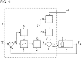
- Figure 1 shows the block diagram of a control device 1 for controlling a controlled variable y in a process 2.
- the current value (actual value) of the controlled variable y is compared with a reference variable (setpoint) w.
- a control deviation e calculated as the difference between the reference variable w and the actual values of the control variable y is fed via a controller dead zone element 3 to a controller 4, which generates a manipulated variable u from the control deviation e and with it via an actuator 5 controls process 2.
- the controlled variable y is influenced by a disturbance variable d which can be measured here and which affects the process.
- the controller dead zone element 3 is corresponding to that from the above EP 2 579 112 B1 known dead zone element formed and set by parameterization to a permissible fluctuation range of the controlled variable y. This means that the controlled variable y should not be controlled exactly to the setpoint w, but should only be kept within defined limits.
- the regulator dead zone element 3 is as in FIG EP 2 579 112 B1 described, provided with a control device 6 for its automatic activation and deactivation, the control deviation e supplied to the controller 4 being influenced by the controller dead zone element 3 in the active state of the controller dead zone and being uninfluenced in the inactive state.
- the controller dead zone element 3 is automatically deactivated by the control device 6 when the control deviation e exceeds a first threshold value and is reactivated when the control deviation e falls below a second threshold value that is smaller than the first threshold value.
- a controller includes all functions that help to generate the manipulated variable u from the control deviation e. B.
- the activation element 7 contains a correction element 9 and a low-pass filter 10.
- the correction element 9 serves to take into account a possible non-linearity of the influence of the disturbance variable d on the controlled variable y.
- the correction can be made using an empirically predetermined characteristic curve. For example, different disturbance variable values are set and for this purpose the respective manipulated variable values (including the connected auxiliary manipulated variable) are determined, which are necessary in order to keep the controlled variable reasonably constant with the respectively set disturbance variable values.
- the low-pass filter 10 serves to smooth the possibly corrected disturbance variable d, so that noise and small fluctuations in the filtered disturbance variable or the auxiliary manipulated variable u * are no longer noticeable.
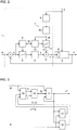
- FIG. 2 shows a further embodiment of the control device 1, which is different from the example Figure 1 differs in that the low-pass filter 10 is followed by a disturbance variable dead zone element 11.
- the disturbance variable dead zone element 11 serves to keep the value of the disturbance variable feed-in constant as long as the noise and the fluctuations of the filtered disturbance variable d * take place within the limits of the disturbance variable dead zone.
- the time constant of the low-pass filter 10 can therefore be selected to be comparatively small in order to reduce the time delay associated with the low-pass filtering and the consequent slowing down of the reaction of the disturbance variable application to disturbances.
- the position of the disturbance variable dead zone is tracked accordingly so that the disturbance variable d lies on average within the disturbance variable dead zone.
- the disturbance variable dead zone element 11 is controlled by a further control device 12, which controls the current position, e.g. B. the middle, the disturbance variable dead zone with the low-pass filtered disturbance variable d * and changes to their current value if the deviation exceeds a predetermined amount.
- Figure 3 shows an example of the position adjustment of the disturbance variable dead zone to the disturbance variable in a simplified form of a signal flow diagram in the graphic programming language CFC (Continuous Function Chart).
- a value ⁇ corresponding to half the width of the disturbance variable dead zone is added to a value of the low-pass filtered disturbance variable d * that is stored and is currently output as the auxiliary manipulated variable u * and subtracted from the auxiliary manipulated variable u * in a subtractor 14.
- the low-pass filtered disturbance variable d * is compared in a comparator 15 with each of the two dead zone limits u * + ⁇ and u * - ⁇ . For the two comparisons, the comparator 15 generates two output signals H and L, both of which have the logical value "0" if the low-pass filtered disturbance variable d * is within the current disturbance variable dead zone, and each assume the logical value "1" if the low-pass filtered disturbance variable d * exceeds the relevant limit (e.g. the lower limit is exceeded).
- An OR gate 16 generates a control signal St with the value "1" as soon as one of the two dead zone limits is exceeded, and thus controls a selection element 17 which, in the event of a limit violation, outputs the value of the auxiliary manipulated variable u * previously output by the current value of low-pass filtered disturbance variable d * replaced.
- control devices 6, 12 of the two dead zone elements 3, 11 are coupled to one another (coupling 18) so that they can control one another. If the Control variable e leaves the controller dead zone, the control becomes active so that there is increased actuator activity. is. Therefore, the further control unit 11 temporarily deactivates the disturbance variable dead zone in this case. Furthermore, both dead zones can be temporarily deactivated until the control deviation e is very small.
- the controlled variable y can be returned to the setpoint w faster and the value of the manipulated variable u - u * can be brought back to constant operation faster.
- the controller dead zone can also be temporarily deactivated when the disturbance variable d * exceeds its dead zone, in order to prevent the control variable y from returning close to the setpoint w and to prevent the control deviation e from leaving the controller dead zone.
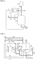
- FIG. 4 shows the control device 1 as a component of a buffer level control, in which a container (e.g. tank) serves as a buffer container 19 in a system (not shown further) in order to achieve a discharge quantity which is as uniform as possible in an outlet 20 despite fluctuating flow in an inlet 21.
- the filling quantity of the container 19 should be kept between 40% and 60% filling, for example.
- To control the fill level as controlled variable y its current values are recorded by means of a fill level transmitter 22 and compared in control device 1 with a predetermined fill level setpoint w, for example 50% filling.
- the tank inlet is measured by means of a flow transmitter 23 and used for the feedforward control in the control device 1.
- the volume flow in the outlet 20 is set via a control valve 24 forming the actuator 5.
- Figure 5 shows, by way of example, the curves of the fill level as controlled variable y, the desired fill level w, the noisy container inflow as disturbance variable d and the position of the control valve 24 or the manipulated variable u - u * over time t.
- the regulation takes place with a controller dead zone of +/- 15% around the setpoint value w and the disturbance variable application according to the invention with a disturbance variable dead zone of +/- 7% around the currently stored value of the disturbance application. It can be seen that in the event of a jump in the disturbance variable (with a constant setpoint w), the valve position remains very constant over long periods of time. The valve 24 quickly follows the jump in the disturbance variable (position A) and the fill level y remains within the controller dead zone of +/- 15%. The valve position remains constant for the time being, but will be adjusted a short time later (position B) because the disturbance variable d exceeds the limit of the disturbance variable dead zone.
- Figure 6 shows the control device 1 as part of a pH value control of a medium in a container 25 by metered supply of a neutralizing agent 26 from a storage container 27.
- the pH value measured in the outlet 28 of the container by means of a measuring probe 29 forms the controlled variable y.
- Disturbance variable d is the pH value in the inlet 31, which is also measured by means of a measuring probe 30.
- the actuator 5 is a control valve 32 for metering the supplied neutralizing agent 26.
- the manipulated variable u - u * generated by the control device 1 is measured by a flow meter 33 Flow F in the inlet 31 multiplied before it is fed to the actuator 5.
- the pH value of the medium in the outlet 28 may fluctuate within a dead zone around the setpoint w.
- Figure 7 shows the control device 1 as part of a temperature control of a stirred tank reactor 34 with a heating / cooling jacket (jacket) 35.
- the temperature is controlled by a temperature control circuit, to which either superheated steam 39 or cooling water 40 is supplied via controllable valves 37, 38.
- the control device 1 is constructed as a cascade control and receives, as control variables y1, y2, the temperatures measured with temperature sensors 41, 42 inside the stirred tank reactor 34 and in the heating / cooling jacket.
- Disturbances d1, d2 are the flow rates of the main raw materials measured by means of flow transmitters 43, 44 in the inlets 45, 46.
Landscapes
- Engineering & Computer Science (AREA)
- Physics & Mathematics (AREA)
- General Physics & Mathematics (AREA)
- Automation & Control Theory (AREA)
- Health & Medical Sciences (AREA)
- Artificial Intelligence (AREA)
- Computer Vision & Pattern Recognition (AREA)
- Evolutionary Computation (AREA)
- Medical Informatics (AREA)
- Software Systems (AREA)
- Feedback Control In General (AREA)
Claims (13)
- Dispositif (1) de régulation d'un processus (2), qui est constitué pour, en fonction d'un écart (e) entre une grandeur (w) de référence et une grandeur (y) réglée influencée par une grandeur (d) perturbatrice, agir sur le processus (2) par l'intermédiaire d'une grandeur (u) réglante,- comprenant un régleur (4) qui produit la grandeur (u) réglante à partir de l'écart (e) de régulation, qui lui est envoyé,- comprenant un élément (3) de zone morte de régleur, qui est monté en amont du régleur (4), qui peut être activé et désactivé par un dispositif (6) de commande, dans l'état actif duquel l'écart (e) de régulation envoyé par l'intermédiaire de l'élément de zone morte de régleur est influencé par une zone morte de régleur et, dans l'état inactif, n'est pas influencé et qui est désactivé si l'écart (e) de régulation dépasse une première valeur de seuil et réactivé si l'écart (e) de régulation devient inférieur à une deuxième valeur de seuil, qui est plus petite que la première valeur de seuil,caractérisé par :- un filtre (10) passe-bas et, en aval de celui-ci, un élément (7) d'application, qui contient un élément (11) de zone morte de grandeur perturbatrice en aval de celui-ci, qui produit, à partir de la grandeur (d) perturbatrice, une grandeur (u*) réglante auxiliaire et l'applique à la grandeur (u) réglante.
- Dispositif (1) de régulation suivant la revendication 1, caractérisé en ce qu'il y a un autre dispositif (12) de commande pour la commande de l'élément (11) de zone morte de grandeur perturbatrice, qui compare la position en cours de la zone morte de grandeur perturbatrice à la grandeur (d*) perturbatrice filtrée par le filtre passe-bas pour en connaître l'écart et la modifie à la valeur en cours de la grandeur (d*) perturbatrice filtrée par le filtre passe-bas, si l'écart dépasse une valeur donnée à l'avance.
- Dispositif (1) de régulation suivant la revendication 1 ou 2, caractérisé en ce que l'élément (11) de zone morte de grandeur perturbatrice peut être activé et désactivé par l'autre dispositif (12) de commande, en ce que les deux dispositif (6, 12) de commande sont couplés l'un à l'autre et en ce que l'autre dispositif (12) de commande est constitué pour désactiver l'élément (11) de zone morte de grandeur perturbatrice, si l'écart (e) de régulation quitte la zone morte de régleur.
- Dispositif (1) de régulation suivant la revendication 3, caractérisé en ce que le dispositif (6) de commande est constitué pour désactiver l'élément (3) de zone morte de régleur, si la grandeur (d*) perturbatrice filtrée par le filtre passe-bas quitte la zone morte de grandeur perturbatrice.
- Procédé de régulation d'un processus (2) pour réguler sur une grandeur (w) de référence avec une largeur de fluctuation admissible par une grandeur (y) réglée influencée par la grandeur (d) perturbatrice, dans lequel- un régleur (4) produit une grandeur (u) réglante à partir de l'écart (e) de régulation qui lui est envoyé,- on désactive un élément (3) de zone morte de régleur, monté en amont du régleur (4) et ayant une zone morte de régleur pour fixer la largeur de fluctuation admissible, si l'écart (e) de régulation dépasse une première valeur de seuil, l'écart (e) de régulation envoyé au régleur (4) n'étant, en l'état désactivé, pas influencé par la zone morte de régleur, et on réactive l'élément de zone morte de régleur si l'écart (e) de régulation devient inférieur à une deuxième valeur de seuil, qui est plus petite que la première valeur de seuil, l'écart (e) de régulation envoyé dans l'état activé au régleur (4) étant influencé par la zone morte de régleur,caractérisé par les stades suivants :- on mesure la grandeur (d) perturbatrice et, par un filtre (10) passe-bas et par un élément (11) de zone morte de grandeur perturbatrice monté en aval de celui-ci, on l'applique comme grandeur (u*) réglante auxiliaire à la grandeur (u) réglante.
- Procédé de régulation suivant la revendication 5, caractérisé en ce que l'on compare la position en cours de la zone morte de grandeur perturbatrice à la grandeur (d*) perturbatrice filtrée par le filtre passe-bas pour en connaître l'écart et on la modifie à la valeur en cours de la grandeur (d*) perturbatrice filtrée par le filtre passe-bas, si l'écart dépasse une valeur donnée à l'avance.
- Procédé de régulation suivant la revendication 5 ou 6, caractérisé en ce que l'on désactive l'élément (11) de zone morte de grandeur perturbatrice, si l'écart (e) de régulation quitte la zone morte de régleur dans l'élément (3) de zone morte de régleur.
- Procédé de régulation suivant la revendication 7, caractérisé en ce que l'on désactive l'élément (3) de zone morte de régleur, si la grandeur (d*) perturbatrice filtrée par le filtre passe-bas quitte la zone morte de grandeur perturbatrice dans l'élément (11) de zone morte de grandeur perturbatrice.
- Procédé de régulation suivant l'une des revendications 5 à 8, caractérisé en ce que, pour la régulation du niveau mesuré dans un réservoir (19) tampon, on tire parti comme grandeur (u) réglante, pour la grandeur (y) réglée, de l'afflux (21) mesuré dans le récipient (19) tampon et, pour la grandeur (d) perturbatrice, de l'évacuation (20) du récipient (19) tampon.
- Procédé de régulation suivant l'une des revendications 5 à 8, caractérisé en ce que, pour réguler la température d'un processus mis en température à l'aide d'un moyen de chauffage et/ou de refroidissement en vue de traiter ou de transformer des substances, on tire parti de la température mesurée dans le processus comme grandeur (y) réglée, de l'afflux de substance comme grandeur (d) perturbatrice et de l'apport de chauffage et/ou de refroidissement comme grandeur (u) réglante.
- Procédé de régulation suivant l'une des revendications 5 à 8, caractérisé en ce que, pour réguler la qualité de substance à la sortie d'un processus de traitement d'une substance par addition d'un additif, on tire parti d'un paramètre de qualité, mesuré à la sortie du processus, de la substance traitée comme grandeur (y) réglée, de l'afflux de la substance non traitée au processus comme grandeur (d) perturbatrice et de l'apport de l'additif comme grandeur (u) réglante.
- Programme d'ordinateur ayant des instructions de code de programme pouvant être réalisées par un ordinateur pour la mise en œuvre du procédé suivant l'une des revendications 5 à 11, lorsque le programme d'ordinateur est réalisé sur un ordinateur.
- Produit de programme d'ordinateur, notamment support de données ou support de mémoire, ayant un programme d'ordinateur suivant la revendication 12 pouvant être réalisé par un ordinateur.
Applications Claiming Priority (3)
| Application Number | Priority Date | Filing Date | Title |
|---|---|---|---|
| EP16189313.6A EP3296820B1 (fr) | 2016-09-16 | 2016-09-16 | Dispositif et procédé de réglage |
| DE102017213893.9A DE102017213893A1 (de) | 2017-08-09 | 2017-08-09 | Regeleinrichtung und Verfahren |
| PCT/EP2017/073199 WO2018050779A1 (fr) | 2016-09-16 | 2017-09-14 | Dispositif de régulation et procédé |
Publications (2)
| Publication Number | Publication Date |
|---|---|
| EP3513256A1 EP3513256A1 (fr) | 2019-07-24 |
| EP3513256B1 true EP3513256B1 (fr) | 2020-07-08 |
Family
ID=59997314
Family Applications (1)
| Application Number | Title | Priority Date | Filing Date |
|---|---|---|---|
| EP17777500.4A Active EP3513256B1 (fr) | 2016-09-16 | 2017-09-14 | Dispositif de régulation et procédé |
Country Status (4)
| Country | Link |
|---|---|
| US (1) | US10698369B2 (fr) |
| EP (1) | EP3513256B1 (fr) |
| CN (1) | CN109716246B (fr) |
| WO (1) | WO2018050779A1 (fr) |
Family Cites Families (7)
| Publication number | Priority date | Publication date | Assignee | Title |
|---|---|---|---|---|
| JP3304845B2 (ja) * | 1997-08-29 | 2002-07-22 | 本田技研工業株式会社 | プラントの制御装置 |
| US7039476B2 (en) * | 2002-09-27 | 2006-05-02 | Siemens Building Technologies, Inc. | Control system with filtered dead zone |
| US7679309B2 (en) * | 2007-05-03 | 2010-03-16 | Gm Global Technologies Operations, Inc. | Method and system for motor control with delay compensation |
| JP5549384B2 (ja) * | 2010-06-03 | 2014-07-16 | 日産自動車株式会社 | 電動機の制御装置および電動機制御システム |
| US20130346460A1 (en) * | 2011-01-11 | 2013-12-26 | Thierry Bruneau | Method and device for filtering a signal and control device for a process |
| EP2579112B1 (fr) | 2011-10-06 | 2014-01-01 | Siemens Aktiengesellschaft | Dispositif de régulation |
| CN102929305B (zh) * | 2012-10-29 | 2014-12-24 | 北京金自能源科技发展有限公司 | 基于变频调速技术的Bang-Bang+PID恒压供水闭环控制方法 |
-
2017
- 2017-09-14 US US16/333,709 patent/US10698369B2/en not_active Expired - Fee Related
- 2017-09-14 WO PCT/EP2017/073199 patent/WO2018050779A1/fr not_active Ceased
- 2017-09-14 EP EP17777500.4A patent/EP3513256B1/fr active Active
- 2017-09-14 CN CN201780057075.5A patent/CN109716246B/zh not_active Expired - Fee Related
Non-Patent Citations (1)
| Title |
|---|
| None * |
Also Published As
| Publication number | Publication date |
|---|---|
| WO2018050779A1 (fr) | 2018-03-22 |
| CN109716246A (zh) | 2019-05-03 |
| CN109716246B (zh) | 2022-05-31 |
| EP3513256A1 (fr) | 2019-07-24 |
| US10698369B2 (en) | 2020-06-30 |
| US20190227498A1 (en) | 2019-07-25 |
Similar Documents
| Publication | Publication Date | Title |
|---|---|---|
| DE60016459T2 (de) | Verfahren und vorrichtung zur begrenzung des integralanteils in pid reglern | |
| EP2679086B1 (fr) | Machine de récolte automotrice dotée d'un tête de coupe réglable en hauteur | |
| DE1804571B2 (de) | Einrichtung zur regelung der eigenschaft eines eine bearbeitungsanlage durchlaufenden materials | |
| EP2579112B1 (fr) | Dispositif de régulation | |
| WO2011032918A1 (fr) | Régulation à deux degrés de liberté avec commutation explicite pour la régulation de processus techniques | |
| DE3020648A1 (de) | Verfahren und vorrichtung zur regelung bzw. kontrolle technischer prozesse | |
| EP3513256B1 (fr) | Dispositif de régulation et procédé | |
| DE3015888C2 (de) | Regelkreis | |
| DE102017213893A1 (de) | Regeleinrichtung und Verfahren | |
| EP0557541A1 (fr) | Régulation à action directe, en particulier pour une cage de laminoir | |
| EP2288969A1 (fr) | Système de conduite d'une installation avec optimisation du modèle en plusieurs phases | |
| AT526288B1 (de) | Verfahren, Computerprogrammprodukt und System zum Temperieren eines Formwerkzeugs | |
| DE102016011865A1 (de) | Regelvorrichtung mit Einstellbarkeit des Regelverhaltens | |
| DE69221115T2 (de) | Adaptive Mehrgrössensteuerung mit Vorwärtskopplung | |
| EP3987186B1 (fr) | Procédé pour régler une pompe de circulation et pompe de circulation | |
| EP2641133B1 (fr) | Dispositif de régulation | |
| DE10302585B4 (de) | Verfahren zum Einstellen eines Reglers | |
| AT527755B1 (de) | Temperiersystem zum Temperieren von Komponenten von Produktionszellen | |
| DE3885025T2 (de) | Steuerungssystem mit geschlossenem Regelkreis. | |
| EP3186203A1 (fr) | Procédé de régulation du refroidissement procédé de fabrication et dispositif de régulation et de commande et dispositif de fabrication d'éléments en verre | |
| AT263704B (de) | Verfahren und Vorrichtung zur Regelung einer kontinuierlichen Destillation | |
| DE69412099T2 (de) | Zugregelung zwischen den Gerüsten für ein kontinuierliches Walzwerk | |
| EP4574287A1 (fr) | Procédé de laminage, produit de programme informatique et installation de laminage | |
| EP1117578B1 (fr) | Dispositif pour la commande de la force de freinage d'un systeme de freinage | |
| EP3350515B1 (fr) | Procédé et dispositif de régulation de la température d'un milieu porteur fluide |
Legal Events
| Date | Code | Title | Description |
|---|---|---|---|
| STAA | Information on the status of an ep patent application or granted ep patent |
Free format text: STATUS: UNKNOWN |
|
| STAA | Information on the status of an ep patent application or granted ep patent |
Free format text: STATUS: THE INTERNATIONAL PUBLICATION HAS BEEN MADE |
|
| PUAI | Public reference made under article 153(3) epc to a published international application that has entered the european phase |
Free format text: ORIGINAL CODE: 0009012 |
|
| STAA | Information on the status of an ep patent application or granted ep patent |
Free format text: STATUS: REQUEST FOR EXAMINATION WAS MADE |
|
| 17P | Request for examination filed |
Effective date: 20190311 |
|
| AK | Designated contracting states |
Kind code of ref document: A1 Designated state(s): AL AT BE BG CH CY CZ DE DK EE ES FI FR GB GR HR HU IE IS IT LI LT LU LV MC MK MT NL NO PL PT RO RS SE SI SK SM TR |
|
| AX | Request for extension of the european patent |
Extension state: BA ME |
|
| DAV | Request for validation of the european patent (deleted) | ||
| DAX | Request for extension of the european patent (deleted) | ||
| GRAP | Despatch of communication of intention to grant a patent |
Free format text: ORIGINAL CODE: EPIDOSNIGR1 |
|
| STAA | Information on the status of an ep patent application or granted ep patent |
Free format text: STATUS: GRANT OF PATENT IS INTENDED |
|
| INTG | Intention to grant announced |
Effective date: 20200417 |
|
| GRAS | Grant fee paid |
Free format text: ORIGINAL CODE: EPIDOSNIGR3 |
|
| GRAA | (expected) grant |
Free format text: ORIGINAL CODE: 0009210 |
|
| STAA | Information on the status of an ep patent application or granted ep patent |
Free format text: STATUS: THE PATENT HAS BEEN GRANTED |
|
| AK | Designated contracting states |
Kind code of ref document: B1 Designated state(s): AL AT BE BG CH CY CZ DE DK EE ES FI FR GB GR HR HU IE IS IT LI LT LU LV MC MK MT NL NO PL PT RO RS SE SI SK SM TR |
|
| REG | Reference to a national code |
Ref country code: CH Ref legal event code: EP Ref country code: AT Ref legal event code: REF Ref document number: 1289115 Country of ref document: AT Kind code of ref document: T Effective date: 20200715 |
|
| REG | Reference to a national code |
Ref country code: DE Ref legal event code: R096 Ref document number: 502017006133 Country of ref document: DE |
|
| REG | Reference to a national code |
Ref country code: IE Ref legal event code: FG4D Free format text: LANGUAGE OF EP DOCUMENT: GERMAN |
|
| REG | Reference to a national code |
Ref country code: LT Ref legal event code: MG4D |
|
| REG | Reference to a national code |
Ref country code: NL Ref legal event code: MP Effective date: 20200708 |
|
| PG25 | Lapsed in a contracting state [announced via postgrant information from national office to epo] |
Ref country code: SE Free format text: LAPSE BECAUSE OF FAILURE TO SUBMIT A TRANSLATION OF THE DESCRIPTION OR TO PAY THE FEE WITHIN THE PRESCRIBED TIME-LIMIT Effective date: 20200708 Ref country code: NO Free format text: LAPSE BECAUSE OF FAILURE TO SUBMIT A TRANSLATION OF THE DESCRIPTION OR TO PAY THE FEE WITHIN THE PRESCRIBED TIME-LIMIT Effective date: 20201008 Ref country code: GR Free format text: LAPSE BECAUSE OF FAILURE TO SUBMIT A TRANSLATION OF THE DESCRIPTION OR TO PAY THE FEE WITHIN THE PRESCRIBED TIME-LIMIT Effective date: 20201009 Ref country code: FI Free format text: LAPSE BECAUSE OF FAILURE TO SUBMIT A TRANSLATION OF THE DESCRIPTION OR TO PAY THE FEE WITHIN THE PRESCRIBED TIME-LIMIT Effective date: 20200708 Ref country code: HR Free format text: LAPSE BECAUSE OF FAILURE TO SUBMIT A TRANSLATION OF THE DESCRIPTION OR TO PAY THE FEE WITHIN THE PRESCRIBED TIME-LIMIT Effective date: 20200708 Ref country code: PT Free format text: LAPSE BECAUSE OF FAILURE TO SUBMIT A TRANSLATION OF THE DESCRIPTION OR TO PAY THE FEE WITHIN THE PRESCRIBED TIME-LIMIT Effective date: 20201109 Ref country code: BG Free format text: LAPSE BECAUSE OF FAILURE TO SUBMIT A TRANSLATION OF THE DESCRIPTION OR TO PAY THE FEE WITHIN THE PRESCRIBED TIME-LIMIT Effective date: 20201008 Ref country code: LT Free format text: LAPSE BECAUSE OF FAILURE TO SUBMIT A TRANSLATION OF THE DESCRIPTION OR TO PAY THE FEE WITHIN THE PRESCRIBED TIME-LIMIT Effective date: 20200708 Ref country code: ES Free format text: LAPSE BECAUSE OF FAILURE TO SUBMIT A TRANSLATION OF THE DESCRIPTION OR TO PAY THE FEE WITHIN THE PRESCRIBED TIME-LIMIT Effective date: 20200708 |
|
| PG25 | Lapsed in a contracting state [announced via postgrant information from national office to epo] |
Ref country code: LV Free format text: LAPSE BECAUSE OF FAILURE TO SUBMIT A TRANSLATION OF THE DESCRIPTION OR TO PAY THE FEE WITHIN THE PRESCRIBED TIME-LIMIT Effective date: 20200708 Ref country code: PL Free format text: LAPSE BECAUSE OF FAILURE TO SUBMIT A TRANSLATION OF THE DESCRIPTION OR TO PAY THE FEE WITHIN THE PRESCRIBED TIME-LIMIT Effective date: 20200708 Ref country code: RS Free format text: LAPSE BECAUSE OF FAILURE TO SUBMIT A TRANSLATION OF THE DESCRIPTION OR TO PAY THE FEE WITHIN THE PRESCRIBED TIME-LIMIT Effective date: 20200708 Ref country code: IS Free format text: LAPSE BECAUSE OF FAILURE TO SUBMIT A TRANSLATION OF THE DESCRIPTION OR TO PAY THE FEE WITHIN THE PRESCRIBED TIME-LIMIT Effective date: 20201108 |
|
| PG25 | Lapsed in a contracting state [announced via postgrant information from national office to epo] |
Ref country code: NL Free format text: LAPSE BECAUSE OF FAILURE TO SUBMIT A TRANSLATION OF THE DESCRIPTION OR TO PAY THE FEE WITHIN THE PRESCRIBED TIME-LIMIT Effective date: 20200708 |
|
| REG | Reference to a national code |
Ref country code: DE Ref legal event code: R097 Ref document number: 502017006133 Country of ref document: DE |
|
| PG25 | Lapsed in a contracting state [announced via postgrant information from national office to epo] |
Ref country code: SM Free format text: LAPSE BECAUSE OF FAILURE TO SUBMIT A TRANSLATION OF THE DESCRIPTION OR TO PAY THE FEE WITHIN THE PRESCRIBED TIME-LIMIT Effective date: 20200708 Ref country code: EE Free format text: LAPSE BECAUSE OF FAILURE TO SUBMIT A TRANSLATION OF THE DESCRIPTION OR TO PAY THE FEE WITHIN THE PRESCRIBED TIME-LIMIT Effective date: 20200708 Ref country code: RO Free format text: LAPSE BECAUSE OF FAILURE TO SUBMIT A TRANSLATION OF THE DESCRIPTION OR TO PAY THE FEE WITHIN THE PRESCRIBED TIME-LIMIT Effective date: 20200708 Ref country code: DK Free format text: LAPSE BECAUSE OF FAILURE TO SUBMIT A TRANSLATION OF THE DESCRIPTION OR TO PAY THE FEE WITHIN THE PRESCRIBED TIME-LIMIT Effective date: 20200708 Ref country code: CZ Free format text: LAPSE BECAUSE OF FAILURE TO SUBMIT A TRANSLATION OF THE DESCRIPTION OR TO PAY THE FEE WITHIN THE PRESCRIBED TIME-LIMIT Effective date: 20200708 |
|
| REG | Reference to a national code |
Ref country code: CH Ref legal event code: PL |
|
| PLBE | No opposition filed within time limit |
Free format text: ORIGINAL CODE: 0009261 |
|
| STAA | Information on the status of an ep patent application or granted ep patent |
Free format text: STATUS: NO OPPOSITION FILED WITHIN TIME LIMIT |
|
| PG25 | Lapsed in a contracting state [announced via postgrant information from national office to epo] |
Ref country code: AL Free format text: LAPSE BECAUSE OF FAILURE TO SUBMIT A TRANSLATION OF THE DESCRIPTION OR TO PAY THE FEE WITHIN THE PRESCRIBED TIME-LIMIT Effective date: 20200708 |
|
| 26N | No opposition filed |
Effective date: 20210409 |
|
| REG | Reference to a national code |
Ref country code: BE Ref legal event code: MM Effective date: 20200930 |
|
| PG25 | Lapsed in a contracting state [announced via postgrant information from national office to epo] |
Ref country code: LU Free format text: LAPSE BECAUSE OF NON-PAYMENT OF DUE FEES Effective date: 20200914 Ref country code: SK Free format text: LAPSE BECAUSE OF FAILURE TO SUBMIT A TRANSLATION OF THE DESCRIPTION OR TO PAY THE FEE WITHIN THE PRESCRIBED TIME-LIMIT Effective date: 20200708 |
|
| PG25 | Lapsed in a contracting state [announced via postgrant information from national office to epo] |
Ref country code: BE Free format text: LAPSE BECAUSE OF NON-PAYMENT OF DUE FEES Effective date: 20200930 Ref country code: CH Free format text: LAPSE BECAUSE OF NON-PAYMENT OF DUE FEES Effective date: 20200930 Ref country code: SI Free format text: LAPSE BECAUSE OF FAILURE TO SUBMIT A TRANSLATION OF THE DESCRIPTION OR TO PAY THE FEE WITHIN THE PRESCRIBED TIME-LIMIT Effective date: 20200708 Ref country code: LI Free format text: LAPSE BECAUSE OF NON-PAYMENT OF DUE FEES Effective date: 20200930 Ref country code: IE Free format text: LAPSE BECAUSE OF NON-PAYMENT OF DUE FEES Effective date: 20200914 |
|
| GBPC | Gb: european patent ceased through non-payment of renewal fee |
Effective date: 20210914 |
|
| PG25 | Lapsed in a contracting state [announced via postgrant information from national office to epo] |
Ref country code: TR Free format text: LAPSE BECAUSE OF FAILURE TO SUBMIT A TRANSLATION OF THE DESCRIPTION OR TO PAY THE FEE WITHIN THE PRESCRIBED TIME-LIMIT Effective date: 20200708 Ref country code: MT Free format text: LAPSE BECAUSE OF FAILURE TO SUBMIT A TRANSLATION OF THE DESCRIPTION OR TO PAY THE FEE WITHIN THE PRESCRIBED TIME-LIMIT Effective date: 20200708 Ref country code: CY Free format text: LAPSE BECAUSE OF FAILURE TO SUBMIT A TRANSLATION OF THE DESCRIPTION OR TO PAY THE FEE WITHIN THE PRESCRIBED TIME-LIMIT Effective date: 20200708 |
|
| PG25 | Lapsed in a contracting state [announced via postgrant information from national office to epo] |
Ref country code: MK Free format text: LAPSE BECAUSE OF FAILURE TO SUBMIT A TRANSLATION OF THE DESCRIPTION OR TO PAY THE FEE WITHIN THE PRESCRIBED TIME-LIMIT Effective date: 20200708 Ref country code: MC Free format text: LAPSE BECAUSE OF FAILURE TO SUBMIT A TRANSLATION OF THE DESCRIPTION OR TO PAY THE FEE WITHIN THE PRESCRIBED TIME-LIMIT Effective date: 20200708 |
|
| PG25 | Lapsed in a contracting state [announced via postgrant information from national office to epo] |
Ref country code: GB Free format text: LAPSE BECAUSE OF NON-PAYMENT OF DUE FEES Effective date: 20210914 |
|
| PGFP | Annual fee paid to national office [announced via postgrant information from national office to epo] |
Ref country code: DE Payment date: 20220620 Year of fee payment: 6 Ref country code: AT Payment date: 20220808 Year of fee payment: 6 |
|
| PGFP | Annual fee paid to national office [announced via postgrant information from national office to epo] |
Ref country code: FR Payment date: 20220921 Year of fee payment: 6 |
|
| PGFP | Annual fee paid to national office [announced via postgrant information from national office to epo] |
Ref country code: IT Payment date: 20220926 Year of fee payment: 6 |
|
| REG | Reference to a national code |
Ref country code: DE Ref legal event code: R119 Ref document number: 502017006133 Country of ref document: DE |
|
| REG | Reference to a national code |
Ref country code: AT Ref legal event code: MM01 Ref document number: 1289115 Country of ref document: AT Kind code of ref document: T Effective date: 20230914 |
|
| PG25 | Lapsed in a contracting state [announced via postgrant information from national office to epo] |
Ref country code: AT Free format text: LAPSE BECAUSE OF NON-PAYMENT OF DUE FEES Effective date: 20230914 |
|
| PG25 | Lapsed in a contracting state [announced via postgrant information from national office to epo] |
Ref country code: FR Free format text: LAPSE BECAUSE OF NON-PAYMENT OF DUE FEES Effective date: 20230930 Ref country code: DE Free format text: LAPSE BECAUSE OF NON-PAYMENT OF DUE FEES Effective date: 20240403 Ref country code: AT Free format text: LAPSE BECAUSE OF NON-PAYMENT OF DUE FEES Effective date: 20230914 |
|
| PG25 | Lapsed in a contracting state [announced via postgrant information from national office to epo] |
Ref country code: IT Free format text: LAPSE BECAUSE OF NON-PAYMENT OF DUE FEES Effective date: 20230914 |
|
| PG25 | Lapsed in a contracting state [announced via postgrant information from national office to epo] |
Ref country code: IT Free format text: LAPSE BECAUSE OF NON-PAYMENT OF DUE FEES Effective date: 20230914 |