EP2641133B1 - Dispositif de régulation - Google Patents
Dispositif de régulation Download PDFInfo
- Publication number
- EP2641133B1 EP2641133B1 EP10779543.7A EP10779543A EP2641133B1 EP 2641133 B1 EP2641133 B1 EP 2641133B1 EP 10779543 A EP10779543 A EP 10779543A EP 2641133 B1 EP2641133 B1 EP 2641133B1
- Authority
- EP
- European Patent Office
- Prior art keywords
- controller
- manipulated variable
- automatic mode
- variable
- mode
- Prior art date
- Legal status (The legal status is an assumption and is not a legal conclusion. Google has not performed a legal analysis and makes no representation as to the accuracy of the status listed.)
- Active
Links
Images
Classifications
-
- G—PHYSICS
- G05—CONTROLLING; REGULATING
- G05B—CONTROL OR REGULATING SYSTEMS IN GENERAL; FUNCTIONAL ELEMENTS OF SUCH SYSTEMS; MONITORING OR TESTING ARRANGEMENTS FOR SUCH SYSTEMS OR ELEMENTS
- G05B15/00—Systems controlled by a computer
- G05B15/02—Systems controlled by a computer electric
-
- G—PHYSICS
- G05—CONTROLLING; REGULATING
- G05B—CONTROL OR REGULATING SYSTEMS IN GENERAL; FUNCTIONAL ELEMENTS OF SUCH SYSTEMS; MONITORING OR TESTING ARRANGEMENTS FOR SUCH SYSTEMS OR ELEMENTS
- G05B11/00—Automatic controllers
- G05B11/01—Automatic controllers electric
- G05B11/32—Automatic controllers electric with inputs from more than one sensing element; with outputs to more than one correcting element
Definitions
- the invention relates to a control device for a process in which a controlled variable can be influenced by means of a plurality of different actuators, according to the preamble of claim 1.
- each manipulated variable which is guided on one of the two actuators, has by itself, ie without the support of the other manipulated variable, not enough influence on the process to keep the controlled variable in all operating states at the setpoint.
- the two manipulated variables can also differ in terms of the speed with which they act on the process, as well as with regard to the costs and undesired side effects with which a control intervention can be associated. Normally, both manipulated variables should be active at the same time.
- the oxygen partial pressure as a controlled variable, which corresponds to the oxygen content of the broth in the fermenter, can be influenced both by the injection of air or oxygen by means of a first actuator and by changing the stirrer speed by means of a second actuator.
- the stirrer should always turn and fresh air should be constantly supplied. To protect the living cells in the reactor, however, should not be stirred too much and not too much air to be blown.
- One possible approach to controlling such a process would be partial automation in which a conventional PID controller generates a first manipulated variable for one of the two actuators and a second manipulated variable is specified in manual mode. If the control target can no longer be reached with the current default value, an alarm message informs a system operator who, if necessary, can change the second manipulated variable in a manual intervention.
- interventions can be automated in certain stages of the production of a batch, if their necessity in the recipe sequence is foreseeable.
- Siemens AG is familiar with so-called “split-range control” as the solution to a slightly different problem.
- a PID controller can distribute its manipulated variable to several different actuators, which act on the same controlled variable with different physical principles and in different directions.
- a typical example is the temperature control in a reactor with heating via a live steam valve and cooling via a cooling water valve.
- the controller can request heating energy or cooling energy, that is, he can work with a bidirectional output, although each individual actuator can only unipolar, that is, in a direction of action, can be operated.
- heating energy or cooling energy that is, he can work with a bidirectional output, although each individual actuator can only unipolar, that is, in a direction of action, can be operated.
- split-range control is thus either the one or the other actuator active, but not both at the same time, since both act in different directions. In this example, it makes no sense to heat and cool at the same time.
- the invention has for its object to provide a control device for a process in which a controlled variable can be influenced by means of several different actuators, which allows in a simple manner to operate two actuators, which have the same direction of action and can be active simultaneously ,
- the basic idea of the new control device is to provide for both actuators a separate controller, in particular a separate PID controller, which are both acted upon by the same control variable and both - have the same sense of action - as well as the actuators. Both controllers are permanently connected to their respective actuator. By specifying suitable manipulated variable limits, it is ensured that both actuators are not completely switched off. Depending on the application, that is, depending on the type of process and the actuators used, it is decided which manipulated variable should be the primary and thus which controller should be the primary controller.
- the second controller which can also be referred to as a secondary controller, remains in follow-up mode with a constant manipulated variable , As soon as the primary controller reaches one of its limits of the setting range, the secondary controller is additionally activated, ie it is taken from the tracking mode to the automatic mode.
- the new control device Compared to the initially described, only partially automated control device or compared to recipe controls, the new control device has the advantage that it is able to work fully automatically and self-sufficient for actuators, which have the same direction of action.
- the controller with the controllers used in it is parameterized correctly, it requires it during its operation no further attention from an operator and it must, for. B. in a multi-product plant no special precautions are taken.
- each different actuators can be used together to achieve a specific control target thus faster than before. Since these can be different controllers, each parameterized individually, each controller can be adapted in terms of its dynamics to the behavior of the associated actuator.
- a commissioning of the controller in which the respectively optimum parameters for the controller are determined, can be carried out in a particularly simple manner by activating only one of the several controllers, while the other are switched to manual mode, so that the latter one constant output specified value of the manipulated variable.
- known methods for computer-aided commissioning of controllers such as the so-called PID tuner, which is integrated into the engineering system of the known process control system SIMATIC PCS 7, are used.
- Another advantage is the fact that for the controller only a common setpoint must be specified, which is the same for all controllers, making the operation of the controller in the system much easier.
- the limit values for the manipulated variable limitation of the respective primary regulator can be changed as a function of the respective process state or time. This can be responded to particular circumstances in the operation of the system, for example, when the operation of the actuators with different resource consumption is connected and, for example, energy costs are variable depending on time.
- the secondary controller is configured such that an operator can switch it into manual operation, in which the control value can be predetermined by the operator.
- a priority of manual operation compared to tracking makes it possible that the respective secondary controller, a desired, constant control value can be specified, which remains until the secondary controller is switched from this mode to the automatic mode.
- a logic circuit with which the selection of which controller is currently to operate as a primary controller can be flexibly specified and even changed during operation of the controller.
- a method for controlling a process that is feasible with the control device is preferably implemented in software or a combination of software / hardware, so that the invention also relates to a computer program with computer-executable program code instructions for implementing the method.
- the invention also relates to a computer program product, in particular a data carrier or a storage medium, with a computer program executable by a computer.
- a computer program is preferably part of an automation device, by which the control device is realized, or is in a memory of the programmable controller held or is in this memory loadable, so that automatically performs the process for controlling the process during operation of the automation device.
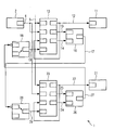
- the single FIGURE shows a block diagram with various function blocks, from which a control device 1 can be constructed.
- a control circuit not shown with a process, such as a bioreactor, serve a measuring element 2, for example, a sensor for detecting the oxygen partial pressure, and a first actuator 11, for example, a valve for adjusting the amount of air injection, and a second actuator 21, for example a stirrer with upstream speed control.
- the first actuator 11 is for generating a first manipulated variable 12, a first PID controller 13, the second actuator 21 for generating a second manipulated variable 22, a second PID controller 23 upstream.
- a set value 3 for the detected by means of the measuring element 2 control variable 4 is given, which is also supplied to both controllers 13 and 23.
- the two controllers 13 and 23 calculate a control difference which is needed internally for determining the first control variable 12 or the second control variable 22 according to the control algorithm respectively parameterized in the first controller 13 or in the second controller 23, if the respective one Controller operates in automatic mode.
- a manipulated variable limiting device In a manipulated variable limiting device, not shown in more detail, different limit values for the lower limits and the upper limits of their setting ranges are stored in the first controller 13 and in the second controller 23. If the first manipulated variable 12 of the first controller 13 reaches the lower limit value of the first manipulated variable 12, this is achieved by a high level of a Display signal 14 of a logic circuit with a first OR gate 16 is displayed. In a corresponding manner, the second controller 23 is connected to a second OR gate 26, to which display signals 24 and 25 for reaching a lower limit or an upper limit of the adjustment range of the second controller 23 are guided.
- the logical output signal 17 of the first OR element 16 is fed via a logical negation, which is symbolized by a circle, to a first input of a first selector 28.
- the negated logic signal 17 is switched through to the selector output and guided as an activation signal 29 to an input for activating the Nachrios worriess the second controller 23 at high level.
- a second logic output signal 27 is used at a position deviating from the illustrated state of a second selector 18 for generating an activation signal 19 for a tracking operation of the first controller 13.
- In the illustrated switching state of the selector 18 delivers this at its output an activation signal 19 with low level, so that the controller 13 operates as a primary controller in automatic mode.
- the first manipulated variable 12 is, in addition to its connection to the first actuator 11, guided to an input of the first controller 13 for a default value, which is output as the first manipulated variable 12 in the tracking mode.
- the first controller 13 is the primary controller which constantly operates in automatic mode.
- the second controller 23 is in follow-up mode, for example, and outputs a constant value for the second manipulated variable 22.
- the first controller 13 with its manipulated variable 12 abuts the upper or lower limit, this is done by High level on the display signal 15 and the display signal 14 is displayed and the first OR gate 16 switches via the second selector 28 a low level to the activation signal 29, so that the tracking operation of the second controller 23 is deactivated and thus to support of the first controller 13 switches to automatic mode. If the first controller 13 leaves the limitation of the setting range again, the second controller 23 goes back into tracking mode, specifically in such a way that the value of the second manipulated variable 22 output last is kept constant.
- the limit values for the respective setting range stored in the manipulated variable limiting devices of the first controller 13 and the second controller 23 may be static or alternatively variable, so that they are changed depending on the course of the process or, for example, determined by economic considerations.
- the manual mode has priority over the mode of tracking, so that in manual mode for each secondary controller a default for the constant value of the respective manipulated variable can be made.
- the respective controller Due to the reconnection of the first manipulated variable 12 or the second manipulated variable 22 to the tracking input of the first controller 13 and of the second controller 23, the respective controller remembers the value of the manipulated variable 12 or 22 last output and keeps it constant as long as the tracking mode is activated is.
- the two selectors 18 and 28 are always adjusted in opposite directions. If the second controller 23 is to be the primary controller, the selectors 18 and 28 are both set differently from the illustrated state, so that only the activation input for tracking operation of the first controller 13 is addressed, but not the corresponding activation input of the second controller 23.
- the symmetrically constructed Logic circuit consisting of the two OR gates 16, 26 and the two selectors 18, 28 makes it possible to modify during operation, the decision of which of the two controllers 13 or 23 should be the currently primary controller.
Landscapes
- Engineering & Computer Science (AREA)
- Physics & Mathematics (AREA)
- General Physics & Mathematics (AREA)
- Automation & Control Theory (AREA)
- General Engineering & Computer Science (AREA)
- Feedback Control In General (AREA)
Claims (8)
- Dispositif ( 1 ) de régulation d'un processus, dans lequel une grandeur ( 4 ) de régulation peut être influencée à l'aide de plusieurs organes ( 11, 21 ) de réglage différents, qui reposent notamment sur des principes physiques différents, caractérisé
en ce que l'on monte en amont d'un premier organe ( 11 ) de réglage un premier régulateur ( 13 ) de production d'une première grandeur ( 12 ) de réglage et d'un deuxième organe ( 21 ) de réglage, qui a le même sens d'action que le premier organe ( 11 ) de réglage, un deuxième régulateur ( 23 ) de production d'une deuxième grandeur ( 22 ) de réglage,
en ce que l'on envoie la valeur ( 3 ) de consigne et la grandeur ( 4 ) de régulation au premier et au deuxième régulateurs ( 13, 23 ),
en ce que le premier régulateur ( 13 ) se trouve comme régulateur primaire dans le fonctionnement en automatique et est pourvu d'un dispositif de limitation de grandeur de réglage ayant des valeurs limites prescrites ou pouvant l'être de la première grandeur ( 12 ) de réglage,
en ce que le deuxième régulateur ( 23 ) peut être commuté entre un fonctionnement en automatique et un fonctionnement de poursuite dans lequel il produit une valeur constante donnée à l'avance ou pouvant l'être de la deuxième grandeur ( 22 ) de réglage et
en ce qu'il y a un circuit ( 16, 26, 18, 28 ) logigue qui est constitué pour faire passer le deuxième régulateur ( 23 ) dans le fonctionnement en automatique si une valeur limite de la première grandeur ( 12 ) de réglage est atteinte et sinon pour faire passer le deuxième régulateur ( 23 ) dans le fonctionnement en poursuite. - Dispositif de régulation suivant la revendication 1, caractérisé en ce que les valeurs limites pour la première grandeur ( 12 ) de réglage peuvent être modifiées en fonction de l'état du processus ou du temps.
- Dispositif de régulation suivant la revendication 1 ou 2, caractérisé en ce que l'on envoie la deuxième grandeur ( 22 ) de réglage à une entrée du deuxième régulateur ( 23 ) pour une valeur de prescription de la grandeur de réglage dans le fonctionnement en poursuite.
- Dispositif de régulation suivant l'une des revendications précédentes, caractérisé en ce que le deuxième régulateur ( 23 ) peut être mis à la main en fonctionnement manuelle par un opérateur.
- Dispositif de régulation suivant l'une des revendications précédentes, caractérisé en ce que le deuxième régulateur ( 23 ) est pourvu d'un dispositif de limitation de la grandeur de réglage ayant des valeurs limites données à l'avance ou pouvant l'être de la deuxième grandeur ( 22 ) de réglage,
en ce que le premier régulateur ( 13 ) peut être commuté entre un fonctionnement en automatique et un fonctionnement en poursuite, dans lequel il produit une valeur constante donnée à l'avance ou pouvant l'être de la première grandeur ( 12 ) de réglage et
en ce que le circuit ( 16, 26, 18, 28 ) logique est constitué, en outre, pour faire passer le deuxième régulateur ( 23 ) en fonctionnement en automatique de manière à ce que celui-ci fonctionne en tant que régulateur primaire ainsi que pour faire passer le premier régulateur, qui ne fonctionne plus alors en régulateur primaire, dans le fonctionnement en automatique si une valeur limite de la deuxième grandeur ( 22 ) de réglage est atteinte et sinon pour faire passer le premier régulateur ( 13 ) dans le fonctionnement en poursuite. - Procédé de régulation d'un processus, dans lequel une grandeur ( 4 ) de régulation peut être influencée à l'aide de plusieurs organes ( 11, 21 ) de réglage différents, qui reposent, notamment, sur des principes physiques différents par un dispositif de régulation, dans lequel on monte, en amont d'un premier organe ( 11 ) de réglage, un premier régulateur ( 13 ) de production d'une première grandeur ( 12 ) de réglage et d'un deuxième organe ( 21 ) de réglage, qui a la même direction d'action que le premier organe ( 11 ) de réglage, un deuxième régulateur ( 23 ) de production d'une deuxième grandeur ( 22 ) de réglage, caractérisé en ce que l'on envoie la valeur ( 3 ) de consigne et la grandeur ( 4 ) de régulation au premier et au deuxième régulateurs ( 13, 23 ), en ce que le premier régulateur ( 13 ) fonctionne comme régulateur primaire dans un fonctionnement en automatique et est pourvu d'un dispositif de limitation de la grandeur de réglage ayant des valeurs limites données à l'avance ou pouvant l'être de la première grandeur ( 12 ) de réglage,
en ce que le deuxième régulateur ( 23 ) peut être commuté entre un fonctionnement en automatique et un fonctionnement en poursuite, dans lequel il produit une valeur constante donnée à l'avance ou pouvant l'être de la deuxième grandeur ( 22 ) de réglage et
en ce qu'un circuit ( 16, 26, 18, 28 ) logique met le deuxième régulateur ( 23 ) en fonctionnement en automatique si une valeur limite de la première grandeur ( 12 ) de réglage est atteinte et sinon met le deuxième régulateur ( 23 ) en fonctionnement en poursuite. - Programme d'ordinateur ayant des instructions de cote de programmes pouvant être exécuté par un ordinateur pour la mise en oeuvre du procédé suivant la revendication ( 6 ) lorsque le programme d'ordinateur est exécuté sur un ordinateur.
- Produit de programme d'ordinateur, notamment, support de données ou support de mémoires ayant un programme d'ordinateur pouvant être exécuté par un ordinateur suivant la revendication 7.
Applications Claiming Priority (1)
| Application Number | Priority Date | Filing Date | Title |
|---|---|---|---|
| PCT/EP2010/067597 WO2012065631A1 (fr) | 2010-11-16 | 2010-11-16 | Dispositif de régulation |
Publications (2)
| Publication Number | Publication Date |
|---|---|
| EP2641133A1 EP2641133A1 (fr) | 2013-09-25 |
| EP2641133B1 true EP2641133B1 (fr) | 2014-09-10 |
Family
ID=43929098
Family Applications (1)
| Application Number | Title | Priority Date | Filing Date |
|---|---|---|---|
| EP10779543.7A Active EP2641133B1 (fr) | 2010-11-16 | 2010-11-16 | Dispositif de régulation |
Country Status (4)
| Country | Link |
|---|---|
| US (1) | US9823629B2 (fr) |
| EP (1) | EP2641133B1 (fr) |
| CN (1) | CN103210356B (fr) |
| WO (1) | WO2012065631A1 (fr) |
Families Citing this family (2)
| Publication number | Priority date | Publication date | Assignee | Title |
|---|---|---|---|---|
| EP2874030A1 (fr) * | 2013-11-19 | 2015-05-20 | Siemens Aktiengesellschaft | Système d'automatisation |
| US11101638B2 (en) | 2018-10-05 | 2021-08-24 | Analog Devices Global Unlimited Company | Semiconductor die including multiple controllers for operating over an extended temperature range |
Family Cites Families (13)
| Publication number | Priority date | Publication date | Assignee | Title |
|---|---|---|---|---|
| DE2046990A1 (de) | 1970-09-24 | 1972-03-30 | Bosch Elektronik Gmbh | Regelungseinrichtung zum Konstanthalten einer elektrischen Größe |
| US4059745A (en) * | 1976-09-29 | 1977-11-22 | Fischer & Porter Co. | Override process control system |
| US4281970A (en) * | 1979-06-15 | 1981-08-04 | Phillips Petroleum Company | Turbo-expander control |
| EP0057541A1 (fr) * | 1981-01-23 | 1982-08-11 | Babcock-Bristol Limited | Un système de commande de boucle unique |
| US4769056A (en) * | 1987-03-16 | 1988-09-06 | Phillips Petroleum Company | Distillation pressure control |
| US6445231B1 (en) * | 2000-06-01 | 2002-09-03 | Micron Technology, Inc. | Digital dual-loop DLL design using coarse and fine loops |
| DE10205375A1 (de) | 2002-02-09 | 2003-08-21 | Bosch Gmbh Robert | Verfahren und Vorrichtung zur Steuerung einer Brennkraftmaschine, insbesondere zur Regelung der Drehzahl der Brennkraftmaschine |
| US6783080B2 (en) * | 2002-05-16 | 2004-08-31 | Advanced Thermal Sciences Corp. | Systems and methods for controlling temperatures of process tools |
| US7801521B2 (en) | 2005-05-18 | 2010-09-21 | Telefonaktiebolaget L M Ericsson (Publ) | System and method for communicating with aircraft through cellular base station towers |
| CN100523770C (zh) | 2006-01-12 | 2009-08-05 | 中国兵器装备集团摩托车检测技术研究所 | 摩托车自动模拟无人驾驶系统 |
| US8196310B2 (en) * | 2007-02-09 | 2012-06-12 | Usnr/Kockums Cancar Company | Method and apparatus for controlling cooling temperature and pressure in wood veneer jet dryers |
| CN100535513C (zh) * | 2007-04-29 | 2009-09-02 | 上海红箭自动化设备有限公司 | 一种锅炉水位的控制方法及其控制系统 |
| CN201546938U (zh) * | 2009-09-14 | 2010-08-11 | 福建中试所电力调整试验有限责任公司 | 变频泵自动避振控制装置 |
-
2010
- 2010-11-16 US US13/883,744 patent/US9823629B2/en active Active
- 2010-11-16 CN CN201080070060.0A patent/CN103210356B/zh active Active
- 2010-11-16 WO PCT/EP2010/067597 patent/WO2012065631A1/fr not_active Ceased
- 2010-11-16 EP EP10779543.7A patent/EP2641133B1/fr active Active
Also Published As
| Publication number | Publication date |
|---|---|
| US20140094937A1 (en) | 2014-04-03 |
| CN103210356A (zh) | 2013-07-17 |
| US9823629B2 (en) | 2017-11-21 |
| WO2012065631A1 (fr) | 2012-05-24 |
| EP2641133A1 (fr) | 2013-09-25 |
| CN103210356B (zh) | 2015-11-25 |
Similar Documents
| Publication | Publication Date | Title |
|---|---|---|
| EP2376783B2 (fr) | Procédé assisté par simulation pour la commande ou la régulation de stations d'air comprimé | |
| EP2980662B1 (fr) | Protection d'un composant d'automatisation contre des manipulations de programme par mise en correspondance de signature | |
| DE60016459T2 (de) | Verfahren und vorrichtung zur begrenzung des integralanteils in pid reglern | |
| EP3655663B1 (fr) | Procédé de réglage d'au moins deux ventilateurs | |
| EP2579112A1 (fr) | Dispositif de régulation | |
| EP3347169A1 (fr) | Procédé et système de commande d'un ensemble robotique | |
| EP2913502A1 (fr) | Procédé de fonctionnement d'un moteur à combustion couplé à un générateur et dispositif permettant de mettre en oeuvre le procédé | |
| EP4185928A1 (fr) | Autoévaluation de contrôleur de positions pour jumeau numérique | |
| EP1095319B1 (fr) | Procede pour actionner un systeme de regulation et dispositif pour mettre ledit procede en oeuvre | |
| EP2641133B1 (fr) | Dispositif de régulation | |
| DE4321604A1 (de) | Regeleinrichtung, insbesondere für einen nichtlinearen, zeitvarianten Prozeß | |
| DE3439927C2 (fr) | ||
| EP1478986B1 (fr) | Procede et dispositif pour la regulation du regime d'un moteur a combustion interne | |
| EP2288969B1 (fr) | Système de conduite d'une installation avec optimisation du modèle en plusieurs phases | |
| WO2008074736A1 (fr) | Dispositif de commande pour au moins un moteur électrique et équipé d'un régulateur coopérant avec le dispositif de commande | |
| EP3356806A1 (fr) | Installation de neutralisation | |
| EP4045982A1 (fr) | Procédé de surveillance d'au moins une partie d'un processus de production d'un système d'extrusion de film | |
| EP3825788B1 (fr) | Dispositif de réglage, système de réglage et procédé de réglage d'une grandeur physique d'un fluide | |
| EP3045675B1 (fr) | Système et procédé de réglage d'une soupape d'admission de turbine | |
| EP0590430A2 (fr) | Dispositif pour la commande automatique d'une installation de traitement basée sur la logique floue et ayant des applications préférées | |
| EP2732343B1 (fr) | Adaptation automatisée d'une régulation de centrale électrique | |
| EP0819272B1 (fr) | Appareil de programmation | |
| EP2506097B1 (fr) | Système de réglage pour la commande d'un actionneur, procédé de fonctionnement d'un actionneur et produit de programme informatique | |
| WO2003107102A1 (fr) | Systeme et procede de regulation conçus en particulier pour un processus non lineaire et variable dans le temps | |
| EP3350515B1 (fr) | Procédé et dispositif de régulation de la température d'un milieu porteur fluide |
Legal Events
| Date | Code | Title | Description |
|---|---|---|---|
| PUAI | Public reference made under article 153(3) epc to a published international application that has entered the european phase |
Free format text: ORIGINAL CODE: 0009012 |
|
| 17P | Request for examination filed |
Effective date: 20130423 |
|
| AK | Designated contracting states |
Kind code of ref document: A1 Designated state(s): AL AT BE BG CH CY CZ DE DK EE ES FI FR GB GR HR HU IE IS IT LI LT LU LV MC MK MT NL NO PL PT RO RS SE SI SK SM TR |
|
| RIN1 | Information on inventor provided before grant (corrected) |
Inventor name: LUEBBERT, ANDREAS Inventor name: KUPRIJANOV, ARTUR Inventor name: SIMUTIS, RIMVYDAS Inventor name: PFEIFFER, BERND-MARKUS Inventor name: SCHAEPE, SEBASTIAN |
|
| DAX | Request for extension of the european patent (deleted) | ||
| GRAP | Despatch of communication of intention to grant a patent |
Free format text: ORIGINAL CODE: EPIDOSNIGR1 |
|
| INTG | Intention to grant announced |
Effective date: 20140321 |
|
| GRAS | Grant fee paid |
Free format text: ORIGINAL CODE: EPIDOSNIGR3 |
|
| GRAA | (expected) grant |
Free format text: ORIGINAL CODE: 0009210 |
|
| AK | Designated contracting states |
Kind code of ref document: B1 Designated state(s): AL AT BE BG CH CY CZ DE DK EE ES FI FR GB GR HR HU IE IS IT LI LT LU LV MC MK MT NL NO PL PT RO RS SE SI SK SM TR |
|
| REG | Reference to a national code |
Ref country code: GB Ref legal event code: FG4D Free format text: NOT ENGLISH |
|
| REG | Reference to a national code |
Ref country code: CH Ref legal event code: EP |
|
| REG | Reference to a national code |
Ref country code: IE Ref legal event code: FG4D Free format text: LANGUAGE OF EP DOCUMENT: GERMAN |
|
| REG | Reference to a national code |
Ref country code: AT Ref legal event code: REF Ref document number: 686994 Country of ref document: AT Kind code of ref document: T Effective date: 20141015 |
|
| REG | Reference to a national code |
Ref country code: DE Ref legal event code: R096 Ref document number: 502010007880 Country of ref document: DE Effective date: 20141023 |
|
| PG25 | Lapsed in a contracting state [announced via postgrant information from national office to epo] |
Ref country code: FI Free format text: LAPSE BECAUSE OF FAILURE TO SUBMIT A TRANSLATION OF THE DESCRIPTION OR TO PAY THE FEE WITHIN THE PRESCRIBED TIME-LIMIT Effective date: 20140910 Ref country code: LT Free format text: LAPSE BECAUSE OF FAILURE TO SUBMIT A TRANSLATION OF THE DESCRIPTION OR TO PAY THE FEE WITHIN THE PRESCRIBED TIME-LIMIT Effective date: 20140910 Ref country code: NO Free format text: LAPSE BECAUSE OF FAILURE TO SUBMIT A TRANSLATION OF THE DESCRIPTION OR TO PAY THE FEE WITHIN THE PRESCRIBED TIME-LIMIT Effective date: 20141210 Ref country code: ES Free format text: LAPSE BECAUSE OF FAILURE TO SUBMIT A TRANSLATION OF THE DESCRIPTION OR TO PAY THE FEE WITHIN THE PRESCRIBED TIME-LIMIT Effective date: 20140910 Ref country code: GR Free format text: LAPSE BECAUSE OF FAILURE TO SUBMIT A TRANSLATION OF THE DESCRIPTION OR TO PAY THE FEE WITHIN THE PRESCRIBED TIME-LIMIT Effective date: 20141211 Ref country code: SE Free format text: LAPSE BECAUSE OF FAILURE TO SUBMIT A TRANSLATION OF THE DESCRIPTION OR TO PAY THE FEE WITHIN THE PRESCRIBED TIME-LIMIT Effective date: 20140910 |
|
| REG | Reference to a national code |
Ref country code: NL Ref legal event code: VDEP Effective date: 20140910 |
|
| REG | Reference to a national code |
Ref country code: LT Ref legal event code: MG4D |
|
| PG25 | Lapsed in a contracting state [announced via postgrant information from national office to epo] |
Ref country code: RS Free format text: LAPSE BECAUSE OF FAILURE TO SUBMIT A TRANSLATION OF THE DESCRIPTION OR TO PAY THE FEE WITHIN THE PRESCRIBED TIME-LIMIT Effective date: 20140910 Ref country code: HR Free format text: LAPSE BECAUSE OF FAILURE TO SUBMIT A TRANSLATION OF THE DESCRIPTION OR TO PAY THE FEE WITHIN THE PRESCRIBED TIME-LIMIT Effective date: 20140910 Ref country code: CY Free format text: LAPSE BECAUSE OF FAILURE TO SUBMIT A TRANSLATION OF THE DESCRIPTION OR TO PAY THE FEE WITHIN THE PRESCRIBED TIME-LIMIT Effective date: 20140910 Ref country code: LV Free format text: LAPSE BECAUSE OF FAILURE TO SUBMIT A TRANSLATION OF THE DESCRIPTION OR TO PAY THE FEE WITHIN THE PRESCRIBED TIME-LIMIT Effective date: 20140910 |
|
| PG25 | Lapsed in a contracting state [announced via postgrant information from national office to epo] |
Ref country code: NL Free format text: LAPSE BECAUSE OF FAILURE TO SUBMIT A TRANSLATION OF THE DESCRIPTION OR TO PAY THE FEE WITHIN THE PRESCRIBED TIME-LIMIT Effective date: 20140910 |
|
| PG25 | Lapsed in a contracting state [announced via postgrant information from national office to epo] |
Ref country code: CZ Free format text: LAPSE BECAUSE OF FAILURE TO SUBMIT A TRANSLATION OF THE DESCRIPTION OR TO PAY THE FEE WITHIN THE PRESCRIBED TIME-LIMIT Effective date: 20140910 Ref country code: EE Free format text: LAPSE BECAUSE OF FAILURE TO SUBMIT A TRANSLATION OF THE DESCRIPTION OR TO PAY THE FEE WITHIN THE PRESCRIBED TIME-LIMIT Effective date: 20140910 Ref country code: RO Free format text: LAPSE BECAUSE OF FAILURE TO SUBMIT A TRANSLATION OF THE DESCRIPTION OR TO PAY THE FEE WITHIN THE PRESCRIBED TIME-LIMIT Effective date: 20140910 Ref country code: SK Free format text: LAPSE BECAUSE OF FAILURE TO SUBMIT A TRANSLATION OF THE DESCRIPTION OR TO PAY THE FEE WITHIN THE PRESCRIBED TIME-LIMIT Effective date: 20140910 Ref country code: IS Free format text: LAPSE BECAUSE OF FAILURE TO SUBMIT A TRANSLATION OF THE DESCRIPTION OR TO PAY THE FEE WITHIN THE PRESCRIBED TIME-LIMIT Effective date: 20150110 Ref country code: PT Free format text: LAPSE BECAUSE OF FAILURE TO SUBMIT A TRANSLATION OF THE DESCRIPTION OR TO PAY THE FEE WITHIN THE PRESCRIBED TIME-LIMIT Effective date: 20150112 |
|
| PG25 | Lapsed in a contracting state [announced via postgrant information from national office to epo] |
Ref country code: PL Free format text: LAPSE BECAUSE OF FAILURE TO SUBMIT A TRANSLATION OF THE DESCRIPTION OR TO PAY THE FEE WITHIN THE PRESCRIBED TIME-LIMIT Effective date: 20140910 |
|
| REG | Reference to a national code |
Ref country code: DE Ref legal event code: R097 Ref document number: 502010007880 Country of ref document: DE |
|
| PG25 | Lapsed in a contracting state [announced via postgrant information from national office to epo] |
Ref country code: MC Free format text: LAPSE BECAUSE OF FAILURE TO SUBMIT A TRANSLATION OF THE DESCRIPTION OR TO PAY THE FEE WITHIN THE PRESCRIBED TIME-LIMIT Effective date: 20140910 Ref country code: BE Free format text: LAPSE BECAUSE OF NON-PAYMENT OF DUE FEES Effective date: 20141130 Ref country code: LU Free format text: LAPSE BECAUSE OF FAILURE TO SUBMIT A TRANSLATION OF THE DESCRIPTION OR TO PAY THE FEE WITHIN THE PRESCRIBED TIME-LIMIT Effective date: 20141116 |
|
| REG | Reference to a national code |
Ref country code: CH Ref legal event code: PL |
|
| PLBE | No opposition filed within time limit |
Free format text: ORIGINAL CODE: 0009261 |
|
| STAA | Information on the status of an ep patent application or granted ep patent |
Free format text: STATUS: NO OPPOSITION FILED WITHIN TIME LIMIT |
|
| PG25 | Lapsed in a contracting state [announced via postgrant information from national office to epo] |
Ref country code: DK Free format text: LAPSE BECAUSE OF FAILURE TO SUBMIT A TRANSLATION OF THE DESCRIPTION OR TO PAY THE FEE WITHIN THE PRESCRIBED TIME-LIMIT Effective date: 20140910 Ref country code: CH Free format text: LAPSE BECAUSE OF NON-PAYMENT OF DUE FEES Effective date: 20141130 Ref country code: LI Free format text: LAPSE BECAUSE OF NON-PAYMENT OF DUE FEES Effective date: 20141130 |
|
| 26N | No opposition filed |
Effective date: 20150611 |
|
| REG | Reference to a national code |
Ref country code: IE Ref legal event code: MM4A |
|
| PG25 | Lapsed in a contracting state [announced via postgrant information from national office to epo] |
Ref country code: IE Free format text: LAPSE BECAUSE OF NON-PAYMENT OF DUE FEES Effective date: 20141116 |
|
| REG | Reference to a national code |
Ref country code: FR Ref legal event code: PLFP Year of fee payment: 6 |
|
| PG25 | Lapsed in a contracting state [announced via postgrant information from national office to epo] |
Ref country code: SI Free format text: LAPSE BECAUSE OF FAILURE TO SUBMIT A TRANSLATION OF THE DESCRIPTION OR TO PAY THE FEE WITHIN THE PRESCRIBED TIME-LIMIT Effective date: 20140910 |
|
| PG25 | Lapsed in a contracting state [announced via postgrant information from national office to epo] |
Ref country code: SM Free format text: LAPSE BECAUSE OF FAILURE TO SUBMIT A TRANSLATION OF THE DESCRIPTION OR TO PAY THE FEE WITHIN THE PRESCRIBED TIME-LIMIT Effective date: 20140910 |
|
| PG25 | Lapsed in a contracting state [announced via postgrant information from national office to epo] |
Ref country code: BG Free format text: LAPSE BECAUSE OF FAILURE TO SUBMIT A TRANSLATION OF THE DESCRIPTION OR TO PAY THE FEE WITHIN THE PRESCRIBED TIME-LIMIT Effective date: 20140910 |
|
| PG25 | Lapsed in a contracting state [announced via postgrant information from national office to epo] |
Ref country code: TR Free format text: LAPSE BECAUSE OF FAILURE TO SUBMIT A TRANSLATION OF THE DESCRIPTION OR TO PAY THE FEE WITHIN THE PRESCRIBED TIME-LIMIT Effective date: 20140910 Ref country code: HU Free format text: LAPSE BECAUSE OF FAILURE TO SUBMIT A TRANSLATION OF THE DESCRIPTION OR TO PAY THE FEE WITHIN THE PRESCRIBED TIME-LIMIT; INVALID AB INITIO Effective date: 20101116 Ref country code: MT Free format text: LAPSE BECAUSE OF FAILURE TO SUBMIT A TRANSLATION OF THE DESCRIPTION OR TO PAY THE FEE WITHIN THE PRESCRIBED TIME-LIMIT Effective date: 20140910 |
|
| REG | Reference to a national code |
Ref country code: FR Ref legal event code: PLFP Year of fee payment: 7 |
|
| REG | Reference to a national code |
Ref country code: AT Ref legal event code: MM01 Ref document number: 686994 Country of ref document: AT Kind code of ref document: T Effective date: 20151116 |
|
| PG25 | Lapsed in a contracting state [announced via postgrant information from national office to epo] |
Ref country code: AT Free format text: LAPSE BECAUSE OF NON-PAYMENT OF DUE FEES Effective date: 20151116 |
|
| REG | Reference to a national code |
Ref country code: FR Ref legal event code: PLFP Year of fee payment: 8 |
|
| PG25 | Lapsed in a contracting state [announced via postgrant information from national office to epo] |
Ref country code: MK Free format text: LAPSE BECAUSE OF FAILURE TO SUBMIT A TRANSLATION OF THE DESCRIPTION OR TO PAY THE FEE WITHIN THE PRESCRIBED TIME-LIMIT Effective date: 20140910 |
|
| PG25 | Lapsed in a contracting state [announced via postgrant information from national office to epo] |
Ref country code: AL Free format text: LAPSE BECAUSE OF FAILURE TO SUBMIT A TRANSLATION OF THE DESCRIPTION OR TO PAY THE FEE WITHIN THE PRESCRIBED TIME-LIMIT Effective date: 20140910 |
|
| PGFP | Annual fee paid to national office [announced via postgrant information from national office to epo] |
Ref country code: GB Payment date: 20251211 Year of fee payment: 16 |
|
| PGFP | Annual fee paid to national office [announced via postgrant information from national office to epo] |
Ref country code: IT Payment date: 20251125 Year of fee payment: 16 |
|
| PGFP | Annual fee paid to national office [announced via postgrant information from national office to epo] |
Ref country code: FR Payment date: 20251114 Year of fee payment: 16 |
|
| PGFP | Annual fee paid to national office [announced via postgrant information from national office to epo] |
Ref country code: DE Payment date: 20260119 Year of fee payment: 16 |