EP3514059A1 - Procédé de réglage pour empêcher des différences entre les angles d'inclinaison de rotor dans un avion à rotors basculants électriques - Google Patents
Procédé de réglage pour empêcher des différences entre les angles d'inclinaison de rotor dans un avion à rotors basculants électriques Download PDFInfo
- Publication number
- EP3514059A1 EP3514059A1 EP18163674.7A EP18163674A EP3514059A1 EP 3514059 A1 EP3514059 A1 EP 3514059A1 EP 18163674 A EP18163674 A EP 18163674A EP 3514059 A1 EP3514059 A1 EP 3514059A1
- Authority
- EP
- European Patent Office
- Prior art keywords
- pylon
- command
- rate
- asymmetry
- adjusting
- Prior art date
- Legal status (The legal status is an assumption and is not a legal conclusion. Google has not performed a legal analysis and makes no representation as to the accuracy of the status listed.)
- Granted
Links
Images


Classifications
-
- B—PERFORMING OPERATIONS; TRANSPORTING
- B64—AIRCRAFT; AVIATION; COSMONAUTICS
- B64C—AEROPLANES; HELICOPTERS
- B64C13/00—Control systems or transmitting systems for actuating flying-control surfaces, lift-increasing flaps, air brakes, or spoilers
- B64C13/02—Initiating means
- B64C13/16—Initiating means actuated automatically, e.g. responsive to gust detectors
-
- B—PERFORMING OPERATIONS; TRANSPORTING
- B64—AIRCRAFT; AVIATION; COSMONAUTICS
- B64C—AEROPLANES; HELICOPTERS
- B64C13/00—Control systems or transmitting systems for actuating flying-control surfaces, lift-increasing flaps, air brakes, or spoilers
- B64C13/24—Transmitting means
- B64C13/38—Transmitting means with power amplification
- B64C13/50—Transmitting means with power amplification using electrical energy
- B64C13/503—Fly-by-Wire
-
- B—PERFORMING OPERATIONS; TRANSPORTING
- B64—AIRCRAFT; AVIATION; COSMONAUTICS
- B64C—AEROPLANES; HELICOPTERS
- B64C29/00—Aircraft capable of landing or taking-off vertically, e.g. vertical take-off and landing [VTOL] aircraft
- B64C29/0008—Aircraft capable of landing or taking-off vertically, e.g. vertical take-off and landing [VTOL] aircraft having its flight directional axis horizontal when grounded
- B64C29/0016—Aircraft capable of landing or taking-off vertically, e.g. vertical take-off and landing [VTOL] aircraft having its flight directional axis horizontal when grounded the lift during taking-off being created by free or ducted propellers or by blowers
- B64C29/0033—Aircraft capable of landing or taking-off vertically, e.g. vertical take-off and landing [VTOL] aircraft having its flight directional axis horizontal when grounded the lift during taking-off being created by free or ducted propellers or by blowers the propellers being tiltable relative to the fuselage
-
- B—PERFORMING OPERATIONS; TRANSPORTING
- B64—AIRCRAFT; AVIATION; COSMONAUTICS
- B64C—AEROPLANES; HELICOPTERS
- B64C29/00—Aircraft capable of landing or taking-off vertically, e.g. vertical take-off and landing [VTOL] aircraft
- B64C29/0008—Aircraft capable of landing or taking-off vertically, e.g. vertical take-off and landing [VTOL] aircraft having its flight directional axis horizontal when grounded
- B64C29/0041—Aircraft capable of landing or taking-off vertically, e.g. vertical take-off and landing [VTOL] aircraft having its flight directional axis horizontal when grounded the lift during taking-off being created by jet motors
- B64C29/0075—Aircraft capable of landing or taking-off vertically, e.g. vertical take-off and landing [VTOL] aircraft having its flight directional axis horizontal when grounded the lift during taking-off being created by jet motors the motors being tiltable relative to the fuselage
Definitions
- a configuration of a tiltrotor aircraft can have wing mounted nacelles or pylons that are rotated between a helicopter mode and an airplane mode.
- the right hand pylon and the left hand pylon each house a rotor system.
- a position command directed by the pilot or flight control computer and common to both the right and left pylons, directs the pylons to transition to a desired pylon angle.
- a conversion system attempts to ensure that the right pylon angle and the left pylon angle maintain the same angle to within a certain tolerance.
- Factors beyond normal flight conditions such as a degraded pylon actuator may cause sudden and/or prolonged change of load or rate capability on a pylon and result in an asymmetric condition outside of the allowed tolerance.
- Current mitigation techniques react to the detected asymmetric condition and attempt to arrest the motion of the non-degraded pylon by freezing the position command. Inherent lag in the system allows the asymmetric condition to increase before complete freezing of the pylon is achieved. Freezing of the position command itself in reaction to an asymmetric condition may prevent further asymmetry (after the lag catches up) but does not guarantee prevention of the asymmetric condition in the first place.
- Prevention of further asymmetry is accomplished by setting of conversion system brakes when a certain amount of asymmetry is detected. Once conversion system brakes are tripped, pilot troubleshooting is required to resolve the asymmetric condition before operation of the pylons can resume. Further, if the degraded condition persists, the conversion system brakes may continue to be re-activated.
- An example of a conversion system for a tiltrotor aircraft includes a first rotor system mounted to a wing member and pivotable through a range of pylon angles, a second rotor system mounted to the wing member and pivotable through the range of pylon angles, a set of actuators connected to the first rotor system and the second rotor system, a set of transducers connected to the set of actuators and a flight control computer in communication with the set of actuators and the set of transducers, the flight control computer to transmit a pylon command to the set of actuators to pivot the first rotor system and the second rotor system, and the flight control computer to transmit a first pylon command adjustment to the set of actuators when a difference between a first rotor system pylon angle and a second rotor system pylon angle exceeds a first asymmetry threshold.
- An example method for preventing a maximum asymmetric condition between a first rotor system mounted to a wing member and pivotable through a range of pylon angles and a second rotor system mounted to the wing member and pivotable through the range of pylon angles in a tiltrotor aircraft includes transmitting a pylon command and adjusting the pylon command in response to a first pylon asymmetry exceeding a first asymmetry threshold.
- An example method includes transitioning a fly-by-wire tiltrotor aircraft between an airplane mode and a helicopter mode, the tiltrotor aircraft comprising a first rotor system and a second rotor system, transmitting an original pylon command to move the first rotor system and the second rotor system, determining a difference between a first pylon angle associated with the first rotor system and a second pylon angle associated with the second rotor system, comparing the difference to an asymmetry threshold, and adjusting the original pylon command to a current pylon command if the difference exceeds the asymmetry threshold.
- Tiltrotor aircraft 100 includes fuselage 102, landing gear 104, tail member 106, wing 108, rotor system 110, and rotor system 112. While depicted as a single wing 108, it is to be understood that the wing may be formed from separate components such that two or more wing members are coupled to opposite sides of fuselage 102.
- Rotor system 110 is located on an end portion of a first side of wing 108, while rotor system 112 is located on an end portion of a second side of wing 108.
- Rotor system 110 and rotor system 112 are substantially symmetric of each other about fuselage 102.
- Rotor system 110 includes a plurality of rotor blades 114 extending from hub 116. Hub 116 is operatively connected to pylon 118. Rotor system 112 includes a plurality of rotor blades 120 extending from hub 122. Hub 122 is operatively connected to pylon 124.
- Rotor blades 114 and 120 may rotate in opposite directions to cancel the torque associated with the operation of each rotor system 110 and 112.
- the position of rotor systems 110 and 112, as well as the pitch of rotor blades 114 and 120, can be selectively controlled in order to selectively control direction, thrust, and lift of tiltrotor aircraft 100.
- rotor systems 110 and 112 are illustrated in the context of tiltrotor aircraft 100; however, rotor systems 110 and 112 can be implemented on other tiltrotor aircraft.
- tiltrotor aircraft 100 may include a quad tiltrotor that has an additional wing aft of wing 108; the additional wing can have additional rotor systems similar to rotor systems 110 and 112.
- Figure 1 illustrates tiltrotor aircraft 100 in helicopter mode, in which rotor systems 110 and 112 are positioned substantially vertical to provide a lifting thrust.
- Figure 2 illustrates tiltrotor aircraft 100 in an airplane mode, in which rotor systems 110 and 112 are positioned substantially horizontal to provide a forward thrust in which a lifting force is supplied by wing 108. It should be appreciated that tiltrotor aircraft 100 can be operated such that rotor systems 110 and 112 may be selectively positioned between airplane mode and helicopter mode, which can be referred to as a conversion mode.
- the rotor systems rotate between a generally horizontal orientation and a generally vertical orientation through a range of pylon angles.
- the positions of each rotor system can be referred to as a right pylon angle and a left pylon angle.
- the right pylon angle may differ from the left pylon angle as the rotor systems may not move through the transition between airplane mode and helicopter mode at the same rate.
- Any difference between the right pylon angle and the left pylon angle during the transition is referred to as pylon asymmetry.
- Differences between the right pylon angle and the left pylon angle due to normal flight dynamics and other aerial loads are typically accounted for in the overall design of the conversion system such that any asymmetry due to such things would be negligible and not requiring notification to the flight crew.
- tiltrotor aircraft 100 includes conversion system 300.
- Conversion system 300 monitors the pylon position of each pylon during flight and during a transition between airplane mode and helicopter mode.
- Conversion system 300 includes flight control computer 302 operatively connected to actuators 304.
- Actuators 304 are attached to pylons 306.
- Pylons 306 include both pylon 118 and pylon 124.
- Actuators 304 include a separate set of actuators connected to each pylon 118 and 124.
- Transducers 308 are connected to both flight control computer 302 and actuators 304.
- the flight control computer Based on a pylon command received from the pilot or initiated by flight control algorithms that dynamically establish necessary pylon angles based on current flight conditions, the flight control computer signals the set of actuators to impart movement on the pylons to transition the pylons between a helicopter position and an airplane position or maintain flight.
- the pylon command may be derived by a desired pylon position or a desired pylon rate.
- Conversion system 300 utilizes transducers 308 which measure the pylon angle of pylons 306. Based on the current measured pylon positions received from transducers 308 and the pylon command received from the flight crew or flight algorithms, flight control computer 302 determines a rate vector to be imparted on pylons 306 in order to move each pylon to the desired pylon position. Flight control computer 302 sends the rate vector signal to actuators 304. Actuators 304 impart a force on pylons 306 in order to move the pylons toward the desired position at the desired rate.
- each pylon is moving to a common desired position, the rate vectors on each pylon may be different since each is based on the position measurement local to each pylon and each pylon may be subject to different aerodynamic loads. Additionally, the force imparted on the pylon by the actuator will move the pylon toward the desired pylon position, but because of inertia, the pylon position can and typically will lag the pylon command.
- Desired pylon rates may range, for example, from about zero to ten degrees per second (0°-10°/sec).
- conversion system 300 prevents any resulting asymmetric condition from escalating beyond a maximum asymmetric condition.
- Maximum asymmetric conditions may range, for example, from about two to six degrees (2°-6°) depending on aircraft design and resulting flying qualities.
- a degraded pylon may be the result of hydraulic flow restrictions, electro-hydraulic valve failures, actuator deformation or bearing race contamination, or redundant conversion system actuator force fight.
- a degraded pylon does not move at the desired pylon rate. Since the non-degraded pylon is moving toward the desired pylon position at the desired pylon rate, an asymmetric condition is probable.
- Conversion system 300 monitors the difference between pylon angles and prevents maximum asymmetry from occurring.
- Adjusted pylon rate vector 402 of a non-degraded pylon is shown on X-axis 404 and Y-axis 406.
- X-axis 404 is time in seconds. Each increment of X-axis 404 may range from about 0.5 to 2.5 seconds.
- Y-axis 406 is the pylon rate vector in degrees/second. Each increment of Y-axis 406 may range from about 0.5 to 3.0 degrees/second.
- Desired pylon position command 408, adjusted pylon position command 410, measured pylon position of non degraded pylon 412, and measured pylon position of degraded pylon 414 are shown on X axis 416 and Y axis 418.
- X-axis 416 is time in seconds. Each increment of X-axis 416 may range from about 0.5 to 2.5 seconds.
- Y-axis 418 is pylon position in degrees. Each increment of Y-axis 418 may range from about three to twenty degrees.
- a maximum asymmetry threshold (“Max Asym”) 420 is the maximum allowed difference in pylon position between measured pylon position of non degraded pylon 412 and measured pylon position of degraded pylon 414 at any point in time.
- Max Asym 420 may range, for example, from about two to six degrees (2°-6°).
- the conversion system prevents the difference between the measured pylon position of the non-degraded pylon and the measured pylon position of the degraded pylon from exceeding Max Asym 420.
- the illustrative conversion system determines the difference between the pylon angles of the degraded pylon and the non-degraded pylon. Since the difference in pylon angles exceeds a predetermined asymmetry threshold, where the asymmetry threshold is a percentage of Max Asym 420, the conversion system may adjust desired pylon position command 408 to adjusted pylon position command 410 at time 424.
- the conversion system may also reduce adjusted pylon rate vector 402 by a percentage.
- the difference between the pylon angles of the degraded pylon and the non-degraded pylon begins to lessen.
- the illustrative conversion system determines the difference between the pylon angles of the degraded pylon and the non-degraded pylon. Since the difference in pylon angles has resolved to within the predetermined asymmetry threshold, the conversion system may raise adjusted pylon rate vector 402.
- the illustrative conversion system determines the difference between the pylon angles of the degraded pylon and the non-degraded pylon.
- the conversion system may adjust the adjusted pylon position command 410 at time 430.
- the conversion system may also reduce adjusted pylon rate vector 402 by a percentage.
- the conversion system may continue to monitor any differences between pylon angles until the aircraft touches down.
- conversion system 300 is activated.
- the conversion system monitors the pylon angles of pylons 118 and 124 during operation of the tiltrotor aircraft.
- the flight control computer transmits a pylon command to the actuators such that the actuators begin moving the pylons toward a desired pylon position at a desired pylon rate.
- the transducers measure the pylon angle of pylon 118 and pylon 124.
- flight control computer 302 determines the difference between the pylon angle of pylon 118 and the pylon angle of pylon 124, hereinafter referred to as pylon ⁇ .
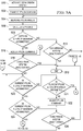
- the flight control computer compares the pylon ⁇ to a preset maximum allowable asymmetric condition Max Asym 420. If the pylon ⁇ is not greater than or equal to a first asymmetry threshold, X% of the Max Asym, then at block 510 the flight control computer determines if the conversion system has been deactivated. In an illustrative embodiment, X% may range from about 25% to 55%. If the conversion system has not been deactivated, return to block 504.
- the conversion system ends.
- the conversion system monitors any differences between pylon angles due to transitioning pylons or other aerodynamic loads until the conversion system is deactivated.
- the conversion system may be deactivated by the pilot or when the aircraft is no longer in flight.
- the flight control computer adjusts the pylon command.
- the flight control computer adjusts the pylon command by a pylon rate adjustment to B% of the desired pylon rate.
- B% may range from about 50% to 80%.
- the flight control computer adjusts the pylon command by a pylon position adjustment.
- the pylon position adjustment may be to D% of the way between the pylon command and the current measured pylon position of the pylon nearer the command. In an illustrative embodiment, D% may range from about 25-60% of the distance between the desired pylon position and the current measured pylon position.
- the flight control computer adjusts the pylon command by both a pylon rate adjustment to B% of the desired pylon rate and by a pylon position adjustment to D% of the way between the pylon command and the current measured pylon position of the pylon nearer the command. It is possible that manipulation of the pylon rate alone, even to zero, may still allow the non-degraded pylon to continue moving away from the degraded pylon to a significant degree because the actuator position is lagging the position command. Therefore, as increasing levels of asymmetry are detected, in addition to pylon rate reductions, the target pylon position can be adjusted toward or immediately changed to a point in the direction of the degraded pylon. The amount the pylon position and/or pylon rate is adjusted may be a factor of the maximum operating pylon rate, the Max Asym being prevented, how severe the degradation may be, and the peak loads that can be tolerated.
- the flight control computer determines if the conversion system has been deactivated. If the conversion system has been deactivated, return to block 512. If the conversion system has not been deactivated, proceed to block 520.
- the pylon angles are measured and if the current pylon ⁇ is not greater than or equal to X% of the Max Asym proceed to block 521.
- E% of the Max Asym proceed to block 522. In an illustrative embodiment, E% may range from about 5% to 35%.
- the flight control computer adjusts the pylon command.
- the flight control computer adjusts the pylon command by a pylon rate adjustment to 100% of the desired pylon rate. In an illustrative embodiment, the flight control computer adjusts the pylon command by a pylon position adjustment back to the desired pylon position. In an illustrative embodiment, the flight control computer adjusts the pylon command by both a pylon rate adjustment to 100% of the desired pylon rate and by a pylon position adjustment back to the desired pylon position.
- the pylon ⁇ is greater than or equal to E% of the Max Asym, return to block 518.
- the pylon ⁇ is greater than or equal to X% of the Max Asym, proceed to block 524.
- Y% of the Max Asym proceed to block 526.
- Y% may range from about 45% to 75%.
- the flight control computer determines if the conversion system has been deactivated. If the conversion system has not been deactivated, return to block 520. If the conversion system has been deactivated, return to block 512.
- the pylon ⁇ is greater than or equal to Y% of the Max Asym, proceed to block 528.
- the flight control computer adjusts the pylon command.
- the flight control computer adjusts the pylon command by a pylon rate adjustment to C% of the desired pylon rate.
- C% may range from about 20% to 50%.
- the flight control computer adjusts the pylon command by a pylon position adjustment.
- the pylon position adjustment may be to D% of the way between the current target pylon position and the current measured pylon position of the pylon nearer the command.
- the flight control computer adjusts the pylon command by both a pylon rate adjustment to C% of the desired pylon rate and by a pylon position adjustment to D% of the way between the current target pylon position and the current measured pylon position.
- the flight control computer determines if the conversion system has been deactivated. If the conversion system has been deactivated, return to block 512. If the conversion system has not been deactivated, proceed to block 532. At block 532, the pylon angles are measured and if the current pylon ⁇ is not greater than or equal to Y% of the Max Asym proceed to block 533. At block 533, if the pylon ⁇ is not greater than or equal to a recovering asymmetry threshold, X% of the Max Asym, proceed to block 534. At block 534, the flight control computer adjusts the pylon command.
- the flight control computer adjusts the pylon command by a pylon rate adjustment to B% of the desired pylon rate. In an illustrative embodiment, the flight control computer adjusts the pylon command by a pylon position adjustment to D% of the way between the desired pylon position and the current measured pylon position. In an illustrative embodiment, the flight control computer adjusts the pylon command by both a pylon rate adjustment to B% of the desired pylon rate and by a pylon position adjustment to D% of the way between the desired pylon position and the current measured pylon position.
- the flight control computer determines if the conversion system has been deactivated. If the conversion system has been deactivated, return to block 512. If the conversion system has not been deactivated, return to block 520. At block 532, if the pylon ⁇ is greater than or equal to Y% of the Max Asym, proceed to block 538.
- Z% of the Max Asym proceed to block 540.
- Z% may range from about 65% to 95%.
- the flight control computer determines if the conversion system has been deactivated. If the conversion system has not been deactivated, return to block 532. If the conversion system has been deactivated, return to block 512.
- the flight control computer adjusts the pylon command.
- the flight control computer adjusts the pylon command by a pylon rate adjustment to 0% of the desired pylon rate. In an illustrative embodiment, the flight control computer adjusts the pylon command by a pylon position adjustment. The pylon position adjustment may be to D% of the way between the current target pylon position and the current measured pylon position of the pylon nearer the current command. In an illustrative embodiment, the flight control computer adjusts the pylon command by both a pylon rate adjustment to 0% of the desired pylon rate and by a pylon position adjustment to D% of the way between the current target pylon position and the current measured pylon position.
- the flight control computer determines if the conversion system has been deactivated. If the conversion system has been deactivated, return to block 512. If the conversion system has not been deactivated, proceed to block 546. At block 546, the pylon angles are measured and if the current pylon ⁇ is not greater than or equal to Z% of the Max Asym proceed to block 547. At block 547, if the current pylon ⁇ is not greater than or equal to a recovering asymmetry threshold, Y% of the Max Asym, proceed to block 548. At block 548, the flight control computer adjusts the pylon command.
- the flight control computer adjusts the pylon command by a pylon rate adjustment C% of the desired pylon rate. In an illustrative embodiment, the flight control computer adjusts the pylon command by a pylon position adjustment to D% of the way between the current target pylon position and the current measured pylon position. In an illustrative embodiment, the flight control computer adjusts the pylon command by both a pylon rate adjustment to C% of the desired pylon rate and by a pylon position adjustment to D% of the way between the current target pylon position and the current measured pylon position.
- the flight control computer determines if the conversion system has been deactivated. If the conversion system has been deactivated, return to block 512. If the conversion system has not been deactivated, return to block 532.
- the flight control computer determines if the conversion system has been deactivated. If the conversion system has been deactivated, return to block 512. If the conversion system has not been deactivated, return to block 546.
- the pylon measurements and resulting adjustments occur in a step-wise fashion. In an illustrative embodiment, more or fewer steps may be used.
- An intentional amount of time delay could be built in to the conversion system after each incremental pylon rate and/or pylon position adjustment.
- the amount of delay may range from about 0.5 to 1.5 seconds.
- the delay between adjustments isolates minor pylon oscillations from affecting any flight dynamics algorithms and causing any further undesired dynamic interaction between the pylons.
- the delay is a minimum time to hold a pylon command adjustment as the asymmetric condition is being resolved. If the asymmetric condition is worsening, there is no delay. In some embodiments where aircraft structural modes and pylon dynamics are not a concern, delay after each pylon command adjustment may not be necessary resulting in the pylon measurements and pylon adjustments occurring more rapidly in a linear fashion.
Landscapes
- Engineering & Computer Science (AREA)
- Aviation & Aerospace Engineering (AREA)
- Automation & Control Theory (AREA)
- Control Of Position, Course, Altitude, Or Attitude Of Moving Bodies (AREA)
Applications Claiming Priority (1)
| Application Number | Priority Date | Filing Date | Title |
|---|---|---|---|
| US15/876,420 US11027821B2 (en) | 2018-01-22 | 2018-01-22 | Control method for preventing differences between rotor tilt angles in a fly-by-wire tiltrotor aircraft |
Publications (2)
| Publication Number | Publication Date |
|---|---|
| EP3514059A1 true EP3514059A1 (fr) | 2019-07-24 |
| EP3514059B1 EP3514059B1 (fr) | 2020-06-03 |
Family
ID=61768083
Family Applications (1)
| Application Number | Title | Priority Date | Filing Date |
|---|---|---|---|
| EP18163674.7A Active EP3514059B1 (fr) | 2018-01-22 | 2018-03-23 | Procédé de réglage pour empêcher des différences entre les angles d'inclinaison de rotor dans un avion à rotors basculants à commande de vol electrique |
Country Status (2)
| Country | Link |
|---|---|
| US (2) | US11027821B2 (fr) |
| EP (1) | EP3514059B1 (fr) |
Families Citing this family (7)
| Publication number | Priority date | Publication date | Assignee | Title |
|---|---|---|---|---|
| USD978719S1 (en) * | 2020-10-20 | 2023-02-21 | Guangdong Syma Model Aircraft Industrial Co., Ltd. | Aircraft toy |
| US12377974B2 (en) * | 2021-01-18 | 2025-08-05 | Textron Innovations Inc. | Pylon tracking systems for tiltrotor aircraft |
| FR3120051B1 (fr) * | 2021-02-22 | 2023-01-13 | Thales Sa | Aéronef sans équipage fiabilisé et procédé de pilotage d'un tel aéronef sans équipage |
| US12012205B2 (en) * | 2021-12-23 | 2024-06-18 | Textron Innovations Inc. | Automatic rotor tilt control |
| USD1054959S1 (en) * | 2023-03-01 | 2024-12-24 | Transcend Air Corporation | Vertical take-off and landing tilt-wing aircraft |
| USD1054960S1 (en) * | 2023-03-06 | 2024-12-24 | Transcend Air Corporation | Vertical take-off and landing tilt-wing passenger aircraft |
| WO2025217242A1 (fr) * | 2024-04-10 | 2025-10-16 | Supernal, Llc | Systèmes, procédés et dispositifs de commande d'effecteurs |
Citations (3)
| Publication number | Priority date | Publication date | Assignee | Title |
|---|---|---|---|---|
| US3514052A (en) * | 1968-01-25 | 1970-05-26 | United Aircraft Corp | Control system for aircraft having laterally offset rotors |
| WO2008111952A2 (fr) * | 2006-08-21 | 2008-09-18 | Bell Helicopter Textron Inc. | Système de gestion de défaillances d'un système de conversion pour convertible |
| US20160209290A1 (en) * | 2015-01-16 | 2016-07-21 | Bell Helicopter Textron Inc. | Dynamic center of gravity determination |
Family Cites Families (2)
| Publication number | Priority date | Publication date | Assignee | Title |
|---|---|---|---|---|
| US3592412A (en) * | 1969-10-03 | 1971-07-13 | Boeing Co | Convertible aircraft |
| US8133155B2 (en) | 2009-07-14 | 2012-03-13 | Bell Helicopter Textron Inc. | Multi-ratio rotorcraft drive system and a method of changing gear ratios thereof |
-
2018
- 2018-01-22 US US15/876,420 patent/US11027821B2/en active Active
- 2018-03-23 EP EP18163674.7A patent/EP3514059B1/fr active Active
-
2021
- 2021-05-11 US US17/317,657 patent/US11505309B2/en active Active
Patent Citations (3)
| Publication number | Priority date | Publication date | Assignee | Title |
|---|---|---|---|---|
| US3514052A (en) * | 1968-01-25 | 1970-05-26 | United Aircraft Corp | Control system for aircraft having laterally offset rotors |
| WO2008111952A2 (fr) * | 2006-08-21 | 2008-09-18 | Bell Helicopter Textron Inc. | Système de gestion de défaillances d'un système de conversion pour convertible |
| US20160209290A1 (en) * | 2015-01-16 | 2016-07-21 | Bell Helicopter Textron Inc. | Dynamic center of gravity determination |
Also Published As
| Publication number | Publication date |
|---|---|
| EP3514059B1 (fr) | 2020-06-03 |
| US20210261237A1 (en) | 2021-08-26 |
| US11027821B2 (en) | 2021-06-08 |
| US20190225322A1 (en) | 2019-07-25 |
| US11505309B2 (en) | 2022-11-22 |
Similar Documents
| Publication | Publication Date | Title |
|---|---|---|
| US11505309B2 (en) | Control method for preventing differences between rotor tilt angles in a fly-by-wire tiltrotor aircraft | |
| US10967951B2 (en) | Horizontal tail load optimization system and method | |
| RU2460670C2 (ru) | Способ и устройство для управления перестановкой подвижного стабилизатора на летательном аппарате | |
| EP3431393B1 (fr) | Systèmes de commande de battement rotor orientable pour avion à rotors basculants | |
| US9527577B2 (en) | Rotorcraft with a fuselage and at least one main rotor | |
| EP2071423B1 (fr) | Augmentation de contrôle à trajet vertical utilisant des surfaces de contrôle latéral | |
| ES2677873T3 (es) | Compensación de avance de alimentación de ráfaga longitudinal y vertical usando superficies de control laterales | |
| US9845146B2 (en) | Zoom climb prevention system for enhanced performance | |
| CN107697271A (zh) | 在电传操纵航空器系统中控制升降舵向稳定器卸载负荷 | |
| US11447240B2 (en) | Method of protecting a margin for controlling the yaw attitude of a hybrid helicopter, and a hybrid helicopter | |
| US4071209A (en) | Vehicle control system incorporating a compensator to stabilize the inherent dynamics thereof | |
| EP3617066B9 (fr) | Structure redondante résistant aux impacts | |
| KR20230089903A (ko) | 틸트프롭 항공기의 고장 시 비상착륙 방법 | |
| CN118226878A (zh) | 一种基于推力操纵的飞机应急飞行控制方法及装置 | |
| DONIGER | Some automatic landing system design considerations for scheduled operations |
Legal Events
| Date | Code | Title | Description |
|---|---|---|---|
| STAA | Information on the status of an ep patent application or granted ep patent |
Free format text: STATUS: EXAMINATION IS IN PROGRESS |
|
| PUAI | Public reference made under article 153(3) epc to a published international application that has entered the european phase |
Free format text: ORIGINAL CODE: 0009012 |
|
| 17P | Request for examination filed |
Effective date: 20180323 |
|
| AK | Designated contracting states |
Kind code of ref document: A1 Designated state(s): AL AT BE BG CH CY CZ DE DK EE ES FI FR GB GR HR HU IE IS IT LI LT LU LV MC MK MT NL NO PL PT RO RS SE SI SK SM TR |
|
| AX | Request for extension of the european patent |
Extension state: BA ME |
|
| GRAP | Despatch of communication of intention to grant a patent |
Free format text: ORIGINAL CODE: EPIDOSNIGR1 |
|
| STAA | Information on the status of an ep patent application or granted ep patent |
Free format text: STATUS: GRANT OF PATENT IS INTENDED |
|
| INTG | Intention to grant announced |
Effective date: 20191017 |
|
| RIN1 | Information on inventor provided before grant (corrected) |
Inventor name: RUCKEL, PAUL DAVID Inventor name: ATKINS, BRADY GARRETT Inventor name: TRANTHAM, MICHAEL DAVID |
|
| GRAS | Grant fee paid |
Free format text: ORIGINAL CODE: EPIDOSNIGR3 |
|
| GRAJ | Information related to disapproval of communication of intention to grant by the applicant or resumption of examination proceedings by the epo deleted |
Free format text: ORIGINAL CODE: EPIDOSDIGR1 |
|
| GRAL | Information related to payment of fee for publishing/printing deleted |
Free format text: ORIGINAL CODE: EPIDOSDIGR3 |
|
| STAA | Information on the status of an ep patent application or granted ep patent |
Free format text: STATUS: EXAMINATION IS IN PROGRESS |
|
| INTC | Intention to grant announced (deleted) | ||
| GRAR | Information related to intention to grant a patent recorded |
Free format text: ORIGINAL CODE: EPIDOSNIGR71 |
|
| STAA | Information on the status of an ep patent application or granted ep patent |
Free format text: STATUS: GRANT OF PATENT IS INTENDED |
|
| INTG | Intention to grant announced |
Effective date: 20200205 |
|
| GRAA | (expected) grant |
Free format text: ORIGINAL CODE: 0009210 |
|
| STAA | Information on the status of an ep patent application or granted ep patent |
Free format text: STATUS: THE PATENT HAS BEEN GRANTED |
|
| AK | Designated contracting states |
Kind code of ref document: B1 Designated state(s): AL AT BE BG CH CY CZ DE DK EE ES FI FR GB GR HR HU IE IS IT LI LT LU LV MC MK MT NL NO PL PT RO RS SE SI SK SM TR |
|
| REG | Reference to a national code |
Ref country code: GB Ref legal event code: FG4D |
|
| REG | Reference to a national code |
Ref country code: CH Ref legal event code: EP Ref country code: AT Ref legal event code: REF Ref document number: 1276763 Country of ref document: AT Kind code of ref document: T Effective date: 20200615 |
|
| REG | Reference to a national code |
Ref country code: DE Ref legal event code: R096 Ref document number: 602018004973 Country of ref document: DE |
|
| REG | Reference to a national code |
Ref country code: LT Ref legal event code: MG4D |
|
| PG25 | Lapsed in a contracting state [announced via postgrant information from national office to epo] |
Ref country code: FI Free format text: LAPSE BECAUSE OF FAILURE TO SUBMIT A TRANSLATION OF THE DESCRIPTION OR TO PAY THE FEE WITHIN THE PRESCRIBED TIME-LIMIT Effective date: 20200603 Ref country code: LT Free format text: LAPSE BECAUSE OF FAILURE TO SUBMIT A TRANSLATION OF THE DESCRIPTION OR TO PAY THE FEE WITHIN THE PRESCRIBED TIME-LIMIT Effective date: 20200603 Ref country code: NO Free format text: LAPSE BECAUSE OF FAILURE TO SUBMIT A TRANSLATION OF THE DESCRIPTION OR TO PAY THE FEE WITHIN THE PRESCRIBED TIME-LIMIT Effective date: 20200903 Ref country code: SE Free format text: LAPSE BECAUSE OF FAILURE TO SUBMIT A TRANSLATION OF THE DESCRIPTION OR TO PAY THE FEE WITHIN THE PRESCRIBED TIME-LIMIT Effective date: 20200603 Ref country code: GR Free format text: LAPSE BECAUSE OF FAILURE TO SUBMIT A TRANSLATION OF THE DESCRIPTION OR TO PAY THE FEE WITHIN THE PRESCRIBED TIME-LIMIT Effective date: 20200904 |
|
| REG | Reference to a national code |
Ref country code: NL Ref legal event code: MP Effective date: 20200603 |
|
| PG25 | Lapsed in a contracting state [announced via postgrant information from national office to epo] |
Ref country code: LV Free format text: LAPSE BECAUSE OF FAILURE TO SUBMIT A TRANSLATION OF THE DESCRIPTION OR TO PAY THE FEE WITHIN THE PRESCRIBED TIME-LIMIT Effective date: 20200603 Ref country code: RS Free format text: LAPSE BECAUSE OF FAILURE TO SUBMIT A TRANSLATION OF THE DESCRIPTION OR TO PAY THE FEE WITHIN THE PRESCRIBED TIME-LIMIT Effective date: 20200603 Ref country code: BG Free format text: LAPSE BECAUSE OF FAILURE TO SUBMIT A TRANSLATION OF THE DESCRIPTION OR TO PAY THE FEE WITHIN THE PRESCRIBED TIME-LIMIT Effective date: 20200903 Ref country code: HR Free format text: LAPSE BECAUSE OF FAILURE TO SUBMIT A TRANSLATION OF THE DESCRIPTION OR TO PAY THE FEE WITHIN THE PRESCRIBED TIME-LIMIT Effective date: 20200603 |
|
| REG | Reference to a national code |
Ref country code: AT Ref legal event code: MK05 Ref document number: 1276763 Country of ref document: AT Kind code of ref document: T Effective date: 20200603 |
|
| PG25 | Lapsed in a contracting state [announced via postgrant information from national office to epo] |
Ref country code: AL Free format text: LAPSE BECAUSE OF FAILURE TO SUBMIT A TRANSLATION OF THE DESCRIPTION OR TO PAY THE FEE WITHIN THE PRESCRIBED TIME-LIMIT Effective date: 20200603 Ref country code: NL Free format text: LAPSE BECAUSE OF FAILURE TO SUBMIT A TRANSLATION OF THE DESCRIPTION OR TO PAY THE FEE WITHIN THE PRESCRIBED TIME-LIMIT Effective date: 20200603 |
|
| PG25 | Lapsed in a contracting state [announced via postgrant information from national office to epo] |
Ref country code: CZ Free format text: LAPSE BECAUSE OF FAILURE TO SUBMIT A TRANSLATION OF THE DESCRIPTION OR TO PAY THE FEE WITHIN THE PRESCRIBED TIME-LIMIT Effective date: 20200603 Ref country code: ES Free format text: LAPSE BECAUSE OF FAILURE TO SUBMIT A TRANSLATION OF THE DESCRIPTION OR TO PAY THE FEE WITHIN THE PRESCRIBED TIME-LIMIT Effective date: 20200603 Ref country code: AT Free format text: LAPSE BECAUSE OF FAILURE TO SUBMIT A TRANSLATION OF THE DESCRIPTION OR TO PAY THE FEE WITHIN THE PRESCRIBED TIME-LIMIT Effective date: 20200603 Ref country code: RO Free format text: LAPSE BECAUSE OF FAILURE TO SUBMIT A TRANSLATION OF THE DESCRIPTION OR TO PAY THE FEE WITHIN THE PRESCRIBED TIME-LIMIT Effective date: 20200603 Ref country code: SM Free format text: LAPSE BECAUSE OF FAILURE TO SUBMIT A TRANSLATION OF THE DESCRIPTION OR TO PAY THE FEE WITHIN THE PRESCRIBED TIME-LIMIT Effective date: 20200603 Ref country code: EE Free format text: LAPSE BECAUSE OF FAILURE TO SUBMIT A TRANSLATION OF THE DESCRIPTION OR TO PAY THE FEE WITHIN THE PRESCRIBED TIME-LIMIT Effective date: 20200603 Ref country code: PT Free format text: LAPSE BECAUSE OF FAILURE TO SUBMIT A TRANSLATION OF THE DESCRIPTION OR TO PAY THE FEE WITHIN THE PRESCRIBED TIME-LIMIT Effective date: 20201006 |
|
| PG25 | Lapsed in a contracting state [announced via postgrant information from national office to epo] |
Ref country code: SK Free format text: LAPSE BECAUSE OF FAILURE TO SUBMIT A TRANSLATION OF THE DESCRIPTION OR TO PAY THE FEE WITHIN THE PRESCRIBED TIME-LIMIT Effective date: 20200603 Ref country code: PL Free format text: LAPSE BECAUSE OF FAILURE TO SUBMIT A TRANSLATION OF THE DESCRIPTION OR TO PAY THE FEE WITHIN THE PRESCRIBED TIME-LIMIT Effective date: 20200603 Ref country code: IS Free format text: LAPSE BECAUSE OF FAILURE TO SUBMIT A TRANSLATION OF THE DESCRIPTION OR TO PAY THE FEE WITHIN THE PRESCRIBED TIME-LIMIT Effective date: 20201003 |
|
| REG | Reference to a national code |
Ref country code: DE Ref legal event code: R097 Ref document number: 602018004973 Country of ref document: DE |
|
| PLBE | No opposition filed within time limit |
Free format text: ORIGINAL CODE: 0009261 |
|
| STAA | Information on the status of an ep patent application or granted ep patent |
Free format text: STATUS: NO OPPOSITION FILED WITHIN TIME LIMIT |
|
| PG25 | Lapsed in a contracting state [announced via postgrant information from national office to epo] |
Ref country code: DK Free format text: LAPSE BECAUSE OF FAILURE TO SUBMIT A TRANSLATION OF THE DESCRIPTION OR TO PAY THE FEE WITHIN THE PRESCRIBED TIME-LIMIT Effective date: 20200603 |
|
| 26N | No opposition filed |
Effective date: 20210304 |
|
| PG25 | Lapsed in a contracting state [announced via postgrant information from national office to epo] |
Ref country code: SI Free format text: LAPSE BECAUSE OF FAILURE TO SUBMIT A TRANSLATION OF THE DESCRIPTION OR TO PAY THE FEE WITHIN THE PRESCRIBED TIME-LIMIT Effective date: 20200603 |
|
| PG25 | Lapsed in a contracting state [announced via postgrant information from national office to epo] |
Ref country code: MC Free format text: LAPSE BECAUSE OF FAILURE TO SUBMIT A TRANSLATION OF THE DESCRIPTION OR TO PAY THE FEE WITHIN THE PRESCRIBED TIME-LIMIT Effective date: 20200603 |
|
| REG | Reference to a national code |
Ref country code: CH Ref legal event code: PL |
|
| REG | Reference to a national code |
Ref country code: BE Ref legal event code: MM Effective date: 20210331 |
|
| PG25 | Lapsed in a contracting state [announced via postgrant information from national office to epo] |
Ref country code: CH Free format text: LAPSE BECAUSE OF NON-PAYMENT OF DUE FEES Effective date: 20210331 Ref country code: LI Free format text: LAPSE BECAUSE OF NON-PAYMENT OF DUE FEES Effective date: 20210331 Ref country code: IE Free format text: LAPSE BECAUSE OF NON-PAYMENT OF DUE FEES Effective date: 20210323 Ref country code: LU Free format text: LAPSE BECAUSE OF NON-PAYMENT OF DUE FEES Effective date: 20210323 |
|
| PG25 | Lapsed in a contracting state [announced via postgrant information from national office to epo] |
Ref country code: BE Free format text: LAPSE BECAUSE OF NON-PAYMENT OF DUE FEES Effective date: 20210331 |
|
| REG | Reference to a national code |
Ref country code: GB Ref legal event code: 732E Free format text: REGISTERED BETWEEN 20220922 AND 20220928 |
|
| REG | Reference to a national code |
Ref country code: DE Ref legal event code: R081 Ref document number: 602018004973 Country of ref document: DE Owner name: TEXTRON INNOVATIONS INC., PROVIDENCE, US Free format text: FORMER OWNER: BELL HELICOPTER TEXTRON INC., FORT WORTH, TEX., US |
|
| PG25 | Lapsed in a contracting state [announced via postgrant information from national office to epo] |
Ref country code: CY Free format text: LAPSE BECAUSE OF FAILURE TO SUBMIT A TRANSLATION OF THE DESCRIPTION OR TO PAY THE FEE WITHIN THE PRESCRIBED TIME-LIMIT Effective date: 20200603 |
|
| P01 | Opt-out of the competence of the unified patent court (upc) registered |
Effective date: 20230602 |
|
| PG25 | Lapsed in a contracting state [announced via postgrant information from national office to epo] |
Ref country code: HU Free format text: LAPSE BECAUSE OF FAILURE TO SUBMIT A TRANSLATION OF THE DESCRIPTION OR TO PAY THE FEE WITHIN THE PRESCRIBED TIME-LIMIT; INVALID AB INITIO Effective date: 20180323 |
|
| PG25 | Lapsed in a contracting state [announced via postgrant information from national office to epo] |
Ref country code: MK Free format text: LAPSE BECAUSE OF FAILURE TO SUBMIT A TRANSLATION OF THE DESCRIPTION OR TO PAY THE FEE WITHIN THE PRESCRIBED TIME-LIMIT Effective date: 20200603 |
|
| PG25 | Lapsed in a contracting state [announced via postgrant information from national office to epo] |
Ref country code: TR Free format text: LAPSE BECAUSE OF FAILURE TO SUBMIT A TRANSLATION OF THE DESCRIPTION OR TO PAY THE FEE WITHIN THE PRESCRIBED TIME-LIMIT Effective date: 20200603 |
|
| PG25 | Lapsed in a contracting state [announced via postgrant information from national office to epo] |
Ref country code: MT Free format text: LAPSE BECAUSE OF FAILURE TO SUBMIT A TRANSLATION OF THE DESCRIPTION OR TO PAY THE FEE WITHIN THE PRESCRIBED TIME-LIMIT Effective date: 20200603 |
|
| PGFP | Annual fee paid to national office [announced via postgrant information from national office to epo] |
Ref country code: GB Payment date: 20260327 Year of fee payment: 9 |
|
| PGFP | Annual fee paid to national office [announced via postgrant information from national office to epo] |
Ref country code: DE Payment date: 20260327 Year of fee payment: 9 |
|
| PGFP | Annual fee paid to national office [announced via postgrant information from national office to epo] |
Ref country code: IT Payment date: 20260319 Year of fee payment: 9 |
|
| PGFP | Annual fee paid to national office [announced via postgrant information from national office to epo] |
Ref country code: FR Payment date: 20260325 Year of fee payment: 9 |