EP3514511B1 - Procédé et système permettant de déterminer le poids et le centre de gravité d'une structure - Google Patents
Procédé et système permettant de déterminer le poids et le centre de gravité d'une structure Download PDFInfo
- Publication number
- EP3514511B1 EP3514511B1 EP18382018.2A EP18382018A EP3514511B1 EP 3514511 B1 EP3514511 B1 EP 3514511B1 EP 18382018 A EP18382018 A EP 18382018A EP 3514511 B1 EP3514511 B1 EP 3514511B1
- Authority
- EP
- European Patent Office
- Prior art keywords
- sensors
- group
- calibration
- calibration sensors
- coordinate
- Prior art date
- Legal status (The legal status is an assumption and is not a legal conclusion. Google has not performed a legal analysis and makes no representation as to the accuracy of the status listed.)
- Active
Links
Images


Classifications
-
- G—PHYSICS
- G01—MEASURING; TESTING
- G01G—WEIGHING
- G01G19/00—Weighing apparatus or methods adapted for special purposes not provided for in the preceding groups
- G01G19/02—Weighing apparatus or methods adapted for special purposes not provided for in the preceding groups for weighing wheeled or rolling bodies, e.g. vehicles
- G01G19/07—Weighing apparatus or methods adapted for special purposes not provided for in the preceding groups for weighing wheeled or rolling bodies, e.g. vehicles for weighing aircraft
-
- G—PHYSICS
- G01—MEASURING; TESTING
- G01G—WEIGHING
- G01G23/00—Auxiliary devices for weighing apparatus
- G01G23/01—Testing or calibrating of weighing apparatus
-
- G—PHYSICS
- G01—MEASURING; TESTING
- G01L—MEASURING FORCE, STRESS, TORQUE, WORK, MECHANICAL POWER, MECHANICAL EFFICIENCY, OR FLUID PRESSURE
- G01L1/00—Measuring force or stress, in general
- G01L1/20—Measuring force or stress, in general by measuring variations in ohmic resistance of solid materials or of electrically-conductive fluids; by making use of electrokinetic cells, i.e. liquid-containing cells wherein an electrical potential is produced or varied upon the application of stress
- G01L1/22—Measuring force or stress, in general by measuring variations in ohmic resistance of solid materials or of electrically-conductive fluids; by making use of electrokinetic cells, i.e. liquid-containing cells wherein an electrical potential is produced or varied upon the application of stress using resistance strain gauges
- G01L1/225—Measuring circuits therefor
-
- G—PHYSICS
- G01—MEASURING; TESTING
- G01L—MEASURING FORCE, STRESS, TORQUE, WORK, MECHANICAL POWER, MECHANICAL EFFICIENCY, OR FLUID PRESSURE
- G01L25/00—Testing or calibrating of apparatus for measuring force, torque, work, mechanical power, or mechanical efficiency
-
- G—PHYSICS
- G01—MEASURING; TESTING
- G01M—TESTING STATIC OR DYNAMIC BALANCE OF MACHINES OR STRUCTURES; TESTING OF STRUCTURES OR APPARATUS, NOT OTHERWISE PROVIDED FOR
- G01M1/00—Testing static or dynamic balance of machines or structures
- G01M1/12—Static balancing; Determining position of centre of gravity
-
- G—PHYSICS
- G01—MEASURING; TESTING
- G01M—TESTING STATIC OR DYNAMIC BALANCE OF MACHINES OR STRUCTURES; TESTING OF STRUCTURES OR APPARATUS, NOT OTHERWISE PROVIDED FOR
- G01M1/00—Testing static or dynamic balance of machines or structures
- G01M1/12—Static balancing; Determining position of centre of gravity
- G01M1/122—Determining position of centre of gravity
- G01M1/125—Determining position of centre of gravity of aircraft
-
- G—PHYSICS
- G01—MEASURING; TESTING
- G01M—TESTING STATIC OR DYNAMIC BALANCE OF MACHINES OR STRUCTURES; TESTING OF STRUCTURES OR APPARATUS, NOT OTHERWISE PROVIDED FOR
- G01M5/00—Investigating the elasticity of structures, e.g. deflection of bridges or air-craft wings
- G01M5/0041—Investigating the elasticity of structures, e.g. deflection of bridges or air-craft wings by determining deflection or stress
-
- G—PHYSICS
- G06—COMPUTING OR CALCULATING; COUNTING
- G06F—ELECTRIC DIGITAL DATA PROCESSING
- G06F30/00—Computer-aided design [CAD]
- G06F30/10—Geometric CAD
- G06F30/15—Vehicle, aircraft or watercraft design
Definitions
- the present invention belongs to the field of structures and relates to a method and system for determining the weight and the centre of gravity of a structure such as a vehicle, in particular, an aircraft.
- aircrafts and other vehicles are usually weighed on scales or by lifting on jacks with load cells inside hangars.
- the cargo weight of a vehicle is usually obtained by estimation of each pallet weight when the vehicle is loaded.
- a calculus is performed to estimate the centre of gravity (C.G.) based on the estimation of the weight and the estimation of the weight positioning.
- the landing gears are the undercarriage of an aircraft which support the weight of the aircraft and are, in principle, the best place to instrument the sensors.
- landing gear structures have some disadvantages because their geometry changes with weight and is also dependent on the shock absorbers behavior, which is in turn strongly dependent on temperature, internal frictions, etc.
- the sensors installed on the landing gears support very heavy or even shock loads, which can destroy or damage the installed sensors. Therefore, these behaviors, characteristics, and geometry changes have to be taken into account by correcting the measurements obtained by the sensors. This involves complicated and time consuming calculations in order to provide an estimation of the weight and the position of the centre of gravity, the accuracy of which is not fully guaranteed.
- the United States patent application US 5,548,517 A discloses an on-board system for use in measuring, computing and displaying the gross weight and location/relocation of the centre of gravity, for aircrafts.
- the system also incorporates a software correction program, along with attached hardware, to correct and compensate for physical changes to strut components due to temperature fluctuations, seal drag and hysteresis within modern day "shock absorbing" aircraft landing gear struts.
- the system implies collecting data from several types of sensors in order to deduce the landing gear movements and changes in the geometry of the landing gear, namely pressure sensor data to obtain the telescopic strut movements, rotation sensor data to obtain the hinged movements of struts components, strain gauge data to obtain the axle deflections, etc. From all these data, a complex calculation method has to be carried out to determine the aircraft weight and the center of gravity. Moreover, because there are many factors to be considered, the accuracy of the results could be affected.
- the present invention provides a solution for the aforementioned problems, by a method for determining the weight and/or at least a first coordinate of the position of the centre of gravity of a structure according to claim 1, a system according to claim 14 and a vehicle according to claim 15.
- the present invention provides a method for determining the weight and/or at least a first coordinate of the position of the centre of gravity of a structure, the method comprising the following steps:
- constant C w and C x are real numbers.
- the present method allows determining at least one of the coordinates of the position of the centre of gravity.
- the position of the centre of gravity of a structure is defined by two coordinates. These two coordinates indicate the position of the centre of gravity on the plant (floor) of the structure, i.e. the position of the projection of the centre of gravity on the plant of the structure, or on the plant or surface on which the structure is supported. Therefore, through this entire document, the plane of projection will be understood as the plant of the structure or the plant or surface on which the structure is supported. Further, through this entire document, the first coordinate can be any of the two coordinates of the position of the centre of gravity.
- the position of the centre of gravity is defined in relation to a coordinate system, the origin of which is a predefined point.
- the X-axis is preferably selected as the projection on the horizontal plane of the longitudinal direction along the fuselage (roll axis), and the Y-axis is preferably selected as the projection on the horizontal plane of the lateral direction (pitch axis).
- the origin of the axes is located at a specified distance in front of the aircraft nose.
- a plurality of calibration sensors are installed in sensitive load points of the structure.
- a sensitive load point of a structure is to be understood as a point of the structure which suffers a substantially linear stress and/or strain in response to the weight of the structure.
- a substantially linear stress and/or strain in said sensitive load point means that the structural variation in said sensitive load point is only due to a weight loaded in the structure and the weight of the structure itself.
- the structure is loaded with different probe weights, wherein from each probe weight it is obtained a loading state.
- the first coordinate of the position of the centre of gravity and/or the weight of the structure are measured for each loading state. Measurement of the weight and the first coordinate of the position of the centre of gravity can be performed in a conventional way.
- a plurality of weighing scales is used for determining the weight and the position of the centre of gravity.
- the structure is placed on the weighing scales and the weight of the structure is determined as the addition of the weights measured by the weighing scales.
- the position of the centre of gravity is determined based on the known position of each weighing scale and on the weight measured by each weighing scale. Since a first coordinate of the position of the centre of gravity can be any of the two coordinates of the centre of gravity, any of such coordinates can be determined as described above.
- the measured response of each calibration sensor is recorded for each loading state. Once the responses of the calibration sensors and the weight and the first coordinate of the position of the centre of gravity are obtained and recorded for each loading state, then the coefficients and constants of the weight and the first coordinate of the position of the centre of gravity of the structure are respectively determined.
- the plurality of loading states in the calibration steps can be obtained by modifying the weight and/or the location of the probe weight loaded on the structure.
- each equation corresponds to a loading state and the number of equations is equal to or greater than the number of calibration sensors in the group plus one.
- the value of constant C E for calculating the first probable error may be equal to or different from the value of constant C E used for calculating the second probable error.
- the constant C E is a real and positive number. In a preferred embodiment, for calculating the first and second probable errors, the constant C E is 0.6745.
- a first group of sensors for determining the weight it is used a first group of sensors and for determining the first coordinate of the position of the centre of gravity it is used a second group of sensors.
- groups of sensors are previously determined in the calibration steps and define the first plurality of installed sensors which are located in the sensitive load points of the structure and which are used to determine at least one of the weight and the first coordinate of the centre of gravity.
- One or several of the installed sensors included in one of the groups may be included also in the other group.
- the present invention allows determining at least a first coordinate of the position of the centre of gravity and the weight based on measurements by the sensors located in at least one sensitive load point, the method increases the accuracy and the reliability of the determination of the weight and the centre of gravity.
- step ii) further comprises measuring the second coordinate of the position of the centre of gravity of the structure in each loading state:
- the value of constant C E for calculating the third probable error may be equal to or different from the values of constant C E used for calculating the first and/or the second probable error.
- the constant C E is a real and positive number. In a preferred embodiment, for calculating the first, second and third probable errors, the constant C E is 0.6745.
- constant C y is a real number.
- the calibration further comprises the steps viii') - x').
- the second coordinate of the position of the centre of gravity is also measured for each loading state. Measurement of the second coordinate of the position of the centre of gravity can be performed in a conventional way, such as using a plurality of weighing scales. The second coordinate of the position of the centre of gravity is determined based on the known position of each weighing scale and on the weight measured by each weighing scale.
- the first plurality of installed sensors includes the first group of calibration sensors selected in step vii), the second group of calibration sensors selected in step x) and the third group of calibration sensors selected in step x').
- the third group of installed sensors is used for determining the second coordinate of the position of the centre of gravity.
- These groups of installed sensors defined the first plurality of installed sensors which are located in the sensitive load points of the structure and which are used to determine the weight and/or the first and second coordinates of the position of the centre of gravity of the structure.
- One or several of the installed sensors included in one of the groups may be included in one or both of the other groups.
- the present invention allows further determining the second coordinate of the position of the centre of gravity based in measurements by the sensors installed in the at least one sensitive load point, the method increases the accuracy and the reliability of the determination of the position of the centre of gravity.
- the method comprises, after steps vii), x) and/or x'), verifying for at least one loading state i that
- the first predefined threshold, the second predefined threshold and/or the third predefined threshold is 3%, preferably 2 %.
- this additional step of verifying if the groups of calibration sensors selected fulfill such requirement allows checking the accuracy of the equations.
- the present method comprises performing the following steps prior to step a):
- the structure is loaded with the probe weights Wp i in steps of a percentage of a maximum admissible weight of the structure.
- the structure can be loaded with the 0%, 20 %, 40 %, 60%, 80 % and 100% of the probe weights Wp i .
- loading the structure in steps allows checking the linearity of the sensors.
- more than one group of calibration sensors are selected for determining the weight and/or at least one of the coordinates of the position of the centre of gravity, wherein each group of calibration sensors has an associated equation for determining the weight and/or at least one of the coordinates of the position of the centre of gravity.
- the structure is an on ground vehicle.
- the at least one sensitive load point of the structure is located in at least one bulkhead of the vehicle.
- the bulkhead of an on ground vehicle is to be understood as the area of the vehicle where the support elements are fixed.
- the support elements of the on ground vehicle are the elements on which the vehicle is seated on the ground.
- a bulkhead may be the area where such support elements are housed.
- the support elements are understood as landing gears.
- the on ground vehicle is an aircraft.
- the at least one sensitive load point is located in at least one landing gear bulkhead.
- the at least one sensitive load point is located in the nose landing gear pin.
- the at least one sensitive load point is located in the main landing gear pin.
- the landing gears are not instrumented with sensors.
- the measurements taken by the sensors are not dependent on changes in geometry nor on the shock absorbers behavior.
- the instrumentation is located in an area surrounding the landing gears or in instrumented pins receiving loads without direction changes or with very small direction changes. Instrumenting in such way there is not dependency on geometry changes neither on temperatures nor sticking influences neither other extraneous influences.
- the position of the centre of gravity and/or the weight are measured in calibration step ii) using scales and/or jacks with load cells, preferably, using three hydraulic jacks.
- the method further comprises the following steps:
- the present method In addition to determining the total weight and the position of the centre of gravity of a structure, the present method also allows determining the external forces acting on lifting surfaces of the structure. Therefore, the results of the weight and the position of the centre of gravity obtained in step b) can advantageously be corrected on the basis of said external forces acting on the lifting surfaces of the structure.
- the coordinates through which the vertical force or the vertical resultant force passes are defined in relation to the same coordinate system of the centre of gravity.
- the external forces which act on lifting surfaces are defined in relation to an axes system which will be understood as the previous coordinate system.
- the calibration steps defined for determining the weight and the position of the centre of gravity are similar to the calibration steps for determining the resultant force and the X-coordinate and the Y -coordinate through which the vertical component of the resultant force passes according to each lifting surface of the structure.
- a plurality of calibration sensors are installed in at least one lifting surface h of the structure.
- a lifting surface of a structure is to be understood as a structure body shaped to produce a normal reaction to its movement through the air.
- each equation corresponds to a loading state and the number of equations is equal to or greater than the number of calibration sensors in the group plus one.
- a fourth group of sensors For determining the vertical component of a resultant force applied on the lifting surfaces it is used a fourth group of sensors; for determining the X-coordinate through which the vertical component of the resultant force passes on the lifting surface it is used a fifth group of sensors; and for determining the Y -coordinate through which the vertical component of the resultant force passes it is used a sixth group of sensors.
- Such three groups of sensors are previously determined in the calibration steps and define the second plurality of installed sensors which are located in lifting surfaces of the structure and are used to determine a corrected weight and/or a corrected centre of gravity of the structure.
- One or several of the installed sensors included in one of the groups may be included in one or both of the other groups. In a particular embodiment wherein it is determined only one of the coordinates of the position of the centre of gravity, it is understood that the present method can correct such coordinate of the centre of gravity independently.
- the present embodiment allows determining the position of the centre of gravity and the weight considering the external forces applied on lifting surfaces based on measurements by the sensors located in at least one lifting surface, the method increases the accuracy and the reliability of the determination of the weight and the centre of gravity.
- the structure is an aircraft comprising lifting surfaces, and in step s-ii) and s-iv) of calibration steps, a plurality of probe forces are applied on the at least one lifting surface of the aircraft.
- the present invention provides a system configured for determining the weight and/or at least a first coordinate of the position of the centre of gravity of a structure, comprising:
- the data acquisition module and the data processing means may be implemented as two different elements in data communication or as a single processor.
- the present invention provides a vehicle comprising the system according to the second inventive aspect.
- the vehicle is an aircraft.
- the position of the centre of gravity is defined in relation to a coordinate system, the origin of which is a predefined point.
- the origin is located in the X-axis in front of the nose of the aircraft (6) if seen from the side, in particular at a distance of 1587 mm from the nose.
- the X-axis is selected as the projection on the horizontal plane of the longitudinal direction along the fuselage (roll axis).
- Figures 1 and 2 respectively show a main landing gear bulkhead (1) and a nose landing gear (2) of an aircraft (6).
- Selected sensitive load points (3) in the main landing gear bulkhead (1) and in pins (7) of the nose landing gear (2) are indicated in these figures.
- the sensitive load points (3) of the structure which weight and/or centre of gravity are to be determined are the points where the structure is seated on the ground.
- four of the sensitive load points (3) are located in the main landing gear bulkhead (1) and three of the sensitive load points (3) are located in the pins (7) of the nose landing gear (2), as shown in figures 1 and 2 respectively.
- the sensors (4) are strain gauge bridges.
- FIGS 3a and 3b some of the strain gauge bridges (4) installed on the structure are schematically shown.
- the strain gauge bridges (4) are attached to the structure by abrasion, adhesive application, application of pressure, and thermal curing.
- the strain gauge bridges (4) are attached to the main landing gear bulkhead (1).
- the strain gauge bridges (4) are attached to the nose landing gear pin (7).
- the sensor (4) is embedded in one of the pins (7) of the nose landing gear pins.
- Table 1A Probe weight (kg) T1 T2 T3 T4 T5 T6 T7 configuration 1 1000 1000 configuration 2 configuration 3 1000 1000 configuration 4 1000 1000 configuration 5 1000 1000 1000 configuration 6 1000 configuration 7 1000 configuration 8 1000 configuration 9 1000 1000 1000 1000 1000 1000 1000 1000 Table 1B Probe weight (kg) T8 T9 T10 T11 T12 Total Kg configuration 1 2000 configuration 2 1000 1000 2000 configuration 3 2000 configuration 4 1000 1000 4000 configuration 5 1000 4000 configuration 6 1000 1000 1000 4000 configuration 7 1000 1000 1000 4000 configuration 8 1000 2000 configuration 9 1000 1000 1000 1000 1000 10000
- the weight ( W i ) and the X-coordinate ( X i ) of the position of the centre of gravity of the aircraft (6) in each loading state i have been measured with jacks with load cells as it is schematically shown in figure 5 , wherein the load cell (10) is attached to the hydraulic jack (9) in a jacking point (11) in order to measure the real weight value ( W i ) and real X -coordinate ( X i ) of the centre of gravity of the aircraft (6) in each loading state i.
- the load cell (10) is connected to a weight indicator system (5) which registers the measures.
- Table 2A CONFIGURATION 1 six loading states Percentage of cargo Weight (N) X_CG (mm) Bridge 01 (mV/V) Bridge 02 (mV/V) Bridge 03 (mV/V) Bridge 04 (mV/V) 33% 111022.080 11117.346 -0.590 0.022 -1.503 -0.250 66% 117004.640 10835.995 -0.597 0.024 -1.518 -0.247 100% 122297.760 10614.656 -0.604 0.027 -1.542 -0.241 66% 115403.360 10948.294 -0.607 0.028 -1.549 -0.243 33% 110888.640 11164.416 -0.603 0.031 -1.570 -0.224
- Eq 2 ⁇ 72791.4 ⁇ ⁇ bridge 1 + ⁇ 75957.2 ⁇ ⁇ bridge 2 + ⁇ 65926.8 ⁇ ⁇ bridge 10 + 11083.7 ⁇ ⁇ bridge 17
- Eq 3 ⁇ 29698.7 ⁇ ⁇ bridge 3 + ⁇ 75203.4 ⁇ ⁇ bridge 9 + 24293.0 ⁇ ⁇ bridge 17 + ⁇ 25100.2 ⁇ ⁇ bridge 19
- Eq 4 ⁇ 28387.9 ⁇ ⁇ bridge 3 + ⁇ 44809.5 ⁇ ⁇ bridge 5 + ⁇ 72570.8 ⁇ ⁇ bridge 9 + 11039.6 ⁇ ⁇ bridge 17
- Eq 5 ⁇ 85744.5 ⁇ ⁇ bridge 1 + ⁇ 81280.3 ⁇ ⁇ bridge 2 + ⁇ 67149.1 ⁇ ⁇ bridge 9 + 18817.2 ⁇ ⁇ bridge 18
- Eq 6 ⁇ 80364.5 ⁇ ⁇ bridge 1 + ⁇ 57544.1 ⁇ ⁇ bridge 2 + ⁇ 67523.6 ⁇ ⁇ bridge 9 + 20592.7 ⁇ ⁇ bridge 19
- Eq 7 ⁇ 156095.0 ⁇ ⁇ bridge 1 + ⁇ 335755.3 ⁇ ⁇ bridge 2 + 181157.1 ⁇ ⁇ bridge 10 + 23123.7 ⁇ ⁇ bridge 18
- the obtained weight constant C w in the above equations is 0.
- equations 2 and 4 were selected due to their lower values for the first probable error.
- the sensors corresponding to said equations are sensors 1, 9, 10 and 17 for equation 2 and sensors 3, 5, 9 and 17 for equation 4.
- Eq 2 ⁇ 67642.3 ⁇ ⁇ bridge 1 + ⁇ 74448.0 ⁇ ⁇ bridge 2 + ⁇ 46822.8 ⁇ ⁇ bridge 11
- Eq 3 ⁇ 74227.1 ⁇ ⁇ bridge 1 + ⁇ 71078.6 ⁇ ⁇ bridge 9 + 11693.7 ⁇ ⁇ bridge 17
- Eq 4 ⁇ 42357.3 ⁇ ⁇ bridge 1 + ⁇ 132662.4 ⁇ ⁇ bridge 9 + 9092.1 ⁇ ⁇ bridge 13
- Eq 5 ⁇ 125553.4 ⁇ ⁇ bridge 1 + ⁇ 87136.1 ⁇ ⁇ bridge 7 + ⁇ 253449.0 ⁇ ⁇ bridge 10
- Eq 6 ⁇ 28267.7 ⁇ ⁇ bridge 3 + ⁇ 75931.5 ⁇ ⁇ bridge 9 + 10896.8 ⁇ ⁇ bridge 17
- equations 3 and 6 were selected due to their lower values for the probable error.
- the sensors corresponding to said equations are sensors 1, 9 and 17 for equation 3 and sensors 3, 9 and 17 for equation 6.
- At least two groups of sensors having different number of sensors are selected.
- the equations 5 and 6 were selected due to their lower values for the probable error.
- the sensors (4) corresponding to said equations are sensors 3, 10, 11 and 17 for equation 5 and sensors 3, 9, 10 and 17 for equation 4.
- the equations 1 and 4 were selected due to their lower values for the second probable error.
- the sensors (4) corresponding to said equations are sensors 3, 9 and 17 for equation 1 and sensors 1, 9 and 17 for equation 4.
- the following tables 11A-11B to 19A-19B show the estimated weight ( We i ) obtained in the calibration step vi), the subtraction of We i minus W i and the weight residual value ( ⁇ w i ) for each weight approach and each loading state i respectively.
- the weight residual value ( ⁇ w i ) has been denoted (Error W ) i .
- the following tables 20A-20B to 28A-28B show the estimate weight Xe i obtained in the calibration step ix), the subtraction of Xe i minus X i and the ( Error X ) i for each weight approach and each loading state i respectively.
- Table 20A CONFIGURATION 1 six loading states Approach 1 Approach 2 Xei (mm) Xei - Xi (mm) (Error X)i (%) Xei (mm) Xei - Xi (mm) (Error X)i (%) 11136.066 18.720 0.731 11139.023 21.677 0.846 10907.772 71.777 2.803 10908.658 72.663 2.837 10593.342 -21.314 -0.832 10594.190 -20.466 -0.799 10935.783 -12.510 -0.488 10932.669 -15.624 -0.610 11186.558 22.143 0.865 11188.943 24.527 0.958 11394.864 -29.844 -1.165 11394.086 -30.622 -1.196
- Table 20B CONFIGURATION 1 six loading states Approach 3 Approach 4 Xei Xei - Xi (Error X)i X
- this example performed on an aircraft shows that the method of the present invention provides valid estimations for the values of the weight and the X-coordinate of the position of the centre of gravity of the aircraft. Also, it has been shown that the method allows obtaining several mathematical expressions for determining the values of the weight and of the position of the centre of gravity. The fact that different mathematical expressions provide very similar results shows that the results are accurate and reliable.
Landscapes
- Physics & Mathematics (AREA)
- General Physics & Mathematics (AREA)
- Engineering & Computer Science (AREA)
- Aviation & Aerospace Engineering (AREA)
- Geometry (AREA)
- Theoretical Computer Science (AREA)
- Mathematical Optimization (AREA)
- Mathematical Analysis (AREA)
- Computational Mathematics (AREA)
- Pure & Applied Mathematics (AREA)
- Computer Hardware Design (AREA)
- Evolutionary Computation (AREA)
- General Engineering & Computer Science (AREA)
- Automation & Control Theory (AREA)
- Length Measuring Devices With Unspecified Measuring Means (AREA)
- Testing Of Devices, Machine Parts, Or Other Structures Thereof (AREA)
- Force Measurement Appropriate To Specific Purposes (AREA)
- Testing Of Balance (AREA)
Claims (15)
- Procédé de détermination du poids (W) et/ou d'au moins une première coordonnée (X) de la position du centre de gravité d'une structure, le procédé comprenant les étapes suivantes:a) mesure des réponses (µ) d'une première pluralité de capteurs installés positionnés dans des points de charge sensibles de la structure, etb) détermination du poids (W) et/ou de la première coordonnée (X) de la position du centre de gravité de la structure sur la base des réponses mesurées (µ), en tant que:

 dans lequel W est le poids de la structure, X est la première coordonnée de la position du centre de gravité de la structure sur un plan de projection, kw et kx sont des entiers naturels et µ sont les réponses mesurées par la première pluralité de capteurs installés, dans lequel l'indice dans la réponse (µ) désigne le capteur qui a réalisé le mesurage,dans lequelpour déterminer le poids (W) un premier groupe de capteurs est utilisé qui comprend un certain nombre de capteurs installés kw ,pour déterminer la première coordonnée (X) du centre de gravité un deuxième groupe de capteurs est utilisé qui comprend un certain nombre de capteurs installés kx, et dans lequeldes coefficients β jw , avec jw = 1, ... kw et γjx, avec jx = 1, ... kx, et des constantes Cw et Cx sont déterminés au préalable en appliquant les étapes d'étalonnage suivantes:i) positionner une pluralité de capteurs d'étalonnage dans des points de charge sensibles de la structure, dans lequel le nombre de capteurs d'étalonnage est m, m étant un entier naturel,ii) charger la structure avec un poids de sonde (Wpi ), obtenir un état de chargement (i) et mesurer la première coordonnée (Xi ) de la position du centre de gravité et le poids (Wi ) de la structure dans ledit état de chargement (i),iii) mesurer pour chaque capteur d'étalonnage (r) la réponse (µ r,i ) associée à l'état de chargement (i), avec r = 1, ... m, r étant un entier naturel,iv) répéter les étapes ii) et iii) pour une pluralité d'états de chargement (i), avec i = 1, ... s, s étant le nombre d'états de chargement, s étant un entier naturel,v) sélectionner des groupes d'au moins deux capteurs d'étalonnage et résoudre pour chaque groupe un système d'équations avec un nombre d'équations (P) supérieur ou égal à Nw + 1, Nw étant le nombre de capteurs d'étalonnage dans le groupe, dans lequel le système d'équations est:
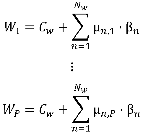 µ n,q, avec n = 1, ..., Nw, étant les réponses mesurées des capteurs d'étalonnage et Wq étant le poids associés à l'état de chargement q respectif, q = 1, ..., P,dans lequel les systèmes d'équations sont résolus par la méthode des moindres carrés, obtenant comme résultat des coefficients de poids (β n ) pour n = 1, ..., Nw, et une constante de poids (Cw ),vi) déterminer pour chaque groupe de capteurs d'étalonnage un poids estimé (Wei ) pour chaque état de chargement (i) en tant que
 vii) sélectionner un premier groupe de capteurs d'étalonnage qui satisfait au fait qu'une première erreur probable (PEw ) est minimale, dans lequel PEw est :
 viii) sélectionner des groupes d'au moins deux capteurs d'étalonnage et résoudre pour chaque groupe un système d'équations avec un nombre d'équations (P) supérieur ou égal à Nx + 1, Nx étant le nombre de capteurs d'étalonnage dans le groupe, dans lequel le système d'équations est:
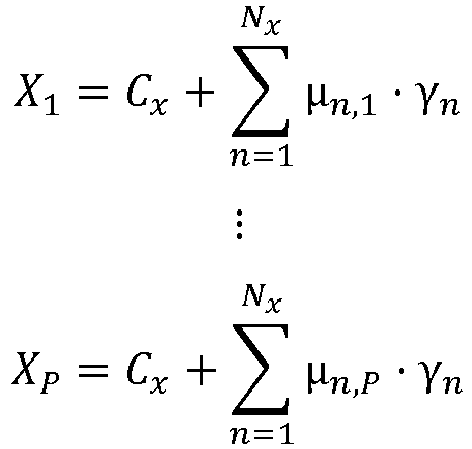 µ n,q, avec n = 1, ..., Nx, étant les réponses mesurées des capteurs d'étalonnage et Xq étant la coordonnée- X du centre de gravité associées à l'état de chargement q respectif, q = 1, ..., P,dans lequel les systèmes d'équations sont résolus par la méthode des moindres carrés, obtenant comme résultat des coefficients-X(γn ) pour n = 1, ..., Nx, et une constante-X(C x ),ix) déterminer pour chaque groupe de capteurs d'étalonnage une coordonnée-X estimée (Xei ) du centre de gravité pour chaque état de chargement (i), en tant que
 x) sélectionner un deuxième groupe de capteurs d'étalonnage qui satisfait au fait qu'une deuxième erreur probable (PEx) est minimale, dans lequel PExest:
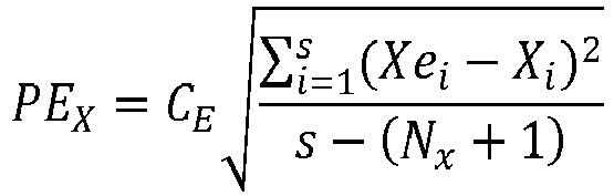 xi) sélectionner en tant que première pluralité de capteurs installés une pluralité de capteurs installés incluant:le premier groupe de capteurs d'étalonnage sélectionné à l'étape vii), etle deuxième groupe de capteurs d'étalonnage sélectionné à l'étape x),dans lequel kw est le nombre de capteurs dans le premier groupe de capteurs d'étalonnage et kx est le nombre de capteurs dans le deuxième groupe de capteurs d'étalonnage.
 - Procédé selon la revendication 1, comprenant en outre la détermination d'une seconde coordonnée (Y) de la position du centre de gravité de la structure, dans lequel la seconde coordonnée (Y) de la position du centre de gravité de la structure est déterminée sur la base des réponses mesurées (µ) de la première pluralité de capteurs installés, en tant que:

dans lequel pour déterminer la seconde coordonnée (Y) de la position du centre de gravité un troisième groupe de capteurs est utilisé qui comprend un certain nombre de capteurs installés ky, et dans lequel des coefficients-Y τjy , avec jy = 1, ... ky, et une constante-Y Cy sont déterminés au préalable en appliquant les étapes d'étalonnage suivantes au moins après les étapes i)-iv), dans lequel l'étape ii) comprend en outre le mesurage de la seconde coordonnée (Yi ) de la position du centre de gravité de la structure dans chaque état de chargement (i):viii') sélectionner des groupes d'au moins deux capteurs d'étalonnage et résoudre pour chaque groupe un système d'équations avec un nombre d'équations (P) supérieur ou égal à Ny + 1, Ny étant le nombre de capteurs d'étalonnage dans le groupe, dans lequel le système d'équations est: µ n,q, avec n = 1, ..., Ny, étant les réponses mesurées des capteurs d'étalonnage et Yq étant la coordonnée- Y du centre de gravité associées à l'état de chargement q respectif, q = 1, ..., P,dans lequel les systèmes d'équations sont résolus par la méthode des moindres carrés, obtenant comme résultat des coefficients-Y(τ n ) pour n = 1, ..., Ny, et une constante- Y(C y ),ix') déterminer pour chaque groupe de capteurs d'étalonnage une coordonnée- Y estimée (Yei ) du centre de gravité pour chaque état de chargement (i), en tant que
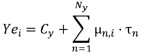 x') sélectionner un troisième groupe de capteurs d'étalonnage qui satisfait au fait qu'une troisième erreur probable (PEy ) est minimale, dans lequel PEy est:
 s étant le nombre total d'états de chargement, Ny étant le nombre de capteurs d'étalonnage dans ledit groupe de capteurs d'étalonnage, et CE étant un nombre positif réel,dans lequel la première pluralité de capteurs installés inclut en outre le troisième groupe de capteurs d'étalonnage sélectionné à l'étape x') et dans lequel ky est le nombre de capteurs dans le troisième groupe de capteurs d'étalonnage.
 - Procédé selon la revendication 2, comprenant en outre les étapes suivantes:c) mesure des réponses (µ') d'une seconde pluralité de capteurs installés positionnés dans au moins une surface portante (h) de la structure, etd) détermination d'un poids corrigé de la structure (Wcorrigé ) et/ou d'une position corrigée (Xcorrigé , Ycorrigé ) du centre de gravité de la structure en tant que:


 dans lequel W est le poids calculé de la structure, (X, Y) est la position calculée du centre de gravité de la structure,dans lequel M est le nombre de surfaces portantes prises en considération à l'étape c),dans lequel
 dans lequel


 dans lequel µ' sont les réponses mesurées par la seconde pluralité de capteurs installés, l'indice dans la réponse (µ') désignant le capteur qui a réalisé le mesurage, Lv, Lx et Ly étant des entiers naturels,dans lequel W, V' et Wcorrigé sont exprimés dans le même système d'axes ; X, X'et Xcorrigé sont exprimés selon le même système de coordonnées, et Y, Y'et Ycorrigé sont exprimés selon le même système de coordonnées,et dans lequel:pour déterminer V' un quatrième groupe de capteurs est utilisé qui comprend un certain nombre de capteurs installés Lv,pour déterminer X' un cinquième groupe de capteurs est utilisé qui comprend un certain nombre de capteurs installés Lx,pour déterminer Y' un sixième groupe de capteurs est utilisé qui comprend un certain nombre de capteurs installés Ly, et dans lequeldes coefficients
 s-i) positionner une pluralité de capteurs d'étalonnage dans au moins une surface portante (h) de la structure, dans lequel le nombre de capteurs d'étalonnage est m', m' étant un entier naturel,s-ii) appliquer une force de sonde sur la au moins une surface portante (h) de la structure, obtenir un état de force (f) et mesurer la composante verticale de la force résultante
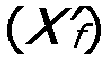

 s-iii) mesurer pour chaque capteur d'étalonnage (r) la réponse (µ'r,f ) associée à l'état de force (f), avec r = 1, ... m', r étant un entier naturel,s-iv) répéter les étapes s-ii) et s-iii) pour une pluralité d'états de force (f), avec f = 1, ... s', s' étant le nombre d'états de force, dans lequel pour chaque état de force (f) une force de sonde différente est appliquée sur la au moins une surface portante (h), s'étant un entier naturel,s-v) sélectionner des groupes d'au moins deux capteurs d'étalonnage et résoudre pour chaque groupe un système d'équations avec un nombre d'équations (P) supérieur ou égal à Nv + 1, Nv étant le nombre de capteurs d'étalonnage dans le groupe, dans lequel le système d'équations est:
 avec µn,q, avec n = 1, ..., Nv, étant les réponses mesurées des capteurs d'étalonnage et
 dans lequel les systèmes d'équations sont résolus par la méthode des moindres carrés, obtenant comme résultat des coefficients de force verticale
 s-vi) déterminer, pour chaque groupe de capteurs d'étalonnage une force verticale estimée
 s-vii) sélectionner un quatrième groupe de capteurs d'étalonnage qui satisfait au fait qu'une quatrième erreur probable

 s-viii) sélectionner des groupes d'au moins deux capteurs d'étalonnage et résoudre pour chaque groupe un système d'équations avec un nombre d'équations (P) supérieur ou égal à Nx + 1, Nx étant le nombre de capteurs d'étalonnage dans le groupe, dans lequel le système d'équations est:
 µ'n,q, avec n = 1, ..., Nx, étant les réponses mesurées des capteurs d'étalonnage et
 dans lequel les systèmes d'équations sont résolus par la méthode des moindres carrés, obtenant comme résultat des coefficients-Xγ'n pour n = 1, ..., Nx, et une constante-XC' x ,s-ix) déterminer pour chaque groupe de capteurs d'étalonnage une coordonnée-X estimée

 s-x) sélectionner un cinquième groupe de capteurs d'étalonnage qui satisfait au fait qu'une cinquième erreur probable

 s-xi) sélectionner des groupes d'au moins deux capteurs d'étalonnage et résoudre pour chaque groupe un système d'équations avec un nombre d'équations P supérieur ou égal à Ny + 1, Ny étant le nombre de capteurs d'étalonnage dans le groupe, dans lequel le système d'équations est:
 µ'n,q, avec n = 1, ..., Ny, étant les réponses mesurées des capteurs d'étalonnage et
 dans lequel les systèmes d'équations sont résolus par la méthode des moindres carrés, obtenant comme résultat des coefficients-Yτ'n pour n = 1, ..., Ny, et une constante- YC'y,s-xii) déterminer pour chaque groupe de capteurs d'étalonnage une coordonnée- Y estimée

 s-xiii) sélectionner un sixième groupe de capteurs d'étalonnage qui satisfait au fait qu'une sixième erreur probable

 s-xiv) sélectionner en tant que seconde pluralité de capteurs installés une pluralité de capteurs installés incluant:le quatrième groupe de capteurs d'étalonnage sélectionné à l'étape s-vii),le cinquième groupe de capteurs d'étalonnage sélectionné à l'étape s-x), etle sixième groupe de capteurs d'étalonnage sélectionné à l'étape s-xiii),dans lequel Lv est le nombre de capteurs dans le quatrième groupe de capteurs d'étalonnage et Lx est le nombre de capteurs dans le cinquième groupe de capteurs d'étalonnage et Ly est le nombre de capteurs dans le sixième groupe de capteurs d'étalonnage.
 - Procédé selon l'une quelconque des revendications précédentes, comprenant, après les étapes vii), x) et/ou x'), la vérification pour au moins un état de chargement i du fait que
le premier groupe de capteurs d'étalonnage satisfait au fait qu'une valeur résiduelle de poids (εwi ) est inférieure à un premier seuil prédéfini,
dans lequel
le deuxième groupe de capteurs d'étalonnage satisfait au fait qu'une valeur résiduelle de coordonnée-X(εx i) est inférieure à un deuxième seuil prédéfini,
dans lequel
dans lequel
- Procédé selon l'une quelconque des revendications précédentes, dans lequel à chaque itération de l'étape ii) la structure est chargée avec les poids de sonde Wpi , dans des étapes d'un pourcentage prédéterminé d'un poids admissible maximal de la structure.
- Procédé selon l'une quelconque des revendications précédentes, dans lequel la structure est un véhicule d'aérodrome.
- Procédé selon la revendication 6, dans lequel au moins un point de charge sensible est positionné dans au moins une cloison du véhicule.
- Procédé selon les revendications 6 ou 7 , dans lequel le véhicule d'aérodrome est un aéronef.
- Procédé selon la revendication 8, dans lequel au moins un point de charge sensible est positionné dans au moins une cloison de train d'atterrissage.
- Procédé selon l'une quelconque des revendications 8 à 9, dans lequel au moins un point de charge sensible est positionné dans la goupille du train d'aterrissage avant.
- Procédé selon l'une quelconque des revendications 8 à 10, dans lequel au moins un point de charge sensible est positionné dans la goupille du train d'aterrissage principal.
- Procédé selon l'une quelconque des revendications précédentes, dans lequel la première coordonnée (Xi ) de lacentre de gravité et/ou le poids (Wi ) est mesuré(e) à l'étape d'étalonnage ii) à l'aide d'échelles et/ou de vérins avec des cellules de charge, de préférence, à l'aide de trois vérins hydrauliques.
- Procédé selon l'une quelconque des revendications précédentes, dans lequel
à l'étape vii) une pluralité de premiers groupes de capteurs d'étalonnage sont sélectionnés, qui satisfont au fait que la première erreur probable est minimale, et/ou dans lequel
à l'étape x) une pluralité de deuxièmes groupes de capteurs d'étalonnage sont sélectionnés, qui satisfont au fait que la deuxième erreur probable est minimale, et/ou dans lequel
à l'étape x') une pluralité de troisièmes groupes de capteurs d'étalonnage sont sélectionnés, qui satisfont au fait que la troisième erreur probable est minimale. - Système configuré pour déterminer le poids (W) et/ou au moins une première coordonnée de la position du centre de gravité d'une structure, comprenant:une pluralité de capteurs installés positionnés sur la structure,un module d'acquisition de données configuré pour enregistrer des données depuis la pluralité de capteurs installés positionnés sur la structure, etun moyen de traitement de données configuré pour réaliser au moins l'étape b) du procédé selon l'une quelconque des revendications précédentes.
- Véhicule comprenant le système selon la revendication 14.
Priority Applications (5)
| Application Number | Priority Date | Filing Date | Title |
|---|---|---|---|
| ES18382018T ES2876900T3 (es) | 2018-01-17 | 2018-01-17 | Método y sistema para determinar el peso y el centro de gravedad de una estructura |
| EP18382018.2A EP3514511B1 (fr) | 2018-01-17 | 2018-01-17 | Procédé et système permettant de déterminer le poids et le centre de gravité d'une structure |
| US16/245,322 US11029191B2 (en) | 2018-01-17 | 2019-01-11 | Method and system for determining the weight and centre of gravity of a structure |
| CN201910035578.3A CN110046372B (zh) | 2018-01-17 | 2019-01-15 | 用于确定结构的重量和重心的方法和系统 |
| CA3030355A CA3030355A1 (fr) | 2018-01-17 | 2019-01-17 | Methode et systeme de determination du poids et du centre de gravite d'une structure |
Applications Claiming Priority (1)
| Application Number | Priority Date | Filing Date | Title |
|---|---|---|---|
| EP18382018.2A EP3514511B1 (fr) | 2018-01-17 | 2018-01-17 | Procédé et système permettant de déterminer le poids et le centre de gravité d'une structure |
Publications (2)
| Publication Number | Publication Date |
|---|---|
| EP3514511A1 EP3514511A1 (fr) | 2019-07-24 |
| EP3514511B1 true EP3514511B1 (fr) | 2021-03-17 |
Family
ID=61965894
Family Applications (1)
| Application Number | Title | Priority Date | Filing Date |
|---|---|---|---|
| EP18382018.2A Active EP3514511B1 (fr) | 2018-01-17 | 2018-01-17 | Procédé et système permettant de déterminer le poids et le centre de gravité d'une structure |
Country Status (5)
| Country | Link |
|---|---|
| US (1) | US11029191B2 (fr) |
| EP (1) | EP3514511B1 (fr) |
| CN (1) | CN110046372B (fr) |
| CA (1) | CA3030355A1 (fr) |
| ES (1) | ES2876900T3 (fr) |
Families Citing this family (9)
| Publication number | Priority date | Publication date | Assignee | Title |
|---|---|---|---|---|
| GB2576787B (en) * | 2018-09-03 | 2022-05-11 | Ge Aviat Systems Ltd | Measuring weight and balance and optimizing center of gravity |
| US11001392B1 (en) * | 2019-11-10 | 2021-05-11 | John Timothy Kern | System of hardware and software for determining the weight and center of gravity location of an airplane or other vehicles, like a forklift, truck, and maritime vessel |
| WO2021206970A1 (fr) * | 2020-04-07 | 2021-10-14 | MightyFly Inc. | Système et procédé de transport de paquet |
| CN111707414B (zh) * | 2020-06-23 | 2022-05-27 | 重庆大学 | 地磅式大型重型飞行器质量质心测量装置及方法 |
| JP2022035241A (ja) * | 2020-08-20 | 2022-03-04 | いすゞ自動車株式会社 | エンジンマウント方法およびエンジンマウント装置 |
| CN112560250B (zh) * | 2020-12-10 | 2024-04-09 | 中国航空工业集团公司沈阳飞机设计研究所 | 一种飞机内埋悬挂物自动占位控制方法 |
| CN114229016B (zh) * | 2021-12-17 | 2023-08-25 | 北京航空航天大学 | 一种飞机重心调节方法、系统、存储介质及电子设备 |
| JP7647637B2 (ja) * | 2022-03-14 | 2025-03-18 | トヨタ自動車株式会社 | 車両、運動マネージャ、および、運動要求補正方法 |
| CN116066924B (zh) * | 2023-01-16 | 2025-11-21 | 珠海格力电器股份有限公司 | 一种热水模块框架和两联供空调地暖机组 |
Family Cites Families (11)
| Publication number | Priority date | Publication date | Assignee | Title |
|---|---|---|---|---|
| US3210989A (en) * | 1964-01-30 | 1965-10-12 | Andrew M Samborsky | Center of gravity locating apparatus |
| WO1993016359A1 (fr) | 1992-02-07 | 1993-08-19 | Nance C Kirk | Indicateur du poids et du centre de gravite d'un avion |
| US6415242B1 (en) * | 1999-07-23 | 2002-07-02 | Abnaki Information Systems, Inc. | System for weighing fixed wing and rotary wing aircraft by the measurement of cross-axis forces |
| US7967244B2 (en) * | 2006-11-16 | 2011-06-28 | The Boeing Company | Onboard aircraft weight and balance system |
| US8060296B2 (en) * | 2008-11-12 | 2011-11-15 | Honeywell International Inc. | Low cost aircraft center of gravity monitoring systems and methods |
| KR101152861B1 (ko) * | 2010-03-02 | 2012-06-12 | 동의대학교 산학협력단 | 정적 밸런싱 측정 방법 |
| JP5733533B2 (ja) * | 2010-05-21 | 2015-06-10 | 国立大学法人東京海洋大学 | 重心検知装置 |
| DE102011004386A1 (de) * | 2011-02-18 | 2012-08-23 | Airbus Operations Gmbh | Verfahren und Vorrichtung zur Kalibrierung von Lastmesssensoren |
| US8839675B2 (en) * | 2012-04-17 | 2014-09-23 | The Boeing Company | System and method for ground vibration testing and weight and balance measurement |
| CN105067097B (zh) * | 2015-08-18 | 2017-12-22 | 中国航天空气动力技术研究院 | 可用于无人机质量测量台的多称重传感器在线标定方法 |
| CN107389266B (zh) * | 2017-08-31 | 2019-08-23 | 中国航空工业集团公司沈阳飞机设计研究所 | 一种飞行器重心柔性测量方法 |
-
2018
- 2018-01-17 EP EP18382018.2A patent/EP3514511B1/fr active Active
- 2018-01-17 ES ES18382018T patent/ES2876900T3/es active Active
-
2019
- 2019-01-11 US US16/245,322 patent/US11029191B2/en active Active
- 2019-01-15 CN CN201910035578.3A patent/CN110046372B/zh active Active
- 2019-01-17 CA CA3030355A patent/CA3030355A1/fr active Pending
Non-Patent Citations (1)
| Title |
|---|
| None * |
Also Published As
| Publication number | Publication date |
|---|---|
| EP3514511A1 (fr) | 2019-07-24 |
| CN110046372B (zh) | 2025-02-25 |
| CA3030355A1 (fr) | 2019-07-17 |
| ES2876900T3 (es) | 2021-11-15 |
| US11029191B2 (en) | 2021-06-08 |
| CN110046372A (zh) | 2019-07-23 |
| US20190219437A1 (en) | 2019-07-18 |
Similar Documents
| Publication | Publication Date | Title |
|---|---|---|
| EP3514511B1 (fr) | Procédé et système permettant de déterminer le poids et le centre de gravité d'une structure | |
| US8060296B2 (en) | Low cost aircraft center of gravity monitoring systems and methods | |
| US10899435B2 (en) | Systems and methods for detecting landing gear ground loads | |
| CN109733638B (zh) | 一种长支柱起落架大变形情况下载荷施加方法 | |
| KR101478760B1 (ko) | 차량의 가동축 하중 측정장치 및 하중 측정방법 | |
| Nitsche et al. | Measurement uncertainty evaluation of a hexapod-structured calibration device for multi-component force and moment sensors | |
| CA2665963C (fr) | Systeme embarque de centrage d'aeronef | |
| JP5995635B2 (ja) | 多分力計測方法 | |
| Reis et al. | Calibration uncertainty estimation of a strain-gage external balance | |
| JP5259928B2 (ja) | 航空機の重量および/または重心位置を求める装置および方法 | |
| US3488997A (en) | Weight and center of gravity indication system | |
| CN117360716A (zh) | 基于目标值的邮轮整船有限元分析方法 | |
| Zhang et al. | Mechanical analysis of normal force interference on axial force measurement for internal sting balance | |
| CN116499882A (zh) | 一种建筑物的压力测量方法及设备 | |
| Nikitenko | Evaluation of elements loading in the metal structures of powered support units | |
| Poddaeva | Result verification for numerical modeling of wind effects on unique buildings and structures | |
| CN114486302B (zh) | 考虑纵向加载附加弯矩的车钩力测量方法及系统 | |
| CN109918842A (zh) | 撬杠施加起落架载荷的修正方法 | |
| Bogatyrev et al. | Technology for calibration of measuring instruments of samsat nanosatellites' family | |
| JPH01267429A (ja) | 多分力の計測方法 | |
| CN109866941A (zh) | 起落架大变形随动加载过程中载荷准确施加方法 | |
| ISGANDAROVA | METROLOGICAL MODELING METHOD FOR CALIBRATION OF AIRCRAFT WEIGHING AND CENTERING SYSTEMS | |
| CN120949131B (zh) | 一种飞行器航磁补偿方法、系统、设备和介质 | |
| Kammeyer et al. | Estimation of the uncertainty in internal balance calibration through comprehensive error propagation | |
| CN119475552B (zh) | 一种起落架的剩余寿命实时计算方法及装置 |
Legal Events
| Date | Code | Title | Description |
|---|---|---|---|
| PUAI | Public reference made under article 153(3) epc to a published international application that has entered the european phase |
Free format text: ORIGINAL CODE: 0009012 |
|
| STAA | Information on the status of an ep patent application or granted ep patent |
Free format text: STATUS: THE APPLICATION HAS BEEN PUBLISHED |
|
| AK | Designated contracting states |
Kind code of ref document: A1 Designated state(s): AL AT BE BG CH CY CZ DE DK EE ES FI FR GB GR HR HU IE IS IT LI LT LU LV MC MK MT NL NO PL PT RO RS SE SI SK SM TR |
|
| AX | Request for extension of the european patent |
Extension state: BA ME |
|
| STAA | Information on the status of an ep patent application or granted ep patent |
Free format text: STATUS: REQUEST FOR EXAMINATION WAS MADE |
|
| 17P | Request for examination filed |
Effective date: 20191219 |
|
| RBV | Designated contracting states (corrected) |
Designated state(s): AL AT BE BG CH CY CZ DE DK EE ES FI FR GB GR HR HU IE IS IT LI LT LU LV MC MK MT NL NO PL PT RO RS SE SI SK SM TR |
|
| GRAP | Despatch of communication of intention to grant a patent |
Free format text: ORIGINAL CODE: EPIDOSNIGR1 |
|
| STAA | Information on the status of an ep patent application or granted ep patent |
Free format text: STATUS: GRANT OF PATENT IS INTENDED |
|
| INTG | Intention to grant announced |
Effective date: 20200402 |
|
| GRAS | Grant fee paid |
Free format text: ORIGINAL CODE: EPIDOSNIGR3 |
|
| GRAJ | Information related to disapproval of communication of intention to grant by the applicant or resumption of examination proceedings by the epo deleted |
Free format text: ORIGINAL CODE: EPIDOSDIGR1 |
|
| GRAL | Information related to payment of fee for publishing/printing deleted |
Free format text: ORIGINAL CODE: EPIDOSDIGR3 |
|
| STAA | Information on the status of an ep patent application or granted ep patent |
Free format text: STATUS: REQUEST FOR EXAMINATION WAS MADE |
|
| INTC | Intention to grant announced (deleted) | ||
| GRAP | Despatch of communication of intention to grant a patent |
Free format text: ORIGINAL CODE: EPIDOSNIGR1 |
|
| STAA | Information on the status of an ep patent application or granted ep patent |
Free format text: STATUS: GRANT OF PATENT IS INTENDED |
|
| INTG | Intention to grant announced |
Effective date: 20201020 |
|
| GRAA | (expected) grant |
Free format text: ORIGINAL CODE: 0009210 |
|
| STAA | Information on the status of an ep patent application or granted ep patent |
Free format text: STATUS: THE PATENT HAS BEEN GRANTED |
|
| AK | Designated contracting states |
Kind code of ref document: B1 Designated state(s): AL AT BE BG CH CY CZ DE DK EE ES FI FR GB GR HR HU IE IS IT LI LT LU LV MC MK MT NL NO PL PT RO RS SE SI SK SM TR |
|
| REG | Reference to a national code |
Ref country code: GB Ref legal event code: FG4D |
|
| REG | Reference to a national code |
Ref country code: CH Ref legal event code: EP |
|
| REG | Reference to a national code |
Ref country code: DE Ref legal event code: R096 Ref document number: 602018014029 Country of ref document: DE |
|
| REG | Reference to a national code |
Ref country code: IE Ref legal event code: FG4D |
|
| REG | Reference to a national code |
Ref country code: AT Ref legal event code: REF Ref document number: 1372664 Country of ref document: AT Kind code of ref document: T Effective date: 20210415 |
|
| REG | Reference to a national code |
Ref country code: LT Ref legal event code: MG9D |
|
| PG25 | Lapsed in a contracting state [announced via postgrant information from national office to epo] |
Ref country code: BG Free format text: LAPSE BECAUSE OF FAILURE TO SUBMIT A TRANSLATION OF THE DESCRIPTION OR TO PAY THE FEE WITHIN THE PRESCRIBED TIME-LIMIT Effective date: 20210617 Ref country code: GR Free format text: LAPSE BECAUSE OF FAILURE TO SUBMIT A TRANSLATION OF THE DESCRIPTION OR TO PAY THE FEE WITHIN THE PRESCRIBED TIME-LIMIT Effective date: 20210618 Ref country code: FI Free format text: LAPSE BECAUSE OF FAILURE TO SUBMIT A TRANSLATION OF THE DESCRIPTION OR TO PAY THE FEE WITHIN THE PRESCRIBED TIME-LIMIT Effective date: 20210317 Ref country code: HR Free format text: LAPSE BECAUSE OF FAILURE TO SUBMIT A TRANSLATION OF THE DESCRIPTION OR TO PAY THE FEE WITHIN THE PRESCRIBED TIME-LIMIT Effective date: 20210317 Ref country code: NO Free format text: LAPSE BECAUSE OF FAILURE TO SUBMIT A TRANSLATION OF THE DESCRIPTION OR TO PAY THE FEE WITHIN THE PRESCRIBED TIME-LIMIT Effective date: 20210617 |
|
| REG | Reference to a national code |
Ref country code: AT Ref legal event code: MK05 Ref document number: 1372664 Country of ref document: AT Kind code of ref document: T Effective date: 20210317 |
|
| REG | Reference to a national code |
Ref country code: NL Ref legal event code: MP Effective date: 20210317 |
|
| PG25 | Lapsed in a contracting state [announced via postgrant information from national office to epo] |
Ref country code: SE Free format text: LAPSE BECAUSE OF FAILURE TO SUBMIT A TRANSLATION OF THE DESCRIPTION OR TO PAY THE FEE WITHIN THE PRESCRIBED TIME-LIMIT Effective date: 20210317 Ref country code: RS Free format text: LAPSE BECAUSE OF FAILURE TO SUBMIT A TRANSLATION OF THE DESCRIPTION OR TO PAY THE FEE WITHIN THE PRESCRIBED TIME-LIMIT Effective date: 20210317 Ref country code: LV Free format text: LAPSE BECAUSE OF FAILURE TO SUBMIT A TRANSLATION OF THE DESCRIPTION OR TO PAY THE FEE WITHIN THE PRESCRIBED TIME-LIMIT Effective date: 20210317 |
|
| PG25 | Lapsed in a contracting state [announced via postgrant information from national office to epo] |
Ref country code: NL Free format text: LAPSE BECAUSE OF FAILURE TO SUBMIT A TRANSLATION OF THE DESCRIPTION OR TO PAY THE FEE WITHIN THE PRESCRIBED TIME-LIMIT Effective date: 20210317 |
|
| PG25 | Lapsed in a contracting state [announced via postgrant information from national office to epo] |
Ref country code: AT Free format text: LAPSE BECAUSE OF FAILURE TO SUBMIT A TRANSLATION OF THE DESCRIPTION OR TO PAY THE FEE WITHIN THE PRESCRIBED TIME-LIMIT Effective date: 20210317 Ref country code: SM Free format text: LAPSE BECAUSE OF FAILURE TO SUBMIT A TRANSLATION OF THE DESCRIPTION OR TO PAY THE FEE WITHIN THE PRESCRIBED TIME-LIMIT Effective date: 20210317 Ref country code: LT Free format text: LAPSE BECAUSE OF FAILURE TO SUBMIT A TRANSLATION OF THE DESCRIPTION OR TO PAY THE FEE WITHIN THE PRESCRIBED TIME-LIMIT Effective date: 20210317 Ref country code: CZ Free format text: LAPSE BECAUSE OF FAILURE TO SUBMIT A TRANSLATION OF THE DESCRIPTION OR TO PAY THE FEE WITHIN THE PRESCRIBED TIME-LIMIT Effective date: 20210317 Ref country code: EE Free format text: LAPSE BECAUSE OF FAILURE TO SUBMIT A TRANSLATION OF THE DESCRIPTION OR TO PAY THE FEE WITHIN THE PRESCRIBED TIME-LIMIT Effective date: 20210317 |
|
| REG | Reference to a national code |
Ref country code: ES Ref legal event code: FG2A Ref document number: 2876900 Country of ref document: ES Kind code of ref document: T3 Effective date: 20211115 |
|
| PG25 | Lapsed in a contracting state [announced via postgrant information from national office to epo] |
Ref country code: SK Free format text: LAPSE BECAUSE OF FAILURE TO SUBMIT A TRANSLATION OF THE DESCRIPTION OR TO PAY THE FEE WITHIN THE PRESCRIBED TIME-LIMIT Effective date: 20210317 Ref country code: RO Free format text: LAPSE BECAUSE OF FAILURE TO SUBMIT A TRANSLATION OF THE DESCRIPTION OR TO PAY THE FEE WITHIN THE PRESCRIBED TIME-LIMIT Effective date: 20210317 Ref country code: PT Free format text: LAPSE BECAUSE OF FAILURE TO SUBMIT A TRANSLATION OF THE DESCRIPTION OR TO PAY THE FEE WITHIN THE PRESCRIBED TIME-LIMIT Effective date: 20210719 Ref country code: PL Free format text: LAPSE BECAUSE OF FAILURE TO SUBMIT A TRANSLATION OF THE DESCRIPTION OR TO PAY THE FEE WITHIN THE PRESCRIBED TIME-LIMIT Effective date: 20210317 Ref country code: IS Free format text: LAPSE BECAUSE OF FAILURE TO SUBMIT A TRANSLATION OF THE DESCRIPTION OR TO PAY THE FEE WITHIN THE PRESCRIBED TIME-LIMIT Effective date: 20210717 |
|
| REG | Reference to a national code |
Ref country code: DE Ref legal event code: R097 Ref document number: 602018014029 Country of ref document: DE |
|
| PLBE | No opposition filed within time limit |
Free format text: ORIGINAL CODE: 0009261 |
|
| STAA | Information on the status of an ep patent application or granted ep patent |
Free format text: STATUS: NO OPPOSITION FILED WITHIN TIME LIMIT |
|
| PG25 | Lapsed in a contracting state [announced via postgrant information from national office to epo] |
Ref country code: DK Free format text: LAPSE BECAUSE OF FAILURE TO SUBMIT A TRANSLATION OF THE DESCRIPTION OR TO PAY THE FEE WITHIN THE PRESCRIBED TIME-LIMIT Effective date: 20210317 Ref country code: AL Free format text: LAPSE BECAUSE OF FAILURE TO SUBMIT A TRANSLATION OF THE DESCRIPTION OR TO PAY THE FEE WITHIN THE PRESCRIBED TIME-LIMIT Effective date: 20210317 |
|
| 26N | No opposition filed |
Effective date: 20211220 |
|
| PG25 | Lapsed in a contracting state [announced via postgrant information from national office to epo] |
Ref country code: SI Free format text: LAPSE BECAUSE OF FAILURE TO SUBMIT A TRANSLATION OF THE DESCRIPTION OR TO PAY THE FEE WITHIN THE PRESCRIBED TIME-LIMIT Effective date: 20210317 |
|
| PG25 | Lapsed in a contracting state [announced via postgrant information from national office to epo] |
Ref country code: IT Free format text: LAPSE BECAUSE OF FAILURE TO SUBMIT A TRANSLATION OF THE DESCRIPTION OR TO PAY THE FEE WITHIN THE PRESCRIBED TIME-LIMIT Effective date: 20210317 |
|
| PG25 | Lapsed in a contracting state [announced via postgrant information from national office to epo] |
Ref country code: IS Free format text: LAPSE BECAUSE OF FAILURE TO SUBMIT A TRANSLATION OF THE DESCRIPTION OR TO PAY THE FEE WITHIN THE PRESCRIBED TIME-LIMIT Effective date: 20210717 |
|
| PG25 | Lapsed in a contracting state [announced via postgrant information from national office to epo] |
Ref country code: MC Free format text: LAPSE BECAUSE OF FAILURE TO SUBMIT A TRANSLATION OF THE DESCRIPTION OR TO PAY THE FEE WITHIN THE PRESCRIBED TIME-LIMIT Effective date: 20210317 |
|
| REG | Reference to a national code |
Ref country code: CH Ref legal event code: PL |
|
| REG | Reference to a national code |
Ref country code: BE Ref legal event code: MM Effective date: 20220131 |
|
| PG25 | Lapsed in a contracting state [announced via postgrant information from national office to epo] |
Ref country code: LU Free format text: LAPSE BECAUSE OF NON-PAYMENT OF DUE FEES Effective date: 20220117 |
|
| PG25 | Lapsed in a contracting state [announced via postgrant information from national office to epo] |
Ref country code: BE Free format text: LAPSE BECAUSE OF NON-PAYMENT OF DUE FEES Effective date: 20220131 |
|
| PG25 | Lapsed in a contracting state [announced via postgrant information from national office to epo] |
Ref country code: LI Free format text: LAPSE BECAUSE OF NON-PAYMENT OF DUE FEES Effective date: 20220131 Ref country code: CH Free format text: LAPSE BECAUSE OF NON-PAYMENT OF DUE FEES Effective date: 20220131 |
|
| PG25 | Lapsed in a contracting state [announced via postgrant information from national office to epo] |
Ref country code: IE Free format text: LAPSE BECAUSE OF NON-PAYMENT OF DUE FEES Effective date: 20220117 |
|
| PG25 | Lapsed in a contracting state [announced via postgrant information from national office to epo] |
Ref country code: MK Free format text: LAPSE BECAUSE OF FAILURE TO SUBMIT A TRANSLATION OF THE DESCRIPTION OR TO PAY THE FEE WITHIN THE PRESCRIBED TIME-LIMIT Effective date: 20210317 Ref country code: CY Free format text: LAPSE BECAUSE OF FAILURE TO SUBMIT A TRANSLATION OF THE DESCRIPTION OR TO PAY THE FEE WITHIN THE PRESCRIBED TIME-LIMIT Effective date: 20210317 |
|
| PG25 | Lapsed in a contracting state [announced via postgrant information from national office to epo] |
Ref country code: HU Free format text: LAPSE BECAUSE OF FAILURE TO SUBMIT A TRANSLATION OF THE DESCRIPTION OR TO PAY THE FEE WITHIN THE PRESCRIBED TIME-LIMIT; INVALID AB INITIO Effective date: 20180117 |
|
| PG25 | Lapsed in a contracting state [announced via postgrant information from national office to epo] |
Ref country code: TR Free format text: LAPSE BECAUSE OF FAILURE TO SUBMIT A TRANSLATION OF THE DESCRIPTION OR TO PAY THE FEE WITHIN THE PRESCRIBED TIME-LIMIT Effective date: 20210317 |
|
| PG25 | Lapsed in a contracting state [announced via postgrant information from national office to epo] |
Ref country code: MT Free format text: LAPSE BECAUSE OF FAILURE TO SUBMIT A TRANSLATION OF THE DESCRIPTION OR TO PAY THE FEE WITHIN THE PRESCRIBED TIME-LIMIT Effective date: 20210317 |
|
| PGFP | Annual fee paid to national office [announced via postgrant information from national office to epo] |
Ref country code: GB Payment date: 20260123 Year of fee payment: 9 |
|
| PGFP | Annual fee paid to national office [announced via postgrant information from national office to epo] |
Ref country code: ES Payment date: 20260227 Year of fee payment: 9 |
|
| PGFP | Annual fee paid to national office [announced via postgrant information from national office to epo] |
Ref country code: DE Payment date: 20260121 Year of fee payment: 9 |
|
| PGFP | Annual fee paid to national office [announced via postgrant information from national office to epo] |
Ref country code: FR Payment date: 20260123 Year of fee payment: 9 |