EP3514582A2 - Rétroréflecteur élastique - Google Patents
Rétroréflecteur élastique Download PDFInfo
- Publication number
- EP3514582A2 EP3514582A2 EP18210406.7A EP18210406A EP3514582A2 EP 3514582 A2 EP3514582 A2 EP 3514582A2 EP 18210406 A EP18210406 A EP 18210406A EP 3514582 A2 EP3514582 A2 EP 3514582A2
- Authority
- EP
- European Patent Office
- Prior art keywords
- retroreflector
- triple
- angle
- side surfaces
- light
- Prior art date
- Legal status (The legal status is an assumption and is not a legal conclusion. Google has not performed a legal analysis and makes no representation as to the accuracy of the status listed.)
- Granted
Links
Images



Classifications
-
- G—PHYSICS
- G02—OPTICS
- G02B—OPTICAL ELEMENTS, SYSTEMS OR APPARATUS
- G02B5/00—Optical elements other than lenses
- G02B5/12—Reflex reflectors
- G02B5/122—Reflex reflectors cube corner, trihedral or triple reflector type
- G02B5/124—Reflex reflectors cube corner, trihedral or triple reflector type plural reflecting elements forming part of a unitary plate or sheet
-
- B—PERFORMING OPERATIONS; TRANSPORTING
- B29—WORKING OF PLASTICS; WORKING OF SUBSTANCES IN A PLASTIC STATE IN GENERAL
- B29D—PRODUCING PARTICULAR ARTICLES FROM PLASTICS OR FROM SUBSTANCES IN A PLASTIC STATE
- B29D11/00—Producing optical elements, e.g. lenses or prisms
- B29D11/00605—Production of reflex reflectors
-
- B—PERFORMING OPERATIONS; TRANSPORTING
- B29—WORKING OF PLASTICS; WORKING OF SUBSTANCES IN A PLASTIC STATE IN GENERAL
- B29D—PRODUCING PARTICULAR ARTICLES FROM PLASTICS OR FROM SUBSTANCES IN A PLASTIC STATE
- B29D11/00—Producing optical elements, e.g. lenses or prisms
- B29D11/00605—Production of reflex reflectors
- B29D11/00625—Moulds for reflex reflectors
-
- B—PERFORMING OPERATIONS; TRANSPORTING
- B29—WORKING OF PLASTICS; WORKING OF SUBSTANCES IN A PLASTIC STATE IN GENERAL
- B29D—PRODUCING PARTICULAR ARTICLES FROM PLASTICS OR FROM SUBSTANCES IN A PLASTIC STATE
- B29D11/00—Producing optical elements, e.g. lenses or prisms
- B29D11/0074—Production of other optical elements not provided for in B29D11/00009- B29D11/0073
-
- F—MECHANICAL ENGINEERING; LIGHTING; HEATING; WEAPONS; BLASTING
- F21—LIGHTING
- F21S—NON-PORTABLE LIGHTING DEVICES; SYSTEMS THEREOF; VEHICLE LIGHTING DEVICES SPECIALLY ADAPTED FOR VEHICLE EXTERIORS
- F21S41/00—Illuminating devices specially adapted for vehicle exteriors, e.g. headlamps
- F21S41/30—Illuminating devices specially adapted for vehicle exteriors, e.g. headlamps characterised by reflectors
- F21S41/32—Optical layout thereof
- F21S41/33—Multi-surface reflectors, e.g. reflectors with facets or reflectors with portions of different curvature
- F21S41/337—Multi-surface reflectors, e.g. reflectors with facets or reflectors with portions of different curvature the reflector having a structured surface, e.g. with facets or corrugations
-
- G—PHYSICS
- G01—MEASURING; TESTING
- G01J—MEASUREMENT OF INTENSITY, VELOCITY, SPECTRAL CONTENT, POLARISATION, PHASE OR PULSE CHARACTERISTICS OF INFRARED, VISIBLE OR ULTRAVIOLET LIGHT; COLORIMETRY; RADIATION PYROMETRY
- G01J1/00—Photometry, e.g. photographic exposure meter
- G01J1/02—Details
- G01J1/04—Optical or mechanical part supplementary adjustable parts
- G01J1/0407—Optical elements not provided otherwise, e.g. manifolds, windows, holograms, gratings
-
- G—PHYSICS
- G01—MEASURING; TESTING
- G01J—MEASUREMENT OF INTENSITY, VELOCITY, SPECTRAL CONTENT, POLARISATION, PHASE OR PULSE CHARACTERISTICS OF INFRARED, VISIBLE OR ULTRAVIOLET LIGHT; COLORIMETRY; RADIATION PYROMETRY
- G01J1/00—Photometry, e.g. photographic exposure meter
- G01J1/42—Photometry, e.g. photographic exposure meter using electric radiation detectors
- G01J1/429—Photometry, e.g. photographic exposure meter using electric radiation detectors applied to measurement of ultraviolet light
-
- B—PERFORMING OPERATIONS; TRANSPORTING
- B29—WORKING OF PLASTICS; WORKING OF SUBSTANCES IN A PLASTIC STATE IN GENERAL
- B29C—SHAPING OR JOINING OF PLASTICS; SHAPING OF MATERIAL IN A PLASTIC STATE, NOT OTHERWISE PROVIDED FOR; AFTER-TREATMENT OF THE SHAPED PRODUCTS, e.g. REPAIRING
- B29C45/00—Injection moulding, i.e. forcing the required volume of moulding material through a nozzle into a closed mould; Apparatus therefor
- B29C45/17—Component parts, details or accessories; Auxiliary operations
- B29C45/26—Moulds
- B29C45/37—Mould cavity walls, i.e. the inner surface forming the mould cavity, e.g. linings
- B29C45/372—Mould cavity walls, i.e. the inner surface forming the mould cavity, e.g. linings provided with means for marking or patterning, e.g. numbering articles
Definitions
- the invention relates to an improved manufacture and easier use of retroreflective elements in triple construction.
- retroreflector should be understood to mean optical elements which redirect light incident in a specific angular range back to the light source, regardless of the exact angle of incidence. Certain deviations of the retroreflected beam from the direction of incidence are possible and in part even desirable, e.g. Light source and intended recipient of the reflected radiation are not considered in an exact escape from the reflector (here, for example, the car headlights called light source and the car guide as a recipient with significantly elevated position compared to the headlight with respect to the road).
- retroreflectors are known.
- one known type of reflective or more specifically retroreflective elements is embedded microsphere films in front of a specular layer.
- a significantly higher retroreflective and thus efficiency than such microsphere-based films have reflective elements comprising one or more cube-corner elements for retroreflection.
- a cube corner (“cube corner") consists of three surfaces, each substantially perpendicular to one another, and therefore also becomes Called triple.
- a corresponding retroreflector generally comprises a multiplicity of such triples. If the three triple faces are not exactly perpendicular to one another, the direction of at least a part of the reflected light will deviate from the direction of the incident light by a certain amount, which however may be advantageous for certain applications.
- the methods presented here also allow Tripel to tailor it to the requirements of such applications.
- the DE 202 07 645 U1 (Applicant: IMOS Gubela GmbH) proposes z. B. as a force balancing layer between a triple reflector and a cable before a two-piece Velcro. Curvatures with two directions of curvature, z. As spherical, toroidal, elliptical, parabolic or hyperbolic curvatures are not possible with conventional retroreflectors based on triple mirrors and also with reflector films.
- the invention proposes to cast a retroreflector from triple mirrors in optical silicone.
- Silicones have recently become more and more important as an optical material.
- An example of an optical silicone is in DE 10 2014 223 785 A1 (Applicant: Wacker Chemie AG).
- Optical silicones usually have polydimethylsiloxane as the base material.
- Optical silicone has the advantage that it is elastic and also allows undercuts during production by injection molding. From the WO 2015145026 A1 (Applicant: Gaggione Sas), for example, a collimator with bowl-like shape is known, which can be removed despite undercuts from a mold.
- silicone plays an increasingly important role as casting material for light-emitting diodes (LEDs).
- LEDs light-emitting diodes
- a lamp is described, which is cast with their tracks in silicone.
- This solution has the disadvantage that a retroreflector sheeting still has to be produced, which then has to be separately mounted on a lighting device for motor vehicles.
- an adhesive must be used to apply the retroreflective surface (see, eg, paragraph [0048] of FIGS DE 20 2014 102 938 U1 ).
- the retroreflective surface to be integrated directly with a headlamp component without the need for a separate foil.
- the object of the present invention is to provide a triple reflector based retroreflector which on the one hand can be easily demoulded from a tool, but on the other hand can be easily attached to curved surfaces after removal from the mold.
- a retroreflector according to the invention comprises an arrangement of a plurality of triples, each having three side surfaces.
- An arrangement is to be understood as a regularly repeating pattern. Such a pattern may for example consist of regularly arranged hexagons or squares or of tetrahedral structures. However, due to the lack of reference surfaces, tetrahedral structures are 1/3 less reflective than the other two geometries.
- the side surfaces may be mirrored depending on the application or based on the principle of total reflection. Due to the absorption mirrored triple surfaces have a lower efficiency than triple surfaces, which are based on total reflection. In addition, mirrored surfaces exhibit a different behavior to polarized light. However, total reflection occurs only at the transition from a more dense to an optically thinner material, so that the reflective triple faces often appear on a back side, i. A side facing away from a light entrance surface of a retroreflector are mounted.
- the incident rays are to be reflected back into themselves.
- the side surfaces of the retroreflector must be exactly perpendicular to each other.
- applications are also e.g. conceivable for wide-angle reflectors, in which a larger angle range of an incident beam must be covered.
- the surfaces are only approximately perpendicular to each other. That the surfaces close to one another an angle between 85 ° and 95 °, in particular between 89 ° and 91 °, preferably between 89 ° 58 'and 90 ° 2' a.
- An inventive retroreflector can be produced by injection molding from a carrier material. According to the invention it is provided that an optical silicone resin is used as the carrier material.
- optical silicones consist of at least two components which must be associated with each other to vulcanize, or polymerize and cure.
- One of the components usually contains a platinum catalyst.
- a silicone from the group of "liquid silicone rubber” (LSR) is advantageously used.
- LSR liquid silicone rubber
- a temperature that is higher than room temperature can accelerate curing.
- a suitable curing temperature is for example 150 ° C. Pressure also accelerates curing.
- a retroreflector according to the invention is temperature-resistant over a wide operating range.
- the retroreflector retains both its optical and mechanical properties.
- the refractive index changes only slightly within the working range.
- the effects of thermal expansion on the blast path can also be neglected within the work area.
- Typical lower limits of the working range are between -60 ° C and -40 ° C.
- Typical upper limits of the working range are between 180 ° C and 210 ° C.
- optical silicone may be intransparent at wavelengths below 220 nm, have a transmissivity of at least 90% at wavelengths in the near ultraviolet (about 280 nm) at 2 mm thickness, and at 2 mm thickness in the visible and near infrared regions Transmittivity of at least 95%.
- the refractive index of optical silicones is usually in the range of visible light between 1.39 and 1.51. At wavelengths of 400 nm, a typical value for refractive index is 1.45 at wavelengths of 630 nm at 1.41.
- the important for retroflectors critical angle of the total reflection is in the range of conventional polymethylmethacrylate (PMMA) or polycarbonate (PC) produced reflectors, so that when using an optical Silicones for the retroreflector according to the invention no additional reflective coatings are required.
- Optical silicones have typical hardnesses between 40 Shore A and 85 Shore A in the vulcanized state.
- the silicones also differ in the way they are cured or vulcanized. Some silicones must cure under UV irradiation, in others it is sufficient to join the components together and raise the temperature to about 150 ° C if necessary.
- the person skilled in the art will be able to adapt the material selection and the curing conditions to his requirements and be able to remove the data sheets from commercially available optical silicones.
- the retroreflector according to the invention can also be part of an integrated optical component.
- a suitable molding tool for producing a retroreflector according to the invention or an optical element which includes a retroreflector according to the invention comprises a tool body.
- the tool body is bounded by a tool surface.
- the tool body with its tool surface is a negative of the retroreflector according to the invention or of the optical element containing the retroreflector. That the tool surface, like the retroreflector according to the invention, has a multiplicity of triples.
- Each triple has three mutually adjacent, at an angle between 85 and 95 degrees, preferably between 89 and 91 degrees, more preferably between 89 degrees 58 'and 90 degrees 2' mutually intersecting molding surfaces, the molding surfaces of each triple abut at a triple center, through which the axis of symmetry of the respective triple runs.
- the tool body of an impression tool has undercuts. That is, the tool body has at least one tool element which is perpendicular to a Entformraum standing against demolding.
- Entformungsplatz is the direction of movement of a hydraulic element of an injection molding machine to understand.
- the tool body has at least one element that lies behind a cavity in the removal direction. This element is a demolding in the way. It is even possible that the tool body in the Entformungsplatz has a cavity behind a second cavity.
- the components can be withdrawn despite the undercut over the form, since elastomeric components under tension and pressure can be elastically deformed in a certain parameter range, after completion of the constraining forces but back to their original Return geometry. It must be ensured that during demolding, the elastic parameter range of a hysteresis curve of the silicone used is not left. It is advantageous to avoid plastic or permanent deformations. However, there are also embodiments in which a targeted deformation according to the hysteresis curve remains after removal from the mold.
- the reflektor reflector is cast in a planar surface and adapted only after production to the curvature of an object to be provided with a retroreflector according to the invention. That is, a base of the retroreflector takes the form of a curved surface of the article.
- the elastic property of the material silicone is made use of.
- An application of a retroreflector has the advantage over a reflector film made of conventional film material that curvatures in two directions are also possible here.
- a spherical, ellipsoidal, toroidal, hyperbolic or paraboloidal article may be provided with a retroreflector according to the invention.
- the surface of the article may be concave or convex, or even form a saddle. It is also conceivable to form a reflector carrier very thin and thus to move to a reflector foil of silicone.
- the retroreflector can be manufactured on a curved surface in one piece.
- the surface may have undercuts.
- the surface may, for example, be a spherical, ellipsoid, be toroidal, hyperbolic or paraboloid-like surface or represent a rotationally symmetric another rotationally symmetric mathematical function.
- the surface may be concave or convex, or even form a saddle.
- the retroreflector comprises a solid angle greater than ⁇ steradian, particularly preferably a solid angle greater than or equal to 2 ⁇ steradian. Even such reflector geometries are still demoldable when manufactured from silicone.
- the retroreflectors according to the invention particularly preferably remain demoldable from an injection mold even at a polar angle greater than 180 °.
- the shape of the curved surface is adapted to a predetermined first target shape, for example the shape of a car headlight, but can also be used in a second target shape, which may differ from the first target shape.
- a predetermined first target shape for example the shape of a car headlight
- a second target shape which may differ from the first target shape.
- the sides of the triples can be characterized, for example, by the following parameters: enclosed angle of the side surfaces, length of the edges of the side surfaces, in particular ratio of the edge lengths within a triple, size of the triple, angle of rotation of all side surfaces of a triple around an axis, which corresponds to all active edges of a triple Triples includes the same angle, tilt angle of the side surfaces of a triple, so that the axis to all active edges of a triple the same angle does not include collinear to a normal vector of a base of the triple.
- Active edges are edges formed by the intersection of two faces of a triple.
- the local normal vector at the location of the triple is decisive here.
- the local normal vector of a triplet can be determined by fitting a plane whose normal vector corresponds to the local normal vector through the local apices of the adjacent triples.
- Typical key widths, ie distances between two tips, for retroreflectors are 1 mm to 6 mm. Frequently, however, smaller and smaller triplets are desired. For example, smaller key widths are useful for sensor arrays or imaging systems in which a triple corresponds to a pixel. Smaller triplet sizes additionally increase the elastic flexibility of a retroreflector according to the invention because the triplets will then less obstruct each other's path.
- retroreflectors with these key widths can also be produced by injection molding. If the size of a triple is reduced, diffraction effects can occur with small key widths and thus also with small edge lengths. It is preferred that the retroreflector has one or more triples whose edges of the side surfaces have a length less than 400 microns, preferably less than 300 microns but larger than 50 microns. It is further preferred that the molding tool according to the invention is produced by means of micro-cutting or by galvanic molding of a microsection.
- the above-defined axis in the radial direction of the curved surface on which the retroreflector is cast or that corresponds to the curvature of the object to which the retroreflector is to be applied corresponds. That is, the direction vector of the axis points to the center of a circle that touches the curved surface and whose radius corresponds to the radius of curvature of the curved surface. The reflection direction and thus the brightness seen adapts to the curvature.
- the retroreflector has at least two different regions.
- Each area can be assigned at least one triple.
- each triple can be assigned a multiplicity of triples.
- Each region represents an arrangement of triples.
- the first region triplets differ from the second region triplets in at least one of the following parameters: included angle of the side surfaces to each other, length of the edges of the side surfaces, in particular ratio of edge lengths within a triple, size the triple, twist angle of all side faces of a triple around the axis, tilt angle of the side faces of a triple.
- This parameter can follow in one of the areas, for example, a predetermined mathematical function, for example, the radius of curvature of a Polar angle and / or one.
- the curved surface can depend.
- an application in security elements or for marking curved objects or for marking objects for presentation in "virtual realities” is conceivable.
- the function can be calculated with a computer according to these needs.
- a preferred geometry, in particular for variable parameters, is the strand geometry as described, for example, in US Pat DE 44 10 994 C2 (Applicant: Hans-Erich Gubela Senior). With this geometry, the cutting angle can directly influence the production engineering of the parameters.
- the retroreflector is composed of a plurality of reflector elements, wherein each reflector element at least partially has the shape of a strand, which is formed from a strand body having a rectangular cross-section of which starting to form a in the middle of the strand body and in the longitudinal direction of the Strangs extending bevel is a cross-sectionally triangular section, and which is provided transversely to the longitudinal direction with outgoing from the slope notches, so that the notches delimiting surfaces together with the slope form the triplets of a row.
- an integrated optical component with a retroreflector according to the invention is made of a casting. That is, it does not have to be welded, merged or connected in any other way. Thus, there are no seams that can degrade the optical properties of the component.
- Such an integrated optical component can be, for example, a headlight element, in particular a headlight element for motor vehicles. It would then be unnecessary to provide a headlight element in addition, for example, with a retroreflective sheeting. Instead, the triplet when potting a bulb, such as an LED or a Halogen lamp with produced.
- a headlight element usually has a light exit surface. At the light exit surface, the light generated in the headlight exits into the environment. One of the light exit surface opposite surface may be referred to as the back.
- a retroreflector according to the invention is located on the rear side of the headlight element. Thus, both light incident in the headlight element can be reflected and also be directed by generated light in a desired direction.
- the triples can at the same time increase the surface area and thus serve as cooling air channels for LEDs. It is important to ensure that cooling air ducts are provided with a heat-conducting layer, since silicone is not able to dissipate heat as a heat insulator. On the surfaces that are not needed for heat conduction, can be dispensed with a reflective coating and reflect the triple due to the internal total reflection.
- an integrated optical component is e.g. an operation marker.
- an operation marker For example, a physician can attach markers to the part of the body to be operated on and instruments prior to an operation in order to be able to precisely locate the position of his instruments during a procedure on a screen.
- the retroreflector according to the invention can advantageously be used to retroflex ultraviolet light emitted by a light source, in particular with a wavelength of approximately 300 nm (near UV range), to a light receiver in a sensor device.
- a light source in particular with a wavelength of approximately 300 nm (near UV range)
- Such sensor devices can be used in particular for the detection of objects that are crystal-clear in the visible range in the beam path.
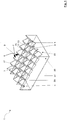
- FIG. 1 shows a common geometry of a retroreflector 1 as in the DE 102 16 579 A1 described.
- the retroreflector 1 is formed by a regular arrangement of individual triple 3.
- Each triple 3 has three optically active interfaces at which a transition from an optically denser medium, ie a material with a higher refractive index to an optically thinner medium, ie a material with a lower refractive index or a reverse transition can take place.
- These interfaces can also be referred to as side surfaces 5, 7, 9.
- light enters the optically denser medium at a light entry surface opposite the reflector side and strikes the triple 3 at an angle under which total reflection takes place.
- the light beam is reflected once at each of the side surfaces 5, 7, 9.
- a component of the propagation vector changes sign.
- the light beam 29 leaves the retroreflector 1 again parallel to the direction of the incident beam 27.
- the surfaces 5, 7 and 9 form a right angle with each other.
- FIG. 1 Intersect the surfaces 5 and 7 in the edge 11 with the edge length a, the surfaces 5 and 9 in the edge 13 with the edge length b and the surfaces 7 and 9 in the edge 15 with the edge length c.
- the point of intersection of all three surfaces 5, 7, 9 forms the apex 17.
- an axis of symmetry 19 can be set, which encloses the same angle to all side surfaces 5, 7, 9.
- the triple 3 are slightly inclined. So there is a tilt 23 before.
- the axis 19 of the triple 3 is not parallel to a normal vector of a plane 25 in which the triples are arranged.
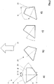
- FIG. 2 shows a plan view of a single triple 3 of a retroreflector 1 as in FIG. 1 ,
- FIG. 2a is a triplet shown without tilting.
- the symmetry axis 19 is collinear with a normal vector of a plane 25 of the triple according to FIG FIG. 1 ,
- a possible rotation 21 of the triple 3 about the axis 19 is indicated by an arrow with the reference number of the angle of rotation ⁇ .
- the angle ⁇ of the first side surface 5 to the axis of symmetry 19 of the triple 3 is 35.26 °.
- the angle ⁇ of the second side surface 5 to the symmetry axis 19 of the triple 3 corresponds to the angle of the diagonal of a cube and is 54.74 °.
- the sum of ⁇ and ⁇ and thus the intersection angle of the first side surface 5 with the second side surface 7 is exactly 90 °.
- the third side surface 9 lies here in the plane of the drawing and, together with the two other side surfaces 5, 7, likewise forms a
- FIGS. 2b ) to d) show the triple with three different tilt angles ⁇ .
- the tilt angle ⁇ is smaller than 54.74 ° in Figure 2c the tilt angle ⁇ is exactly 54.74 °. That is, the first side surface 5 is coplanar with the plane 25 of the triple.
- the tilt angle ⁇ is greater than 54.74 °. It is understood that the triples can also be twisted twisted 21 and tilted 23 can be.
- the in the FIGS. 2b) and 2c ) shown triple 3 can be in a Entformungscardi 31 without undercut from an imaginary tool removed from the mold.
- the in Figure 2d ) shown triple 3 has an undercut 33.
- the designated 33 area is opposite to the Entformungscardi 31 of demolding.
- the in FIG. 2 d) shown triple can therefore only be removed from the mold, if it consists of an elastic material, such as silicone, according to the invention.
- FIG. 3 shows by way of example the retroreflection on a curved surface 135.
- the side surfaces 105, 107 of the triple 103 are shown.
- Incident light 127 first strikes the side surface 105, is reflected there and then strikes the side surface 107 and is reflected there.
- the reflection on the side surface 109 is not shown.
- the order of impingement of the incident light beam 127 on the side surfaces 105, 107, 109 may be arbitrarily permuted.
- the area of the light entry surface that illuminates exactly one triple 103 is indicated as an aperture 143 with an arrow. Because the surface 135 is curved, the aperture 143 is also curved.
- the radius of the sphere or generally the local radius of curvature of the curved surface 135 by at least a factor of 10, preferably at least by a factor of 50, particularly preferred.
- the axis 119 of the triple 103 points in the radial direction R, at least by a factor of 100 times the size of the largest edge length of the triple.
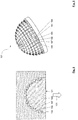
- FIG. 4 shows the view of the retroreflector 101 in the form of a hemisphere 141 shown.
- the curved surface 135 thus has a spherical shape.
- the curved surface 135 can thus be defined by a spherical coordinate system with a radial vector R (see FIG. 3 ), a polar angle ⁇ and an azimuth angle ⁇ . So there are two curvature directions.
- all side surfaces 105, 107, 109 of a triple 103 as well as the edges 111, 113, 115 are visible.
- the edges 111, 113, 115 intersect in the apex 117.
- the triplets 103 are in proportion to the hemisphere radius of the recognizability because of clearly too big drawn. Placing two such components together on the circumference results in a solid sphere approximately at the solid angle 4 ⁇ .
- Such spheres of suitable diameter can be used, for example, as operation markers.
- FIGS. 5 and 6 show a mold with a mold insert 151 for producing a retroreflector 101 FIG. 4 ,
- the first molding surface 155 of a triple 153 of the mold insert 151 corresponds to the first side surface 105 of a triple 103 of the retroreflector 101.
- the reference numerals of the mold insert 151 differ from the reference numerals of the retroreflector 101 by 50. The same applies to the surfaces 157 and 159, the edges 161, 163, 165, the triple center 167 and the symmetry axis 169 of the triple 153.
- FIG. 5 the shape is shown in a closed state.
- a Entformungscardi 131 is perpendicular to the plane base of the mold.
- Undercuts 133 are clearly visible in the lower area near the base plate of the molding tool. For reasons of clarity, a representation of a heater of the shape required for curing the silicone was dispensed with.
- FIG. 6 shows the mold insert in the open state.
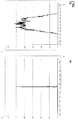
- FIG. 7 an intensity distribution I is plotted in arbitrary units over an observation angle ⁇ .
- FIG. 7 a) shows the angular distribution of the retroreflected light for an ideal triple at a flat aperture area. The half width is zero except for presentation-related resolution.
- FIG. 7b) shows the angular distribution for the same ideal triple but with curved aperture surface 143 (see FIG. 3 ). The radius of curvature is chosen here so that there is approximately a half-width of the angular distribution of 0.5 °.
- FIG. 8 2 shows symbolically illustrated in two dimensions the adaptation of an elastic retroreflector 201 molded in a plane plane to a curved surface 235 of an object 237.
- FIG. 8a shows the Retroreflector 201 before being applied to the article 237.
- FIG. 8b shows the retroreflector 201 and the article 237 after application of the retroreflector.
- the sizes of the triple 203 are greatly exaggerated.
- the deformations in particular of the triple 203 in FIG. 8b ) greatly exaggerated.
- a local radius of curvature of the curved surface 235 is at least a factor of 50, better still at least a factor of 100, greater than the edge lengths or key widths of the triple 203.
- FIG. 8 Because of the symbolic two-dimensional representation only two side surfaces 205, 207, or two edges 211, 213 of a triple 203 are shown. The edges intersect in the apex 217.
- the axis of symmetry 219 which passes through the apex 217 and encloses the same angle with the side surfaces 205, 207, lies in FIG. 8a ), that is, before attaching the elastic retroreflector 201 to the object 237, parallel to the normal vector of a plane 225.
- the plane 225 corresponds to a flat wall in an injection mold, not shown.
- the symmetry axis 219 follows in the example of FIG. 8b ) of the curved surface 235 of the object 237.
- the in FIG. 8b ) exaggerated elastic deformations of the retroreflector 201 may on the one hand have a negative effect on the reflection behavior of the reflector, but on the other hand can also be used to achieve, for example, a desired angular distribution.
- FIG. 9 shows a schematic 2d representation of a retroreflector 301 according to the invention, which is intended for use in a Sensoror worn in which emitted from a light source, not shown, ultraviolet light, ie an incident beam 327, for example with a wavelength of 280 nm, to a light receiver, not shown is directed as retroflected beam 329.
- the retroreflector 301 has an arrangement of triples 303, each with three side faces nearly perpendicular to one another, of which a first side face 305 and a second side face 307 are illustrated.
- the retroreflector 301 in FIG. 9 is not curved so flat designed. Nevertheless, the elastic property of the silicone can be used to press or over an undercut 333 of the retroreflector 301, or preferably a groove, into a holder 339, preferably a rigid holder 339.
- the retroreflector 301 can be attached to the holder. Thanks to the elastic material of the silicone can thus be created a closed rear surface. Welding can thus be dispensed with.
Landscapes
- Engineering & Computer Science (AREA)
- Physics & Mathematics (AREA)
- General Physics & Mathematics (AREA)
- Health & Medical Sciences (AREA)
- Manufacturing & Machinery (AREA)
- Ophthalmology & Optometry (AREA)
- Mechanical Engineering (AREA)
- Spectroscopy & Molecular Physics (AREA)
- Optics & Photonics (AREA)
- General Engineering & Computer Science (AREA)
- Moulds For Moulding Plastics Or The Like (AREA)
- Optical Elements Other Than Lenses (AREA)
Applications Claiming Priority (1)
| Application Number | Priority Date | Filing Date | Title |
|---|---|---|---|
| DE102018101291.8A DE102018101291B4 (de) | 2018-01-22 | 2018-01-22 | Verwendung und Verfahren zur Herstellung eines elastischen Retroreflektors |
Publications (3)
| Publication Number | Publication Date |
|---|---|
| EP3514582A2 true EP3514582A2 (fr) | 2019-07-24 |
| EP3514582A3 EP3514582A3 (fr) | 2019-09-25 |
| EP3514582B1 EP3514582B1 (fr) | 2023-01-18 |
Family
ID=64606842
Family Applications (1)
| Application Number | Title | Priority Date | Filing Date |
|---|---|---|---|
| EP18210406.7A Active EP3514582B1 (fr) | 2018-01-22 | 2018-12-05 | Rétroréflecteur élastique |
Country Status (4)
| Country | Link |
|---|---|
| US (2) | US11215740B2 (fr) |
| EP (1) | EP3514582B1 (fr) |
| DE (1) | DE102018101291B4 (fr) |
| DK (1) | DK3514582T3 (fr) |
Families Citing this family (4)
| Publication number | Priority date | Publication date | Assignee | Title |
|---|---|---|---|---|
| CA3137356A1 (fr) | 2019-04-26 | 2020-10-29 | Battelle Memorial Institute | Ouverture segmentee differentielle conforme/omnidirectionnelle |
| DE102019128755A1 (de) * | 2019-10-24 | 2021-04-29 | Imos Gubela Gmbh | Sensoreinrichtung |
| WO2021108930A1 (fr) * | 2019-12-06 | 2021-06-10 | Camso Inc. | Systèmes et procédés de surveillance d'ensembles roues |
| DE102020004967B4 (de) * | 2020-08-14 | 2024-08-01 | Hans-Erich Gubela | Retroreflektierendes Element mit einem Sicherheitselement |
Family Cites Families (25)
| Publication number | Priority date | Publication date | Assignee | Title |
|---|---|---|---|---|
| US3716445A (en) | 1970-06-24 | 1973-02-13 | J Lemelson | Reflex reflective sheeting |
| JPS5320837B1 (fr) | 1971-07-07 | 1978-06-29 | ||
| US3744117A (en) | 1971-09-30 | 1973-07-10 | Amerace Esna Corp | Method for making a curved cube-corner reflector |
| US3873184A (en) * | 1973-02-16 | 1975-03-25 | Amerace Esna Corp | Reflector with interspersed angled reflex elements |
| US5189553A (en) | 1992-06-08 | 1993-02-23 | Minnesota Mining And Manufacturing Company | Optimized construction of retroreflective articles for curved applications |
| DE4410994C2 (de) | 1992-10-30 | 1996-01-25 | Gubela Sen Hans Erich | Körper oder Bauteil eines strangförmigen Tripelreflektors und Werkzeugelement zur Abformung von Tripelreflektoren |
| US5376431A (en) * | 1993-05-12 | 1994-12-27 | Reflexite Corporation | Retroreflective microprism sheeting with silver/copper reflecting coating and method of making same |
| US5706132A (en) | 1996-01-19 | 1998-01-06 | Minnesota Mining And Manufacturing Company | Dual orientation retroreflective sheeting |
| DE10216579A1 (de) | 2002-04-14 | 2003-10-23 | Sen Hans-Erich Gubela | Weitwinkelsensorsystem mit Tripelreflektor und Herstellung der Werkzeuge |
| DE20207645U1 (de) | 2002-05-14 | 2002-08-29 | IMOS Gubela GmbH, 77871 Renchen | Kabelretroflektor mit einer Vielzahl von Tripeln |
| EP1623253A1 (fr) | 2003-03-06 | 2006-02-08 | 3M Innovative Properties Company | Lamine comprenant des elements en coin de cube et revetement retroreflechissant |
| WO2005114268A2 (fr) * | 2004-05-12 | 2005-12-01 | Reflexite Corporation | Structures retroreflechissantes |
| WO2006071863A1 (fr) * | 2004-12-28 | 2006-07-06 | 3M Innovative Properties Company | Article retroreflechissant prismatique a prismes contenant du fluor ou du silicium |
| DE102005009066A1 (de) | 2005-02-28 | 2006-09-07 | Osram Opto Semiconductors Gmbh | Verfahren zur Herstellung eines optischen und eines strahlungsemittierenden Bauelementes und optisches sowie strahlungsemittierendes Bauelement |
| JP4890800B2 (ja) * | 2005-06-29 | 2012-03-07 | スリーエム イノベイティブ プロパティズ カンパニー | 透明波長選択性再帰反射体 |
| US20100284080A1 (en) * | 2007-09-24 | 2010-11-11 | Reflexite Corporation | Retroreflective structure with fabric face |
| WO2010021133A1 (fr) * | 2008-08-20 | 2010-02-25 | 日本カーバイド工業株式会社 | Dispositif de fabrication de feuille optique et procédé de fabrication de feuille optique |
| DE102012022418B4 (de) | 2012-11-16 | 2019-08-22 | Hans-Erich Gubela sen. | Retroreflektor, optisches System, ortsfeste Anordnung eines Retroreflektors und Abformwerkzeug |
| EP2948803A1 (fr) | 2013-01-28 | 2015-12-02 | Aura Optical Systems, LP | Film rétroréfléchissant microprimastique métallisé présentant une meilleure angularité d'observation |
| FR3019314B1 (fr) | 2014-03-28 | 2017-08-11 | Gaggione Sas | Collimateur de lumiere |
| US9651206B2 (en) * | 2014-03-30 | 2017-05-16 | Khatod Optoelectronics Srl | Optic for a LED chip and related LED lighting device |
| DE202014102938U1 (de) | 2014-06-27 | 2014-08-05 | Walter Felix Sallaberger | Konturmarkierung für Fahrzeuge |
| DE102014212918A1 (de) * | 2014-07-03 | 2016-01-21 | Volkswagen Aktiengesellschaft | Kraftfahrzeug-Beleuchtungseinrichtung |
| DE102014223785A1 (de) | 2014-11-21 | 2016-05-25 | Wacker Chemie Ag | Härtbare hochtransparente Siliconzusammensetzung mit verbesserter Mechanik für optische Bauteile |
| DE112017002091A5 (de) | 2016-04-22 | 2019-01-10 | Technische Hochschule Nürnberg Georg Simon Ohm | An die Krümmung einer Grundfläche angepasste Retroreflektoranordnung und Verfahren zu seiner Berechnung |
-
2018
- 2018-01-22 DE DE102018101291.8A patent/DE102018101291B4/de active Active
- 2018-12-05 EP EP18210406.7A patent/EP3514582B1/fr active Active
- 2018-12-05 DK DK18210406.7T patent/DK3514582T3/da active
-
2019
- 2019-01-17 US US16/250,357 patent/US11215740B2/en active Active
-
2021
- 2021-11-12 US US17/525,546 patent/US12138873B2/en active Active
Also Published As
| Publication number | Publication date |
|---|---|
| DE102018101291B4 (de) | 2020-10-29 |
| EP3514582A3 (fr) | 2019-09-25 |
| US20220066074A1 (en) | 2022-03-03 |
| EP3514582B1 (fr) | 2023-01-18 |
| DE102018101291A1 (de) | 2019-07-25 |
| US11215740B2 (en) | 2022-01-04 |
| US20190227205A1 (en) | 2019-07-25 |
| US12138873B2 (en) | 2024-11-12 |
| DK3514582T3 (da) | 2023-04-03 |
Similar Documents
| Publication | Publication Date | Title |
|---|---|---|
| EP2212724B9 (fr) | Composant optique et dispositif d'éclairage | |
| EP1387982B1 (fr) | Element optique a reflexion totale | |
| EP3514582B1 (fr) | Rétroréflecteur élastique | |
| EP2691691B1 (fr) | Élément optique et dispositif émetteur d'un rayonnement doté d'un tel élément optique | |
| DE69508511T2 (de) | Lichtleiter-Beleuchtungssystem zur Herstellung eines dünnen Beleuchtungselements | |
| DE102004026530B3 (de) | Optikkörper | |
| DE112014003601T5 (de) | Spritzgegossene dicke Linse | |
| EP3523573B1 (fr) | Dispositif de déviation lumineuse, dispositif d'éclairage et utilisation | |
| EP3440403B1 (fr) | Conducteur lumineux avec structures de deviation de lumiere | |
| EP2158428B1 (fr) | Dispositif d'éclairage | |
| EP3655289B1 (fr) | Composant pour véhicule | |
| EP3805635A1 (fr) | Dispositif d'éclairage pourvu de lentille en imprimé silicone | |
| DE20107425U1 (de) | Entblendung von Leuchtmitteln | |
| EP3523572B1 (fr) | Dispositif de déflexion de la lumière, procédé de réalisation d'un dispositif de déflexion de la lumière et dispositif d'éclairage | |
| WO2017055516A1 (fr) | Panneau routier rétroréfléchissant, matériau en bande rétroréfléchissant et procédé de fabrication associé | |
| EP3513959B1 (fr) | Élément rétroréflecteur destiné à l'utilisation dans le transport routier | |
| EP3782208A1 (fr) | Module del comprenant une lentille en silicone appliquée par impression 3d | |
| EP3543600A2 (fr) | Tige de mélange permettant de mélanger un faisceau de rayons lumineux ainsi que dispositif d'éclairage doté d'une telle tige de mélange | |
| DE102011084270A1 (de) | Lichtleiter | |
| DE102018128124B4 (de) | Optik | |
| EP3313652B1 (fr) | Procédé de fabrication d'un reseau de lentilles, reseau de lentilles et utilisation d'un reseau de lentilles | |
| DE102019125640A1 (de) | Optisches Element | |
| EP3332433B1 (fr) | Procédé de fabrication de composants optoélectroniques actifs | |
| DE102016200380A1 (de) | Verfahren zur Herstellung einer Streuoptik sowie Streuoptik und Leuchte mit Streuoptik | |
| DE102014013548A1 (de) | LED-Leuchte mit einer Totalreflexions-Optik und verschachtelten Lichtumlenkflächen zur Herstellung von beliebigen Lichtaustrittsflächen |
Legal Events
| Date | Code | Title | Description |
|---|---|---|---|
| PUAI | Public reference made under article 153(3) epc to a published international application that has entered the european phase |
Free format text: ORIGINAL CODE: 0009012 |
|
| STAA | Information on the status of an ep patent application or granted ep patent |
Free format text: STATUS: THE APPLICATION HAS BEEN PUBLISHED |
|
| AK | Designated contracting states |
Kind code of ref document: A2 Designated state(s): AL AT BE BG CH CY CZ DE DK EE ES FI FR GB GR HR HU IE IS IT LI LT LU LV MC MK MT NL NO PL PT RO RS SE SI SK SM TR |
|
| AX | Request for extension of the european patent |
Extension state: BA ME |
|
| PUAL | Search report despatched |
Free format text: ORIGINAL CODE: 0009013 |
|
| AK | Designated contracting states |
Kind code of ref document: A3 Designated state(s): AL AT BE BG CH CY CZ DE DK EE ES FI FR GB GR HR HU IE IS IT LI LT LU LV MC MK MT NL NO PL PT RO RS SE SI SK SM TR |
|
| AX | Request for extension of the european patent |
Extension state: BA ME |
|
| RIC1 | Information provided on ipc code assigned before grant |
Ipc: B29D 11/00 20060101ALI20190822BHEP Ipc: G02B 5/124 20060101AFI20190822BHEP Ipc: G01J 1/04 20060101ALI20190822BHEP Ipc: F21S 41/33 20180101ALI20190822BHEP Ipc: G01J 1/42 20060101ALI20190822BHEP |
|
| STAA | Information on the status of an ep patent application or granted ep patent |
Free format text: STATUS: REQUEST FOR EXAMINATION WAS MADE |
|
| 17P | Request for examination filed |
Effective date: 20200320 |
|
| RBV | Designated contracting states (corrected) |
Designated state(s): AL AT BE BG CH CY CZ DE DK EE ES FI FR GB GR HR HU IE IS IT LI LT LU LV MC MK MT NL NO PL PT RO RS SE SI SK SM TR |
|
| REG | Reference to a national code |
Ref country code: DE Ref legal event code: R079 Ref document number: 502018011455 Country of ref document: DE Free format text: PREVIOUS MAIN CLASS: G02B0005124000 Ipc: B29C0045370000 |
|
| GRAP | Despatch of communication of intention to grant a patent |
Free format text: ORIGINAL CODE: EPIDOSNIGR1 |
|
| STAA | Information on the status of an ep patent application or granted ep patent |
Free format text: STATUS: GRANT OF PATENT IS INTENDED |
|
| RIC1 | Information provided on ipc code assigned before grant |
Ipc: B29D 11/00 20060101ALI20220622BHEP Ipc: G02B 5/124 20060101ALI20220622BHEP Ipc: B29C 45/37 20060101AFI20220622BHEP |
|
| GRAJ | Information related to disapproval of communication of intention to grant by the applicant or resumption of examination proceedings by the epo deleted |
Free format text: ORIGINAL CODE: EPIDOSDIGR1 |
|
| STAA | Information on the status of an ep patent application or granted ep patent |
Free format text: STATUS: REQUEST FOR EXAMINATION WAS MADE |
|
| INTG | Intention to grant announced |
Effective date: 20220721 |
|
| GRAJ | Information related to disapproval of communication of intention to grant by the applicant or resumption of examination proceedings by the epo deleted |
Free format text: ORIGINAL CODE: EPIDOSDIGR1 |
|
| GRAP | Despatch of communication of intention to grant a patent |
Free format text: ORIGINAL CODE: EPIDOSNIGR1 |
|
| INTC | Intention to grant announced (deleted) | ||
| INTG | Intention to grant announced |
Effective date: 20220909 |
|
| INTC | Intention to grant announced (deleted) | ||
| GRAS | Grant fee paid |
Free format text: ORIGINAL CODE: EPIDOSNIGR3 |
|
| STAA | Information on the status of an ep patent application or granted ep patent |
Free format text: STATUS: GRANT OF PATENT IS INTENDED |
|
| GRAP | Despatch of communication of intention to grant a patent |
Free format text: ORIGINAL CODE: EPIDOSNIGR1 |
|
| INTG | Intention to grant announced |
Effective date: 20221104 |
|
| GRAA | (expected) grant |
Free format text: ORIGINAL CODE: 0009210 |
|
| STAA | Information on the status of an ep patent application or granted ep patent |
Free format text: STATUS: THE PATENT HAS BEEN GRANTED |
|
| AK | Designated contracting states |
Kind code of ref document: B1 Designated state(s): AL AT BE BG CH CY CZ DE DK EE ES FI FR GB GR HR HU IE IS IT LI LT LU LV MC MK MT NL NO PL PT RO RS SE SI SK SM TR |
|
| REG | Reference to a national code |
Ref country code: GB Ref legal event code: FG4D Free format text: NOT ENGLISH |
|
| REG | Reference to a national code |
Ref country code: DE Ref legal event code: R096 Ref document number: 502018011455 Country of ref document: DE |
|
| REG | Reference to a national code |
Ref country code: CH Ref legal event code: EP |
|
| REG | Reference to a national code |
Ref country code: AT Ref legal event code: REF Ref document number: 1544446 Country of ref document: AT Kind code of ref document: T Effective date: 20230215 Ref country code: IE Ref legal event code: FG4D Free format text: LANGUAGE OF EP DOCUMENT: GERMAN |
|
| REG | Reference to a national code |
Ref country code: DK Ref legal event code: T3 Effective date: 20230329 |
|
| REG | Reference to a national code |
Ref country code: LT Ref legal event code: MG9D |
|
| REG | Reference to a national code |
Ref country code: NL Ref legal event code: MP Effective date: 20230118 |
|
| P01 | Opt-out of the competence of the unified patent court (upc) registered |
Effective date: 20230522 |
|
| PG25 | Lapsed in a contracting state [announced via postgrant information from national office to epo] |
Ref country code: NL Free format text: LAPSE BECAUSE OF FAILURE TO SUBMIT A TRANSLATION OF THE DESCRIPTION OR TO PAY THE FEE WITHIN THE PRESCRIBED TIME-LIMIT Effective date: 20230118 |
|
| PG25 | Lapsed in a contracting state [announced via postgrant information from national office to epo] |
Ref country code: RS Free format text: LAPSE BECAUSE OF FAILURE TO SUBMIT A TRANSLATION OF THE DESCRIPTION OR TO PAY THE FEE WITHIN THE PRESCRIBED TIME-LIMIT Effective date: 20230118 Ref country code: PT Free format text: LAPSE BECAUSE OF FAILURE TO SUBMIT A TRANSLATION OF THE DESCRIPTION OR TO PAY THE FEE WITHIN THE PRESCRIBED TIME-LIMIT Effective date: 20230518 Ref country code: NO Free format text: LAPSE BECAUSE OF FAILURE TO SUBMIT A TRANSLATION OF THE DESCRIPTION OR TO PAY THE FEE WITHIN THE PRESCRIBED TIME-LIMIT Effective date: 20230418 Ref country code: LV Free format text: LAPSE BECAUSE OF FAILURE TO SUBMIT A TRANSLATION OF THE DESCRIPTION OR TO PAY THE FEE WITHIN THE PRESCRIBED TIME-LIMIT Effective date: 20230118 Ref country code: LT Free format text: LAPSE BECAUSE OF FAILURE TO SUBMIT A TRANSLATION OF THE DESCRIPTION OR TO PAY THE FEE WITHIN THE PRESCRIBED TIME-LIMIT Effective date: 20230118 Ref country code: HR Free format text: LAPSE BECAUSE OF FAILURE TO SUBMIT A TRANSLATION OF THE DESCRIPTION OR TO PAY THE FEE WITHIN THE PRESCRIBED TIME-LIMIT Effective date: 20230118 Ref country code: ES Free format text: LAPSE BECAUSE OF FAILURE TO SUBMIT A TRANSLATION OF THE DESCRIPTION OR TO PAY THE FEE WITHIN THE PRESCRIBED TIME-LIMIT Effective date: 20230118 |
|
| PG25 | Lapsed in a contracting state [announced via postgrant information from national office to epo] |
Ref country code: SE Free format text: LAPSE BECAUSE OF FAILURE TO SUBMIT A TRANSLATION OF THE DESCRIPTION OR TO PAY THE FEE WITHIN THE PRESCRIBED TIME-LIMIT Effective date: 20230118 Ref country code: PL Free format text: LAPSE BECAUSE OF FAILURE TO SUBMIT A TRANSLATION OF THE DESCRIPTION OR TO PAY THE FEE WITHIN THE PRESCRIBED TIME-LIMIT Effective date: 20230118 Ref country code: IS Free format text: LAPSE BECAUSE OF FAILURE TO SUBMIT A TRANSLATION OF THE DESCRIPTION OR TO PAY THE FEE WITHIN THE PRESCRIBED TIME-LIMIT Effective date: 20230518 Ref country code: GR Free format text: LAPSE BECAUSE OF FAILURE TO SUBMIT A TRANSLATION OF THE DESCRIPTION OR TO PAY THE FEE WITHIN THE PRESCRIBED TIME-LIMIT Effective date: 20230419 Ref country code: FI Free format text: LAPSE BECAUSE OF FAILURE TO SUBMIT A TRANSLATION OF THE DESCRIPTION OR TO PAY THE FEE WITHIN THE PRESCRIBED TIME-LIMIT Effective date: 20230118 |
|
| REG | Reference to a national code |
Ref country code: DE Ref legal event code: R097 Ref document number: 502018011455 Country of ref document: DE |
|
| PG25 | Lapsed in a contracting state [announced via postgrant information from national office to epo] |
Ref country code: SM Free format text: LAPSE BECAUSE OF FAILURE TO SUBMIT A TRANSLATION OF THE DESCRIPTION OR TO PAY THE FEE WITHIN THE PRESCRIBED TIME-LIMIT Effective date: 20230118 Ref country code: RO Free format text: LAPSE BECAUSE OF FAILURE TO SUBMIT A TRANSLATION OF THE DESCRIPTION OR TO PAY THE FEE WITHIN THE PRESCRIBED TIME-LIMIT Effective date: 20230118 Ref country code: EE Free format text: LAPSE BECAUSE OF FAILURE TO SUBMIT A TRANSLATION OF THE DESCRIPTION OR TO PAY THE FEE WITHIN THE PRESCRIBED TIME-LIMIT Effective date: 20230118 Ref country code: CZ Free format text: LAPSE BECAUSE OF FAILURE TO SUBMIT A TRANSLATION OF THE DESCRIPTION OR TO PAY THE FEE WITHIN THE PRESCRIBED TIME-LIMIT Effective date: 20230118 |
|
| PLBE | No opposition filed within time limit |
Free format text: ORIGINAL CODE: 0009261 |
|
| STAA | Information on the status of an ep patent application or granted ep patent |
Free format text: STATUS: NO OPPOSITION FILED WITHIN TIME LIMIT |
|
| PG25 | Lapsed in a contracting state [announced via postgrant information from national office to epo] |
Ref country code: SK Free format text: LAPSE BECAUSE OF FAILURE TO SUBMIT A TRANSLATION OF THE DESCRIPTION OR TO PAY THE FEE WITHIN THE PRESCRIBED TIME-LIMIT Effective date: 20230118 |
|
| 26N | No opposition filed |
Effective date: 20231019 |
|
| PG25 | Lapsed in a contracting state [announced via postgrant information from national office to epo] |
Ref country code: SI Free format text: LAPSE BECAUSE OF FAILURE TO SUBMIT A TRANSLATION OF THE DESCRIPTION OR TO PAY THE FEE WITHIN THE PRESCRIBED TIME-LIMIT Effective date: 20230118 |
|
| REG | Reference to a national code |
Ref country code: DK Ref legal event code: EBP Effective date: 20231231 |
|
| REG | Reference to a national code |
Ref country code: CH Ref legal event code: PL |
|
| PG25 | Lapsed in a contracting state [announced via postgrant information from national office to epo] |
Ref country code: LU Free format text: LAPSE BECAUSE OF NON-PAYMENT OF DUE FEES Effective date: 20231205 |
|
| PG25 | Lapsed in a contracting state [announced via postgrant information from national office to epo] |
Ref country code: MC Free format text: LAPSE BECAUSE OF FAILURE TO SUBMIT A TRANSLATION OF THE DESCRIPTION OR TO PAY THE FEE WITHIN THE PRESCRIBED TIME-LIMIT Effective date: 20230118 |
|
| REG | Reference to a national code |
Ref country code: BE Ref legal event code: MM Effective date: 20231231 |
|
| PG25 | Lapsed in a contracting state [announced via postgrant information from national office to epo] |
Ref country code: MC Free format text: LAPSE BECAUSE OF FAILURE TO SUBMIT A TRANSLATION OF THE DESCRIPTION OR TO PAY THE FEE WITHIN THE PRESCRIBED TIME-LIMIT Effective date: 20230118 Ref country code: LU Free format text: LAPSE BECAUSE OF NON-PAYMENT OF DUE FEES Effective date: 20231205 |
|
| REG | Reference to a national code |
Ref country code: IE Ref legal event code: MM4A |
|
| PG25 | Lapsed in a contracting state [announced via postgrant information from national office to epo] |
Ref country code: IE Free format text: LAPSE BECAUSE OF NON-PAYMENT OF DUE FEES Effective date: 20231205 |
|
| PG25 | Lapsed in a contracting state [announced via postgrant information from national office to epo] |
Ref country code: BE Free format text: LAPSE BECAUSE OF NON-PAYMENT OF DUE FEES Effective date: 20231231 |
|
| PG25 | Lapsed in a contracting state [announced via postgrant information from national office to epo] |
Ref country code: CH Free format text: LAPSE BECAUSE OF NON-PAYMENT OF DUE FEES Effective date: 20231231 |
|
| PG25 | Lapsed in a contracting state [announced via postgrant information from national office to epo] |
Ref country code: IE Free format text: LAPSE BECAUSE OF NON-PAYMENT OF DUE FEES Effective date: 20231205 Ref country code: CH Free format text: LAPSE BECAUSE OF NON-PAYMENT OF DUE FEES Effective date: 20231231 Ref country code: BE Free format text: LAPSE BECAUSE OF NON-PAYMENT OF DUE FEES Effective date: 20231231 |
|
| PG25 | Lapsed in a contracting state [announced via postgrant information from national office to epo] |
Ref country code: BG Free format text: LAPSE BECAUSE OF FAILURE TO SUBMIT A TRANSLATION OF THE DESCRIPTION OR TO PAY THE FEE WITHIN THE PRESCRIBED TIME-LIMIT Effective date: 20230118 |
|
| PG25 | Lapsed in a contracting state [announced via postgrant information from national office to epo] |
Ref country code: BG Free format text: LAPSE BECAUSE OF FAILURE TO SUBMIT A TRANSLATION OF THE DESCRIPTION OR TO PAY THE FEE WITHIN THE PRESCRIBED TIME-LIMIT Effective date: 20230118 |
|
| PG25 | Lapsed in a contracting state [announced via postgrant information from national office to epo] |
Ref country code: DK Free format text: LAPSE BECAUSE OF NON-PAYMENT OF DUE FEES Effective date: 20231231 |
|
| PG25 | Lapsed in a contracting state [announced via postgrant information from national office to epo] |
Ref country code: DK Free format text: LAPSE BECAUSE OF NON-PAYMENT OF DUE FEES Effective date: 20231231 |
|
| REG | Reference to a national code |
Ref country code: AT Ref legal event code: MM01 Ref document number: 1544446 Country of ref document: AT Kind code of ref document: T Effective date: 20231205 |
|
| PG25 | Lapsed in a contracting state [announced via postgrant information from national office to epo] |
Ref country code: AT Free format text: LAPSE BECAUSE OF NON-PAYMENT OF DUE FEES Effective date: 20231205 |
|
| PG25 | Lapsed in a contracting state [announced via postgrant information from national office to epo] |
Ref country code: CY Free format text: LAPSE BECAUSE OF FAILURE TO SUBMIT A TRANSLATION OF THE DESCRIPTION OR TO PAY THE FEE WITHIN THE PRESCRIBED TIME-LIMIT; INVALID AB INITIO Effective date: 20181205 |
|
| PG25 | Lapsed in a contracting state [announced via postgrant information from national office to epo] |
Ref country code: HU Free format text: LAPSE BECAUSE OF FAILURE TO SUBMIT A TRANSLATION OF THE DESCRIPTION OR TO PAY THE FEE WITHIN THE PRESCRIBED TIME-LIMIT; INVALID AB INITIO Effective date: 20181205 |
|
| PG25 | Lapsed in a contracting state [announced via postgrant information from national office to epo] |
Ref country code: TR Free format text: LAPSE BECAUSE OF FAILURE TO SUBMIT A TRANSLATION OF THE DESCRIPTION OR TO PAY THE FEE WITHIN THE PRESCRIBED TIME-LIMIT Effective date: 20230118 |
|
| PGFP | Annual fee paid to national office [announced via postgrant information from national office to epo] |
Ref country code: DE Payment date: 20251104 Year of fee payment: 8 |
|
| PGFP | Annual fee paid to national office [announced via postgrant information from national office to epo] |
Ref country code: GB Payment date: 20251219 Year of fee payment: 8 |
|
| PGFP | Annual fee paid to national office [announced via postgrant information from national office to epo] |
Ref country code: IT Payment date: 20251223 Year of fee payment: 8 |
|
| PGFP | Annual fee paid to national office [announced via postgrant information from national office to epo] |
Ref country code: FR Payment date: 20251229 Year of fee payment: 8 |