EP3516937B1 - Boitier de calculateur automobile, calculateur et vehicule correspondant - Google Patents
Boitier de calculateur automobile, calculateur et vehicule correspondant Download PDFInfo
- Publication number
- EP3516937B1 EP3516937B1 EP17780474.7A EP17780474A EP3516937B1 EP 3516937 B1 EP3516937 B1 EP 3516937B1 EP 17780474 A EP17780474 A EP 17780474A EP 3516937 B1 EP3516937 B1 EP 3516937B1
- Authority
- EP
- European Patent Office
- Prior art keywords
- compartment
- computer
- wall
- housing
- electronic
- Prior art date
- Legal status (The legal status is an assumption and is not a legal conclusion. Google has not performed a legal analysis and makes no representation as to the accuracy of the status listed.)
- Active
Links
Images
Classifications
-
- H—ELECTRICITY
- H05—ELECTRIC TECHNIQUES NOT OTHERWISE PROVIDED FOR
- H05K—PRINTED CIRCUITS; CASINGS OR CONSTRUCTIONAL DETAILS OF ELECTRIC APPARATUS; MANUFACTURE OF ASSEMBLAGES OF ELECTRICAL COMPONENTS
- H05K5/00—Casings, cabinets or drawers for electric apparatus
- H05K5/0026—Casings, cabinets or drawers for electric apparatus provided with connectors and printed circuit boards [PCB], e.g. automotive electronic control units
- H05K5/0065—Casings, cabinets or drawers for electric apparatus provided with connectors and printed circuit boards [PCB], e.g. automotive electronic control units wherein modules are associated together, e.g. electromechanical assemblies, modular structures
-
- H—ELECTRICITY
- H05—ELECTRIC TECHNIQUES NOT OTHERWISE PROVIDED FOR
- H05K—PRINTED CIRCUITS; CASINGS OR CONSTRUCTIONAL DETAILS OF ELECTRIC APPARATUS; MANUFACTURE OF ASSEMBLAGES OF ELECTRICAL COMPONENTS
- H05K5/00—Casings, cabinets or drawers for electric apparatus
- H05K5/0026—Casings, cabinets or drawers for electric apparatus provided with connectors and printed circuit boards [PCB], e.g. automotive electronic control units
- H05K5/0039—Casings, cabinets or drawers for electric apparatus provided with connectors and printed circuit boards [PCB], e.g. automotive electronic control units having a tubular housing wherein the PCB is inserted longitudinally
Definitions
- the invention relates to the field of computer boxes on board motor vehicles. It relates more particularly to an automobile computer case, automobile computers and a vehicle equipped with automobile computers.
- An electronic computer card is conventionally placed in a computer housing to protect it against possible damage linked in particular to shocks and vibrations inherent to the operation of a vehicle.
- Automotive computer housings comprising a compartment intended to receive an electronic computer card.
- the computer electronic card once placed in the housing, is connected to a cable, a portion of which is present outside the housing to electrically connect the computer to an electronic system, for example a driving assistance device or electronic comfort equipment.
- an electronic system for example a driving assistance device or electronic comfort equipment.
- US5057971 which protects the external connectors of a computer case from dust by means of a cover.
- the invention proposes a solution aimed at overcoming the aforementioned drawbacks.
- An objective of the invention is to reduce the bulk and mass induced in a vehicle by the presence of on-board automobile computers.
- the invention relates to an automobile computer housing intended to receive several electronic computer cards, characterized in that it comprises a first compartment arranged to receive several electronic computer cards mounted in parallel on rails in a removable manner, a second compartment arranged to receive connection cables and comprising openings passing through to the outside of the housing to allow the passage of the cables towards the outside of the housing, the first compartment and the second compartment having a first common wall, said first wall comprising at least one through opening arranged to receive at least one connector for electrically connecting an electronic computer card to a cable, the electronic computer card being arranged so that its side edges slide in the rails and that it is connected to connectors located opposite its rear edge.
- the first compartment makes it possible to bring together several electronic computer cards in the same housing, which makes it possible to reduce the number of computer housings necessary and therefore the bulk and mass induced in a vehicle by the presence of on-board automobile computers. Furthermore, the bringing together of the electronic cards obtained by placing them in a first compartment makes it possible to reduce the quantity of cables required, which contributes to a reduction in vehicle manufacturing costs in addition to a reduction in size and weight. . Grouping the cables in a second compartment and arranging the connectors on the same wall allows cabling to be optimized.
- the automobile computer case further comprises a third compartment arranged to receive electronic cards of protection components mounted in parallel on rails in a removable manner, the third compartment and the second compartment having a second common wall, said second wall comprising at least one through hole arranged to receive at least one connector for electrically connecting an electronic card of protection components to a cable.
- protection components we mean electrical relays or fuses. Electrical relays are commonly called contactors and carry out switching in a power circuit based on a command from a control circuit. The arrangement of the protection components close to the computer electronic cards makes it possible to further optimize the wiring.
- the second wall is arranged in the extension of the first wall.
- the first wall and the second wall are thus placed in the same plane, consequently the connectors connected to the computer electronic cards and to the protection component electronic cards are in the same plane which simplifies the wiring.
- the first compartment and the third compartment respectively comprise a first opening and a second opening towards the outside opposite the first wall and the second wall respectively.
- the first opening and the second opening allow, during a maintenance operation in particular, rapid access respectively to the computer electronic cards and the protection component electronic cards.
- the automobile computer housing further comprises at least one removable cover arranged to close the first opening and the second opening.
- the removable cover allows you to alternately obtain an open case, to allow a maintenance operation for example, and a closed case to effectively protect its contents from possible damage.
- the automobile computer box further comprises said at least one connector.
- the automobile computer box further comprises said connection cables.
- the invention also relates to an automobile computer characterized in that it comprises a housing according to the invention and said electronic computer cards.
- the invention also relates to a vehicle automobile characterized in that it comprises an automobile computer according to the invention.
- the motor vehicle further comprising a foot cellar on the passenger side, the automobile computer is placed in the foot cellar.
- the location of the automobile computer in the foot cellar allows the computer to be located close to the driving assistance devices and electronic comfort equipment conventionally integrated into the dashboard to limit the necessary wiring while freeing up space. located above the vehicle floor.
- the computer is intended to be embedded in a motor vehicle.
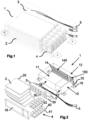
- the computer comprises a housing 1, several electronic computer boards 2, connectors 3, electronic boards of protection components 4 and cables 5.
- the housing 1 comprises a first compartment 11, a second compartment 12 and a third compartment 13.
- the first compartment 11 is separated from the second compartment 12 by a first wall 14.
- the third compartment 13 is separated from the second compartment 12 by a second wall 15 , placed in this example in the extension of the first wall 14.
- the first wall 14 has through holes 140 arranged to receive connectors 3 for electrically connecting an electronic computer card 2 to a cable 5.
- the second wall 15 has through holes 150 arranged to receive connectors 3 for electrically connecting an electronic card of protection components 4 to a cable 5.
- the first compartment 11 and the third compartment 13 respectively comprise a first opening 16 and a second opening 17 towards the outside of the housing facing the first wall 14 and the second wall 15.
- the housing further comprises a removable cover 18 arranged to close the first opening 16 and the second opening 17.
- the housing also includes fixing elements 19 arranged to allow the housing to be fixed in a motor vehicle.
- the fixing elements 19 comprise, for example, lugs projecting from the housing 1 and pierced with an orifice intended to receive a screw for screw/nut type fixing of the housing in the vehicle.
- the fixing elements 19 are glued or welded to the vehicle.
- the connectors 3 are placed in the through holes 140 or 150 of suitable shapes.
- the ends of a connector 3 extend beyond the through orifice 140 or 150 when the connector 3 is placed in the through orifice 140 or 150.
- the ends are for example pierced with an orifice intended to receive a screw for screw/nut type fixing of a connector 3 in the first wall 14 or the second wall 15.
- the connectors 3 are glued, welded or fitted into the first wall 14 or the second wall 15.
- the first compartment 11 comprises at least two side walls connecting the first wall 14 to the first opening 16.
- the side walls each have an internal face.
- the internal faces of the two side walls are parallel to each other.
- the internal faces are equipped with rails (not shown) arranged in rows extending parallel in a direction connecting the first wall 14 to the first opening 16.
- the rails are arranged in pairs, each of the two internal faces of the first compartment comprising a rail of the pair.
- the electronic computer cards 2 have at least four edges including a front edge intended to face the opening 16, a rear edge intended to face the wall 14 and two side edges parallel to each other, the two side edges being able to slide simultaneously respectively in the rails of a pair.
- a computer electronic card 2 When a computer electronic card 2 is arranged so that its side edges slide in rails, its rear edge is placed near the connectors 3 fixed to the first wall 16.
- the rear edge has protruding electrical connection plugs 20 intended to be connected to connectors 3 located opposite the rear edge.
- the rails and the connection of the plugs 20 in the connectors 3 make it possible to keep the computer electronic card 2 removably fixed in compartment 11.
- the arrangement of the electronic cards of protection components 4 in the third compartment 13 is identical to that of the electronic cards of computer 2 in the first compartment 11, mutatis mutandis.
- Each cable 5 connects two connectors together inside the second compartment or connects a connector to an electronic component outside the housing.
- the cables 5 connecting a connector to an electronic component external to the housing pass outside the housing through a through hole making a passage outwards into the second compartment.
- the box 1 is for example fixed to the floor of the vehicle in the passenger side footwell. It is protected by a footrest for the passenger.
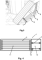
- the schematic sectional view of the computer 1 corresponds to a view along an axis perpendicular to the plane of the electronic cards 2 and the electronic cards of protection components 4.
- This view presents an example of positioning of the rails 10 (for reasons of readability of same as for the cards, not all the rails have been identified by arrows) within the first compartment 11 and the third compartment 13.
- the advantage of a third compartment accommodates electronic cards of mounted protection components parallel on rails 10 in a removable manner is to obtain a rationally organized housing to allow efficient and rapid maintenance when the protection components need to be changed.
- the components of protection are designed to fail before the components of the electronic computer cards and therefore need to be changed more frequently.
- the fact of grouping these protection components in a third dedicated compartment and organizing them by assembling these components on cards mounted in parallel on rails 10 in a removable manner allows easy and rapid access to the targeted protection component.
Landscapes
- Engineering & Computer Science (AREA)
- Microelectronics & Electronic Packaging (AREA)
- Casings For Electric Apparatus (AREA)
Description
- L'invention concerne le domaine des boîtiers de calculateurs embarqués à bord de véhicules automobiles. Elle concerne plus particulièrement un boîtier de calculateur automobile, des calculateurs automobile et un véhicule équipé des calculateurs automobile.
- Les véhicules actuels sont équipés de dispositifs d'aide à la conduite et d'équipements électroniques de confort nécessitant des capacités de calcul de plus en plus importantes ce qui entraîne une augmentation du nombre de cartes électroniques de calculateur embarquées dans les véhicules.
- Une carte électronique de calculateur est classiquement placée dans un boîtier de calculateur pour la protéger contre d'éventuelles détériorations liées notamment aux chocs et vibrations inhérents au fonctionnement d'un véhicule.
- Il est connu des boîtiers de calculateur automobile comportant un compartiment destiné à recevoir une carte électronique de calculateur. La carte électronique de calculateur, une fois placée dans le boîtier, est connectée à un câble dont une portion est présente à l'extérieur du boîtier pour connecter électriquement le calculateur à un système électronique, par exemple un dispositif d'aide à la conduite ou un équipement électronique de confort. On connaît aussi la demande de brevet
US5057971 qui protège de la poussière les connecteurs extérieurs d'un boîtier de calculateur au moyen d'un carter. - Les véhicules conventionnels comptent ainsi un boîtier de calculateur pour chaque carte électronique de calculateur, ce qui représente une masse et un volume embarqué conséquents. Ainsi, l'augmentation du nombre de cartes électroniques entraîne une augmentation de la masse embarquée et de l'encombrement dans le véhicule allant à l'encontre d'une économie de carburant et d'une réduction de l'impact environnemental.
- L'invention propose une solution visant à pallier les inconvénients précités. Un objectif de l'invention est de réduire l'encombrement et la masse induits dans un véhicule par la présence de calculateurs automobiles embarqués.
- L'invention concerne un boîtier de calculateur automobile destiné à recevoir plusieurs cartes électroniques de calculateur caractérisé en ce qu'il comporte un premier compartiment agencé pour recevoir plusieurs cartes électroniques de calculateur montées parallèlement sur des rails de manière amovible, un deuxième compartiment agencé pour recevoir des câbles de connexion et comprenant des orifices traversant vers l'extérieur du boîtier pour permettre le passage des câbles vers l'extérieur du boîtier, le premier compartiment et le deuxième compartiment ayant une première paroi commune, ladite première paroi comportant au moins un orifice traversant agencé pour recevoir au moins un connecteur pour connecter électriquement une carte électronique de calculateur à un câble, la carte électronique de calculateur étant agencée de sorte que ses bords latéraux coulissent dans les rails et qu'elle est branchée à des connecteurs situés en regard de son bord arrière.. Le premier compartiment permet de rassembler plusieurs cartes électroniques de calculateur dans un même boîtier ce qui permet de réduire le nombre de boîtiers de calculateur nécessaires et donc l'encombrement et la masse induits dans un véhicule par la présence de calculateurs automobiles embarqués. Par ailleurs, le rapprochement des cartes électroniques entre elles obtenu en les plaçant dans un premier compartiment permet de réduire la quantité de câbles nécessaires ce qui contribue à une réduction de coûts de fabrication du véhicule en plus d'une réduction d'encombrement et de masse. Le regroupement des câbles dans un deuxième compartiment et la disposition des connecteurs sur une même paroi permet d'optimiser le câblage.
- Selon un mode de réalisation particulier, le boîtier de calculateur automobile comporte en outre un troisième compartiment agencé pour recevoir des cartes électroniques de composants de protection montées parallèlement sur des rails de manière amovible, le troisième compartiment et le deuxième compartiment ayant une deuxième paroi commune, ladite deuxième paroi comportant au moins un orifice traversant agencé pour recevoir au moins un connecteur pour connecter électriquement une carte électroniques de composants de protection à un câble. On entend par composants de protection des relais électriques ou des fusibles. Les relais électriques sont communément appelés contacteurs et réalisent une commutation dans un circuit de puissance en fonction d'une commande issue d'un circuit de commande. La disposition des composants de protection à proximité des cartes électroniques de calculateur permet d'optimiser encore davantage le câblage.
- Selon un mode de réalisation particulier, la deuxième paroi est disposée dans le prolongement de la première paroi. La première paroi et la deuxième paroi sont ainsi placées dans un même plan, par conséquent les connecteurs connectés aux cartes électroniques de calculateur et aux cartes électronique de composants de protection sont dans un même plan ce qui simplifie le câblage.
- Selon un mode de réalisation particulier, le premier compartiment et le troisième compartiment comportent respectivement une première ouverture et une deuxième ouverture vers l'extérieur à l'opposé respectivement de la première paroi et de la deuxième paroi. La première ouverture et la deuxième ouverture permettent, pendant une opération de maintenance notamment, d'accéder rapidement respectivement aux cartes électroniques de calculateur et aux cartes électroniques de composants de protection.
- Selon un mode de réalisation particulier, le boîtier de calculateur automobile comporte en outre au moins un couvercle amovible agencé pour obturer la première ouverture et la deuxième ouverture. Le couvercle amovible permet d'obtenir alternativement un boîtier ouvert, pour permettre une opération de maintenance par exemple, et un boîtier fermé pour protéger efficacement son contenu d'éventuelles détériorations.
- Selon un mode de réalisation particulier, le boîtier de calculateur automobile comporte en outre ledit au moins un connecteur.
- Selon un mode de réalisation particulier, le boîtier de calculateur automobile comporte en outre lesdits câbles de connexion.
- L'invention concerne également un calculateur automobile caractérisé en ce qu'il comporte un boîtier selon l'invention et lesdites cartes électroniques de calculateur.
- L'invention concerne également un véhicule automobile caractérisé en ce qu'il comporte un calculateur automobile selon l'invention.
- Selon un mode de réalisation particulier, le véhicule automobile comportant en outre une cave à pied côté passager, le calculateur automobile est placé dans la cave à pied. L'emplacement du calculateur automobile dans la cave à pied permet que le calculateur se situe à proximité des dispositifs d'aide à la conduite et des équipements électroniques de confort classiquement intégrés au tableau de bord pour limiter le câblage nécessaire tout en désencombrant l'espace situé au-dessus du plancher du véhicule.
- D'autres caractéristiques et avantages innovants ressortiront de la description ci-après, fournie à titre indicatif et nullement limitatif, en référence aux dessins annexés, dans lesquels :
- La
figure 1 représente une vue schématique d'un calculateur automobile selon un mode de réalisation de l'invention ; - La
figure 2 représente une vue éclatée du calculateur automobile de lafigure 1 ; et - La
figure 3 représente une vue partielle et schématique d'un véhicule comportant un calculateur automobile selon l'invention. - La
figure 4 représente une vue schématique en coupe d'un calculateur automobile selon un mode de réalisation de l'invention. - Aux
figures 1 et 2 est représenté un calculateur automobile selon un mode de réalisation de l'invention. Le calculateur est destiné à être embarqué dans un véhicule automobile. Le calculateur comporte un boîtier 1, plusieurs cartes électroniques de calculateur 2, des connecteurs 3, des cartes électroniques de composants de protection 4 et des câbles 5. - Le boîtier 1 comporte un premier compartiment 11, un deuxième compartiment 12 et un troisième compartiment 13. Le premier compartiment 11 est séparé du deuxième compartiment 12 par une première paroi 14. Le troisième compartiment 13 est séparé du deuxième compartiment 12 par une deuxième paroi 15, placée dans cet exemple dans le prolongement de la première paroi 14.
- La première paroi 14 comporte des orifices traversants 140 agencés pour recevoir des connecteurs 3 pour connecter électriquement une carte électronique de calculateur 2 à un câble 5. La deuxième paroi 15 comporte des orifices traversants 150 agencés pour recevoir des connecteurs 3 pour connecter électriquement une carte électronique de composants de protection 4 à un câble 5.
- Le premier compartiment 11 et le troisième compartiment 13 comportent respectivement une première ouverture 16 et une deuxième ouverture 17 vers l'extérieur du boîtier en regard de la première paroi 14 et de la deuxième paroi 15.
- Le boîtier comporte en outre un couvercle 18 amovible agencé pour obturer la première ouverture 16 et la deuxième ouverture 17.
- Le boîtier comprend également des éléments de fixation 19 agencés pour permettre la fixation du boîtier dans un véhicule automobile. Les éléments de fixation 19 comportent par exemple des pattes faisant saillie du boîtier 1 et percées d'un orifice destiné à recevoir une vis pour une fixation de type vis/écrou du boîtier dans le véhicule. En variante, les éléments de fixation 19 sont collés ou soudés au véhicule.
- Les connecteurs 3 sont placés dans les orifices traversants 140 ou 150 de formes adaptées. Les extrémités d'un connecteur 3 s'étendent au-delà de l'orifice traversant 140 ou 150 lorsque le connecteur 3 est placé dans l'orifice traversant 140 ou 150. Les extrémités sont par exemple percées d'un orifice destiné à recevoir une vis pour une fixation de type vis/écrou d'un connecteur 3 dans la première paroi 14 ou la deuxième paroi 15. En variante, les connecteurs 3 sont collés, soudés ou emboîtés dans la première paroi 14 ou la deuxième paroi 15.
- Le premier compartiment 11 comporte au moins deux parois latérales reliant la première paroi 14 à la première ouverture 16. Les parois latérales comportent chacune une face interne. Les faces internes des deux parois latérales sont parallèles entre elles. Les faces internes sont équipées de rails (non représentés) disposés selon des rangées s'étendant parallèlement dans une direction reliant la première paroi 14 à la première ouverture 16. Les rails sont disposés par paire, chacune des deux faces internes du premier compartiment comportant un rail de la paire. Les cartes électroniques de calculateur 2 comportent au moins quatre bords dont un bord avant destiné à être en regard de l'ouverture 16, un bord arrière destiné à être en regard de la paroi 14 et deux bords latéraux parallèles entre eux, les deux bords latéraux étant aptes à coulisser simultanément respectivement dans les rails d'une paire. Lorsqu'une carte électronique de calculateur 2 est agencée de sorte que ses bords latéraux coulissent dans des rails, son bord arrière est placé à proximité des connecteurs 3 fixés à la première paroi 16. Le bord arrière présente des fiches 20 de branchement électrique en saillie destinées à être branchées à des connecteurs 3 situés en regard du bord arrière. Les rails et le branchement des fiches 20 dans les connecteurs 3 permettent de maintenir fixée de manière amovible la carte électronique de calculateur 2 dans le compartiment 11.
- L'agencement des cartes électroniques de composants de protection 4 dans le troisième compartiment 13 est identique à celui cartes électroniques de calculateur 2 dans le premier compartiment 11, mutatis mutandis.
- Chaque câble 5 relie deux connecteurs entre eux à l'intérieur du deuxième compartiment ou relie un connecteur à un composant électronique extérieur au boîtier. Les câbles 5 reliant un connecteur à un composant électronique extérieur au boîtier passent à l'extérieur du boîtier par un orifice traversant effectuant un passage vers l'extérieur dans le deuxième compartiment.
- En référence à la
figure 3 , le boîtier 1 est par exemple fixé sur le plancher du véhicule dans la cave à pieds côté passager. Il est protégé par un repose-pied pour le passager. - En
figure 4 , la vue schématique en coupe du calculateur 1 correspond à une vue selon un axe perpendiculaire au plan des cartes électroniques 2 et des cartes électroniques de composants de protection 4. Cette vue présente un exemple de positionnement des rails 10 (pour des raisons de lisibilité de même que pour les cartes, tous les rails n'ont pas été identifiés par des flèches) au sein du premier compartiment 11 et du troisième compartiment 13. L'avantage d'un troisième compartiment agence pour recevoir des cartes électroniques de composants de protection montées parallèlement sur des rails 10 de manière amovible est d'obtenir un boîtier organise rationnellement pour permettre une maintenance efficace et rapide lorsque les composants de protection sont à changer. En effet, les composants de protection sont conçus pour céder avant les composants des cartes électroniques de calculateur et sont donc amenés à être changés plus fréquemment. Le fait de regrouper ces composants de protection dans un troisième compartiment dédié et de les organiser en assemblant ces composants sur des cartes montées parallèlement sur des rails 10 de manière amovible permet d'accéder facilement et rapidement au composant de protection visé.
Claims (10)
- Boîtier de calculateur (1) automobile destiné à recevoir plusieurs cartes électroniques de calculateur (2) comportant :• un premier compartiment (11) agencé pour recevoir plusieurs cartes électroniques de calculateur (2) montées parallèlement sur des rails (10) de manière amovible,• un deuxième compartiment (12) agencé pour recevoir des câbles (5) de connexion et comprenant des orifices traversant vers l'extérieur du boîtier pour permettre le passage des câbles (5) vers l'extérieur du boîtier, le premier compartiment (11) et le deuxième compartiment (12) ayant une première paroi (14) commune, ladite première paroi (14) comportant au moins un orifice traversant (140) agencé pour recevoir au moins un connecteur pour connecter électriquement une carte électronique de calculateur (2) à un câble (5), la carte électronique de calculateur (2) étant agencée de sorte que ses bords latéraux coulissent dans les rails et qu'elle est branchée à des connecteurs (3) situés en regard de son bord arrière.
- Boîtier de calculateur (1) automobile selon la revendication 1 caractérisé en ce qu'il comporte en outre :• un troisième compartiment (13) agencé pour recevoir des cartes électroniques de composants de protection (4) montées parallèlement sur des rails (10) de manière amovible,
le troisième compartiment (13) et le deuxième compartiment (12) ayant une deuxième paroi (15) commune, ladite deuxième paroi (15) comportant au moins un orifice traversant (150) agencé pour recevoir au moins un connecteur (3) pour connecter électriquement une carte électroniques de composants de protection (4) à un câble (5). - Boîtier de calculateur (1) automobile selon la revendication 2 caractérisé en ce que la deuxième paroi (15) est disposée dans le prolongement de la première paroi (14).
- Boîtier de calculateur (1) automobile selon la revendication 2 ou 3 caractérisé en ce que le premier compartiment (11) et le troisième compartiment (13) comportent respectivement une première ouverture (16) et une deuxième ouverture (17) vers l'extérieur respectivement à l'opposé de la première paroi (14) et de la deuxième paroi (15) .
- Boîtier de calculateur (1) automobile selon la revendication 4 caractérisé en ce qu'il comporte en outre au moins un couvercle (18) agencé pour obturer la première ouverture (16) et la deuxième ouverture (17).
- Boîtier de calculateur (1) automobile selon l'une des revendications 1 à 5 caractérisé en ce qu'il comporte en outre ledit au moins un connecteur (3).
- Boîtier de calculateur (1) automobile selon la revendication 6 caractérisé en ce qu'il comporte en outre lesdits câbles (5) de connexion.
- Calculateur automobile caractérisé en ce qu'il comporte un boîtier selon la revendication 7 et lesdites cartes électroniques de calculateur (2).
- Véhicule automobile caractérisé en ce qu'il comporte un calculateur automobile selon la revendication 8.
- Véhicule automobile selon la revendication 9 caractérisé en ce que, le véhicule comportant en outre une cave à pied côté passager, le calculateur automobile est placé dans la cave à pied.
Applications Claiming Priority (2)
| Application Number | Priority Date | Filing Date | Title |
|---|---|---|---|
| FR1659026A FR3056877B1 (fr) | 2016-09-26 | 2016-09-26 | Boitier de calculateur automobile, calculateur et vehicule correspondant |
| PCT/FR2017/052435 WO2018055258A1 (fr) | 2016-09-26 | 2017-09-13 | Boitier de calculateur automobile, calculateur et vehicule correspondant |
Publications (2)
| Publication Number | Publication Date |
|---|---|
| EP3516937A1 EP3516937A1 (fr) | 2019-07-31 |
| EP3516937B1 true EP3516937B1 (fr) | 2023-12-06 |
Family
ID=57485711
Family Applications (1)
| Application Number | Title | Priority Date | Filing Date |
|---|---|---|---|
| EP17780474.7A Active EP3516937B1 (fr) | 2016-09-26 | 2017-09-13 | Boitier de calculateur automobile, calculateur et vehicule correspondant |
Country Status (3)
| Country | Link |
|---|---|
| EP (1) | EP3516937B1 (fr) |
| FR (1) | FR3056877B1 (fr) |
| WO (1) | WO2018055258A1 (fr) |
Cited By (1)
| Publication number | Priority date | Publication date | Assignee | Title |
|---|---|---|---|---|
| WO2025210177A1 (fr) * | 2024-04-05 | 2025-10-09 | Renault S.A.S. | Ensemble comprenant un boitier de protection et un calculateur central d'un véhicule automobile et formant repose-pied de ce véhicule |
Families Citing this family (2)
| Publication number | Priority date | Publication date | Assignee | Title |
|---|---|---|---|---|
| FR3081789B1 (fr) * | 2018-05-30 | 2020-06-12 | Valeo Equipements Electriques Moteur | Architecture de traction pour vehicule automobile a unites de controle regroupees |
| WO2019229373A1 (fr) * | 2018-05-28 | 2019-12-05 | Valeo Equipements Electriques Moteur | Architecture de traction pour véhicule automobile à onduleur et convertisseur de puissance intégrés |
Family Cites Families (4)
| Publication number | Priority date | Publication date | Assignee | Title |
|---|---|---|---|---|
| DE58903387D1 (de) * | 1988-08-03 | 1993-03-11 | Mannesmann Kienzle Gmbh | Gehaeuse fuer ein elektronisches geraet. |
| JPH118025A (ja) * | 1997-06-16 | 1999-01-12 | Amp Japan Ltd | 回路装置 |
| GB0122956D0 (en) * | 2001-09-24 | 2001-11-14 | Lucas Industries Ltd | Fire resistant electronic engine controller |
| US8218324B2 (en) * | 2009-06-16 | 2012-07-10 | Continental Automotive Systems, Inc. | Module for housing electronic components and method of manufacturing the same |
-
2016
- 2016-09-26 FR FR1659026A patent/FR3056877B1/fr active Active
-
2017
- 2017-09-13 EP EP17780474.7A patent/EP3516937B1/fr active Active
- 2017-09-13 WO PCT/FR2017/052435 patent/WO2018055258A1/fr not_active Ceased
Cited By (2)
| Publication number | Priority date | Publication date | Assignee | Title |
|---|---|---|---|---|
| WO2025210177A1 (fr) * | 2024-04-05 | 2025-10-09 | Renault S.A.S. | Ensemble comprenant un boitier de protection et un calculateur central d'un véhicule automobile et formant repose-pied de ce véhicule |
| FR3160937A1 (fr) * | 2024-04-05 | 2025-10-10 | Renault Sas | Ensemble Comprenant un Boitier de Protection et un Calculateur Central d’un Véhicule Automobile et formant Repose-Pied de ce Véhicule |
Also Published As
| Publication number | Publication date |
|---|---|
| WO2018055258A1 (fr) | 2018-03-29 |
| FR3056877A1 (fr) | 2018-03-30 |
| EP3516937A1 (fr) | 2019-07-31 |
| FR3056877B1 (fr) | 2018-10-19 |
Similar Documents
| Publication | Publication Date | Title |
|---|---|---|
| EP3516937B1 (fr) | Boitier de calculateur automobile, calculateur et vehicule correspondant | |
| EP1884149B1 (fr) | Dispositif electronique modulaire fonctionnant dans des environnements severes | |
| FR3015774A1 (fr) | Systeme de fixation amovible d'une batterie a un support | |
| WO2017084938A1 (fr) | Vehicule electrique terrestre de transport en commun a architecture optimisee | |
| EP3520586B1 (fr) | Aeronef ayant des calculateurs repartis dans le fuselage | |
| EP3328059B1 (fr) | Dispositif de camera d'un vehicule automobile et methode d'assemblage | |
| FR2980459A1 (fr) | Module de dispositifs electriques pour baie avionique | |
| EP3345270B1 (fr) | Systeme de distribution de courant electrique pour vehicule | |
| EP3520588B1 (fr) | Module de refroidissement et unite electronique comportant un tel module | |
| EP3347244B1 (fr) | Dispositif éléctrique incliné au-dessus d'un passage de roue de véhicule | |
| EP3364734B1 (fr) | Coffre ameliore pour un convertisseur d'alimentation en puissance electrique d'un moteur d'un vehicule guide | |
| WO2024028035A1 (fr) | Agencement d'un compartiment moteur d'un véhicule automobile | |
| FR3033097A1 (fr) | Boitier capacitif pour groupe motopropulseur electrique, carter et groupe motopropulseur correspondants | |
| WO2009083439A1 (fr) | Agencement pour le raccordement securise d'un dispositif electronique | |
| FR3123842A1 (fr) | Support destiné à la fixation d'un module télématique à un élément de structure interne d'un véhicule automobile, système télématique et véhicule comprenant un tel support | |
| FR2977970A1 (fr) | Cartouche de communication amovible d'un equipement, equipement, ensemble et systeme correspondants | |
| FR3104505A1 (fr) | Vehicule muni d’un reservoir d’hydrogene contenant au moins un dispositif de connexion electrique | |
| FR3055257A1 (fr) | Planche de bord comprenant un boitier telematique | |
| FR2937184A1 (fr) | Capot de batterie avec des dispositifs de fonction electrique et/ou electronique embarques, adaptable sur differents types de batterie, notamment pour vehicule automobile. | |
| WO2018060389A1 (fr) | Unite electronique a modules inversables | |
| FR3072639A1 (fr) | Vehicule a carrosserie optimisee | |
| FR2730866A1 (fr) | Dispositif pour la connexion d'une batterie au circuit electrique d'un vehicule automobile | |
| EP2670616B1 (fr) | Tableau de bord | |
| FR3123757A1 (fr) | Ensemble comprenant un appareillage électronique de protection et un module de contacts | |
| FR2726950A1 (fr) | Dispositif pour la commande cadencee d'un moteur electrique, tel qu'un moteur d'essuie-vitre de vehicule automobile |
Legal Events
| Date | Code | Title | Description |
|---|---|---|---|
| STAA | Information on the status of an ep patent application or granted ep patent |
Free format text: STATUS: UNKNOWN |
|
| STAA | Information on the status of an ep patent application or granted ep patent |
Free format text: STATUS: THE INTERNATIONAL PUBLICATION HAS BEEN MADE |
|
| PUAI | Public reference made under article 153(3) epc to a published international application that has entered the european phase |
Free format text: ORIGINAL CODE: 0009012 |
|
| STAA | Information on the status of an ep patent application or granted ep patent |
Free format text: STATUS: REQUEST FOR EXAMINATION WAS MADE |
|
| 17P | Request for examination filed |
Effective date: 20190325 |
|
| AK | Designated contracting states |
Kind code of ref document: A1 Designated state(s): AL AT BE BG CH CY CZ DE DK EE ES FI FR GB GR HR HU IE IS IT LI LT LU LV MC MK MT NL NO PL PT RO RS SE SI SK SM TR |
|
| AX | Request for extension of the european patent |
Extension state: BA ME |
|
| DAV | Request for validation of the european patent (deleted) | ||
| DAX | Request for extension of the european patent (deleted) | ||
| STAA | Information on the status of an ep patent application or granted ep patent |
Free format text: STATUS: EXAMINATION IS IN PROGRESS |
|
| 17Q | First examination report despatched |
Effective date: 20210924 |
|
| RAP3 | Party data changed (applicant data changed or rights of an application transferred) |
Owner name: RENAULT S.A.S |
|
| RAP3 | Party data changed (applicant data changed or rights of an application transferred) |
Owner name: RENAULT S.A.S |
|
| GRAP | Despatch of communication of intention to grant a patent |
Free format text: ORIGINAL CODE: EPIDOSNIGR1 |
|
| STAA | Information on the status of an ep patent application or granted ep patent |
Free format text: STATUS: GRANT OF PATENT IS INTENDED |
|
| P01 | Opt-out of the competence of the unified patent court (upc) registered |
Effective date: 20230608 |
|
| INTG | Intention to grant announced |
Effective date: 20230627 |
|
| GRAS | Grant fee paid |
Free format text: ORIGINAL CODE: EPIDOSNIGR3 |
|
| GRAA | (expected) grant |
Free format text: ORIGINAL CODE: 0009210 |
|
| STAA | Information on the status of an ep patent application or granted ep patent |
Free format text: STATUS: THE PATENT HAS BEEN GRANTED |
|
| AK | Designated contracting states |
Kind code of ref document: B1 Designated state(s): AL AT BE BG CH CY CZ DE DK EE ES FI FR GB GR HR HU IE IS IT LI LT LU LV MC MK MT NL NO PL PT RO RS SE SI SK SM TR |
|
| REG | Reference to a national code |
Ref country code: GB Ref legal event code: FG4D Free format text: NOT ENGLISH |
|
| REG | Reference to a national code |
Ref country code: CH Ref legal event code: EP |
|
| REG | Reference to a national code |
Ref country code: DE Ref legal event code: R096 Ref document number: 602017077249 Country of ref document: DE |
|
| REG | Reference to a national code |
Ref country code: IE Ref legal event code: FG4D Free format text: LANGUAGE OF EP DOCUMENT: FRENCH |
|
| REG | Reference to a national code |
Ref country code: LT Ref legal event code: MG9D |
|
| PG25 | Lapsed in a contracting state [announced via postgrant information from national office to epo] |
Ref country code: GR Free format text: LAPSE BECAUSE OF FAILURE TO SUBMIT A TRANSLATION OF THE DESCRIPTION OR TO PAY THE FEE WITHIN THE PRESCRIBED TIME-LIMIT Effective date: 20240307 |
|
| REG | Reference to a national code |
Ref country code: NL Ref legal event code: MP Effective date: 20231206 |
|
| PG25 | Lapsed in a contracting state [announced via postgrant information from national office to epo] |
Ref country code: LT Free format text: LAPSE BECAUSE OF FAILURE TO SUBMIT A TRANSLATION OF THE DESCRIPTION OR TO PAY THE FEE WITHIN THE PRESCRIBED TIME-LIMIT Effective date: 20231206 |
|
| PG25 | Lapsed in a contracting state [announced via postgrant information from national office to epo] |
Ref country code: ES Free format text: LAPSE BECAUSE OF FAILURE TO SUBMIT A TRANSLATION OF THE DESCRIPTION OR TO PAY THE FEE WITHIN THE PRESCRIBED TIME-LIMIT Effective date: 20231206 |
|
| PG25 | Lapsed in a contracting state [announced via postgrant information from national office to epo] |
Ref country code: LT Free format text: LAPSE BECAUSE OF FAILURE TO SUBMIT A TRANSLATION OF THE DESCRIPTION OR TO PAY THE FEE WITHIN THE PRESCRIBED TIME-LIMIT Effective date: 20231206 Ref country code: GR Free format text: LAPSE BECAUSE OF FAILURE TO SUBMIT A TRANSLATION OF THE DESCRIPTION OR TO PAY THE FEE WITHIN THE PRESCRIBED TIME-LIMIT Effective date: 20240307 Ref country code: ES Free format text: LAPSE BECAUSE OF FAILURE TO SUBMIT A TRANSLATION OF THE DESCRIPTION OR TO PAY THE FEE WITHIN THE PRESCRIBED TIME-LIMIT Effective date: 20231206 Ref country code: BG Free format text: LAPSE BECAUSE OF FAILURE TO SUBMIT A TRANSLATION OF THE DESCRIPTION OR TO PAY THE FEE WITHIN THE PRESCRIBED TIME-LIMIT Effective date: 20240306 |
|
| REG | Reference to a national code |
Ref country code: AT Ref legal event code: MK05 Ref document number: 1639589 Country of ref document: AT Kind code of ref document: T Effective date: 20231206 |
|
| PG25 | Lapsed in a contracting state [announced via postgrant information from national office to epo] |
Ref country code: NL Free format text: LAPSE BECAUSE OF FAILURE TO SUBMIT A TRANSLATION OF THE DESCRIPTION OR TO PAY THE FEE WITHIN THE PRESCRIBED TIME-LIMIT Effective date: 20231206 |
|
| PG25 | Lapsed in a contracting state [announced via postgrant information from national office to epo] |
Ref country code: SE Free format text: LAPSE BECAUSE OF FAILURE TO SUBMIT A TRANSLATION OF THE DESCRIPTION OR TO PAY THE FEE WITHIN THE PRESCRIBED TIME-LIMIT Effective date: 20231206 Ref country code: RS Free format text: LAPSE BECAUSE OF FAILURE TO SUBMIT A TRANSLATION OF THE DESCRIPTION OR TO PAY THE FEE WITHIN THE PRESCRIBED TIME-LIMIT Effective date: 20231206 Ref country code: NO Free format text: LAPSE BECAUSE OF FAILURE TO SUBMIT A TRANSLATION OF THE DESCRIPTION OR TO PAY THE FEE WITHIN THE PRESCRIBED TIME-LIMIT Effective date: 20240306 Ref country code: NL Free format text: LAPSE BECAUSE OF FAILURE TO SUBMIT A TRANSLATION OF THE DESCRIPTION OR TO PAY THE FEE WITHIN THE PRESCRIBED TIME-LIMIT Effective date: 20231206 Ref country code: LV Free format text: LAPSE BECAUSE OF FAILURE TO SUBMIT A TRANSLATION OF THE DESCRIPTION OR TO PAY THE FEE WITHIN THE PRESCRIBED TIME-LIMIT Effective date: 20231206 Ref country code: HR Free format text: LAPSE BECAUSE OF FAILURE TO SUBMIT A TRANSLATION OF THE DESCRIPTION OR TO PAY THE FEE WITHIN THE PRESCRIBED TIME-LIMIT Effective date: 20231206 |
|
| PG25 | Lapsed in a contracting state [announced via postgrant information from national office to epo] |
Ref country code: IS Free format text: LAPSE BECAUSE OF FAILURE TO SUBMIT A TRANSLATION OF THE DESCRIPTION OR TO PAY THE FEE WITHIN THE PRESCRIBED TIME-LIMIT Effective date: 20240406 |
|
| PG25 | Lapsed in a contracting state [announced via postgrant information from national office to epo] |
Ref country code: CZ Free format text: LAPSE BECAUSE OF FAILURE TO SUBMIT A TRANSLATION OF THE DESCRIPTION OR TO PAY THE FEE WITHIN THE PRESCRIBED TIME-LIMIT Effective date: 20231206 Ref country code: AT Free format text: LAPSE BECAUSE OF FAILURE TO SUBMIT A TRANSLATION OF THE DESCRIPTION OR TO PAY THE FEE WITHIN THE PRESCRIBED TIME-LIMIT Effective date: 20231206 |
|
| PG25 | Lapsed in a contracting state [announced via postgrant information from national office to epo] |
Ref country code: SK Free format text: LAPSE BECAUSE OF FAILURE TO SUBMIT A TRANSLATION OF THE DESCRIPTION OR TO PAY THE FEE WITHIN THE PRESCRIBED TIME-LIMIT Effective date: 20231206 |
|
| PG25 | Lapsed in a contracting state [announced via postgrant information from national office to epo] |
Ref country code: SM Free format text: LAPSE BECAUSE OF FAILURE TO SUBMIT A TRANSLATION OF THE DESCRIPTION OR TO PAY THE FEE WITHIN THE PRESCRIBED TIME-LIMIT Effective date: 20231206 Ref country code: SK Free format text: LAPSE BECAUSE OF FAILURE TO SUBMIT A TRANSLATION OF THE DESCRIPTION OR TO PAY THE FEE WITHIN THE PRESCRIBED TIME-LIMIT Effective date: 20231206 Ref country code: RO Free format text: LAPSE BECAUSE OF FAILURE TO SUBMIT A TRANSLATION OF THE DESCRIPTION OR TO PAY THE FEE WITHIN THE PRESCRIBED TIME-LIMIT Effective date: 20231206 Ref country code: IT Free format text: LAPSE BECAUSE OF FAILURE TO SUBMIT A TRANSLATION OF THE DESCRIPTION OR TO PAY THE FEE WITHIN THE PRESCRIBED TIME-LIMIT Effective date: 20231206 Ref country code: IS Free format text: LAPSE BECAUSE OF FAILURE TO SUBMIT A TRANSLATION OF THE DESCRIPTION OR TO PAY THE FEE WITHIN THE PRESCRIBED TIME-LIMIT Effective date: 20240406 Ref country code: EE Free format text: LAPSE BECAUSE OF FAILURE TO SUBMIT A TRANSLATION OF THE DESCRIPTION OR TO PAY THE FEE WITHIN THE PRESCRIBED TIME-LIMIT Effective date: 20231206 Ref country code: CZ Free format text: LAPSE BECAUSE OF FAILURE TO SUBMIT A TRANSLATION OF THE DESCRIPTION OR TO PAY THE FEE WITHIN THE PRESCRIBED TIME-LIMIT Effective date: 20231206 Ref country code: AT Free format text: LAPSE BECAUSE OF FAILURE TO SUBMIT A TRANSLATION OF THE DESCRIPTION OR TO PAY THE FEE WITHIN THE PRESCRIBED TIME-LIMIT Effective date: 20231206 |
|
| PG25 | Lapsed in a contracting state [announced via postgrant information from national office to epo] |
Ref country code: PL Free format text: LAPSE BECAUSE OF FAILURE TO SUBMIT A TRANSLATION OF THE DESCRIPTION OR TO PAY THE FEE WITHIN THE PRESCRIBED TIME-LIMIT Effective date: 20231206 Ref country code: PT Free format text: LAPSE BECAUSE OF FAILURE TO SUBMIT A TRANSLATION OF THE DESCRIPTION OR TO PAY THE FEE WITHIN THE PRESCRIBED TIME-LIMIT Effective date: 20240408 |
|
| PG25 | Lapsed in a contracting state [announced via postgrant information from national office to epo] |
Ref country code: PT Free format text: LAPSE BECAUSE OF FAILURE TO SUBMIT A TRANSLATION OF THE DESCRIPTION OR TO PAY THE FEE WITHIN THE PRESCRIBED TIME-LIMIT Effective date: 20240408 Ref country code: PL Free format text: LAPSE BECAUSE OF FAILURE TO SUBMIT A TRANSLATION OF THE DESCRIPTION OR TO PAY THE FEE WITHIN THE PRESCRIBED TIME-LIMIT Effective date: 20231206 |
|
| REG | Reference to a national code |
Ref country code: DE Ref legal event code: R097 Ref document number: 602017077249 Country of ref document: DE |
|
| PG25 | Lapsed in a contracting state [announced via postgrant information from national office to epo] |
Ref country code: DK Free format text: LAPSE BECAUSE OF FAILURE TO SUBMIT A TRANSLATION OF THE DESCRIPTION OR TO PAY THE FEE WITHIN THE PRESCRIBED TIME-LIMIT Effective date: 20231206 |
|
| PLBE | No opposition filed within time limit |
Free format text: ORIGINAL CODE: 0009261 |
|
| STAA | Information on the status of an ep patent application or granted ep patent |
Free format text: STATUS: NO OPPOSITION FILED WITHIN TIME LIMIT |
|
| PG25 | Lapsed in a contracting state [announced via postgrant information from national office to epo] |
Ref country code: SI Free format text: LAPSE BECAUSE OF FAILURE TO SUBMIT A TRANSLATION OF THE DESCRIPTION OR TO PAY THE FEE WITHIN THE PRESCRIBED TIME-LIMIT Effective date: 20231206 |
|
| PG25 | Lapsed in a contracting state [announced via postgrant information from national office to epo] |
Ref country code: SI Free format text: LAPSE BECAUSE OF FAILURE TO SUBMIT A TRANSLATION OF THE DESCRIPTION OR TO PAY THE FEE WITHIN THE PRESCRIBED TIME-LIMIT Effective date: 20231206 Ref country code: DK Free format text: LAPSE BECAUSE OF FAILURE TO SUBMIT A TRANSLATION OF THE DESCRIPTION OR TO PAY THE FEE WITHIN THE PRESCRIBED TIME-LIMIT Effective date: 20231206 |
|
| 26N | No opposition filed |
Effective date: 20240909 |
|
| PG25 | Lapsed in a contracting state [announced via postgrant information from national office to epo] |
Ref country code: MC Free format text: LAPSE BECAUSE OF FAILURE TO SUBMIT A TRANSLATION OF THE DESCRIPTION OR TO PAY THE FEE WITHIN THE PRESCRIBED TIME-LIMIT Effective date: 20231206 |
|
| REG | Reference to a national code |
Ref country code: CH Ref legal event code: PL |
|
| PG25 | Lapsed in a contracting state [announced via postgrant information from national office to epo] |
Ref country code: LU Free format text: LAPSE BECAUSE OF NON-PAYMENT OF DUE FEES Effective date: 20240913 |
|
| GBPC | Gb: european patent ceased through non-payment of renewal fee |
Effective date: 20240913 |
|
| PG25 | Lapsed in a contracting state [announced via postgrant information from national office to epo] |
Ref country code: GB Free format text: LAPSE BECAUSE OF NON-PAYMENT OF DUE FEES Effective date: 20240913 |
|
| REG | Reference to a national code |
Ref country code: BE Ref legal event code: MM Effective date: 20240930 |
|
| PG25 | Lapsed in a contracting state [announced via postgrant information from national office to epo] |
Ref country code: BE Free format text: LAPSE BECAUSE OF NON-PAYMENT OF DUE FEES Effective date: 20240930 |
|
| PG25 | Lapsed in a contracting state [announced via postgrant information from national office to epo] |
Ref country code: CH Free format text: LAPSE BECAUSE OF NON-PAYMENT OF DUE FEES Effective date: 20240930 |
|
| PG25 | Lapsed in a contracting state [announced via postgrant information from national office to epo] |
Ref country code: IE Free format text: LAPSE BECAUSE OF NON-PAYMENT OF DUE FEES Effective date: 20240913 |
|
| PG25 | Lapsed in a contracting state [announced via postgrant information from national office to epo] |
Ref country code: FI Free format text: LAPSE BECAUSE OF FAILURE TO SUBMIT A TRANSLATION OF THE DESCRIPTION OR TO PAY THE FEE WITHIN THE PRESCRIBED TIME-LIMIT Effective date: 20231207 |
|
| PGFP | Annual fee paid to national office [announced via postgrant information from national office to epo] |
Ref country code: DE Payment date: 20250919 Year of fee payment: 9 |
|
| PGFP | Annual fee paid to national office [announced via postgrant information from national office to epo] |
Ref country code: FR Payment date: 20250922 Year of fee payment: 9 |
|
| PG25 | Lapsed in a contracting state [announced via postgrant information from national office to epo] |
Ref country code: CY Free format text: LAPSE BECAUSE OF FAILURE TO SUBMIT A TRANSLATION OF THE DESCRIPTION OR TO PAY THE FEE WITHIN THE PRESCRIBED TIME-LIMIT; INVALID AB INITIO Effective date: 20170913 |
|
| PG25 | Lapsed in a contracting state [announced via postgrant information from national office to epo] |
Ref country code: HU Free format text: LAPSE BECAUSE OF FAILURE TO SUBMIT A TRANSLATION OF THE DESCRIPTION OR TO PAY THE FEE WITHIN THE PRESCRIBED TIME-LIMIT; INVALID AB INITIO Effective date: 20170913 |