EP3517366B1 - Couvre-benne pour véhicule - Google Patents
Couvre-benne pour véhicule Download PDFInfo
- Publication number
- EP3517366B1 EP3517366B1 EP17852723.0A EP17852723A EP3517366B1 EP 3517366 B1 EP3517366 B1 EP 3517366B1 EP 17852723 A EP17852723 A EP 17852723A EP 3517366 B1 EP3517366 B1 EP 3517366B1
- Authority
- EP
- European Patent Office
- Prior art keywords
- vehicle
- portions
- roll
- main body
- vehicle body
- Prior art date
- Legal status (The legal status is an assumption and is not a legal conclusion. Google has not performed a legal analysis and makes no representation as to the accuracy of the status listed.)
- Not-in-force
Links
Images


Classifications
-
- B—PERFORMING OPERATIONS; TRANSPORTING
- B60—VEHICLES IN GENERAL
- B60R—VEHICLES, VEHICLE FITTINGS, OR VEHICLE PARTS, NOT OTHERWISE PROVIDED FOR
- B60R5/00—Compartments within vehicle body primarily intended or sufficiently spacious for trunks, suit-cases, or the like
- B60R5/04—Compartments within vehicle body primarily intended or sufficiently spacious for trunks, suit-cases, or the like arranged at rear of vehicle
- B60R5/044—Compartments within vehicle body primarily intended or sufficiently spacious for trunks, suit-cases, or the like arranged at rear of vehicle luggage covering means, e.g. parcel shelves
- B60R5/045—Compartments within vehicle body primarily intended or sufficiently spacious for trunks, suit-cases, or the like arranged at rear of vehicle luggage covering means, e.g. parcel shelves collapsible or transformable
- B60R5/047—Compartments within vehicle body primarily intended or sufficiently spacious for trunks, suit-cases, or the like arranged at rear of vehicle luggage covering means, e.g. parcel shelves collapsible or transformable collapsible by rolling-up
-
- B—PERFORMING OPERATIONS; TRANSPORTING
- B60—VEHICLES IN GENERAL
- B60R—VEHICLES, VEHICLE FITTINGS, OR VEHICLE PARTS, NOT OTHERWISE PROVIDED FOR
- B60R5/00—Compartments within vehicle body primarily intended or sufficiently spacious for trunks, suit-cases, or the like
- B60R5/04—Compartments within vehicle body primarily intended or sufficiently spacious for trunks, suit-cases, or the like arranged at rear of vehicle
-
- B—PERFORMING OPERATIONS; TRANSPORTING
- B60—VEHICLES IN GENERAL
- B60R—VEHICLES, VEHICLE FITTINGS, OR VEHICLE PARTS, NOT OTHERWISE PROVIDED FOR
- B60R11/00—Arrangements for holding or mounting articles, not otherwise provided for
- B60R2011/0042—Arrangements for holding or mounting articles, not otherwise provided for characterised by mounting means
- B60R2011/008—Adjustable or movable supports
Definitions
- the present invention relates to a tonneau cover for a vehicle which covers a luggage compartment and improves the appearance of the vehicle from the outside.
- a vehicle such as a station wagon or a minivan has been conventionally mounted with a tonneau cover for a vehicle configured to conceal a luggage compartment to improve the appearance of an interior of a vehicle cabin from the outside of the vehicle.
- a tonneau cover for a vehicle configured such that a roll-up unit extending in a vehicle width direction is arranged on a back surface of a backrest of a rearmost seat and a cover body is spread out toward the vehicle rear side, when the backrest of the rearmost seat is folded to increase the luggage compartment, the roll-up unit remains as an obstacle.
- Patent Literature 1 proposes a configuration in which the roll-up unit constituting the tonneau cover for the vehicle is arranged to extend along one vehicle cabin side wall and a cloth-like cover body is spread out in a vehicle width direction and hooked to the other vehicle cabin side wall opposite to the one side wall.
- the roll-up unit does not remain as an obstacle when the backrest of the rearmost seat is folded. Moreover, spreading and roll-up of the cover body can be performed from the rearmost seat.
- Patent Literature 1 Japanese Patent Application Publication No. Hei 6-1182 DE 10 2010 022 681 A1 shows a luggage compartment according to the preamble of claim 1.
- the present invention has been made in view of the aforementioned points and an object thereof is to provide a luggage compartment for a vehicle comprising a tonneau cover which can be improved in convenience.
- the present invention provides a luggage compartment for a vehicle comprising a tonneau cover according to claim 1.
- the tonneau cover includes: a sheet-like flexible cover body; a roll-up device configured to roll up the cover body while supporting one end of the cover body; and handle unit arranged at another end of the cover body and configured to serve as a handle when the cover body is pulled out from the roll-up device, wherein the roll-up device is configured to be detachably attachable to either of paired wall portions arranged opposite to each other as wall surfaces forming a luggage compartment of the vehicle, and the handle unit is capable of being locked to and unlocked from one of the wall portions opposite to the other wall portion to which the roll-up device is attached.
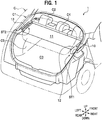
- the vehicle C has a vehicle body style like a wagon, a minivan, or the like in which a vehicle cabin can be accessed from the vehicle rear side by opening and closing a tailgate C1.
- a luggage compartment C3 is defined behind a rearmost seat C2 which is a seat located behind all other seats in the vehicle cabin.
- the luggage compartment C3 is sectioned and defined on four sides by a backrest C4 of the rearmost seat C2 and a tail gate C1 in a front-rear direction and by left and right side walls C5.
- the tonneau cover 1 for the vehicle covers luggage when the luggage is loaded on the aforementioned luggage compartment C3 and thereby improves the appearance when the inside of the vehicle is viewed from the tailgate C1 or the like.
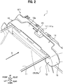
- the tonneau cover 1 for the vehicle in the embodiment includes a device main body 10, an attachment structure ST1, and a lock structure ST2.
- the device main body 10 is detachably attached to the vehicle body via the attachment structure ST1. As illustrated in FIGs. 1 and 2 , the device main body 10 includes a cover body 11, a roll-up device 12, handle unit 13, and main body-side attachment unit 14.
- main body-side attachment unit 14 and the roll-up device 12 are housed in a main body case 15.
- the main body-side attachment unit 14 and the roll-up device 12 can be thereby handled as one unit.
- the cover body 11 is formed of a sheet-like member flexible enough to be rolled up like a cloth. Moreover, the cover body 11 is rolled up in a state where a base end portion of the cover body 11 in a roll-up direction X is supported by the roll-up device 12 and the cover body 11 can be freely pulled out from the inside of the roll-up device 12.
- the handle unit 13 is arranged in a distal end portion of the cover body 11 in the roll-up direction X.
- the base end portion of the cover body 11 is supported by a roll-up rod (not illustrated) rotatably supported on the main body case 15.
- the roll-up device 12 rolls up the cover body 11 around the roll-up rod to house it by biasing the roll-up rod in the roll-up direction X.
- the handle unit 13 functions as a handle when the cover body 11 rolled up in the roll-up device 12 is pulled out and spread.
- the handle unit 13 includes a handle base 131, a handle 132, and handle-side lock portions 133.
- the handle base 131 has a substantially T shape formed by a large-width portion 131a and a small-width portion 131b.
- the large-width portion 131a is provided in the distal end portion of the cover body 11 and the width dimension of the large-width portion 131a is set to be equivalent to the width dimension of the cover body 11. Moreover, the large-width portion 131a supports the distal end portion of the cover body 11 such that the distal end portion is held between parts of the large-width portion 131a over the entire width of the cover body 11.
- the width dimension of the small-width portion 131b is set to be smaller than that of the large-width portion 131a.
- the handle 132 is arranged on an upper surface of the small-width portion 131b and the handle-side lock portions 133 are provided in both end portions of the small-width portion 131b.
- the handle 132 includes paired handle legs 132a standing up from the front and rear end portions of the small-width portion 131b and a grip portion 132b connecting upper end portions of the handle legs 132a to each other while extending parallel to the handle base 131.
- the handle 132 has a frame-like substantially trapezoidal shape formed by the handle legs 132a and the grip portion 132b.
- the handle-side lock portions 133 constitute the lock structure ST2 and are formed of substantially cylindrical protrusions protruding from both ends of the small-width portion 131b to extend along a longitudinal direction of the handle base 131.
- the main body-side attachment unit 14 constitutes the attachment structure ST1 together with vehicle body-side attachment portions 20 and detachably attaches the device main body 10 to the vehicle body (vehicle body-side attachment portion 20) .
- the main body-side attachment unit 14 includes an operation lever 141, sliders 142, a link 143, and a torsion coil spring 144 (link biasing unit) .
- the operation lever 141 is arranged to be slidable on a top plate 15a of the main body case 15. Moreover, the operation lever 141 includes an operation portion 141a and lever legs 141b.
- the operation portion 141a is a portion operated by an operator when the device main body 10 is to be removed from the vehicle body (vehicle body-side attachment portion 20), and has a substantially truncated quadrilateral pyramid shape.
- the lever legs 141b are elastic plate-shaped members extending downward from a lower surface of the operation portion 141a and include triangular protrusions 141c at their distal ends. Moreover, the lever legs 141b are inserted and fitted into a lever hole 15b which is an elongated hole opened in the top plate 15a of the main body case 15 and extending along the longitudinal direction of the main body case 15.
- the sliders 142 include a directly-driven slider 142D and a following slider 142F.
- the directly-driven slider 142D and the following slider 142F each include a slider engagement portion 142a, a link protrusion 142b, and an elongated guide hole 142c.
- the slider engagement portion 142a is formed in a distal end portion of each slider 142. Moreover, the slider engagement portion 142a has a tapered shape with an acute angle formed by a tilted surface 142aa obliquely tilted with respect to an attachment direction (vertical direction) and an engagement surface 142ab orthogonal to the attachment direction.
- the link protrusion 142b is formed in a base end portion of each slider 142 and is formed of a cylindrical protrusion which can be linked to the link 143.
- the elongated guide hole 142c is described together with guide unit 16 to be described later.
- the directly-driven slider 142D is linked to the operation lever 141 via a not-illustrated link structure and is moved between an engagement position and a release position in conjunction with a sliding operation performed on the operation lever 141.
- the engagement position is a position where the slider engagement portion 142a protruding from the main body case 15 can engage with a lever receiving hole 20a to be described later.
- the release position is a position where the slider engagement portion 142a is housed in the main body case 15 and cannot engage with the lever receiving hole 20a.
- the link 143 includes a link main body 143a, a link shaft 143b, and link holes 143c.
- the link main body 143a is formed of a rectangular plate member.
- the link shaft 143b is formed of a cylindrical shaft member standing perpendicular to a plate surface in a center portion of the link main body 143a and is turnably supported on the main body case 15.
- the link holes 143c are paired elongated holes provided on both sides of the link shaft 143b to penetrate the plate surface and extend along the longitudinal direction of the link main body 143a.
- the link protrusions 142b of the sliders 142 are inserted respectively into the link holes 143c.
- the link 143 converts a turning motion of the link 143 about the link shaft 143b into a linear motion of the sliders 142 by means of linkage between the link holes 143c and the link protrusions 142b.
- the torsion coil spring 144 includes a coil portion 144a which is a linear spring member wound in a cylindrical shape and paired arms 144b extending from both ends of the coil portion 144a.
- the coil portion 144a is wound around the link shaft 143b supporting the link 143.
- One of the paired arms 144b engages with a peripheral wall of the link main body 143a and the other one engages with the main body case 15.
- the torsion coil spring 144 keeps the link 143 biased to turn from the release position side toward the engagement position side (clockwise in FIG. 5 ) . Then, the link 143 biases the operation lever 141 and both sliders 142 from the release position side toward the engagement position side. Specifically, the torsion coil spring 144 biases both sliders 142 in such directions that the sliders 142 protrude out from the main body case 15.
- the guide unit 16 is a configuration for guiding the sliders 142 such that the sliders 142 slide smoothly between the engagement position and the release position without being caught.
- the guide unit 16 includes guide pins 161, the elongated guide holes 142c, and guide walls 162.
- the elongated guide holes 142c are elongated holes penetrating the plate surfaces of the sliders 142 and define movement ranges (strokes) of the sliders 142.
- the guide pins 161 stand from the main body case 15 to extend orthogonal to the slide direction, through the elongated guide holes 142c.
- the guide walls 162 come into contact with upper and lower edges of the sliders 142 and are arranged opposite to each other while extending along the slide direction.
- the main body case 15 includes a cushion member 15c on an outer bottom surface.
- the cushion member 15c absorbs vibration in traveling of the vehicle such that the main body case 15 does not rattle due to the vibration.
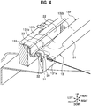
- the vehicle body-side attachment portions 20 are vehicle body-side portions configured to receive the main body-side attachment unit 14 and are formed in wall step portions 21.
- the wall step portions 21 are formed of step portions extending in the vehicle front-rear direction in the respective side walls C5 of the luggage compartment C3, at a height of the backrest of the rearmost seat C2.
- a center portion of each wall step portion 21 there is formed a wall step recess portion 22 recessed with respect to a corner portion between a step portion top surface 21a and a step portion side surface 21b.
- a center recess portion 23 recessed downward is formed in a bottom center portion of the wall step recess portion 22.
- the vehicle body-side attachment portion 20 includes lever receiving holes 20a and center step corner portions 20b.
- the lever receiving holes 20a are opened in a front wall 23a and a rear wall 23b constituting vertical walls of the center recess portion 23.
- the hole shape of the lever receiving holes 20a is formed in the same shape as the slider engagement portions 142a.
- Each center step corner portion 20b is a corner portion between the vertical wall (front wall 23a, rear wall 23b) of the center recess portion 23 and a bottom surface 22a of the wall step recess portion 22.
- Vehicle body-side lock portions 30 constituting the lock structure ST2 are formed in a bottom front end portion and a bottom rear end portion of the wall step recess portion 22.
- the lock structure ST2 is formed of the vehicle body-side lock portions 30 and the aforementioned handle-side lock portions 133.
- each vehicle body-side lock portion 30 includes a lock base portion 31 and a lock arm 32.
- the lock base portion 31 is formed of a protrusion standing from the bottom surface 22a of the wall step recess portion 22 toward the vehicle upper side.
- the lock arm 32 is formed of a cantilever beam-shaped protrusion extending from the inside toward the outside in the vehicle width direction in a distal end portion of the lock base portion 31.
- each vehicle body-side lock portion 30 has a substantially inverted L-shape formed by the lock base portion 31 and the lock arm 32.
- the handle-side lock portion 133 of the handle unit 13 is locked to the inside of the L-shape.
- a receiving surface 33 is set on a top surface of the lock arm 32.
- the receiving surface 33 is configured to support the main body case 15 when the device main body 10 is attached to the wall step recess portion 22.
- the vehicle body-side attachment portion 20 includes the receiving surfaces 33 which support the roll-up device 12 by coming into contact therewith and the vehicle body-side lock portions 30 are formed on the back side of the receiving surfaces 33.
- vehicle body-side lock portions 30 are formed in a portion (wall step recess portion 22) where the vehicle body-side attachment portion 20 is arranged.
- the vehicle body-side attachment portion 20 and the vehicle body-side lock portions 30 have the same configurations in the left and right wall portions C5a, C5b.
- the main body-side attachment unit 14 can be detachably attached to either of the left or right vehicle body-side attachment portion 20 and the handle unit 13 can be locked to and unlocked from either of the left or right vehicle body-side lock portions 30.
- the link 143 is biased in a direction in which the link 143 is turned clockwise in FIG. 5 by biasing force of the torsion coil spring 144. Moreover, the biasing force applied to the link 143 acts on both sliders 142 via the link protrusions 142b. Furthermore, both sliders 142 are kept biased from the release position side to the engagement position by the biasing force.
- the slider engagement portions 142a of the respective sliders 142 are thereby kept protruding from the main body case 15.
- the protruding slider engagement portions 142a are inserted and fitted in the lever receiving holes 20a and the device main body 10 is fixed in a state housed in the wall step recess portion 22.
- the link 143 turns by means of the linkage between a directly-driven link protrusion 142bD and the link hole 143c.
- the link 143 turns, the following slider 142F slides by means of the linkage between the link hole 143c and a following link protrusion 142bF.
- the link 143 is turned by the basing force of the torsion coil spring 144 and the operation lever 141 and the sliders 142 are moved to the positions before the start of operation (engagement position) and are kept biased.
- the pushing force exceeds the basing force of the torsion coil spring 144 and the slider engagement portions 142a are made to retreat into the main body case 15 and are moved toward the release positions by component force in the sliding directions of the respective sliders 142 generated by the tilted surfaces 142aa.
- the slider engagement portions 142a retreat into the main body case 15, nothing hinders the fitting and the device main body 10 is set to a state where the device main body 10 can be inserted into the wall step recess portion 22.
- the vehicle body-side attachment portion 20 and the vehicle body-side lock portion 30 are arranged on each of the left and right side walls C5 (paired wall portions) arranged opposite to each other as the wall surfaces forming the luggage compartment C3.
- the roll-up device 12 can be thereby detachably attached to either one of the left or right side wall C5. Moreover, the handle 132 (handle unit 13) can be locked to and unlocked from the other wall portion C5b opposite to the one wall portion C5a to which the roll-up device 12 is attached.
- the cover body 11 can be pulled out and spread from either of the left or right side wall C5, the convenience can be improved.
- the vehicle body-side lock portions 30 are formed in the wall step recess portions 22 which are portions in which the vehicle body-side attachment portions 20 are arranged.
- the tonneau cover 1 for the vehicle with excellent convenience can be thereby installed in a smaller installation space.
- the vehicle body-side attachment portions 20 include the receiving surfaces 33 which come into contact with the device main body 10 including the roll-up device 12 to support it, and the vehicle body-side lock portions 30 are formed on the back side of the receiving surfaces 33.
- the tonneau cover 1 for the vehicle with excellent convenience can be thereby stably installed without an increase in the installation space.
- tonneau cover 1 for the vehicle in the embodiment has such a configuration that the operation lever 141 turns the link 143 and causes both sliders 142 to slide, the present invention is not limited to this configuration.
- the configuration may be such that both arms 144b of the torsion coil spring 144 are linked to the respective sliders 142 without the link 143 therebetween and the biasing force of the torsion coil spring 144 is directly applied to the sliders 142.
- the tonneau cover 1 for the vehicle in the embodiment has such a configuration that the operation portion 141a, the sliders 142, and the link 143 are arranged in the main body case 15 and the slider engagement portions 142a are inserted and fitted into the lever receiving holes 20a on the vehicle side, the present invention is not limited to this configuration.
- the configuration may be such that the lever receiving holes are provided in the main body case and the operation lever, the sliders, and the link are arranged on the vehicle body side (wall step recess portions).
- any configuration can be employed as long as the configuration is such that the main body case 15 can be detachably attached to the vehicle body.
- the tonneau cover 1 for the vehicle in the embodiment has such a configuration that the columnar handle-side lock portions 133 are locked by being hooked to the vehicle body-side lock portions 30 with the inverted L shape, the present invention is not limited to this configuration.
- the configuration may be such that the handle-side lock portions 133 have a claw shape and are locked by being hooked to protrusions or recesses provided as the vehicle body-side lock portions 30.
- any configuration can be employed as long as the configuration is such that the handle 132 can be locked to and unlocked from the vehicle body.
Landscapes
- Engineering & Computer Science (AREA)
- Mechanical Engineering (AREA)
- Vehicle Step Arrangements And Article Storage (AREA)
Claims (1)
- Un compartiment à bagages pour un véhicule comprenant un couvre-tonneau qui comprend :un corps de couvercle flexible en forme de feuille (11) ;un dispositif d'enroulement (12) configuré pour enrouler le corps de couvercle (11) tout en supportant une extrémité du corps de couvercle (11) ; etune unité de poignée (13) disposée à une autre extrémité du corps de couvercle (11) et configurée pour servir de poignée lorsque le corps de couvercle (11) est tiré du dispositif d'enroulement (12), dans lequelle dispositif d'enroulement (12) est configuré pour pouvoir être fixé de manière détachable à l'une ou l'autre (C5a) des parties de paroi gauche et droite jumelées (C5a, C5b) disposées à l'opposé l'une de l'autre en tant que surfaces de paroi formant un compartiment à bagages (C3) du véhicule, etl'unité de poignée (13) peut être verrouillée à et déverrouillée de l'autre partie de paroi (C5b) opposée à ladite une partie de paroi (C5a) à laquelle le dispositif d'enroulement est fixé,caractérisé en ce queles parties de fixation (20) du côté du corps du véhicule et les parties de verrouillage (30) du côté du corps du véhicule ont les mêmes configurations dans les parties de paroi gauche et droite (C5a, C5b),le dispositif d'enroulement (12) est fixé de manière détachable à une des parties de fixation (20) du côté gauche ou droite du corps du véhicule disposées dans les parties de paroi jumelées respectives (C5a, C5b),l'unité de poignée (13) peut être verrouillée à et déverrouillée de l'une ou l'autre des parties de verrouillage gauche et droite du côté du corps du véhicule (30) formées dans des sections des parties de paroi jumelées respectives (C5a, C5b),les parties de verrouillage (30) du côté du corps du véhicule sont formées dans des sections où les parties de fixation (20) du côté du corps du véhicule sont disposées,les parties de fixation (20) du côté du corps du véhicule comprennent des surfaces de réception (33) configurées pour entrer en contact avec le dispositif d'enroulement (12) et supporter le dispositif d'enroulement (12), etles parties de verrouillage (30) du côté du corps du véhicule sont formées sur les côtés arrière des surfaces de réception (33).
Applications Claiming Priority (2)
| Application Number | Priority Date | Filing Date | Title |
|---|---|---|---|
| JP2016186007 | 2016-09-23 | ||
| PCT/JP2017/029017 WO2018055942A1 (fr) | 2016-09-23 | 2017-08-09 | Couvre-benne pour véhicule |
Publications (3)
| Publication Number | Publication Date |
|---|---|
| EP3517366A1 EP3517366A1 (fr) | 2019-07-31 |
| EP3517366A4 EP3517366A4 (fr) | 2019-07-31 |
| EP3517366B1 true EP3517366B1 (fr) | 2020-10-07 |
Family
ID=61690828
Family Applications (1)
| Application Number | Title | Priority Date | Filing Date |
|---|---|---|---|
| EP17852723.0A Not-in-force EP3517366B1 (fr) | 2016-09-23 | 2017-08-09 | Couvre-benne pour véhicule |
Country Status (5)
| Country | Link |
|---|---|
| US (1) | US10926706B2 (fr) |
| EP (1) | EP3517366B1 (fr) |
| JP (1) | JP6568661B2 (fr) |
| CN (1) | CN109789836A (fr) |
| WO (1) | WO2018055942A1 (fr) |
Family Cites Families (13)
| Publication number | Priority date | Publication date | Assignee | Title |
|---|---|---|---|---|
| US5213387A (en) | 1992-04-07 | 1993-05-25 | Takata, Inc. | Cross body motor vehicle security shade |
| JP3494314B2 (ja) * | 1994-06-17 | 2004-02-09 | 株式会社タケヒロ | 車両用トノカバー装置 |
| US5547187A (en) * | 1994-08-24 | 1996-08-20 | Prince Corporation | Multi-function cover |
| DE19544611C1 (de) * | 1995-11-30 | 1997-04-24 | Parat Werk Schoenenbach Gmbh | Seitlich ausziehbare Gepäckraumabdeckung |
| JPH09207676A (ja) * | 1996-02-02 | 1997-08-12 | Kasai Kogyo Co Ltd | 車両用トノカバー装置 |
| US5947358A (en) * | 1997-04-11 | 1999-09-07 | Irvin Automotive Products, Inc. | Side pull security shade with storage compartment |
| DE20211074U1 (de) * | 2002-07-22 | 2003-01-16 | Arslan, Seyit Mehmet, 20357 Hamburg | Kofferraumabdeckung |
| DE102004029042A1 (de) * | 2004-06-08 | 2005-12-29 | Bos Gmbh & Co. Kg | Schutzvorrichtung für einen Fahrzeuginnenraum |
| JP2006137307A (ja) * | 2004-11-12 | 2006-06-01 | Nissan Motor Co Ltd | 車両用ラゲッジルーム |
| DE102010022681A1 (de) * | 2010-06-04 | 2011-01-27 | Daimler Ag | Ablagevorrichtung für ein Kraftfahrzeug |
| EP2958773B2 (fr) * | 2013-02-21 | 2021-02-24 | Toyota Jidosha Kabushiki Kaisha | Dispositif de couvre-habitacle et système destiné à un véhicule |
| US9238438B1 (en) * | 2014-07-25 | 2016-01-19 | GM Global Technology Operations LLC | Laterally moving cargo shade and net |
| DE102015205771B3 (de) * | 2015-03-31 | 2016-07-28 | Bos Gmbh & Co. Kg | Laderaumabdeckung für einen Personenkraftwagen |
-
2017
- 2017-08-09 EP EP17852723.0A patent/EP3517366B1/fr not_active Not-in-force
- 2017-08-09 JP JP2018540909A patent/JP6568661B2/ja active Active
- 2017-08-09 US US16/335,369 patent/US10926706B2/en active Active
- 2017-08-09 WO PCT/JP2017/029017 patent/WO2018055942A1/fr not_active Ceased
- 2017-08-09 CN CN201780058987.4A patent/CN109789836A/zh active Pending
Non-Patent Citations (1)
| Title |
|---|
| None * |
Also Published As
| Publication number | Publication date |
|---|---|
| JPWO2018055942A1 (ja) | 2019-04-18 |
| JP6568661B2 (ja) | 2019-08-28 |
| US20190283678A1 (en) | 2019-09-19 |
| US10926706B2 (en) | 2021-02-23 |
| WO2018055942A1 (fr) | 2018-03-29 |
| EP3517366A1 (fr) | 2019-07-31 |
| EP3517366A4 (fr) | 2019-07-31 |
| CN109789836A (zh) | 2019-05-21 |
Similar Documents
| Publication | Publication Date | Title |
|---|---|---|
| US9434317B2 (en) | Vehicle step system | |
| CN102271965B (zh) | 用于收纳收卷式车厢盖布组件的行李室构造 | |
| CN204728845U (zh) | 机动车辆发动机罩闩锁机构和发动机罩闩锁 | |
| US20110241372A1 (en) | Tonneau cover device of vehicle | |
| US9211842B2 (en) | Cargo floor for a vehicle | |
| CN108791090B (zh) | 用于机动车辆的货舱组件 | |
| US20160159258A1 (en) | Console armrest assembly with dampening strut and integrated inertial lock | |
| US20210370840A1 (en) | Lock device for opening/closing body | |
| JP6348527B2 (ja) | 車体後部構造 | |
| EP3517366B1 (fr) | Couvre-benne pour véhicule | |
| CZ2021300A3 (cs) | Sestava pro zakrývání zavazadlového prostoru | |
| JP5985234B2 (ja) | シート部材固定用留め具 | |
| KR101519247B1 (ko) | 슬라이드 도어 장치 | |
| CN107585109B (zh) | 用于车辆的托架设备 | |
| KR101712278B1 (ko) | 자동차용 시트 등받이 각도 해제 장치 | |
| JP5047521B2 (ja) | 車両用ルーフロック装置 | |
| JP2015081016A (ja) | 車両用荷室構造 | |
| CN110785324A (zh) | 用于致动机动车辆行李箱行李盖横向件到锁紧位置的系统 | |
| JP6311536B2 (ja) | 車両の後部車体構造 | |
| JP5151238B2 (ja) | 車体補強構造 | |
| KR101875434B1 (ko) | 차량용 커버링 쉘프 | |
| JP5625803B2 (ja) | 車両用トノカバー | |
| EP2944749A1 (fr) | Mécanisme de verrouillage | |
| JP4871623B2 (ja) | 車両用ルーフロック装置 | |
| KR100569344B1 (ko) | 자동차 리어시트백의 다용도 스크린 장치 |
Legal Events
| Date | Code | Title | Description |
|---|---|---|---|
| STAA | Information on the status of an ep patent application or granted ep patent |
Free format text: STATUS: THE INTERNATIONAL PUBLICATION HAS BEEN MADE |
|
| PUAI | Public reference made under article 153(3) epc to a published international application that has entered the european phase |
Free format text: ORIGINAL CODE: 0009012 |
|
| STAA | Information on the status of an ep patent application or granted ep patent |
Free format text: STATUS: REQUEST FOR EXAMINATION WAS MADE |
|
| 17P | Request for examination filed |
Effective date: 20190418 |
|
| A4 | Supplementary search report drawn up and despatched |
Effective date: 20190531 |
|
| AK | Designated contracting states |
Kind code of ref document: A1 Designated state(s): AL AT BE BG CH CY CZ DE DK EE ES FI FR GB GR HR HU IE IS IT LI LT LU LV MC MK MT NL NO PL PT RO RS SE SI SK SM TR |
|
| AX | Request for extension of the european patent |
Extension state: BA ME |
|
| DAV | Request for validation of the european patent (deleted) | ||
| DAX | Request for extension of the european patent (deleted) | ||
| STAA | Information on the status of an ep patent application or granted ep patent |
Free format text: STATUS: EXAMINATION IS IN PROGRESS |
|
| 17Q | First examination report despatched |
Effective date: 20200129 |
|
| GRAP | Despatch of communication of intention to grant a patent |
Free format text: ORIGINAL CODE: EPIDOSNIGR1 |
|
| STAA | Information on the status of an ep patent application or granted ep patent |
Free format text: STATUS: GRANT OF PATENT IS INTENDED |
|
| INTG | Intention to grant announced |
Effective date: 20200414 |
|
| GRAS | Grant fee paid |
Free format text: ORIGINAL CODE: EPIDOSNIGR3 |
|
| GRAA | (expected) grant |
Free format text: ORIGINAL CODE: 0009210 |
|
| STAA | Information on the status of an ep patent application or granted ep patent |
Free format text: STATUS: THE PATENT HAS BEEN GRANTED |
|
| AK | Designated contracting states |
Kind code of ref document: B1 Designated state(s): AL AT BE BG CH CY CZ DE DK EE ES FI FR GB GR HR HU IE IS IT LI LT LU LV MC MK MT NL NO PL PT RO RS SE SI SK SM TR |
|
| REG | Reference to a national code |
Ref country code: GB Ref legal event code: FG4D |
|
| REG | Reference to a national code |
Ref country code: CH Ref legal event code: EP Ref country code: AT Ref legal event code: REF Ref document number: 1320860 Country of ref document: AT Kind code of ref document: T Effective date: 20201015 |
|
| REG | Reference to a national code |
Ref country code: IE Ref legal event code: FG4D |
|
| REG | Reference to a national code |
Ref country code: DE Ref legal event code: R096 Ref document number: 602017025224 Country of ref document: DE |
|
| REG | Reference to a national code |
Ref country code: NL Ref legal event code: MP Effective date: 20201007 |
|
| REG | Reference to a national code |
Ref country code: AT Ref legal event code: MK05 Ref document number: 1320860 Country of ref document: AT Kind code of ref document: T Effective date: 20201007 |
|
| PG25 | Lapsed in a contracting state [announced via postgrant information from national office to epo] |
Ref country code: GR Free format text: LAPSE BECAUSE OF FAILURE TO SUBMIT A TRANSLATION OF THE DESCRIPTION OR TO PAY THE FEE WITHIN THE PRESCRIBED TIME-LIMIT Effective date: 20210108 Ref country code: NO Free format text: LAPSE BECAUSE OF FAILURE TO SUBMIT A TRANSLATION OF THE DESCRIPTION OR TO PAY THE FEE WITHIN THE PRESCRIBED TIME-LIMIT Effective date: 20210107 Ref country code: PT Free format text: LAPSE BECAUSE OF FAILURE TO SUBMIT A TRANSLATION OF THE DESCRIPTION OR TO PAY THE FEE WITHIN THE PRESCRIBED TIME-LIMIT Effective date: 20210208 Ref country code: RS Free format text: LAPSE BECAUSE OF FAILURE TO SUBMIT A TRANSLATION OF THE DESCRIPTION OR TO PAY THE FEE WITHIN THE PRESCRIBED TIME-LIMIT Effective date: 20201007 Ref country code: FI Free format text: LAPSE BECAUSE OF FAILURE TO SUBMIT A TRANSLATION OF THE DESCRIPTION OR TO PAY THE FEE WITHIN THE PRESCRIBED TIME-LIMIT Effective date: 20201007 |
|
| REG | Reference to a national code |
Ref country code: LT Ref legal event code: MG4D |
|
| PG25 | Lapsed in a contracting state [announced via postgrant information from national office to epo] |
Ref country code: BG Free format text: LAPSE BECAUSE OF FAILURE TO SUBMIT A TRANSLATION OF THE DESCRIPTION OR TO PAY THE FEE WITHIN THE PRESCRIBED TIME-LIMIT Effective date: 20210107 Ref country code: LV Free format text: LAPSE BECAUSE OF FAILURE TO SUBMIT A TRANSLATION OF THE DESCRIPTION OR TO PAY THE FEE WITHIN THE PRESCRIBED TIME-LIMIT Effective date: 20201007 Ref country code: PL Free format text: LAPSE BECAUSE OF FAILURE TO SUBMIT A TRANSLATION OF THE DESCRIPTION OR TO PAY THE FEE WITHIN THE PRESCRIBED TIME-LIMIT Effective date: 20201007 Ref country code: IS Free format text: LAPSE BECAUSE OF FAILURE TO SUBMIT A TRANSLATION OF THE DESCRIPTION OR TO PAY THE FEE WITHIN THE PRESCRIBED TIME-LIMIT Effective date: 20210207 Ref country code: SE Free format text: LAPSE BECAUSE OF FAILURE TO SUBMIT A TRANSLATION OF THE DESCRIPTION OR TO PAY THE FEE WITHIN THE PRESCRIBED TIME-LIMIT Effective date: 20201007 Ref country code: ES Free format text: LAPSE BECAUSE OF FAILURE TO SUBMIT A TRANSLATION OF THE DESCRIPTION OR TO PAY THE FEE WITHIN THE PRESCRIBED TIME-LIMIT Effective date: 20201007 Ref country code: AT Free format text: LAPSE BECAUSE OF FAILURE TO SUBMIT A TRANSLATION OF THE DESCRIPTION OR TO PAY THE FEE WITHIN THE PRESCRIBED TIME-LIMIT Effective date: 20201007 |
|
| PG25 | Lapsed in a contracting state [announced via postgrant information from national office to epo] |
Ref country code: HR Free format text: LAPSE BECAUSE OF FAILURE TO SUBMIT A TRANSLATION OF THE DESCRIPTION OR TO PAY THE FEE WITHIN THE PRESCRIBED TIME-LIMIT Effective date: 20201007 Ref country code: NL Free format text: LAPSE BECAUSE OF FAILURE TO SUBMIT A TRANSLATION OF THE DESCRIPTION OR TO PAY THE FEE WITHIN THE PRESCRIBED TIME-LIMIT Effective date: 20201007 |
|
| REG | Reference to a national code |
Ref country code: DE Ref legal event code: R097 Ref document number: 602017025224 Country of ref document: DE |
|
| PG25 | Lapsed in a contracting state [announced via postgrant information from national office to epo] |
Ref country code: SM Free format text: LAPSE BECAUSE OF FAILURE TO SUBMIT A TRANSLATION OF THE DESCRIPTION OR TO PAY THE FEE WITHIN THE PRESCRIBED TIME-LIMIT Effective date: 20201007 Ref country code: EE Free format text: LAPSE BECAUSE OF FAILURE TO SUBMIT A TRANSLATION OF THE DESCRIPTION OR TO PAY THE FEE WITHIN THE PRESCRIBED TIME-LIMIT Effective date: 20201007 Ref country code: CZ Free format text: LAPSE BECAUSE OF FAILURE TO SUBMIT A TRANSLATION OF THE DESCRIPTION OR TO PAY THE FEE WITHIN THE PRESCRIBED TIME-LIMIT Effective date: 20201007 Ref country code: LT Free format text: LAPSE BECAUSE OF FAILURE TO SUBMIT A TRANSLATION OF THE DESCRIPTION OR TO PAY THE FEE WITHIN THE PRESCRIBED TIME-LIMIT Effective date: 20201007 Ref country code: SK Free format text: LAPSE BECAUSE OF FAILURE TO SUBMIT A TRANSLATION OF THE DESCRIPTION OR TO PAY THE FEE WITHIN THE PRESCRIBED TIME-LIMIT Effective date: 20201007 Ref country code: RO Free format text: LAPSE BECAUSE OF FAILURE TO SUBMIT A TRANSLATION OF THE DESCRIPTION OR TO PAY THE FEE WITHIN THE PRESCRIBED TIME-LIMIT Effective date: 20201007 |
|
| PLBE | No opposition filed within time limit |
Free format text: ORIGINAL CODE: 0009261 |
|
| STAA | Information on the status of an ep patent application or granted ep patent |
Free format text: STATUS: NO OPPOSITION FILED WITHIN TIME LIMIT |
|
| REG | Reference to a national code |
Ref country code: DE Ref legal event code: R084 Ref document number: 602017025224 Country of ref document: DE |
|
| PG25 | Lapsed in a contracting state [announced via postgrant information from national office to epo] |
Ref country code: DK Free format text: LAPSE BECAUSE OF FAILURE TO SUBMIT A TRANSLATION OF THE DESCRIPTION OR TO PAY THE FEE WITHIN THE PRESCRIBED TIME-LIMIT Effective date: 20201007 |
|
| 26N | No opposition filed |
Effective date: 20210708 |
|
| PG25 | Lapsed in a contracting state [announced via postgrant information from national office to epo] |
Ref country code: AL Free format text: LAPSE BECAUSE OF FAILURE TO SUBMIT A TRANSLATION OF THE DESCRIPTION OR TO PAY THE FEE WITHIN THE PRESCRIBED TIME-LIMIT Effective date: 20201007 Ref country code: IT Free format text: LAPSE BECAUSE OF FAILURE TO SUBMIT A TRANSLATION OF THE DESCRIPTION OR TO PAY THE FEE WITHIN THE PRESCRIBED TIME-LIMIT Effective date: 20201007 |
|
| PG25 | Lapsed in a contracting state [announced via postgrant information from national office to epo] |
Ref country code: SI Free format text: LAPSE BECAUSE OF FAILURE TO SUBMIT A TRANSLATION OF THE DESCRIPTION OR TO PAY THE FEE WITHIN THE PRESCRIBED TIME-LIMIT Effective date: 20201007 |
|
| REG | Reference to a national code |
Ref country code: CH Ref legal event code: PL |
|
| PG25 | Lapsed in a contracting state [announced via postgrant information from national office to epo] |
Ref country code: MC Free format text: LAPSE BECAUSE OF FAILURE TO SUBMIT A TRANSLATION OF THE DESCRIPTION OR TO PAY THE FEE WITHIN THE PRESCRIBED TIME-LIMIT Effective date: 20201007 |
|
| REG | Reference to a national code |
Ref country code: BE Ref legal event code: MM Effective date: 20210831 |
|
| GBPC | Gb: european patent ceased through non-payment of renewal fee |
Effective date: 20210809 |
|
| PG25 | Lapsed in a contracting state [announced via postgrant information from national office to epo] |
Ref country code: LI Free format text: LAPSE BECAUSE OF NON-PAYMENT OF DUE FEES Effective date: 20210831 Ref country code: CH Free format text: LAPSE BECAUSE OF NON-PAYMENT OF DUE FEES Effective date: 20210831 |
|
| PG25 | Lapsed in a contracting state [announced via postgrant information from national office to epo] |
Ref country code: IS Free format text: LAPSE BECAUSE OF FAILURE TO SUBMIT A TRANSLATION OF THE DESCRIPTION OR TO PAY THE FEE WITHIN THE PRESCRIBED TIME-LIMIT Effective date: 20210207 Ref country code: LU Free format text: LAPSE BECAUSE OF NON-PAYMENT OF DUE FEES Effective date: 20210809 |
|
| PG25 | Lapsed in a contracting state [announced via postgrant information from national office to epo] |
Ref country code: IE Free format text: LAPSE BECAUSE OF NON-PAYMENT OF DUE FEES Effective date: 20210809 Ref country code: GB Free format text: LAPSE BECAUSE OF NON-PAYMENT OF DUE FEES Effective date: 20210809 Ref country code: FR Free format text: LAPSE BECAUSE OF NON-PAYMENT OF DUE FEES Effective date: 20210831 Ref country code: BE Free format text: LAPSE BECAUSE OF NON-PAYMENT OF DUE FEES Effective date: 20210831 |
|
| PG25 | Lapsed in a contracting state [announced via postgrant information from national office to epo] |
Ref country code: CY Free format text: LAPSE BECAUSE OF FAILURE TO SUBMIT A TRANSLATION OF THE DESCRIPTION OR TO PAY THE FEE WITHIN THE PRESCRIBED TIME-LIMIT Effective date: 20201007 |
|
| PG25 | Lapsed in a contracting state [announced via postgrant information from national office to epo] |
Ref country code: HU Free format text: LAPSE BECAUSE OF FAILURE TO SUBMIT A TRANSLATION OF THE DESCRIPTION OR TO PAY THE FEE WITHIN THE PRESCRIBED TIME-LIMIT; INVALID AB INITIO Effective date: 20170809 |
|
| PG25 | Lapsed in a contracting state [announced via postgrant information from national office to epo] |
Ref country code: MK Free format text: LAPSE BECAUSE OF FAILURE TO SUBMIT A TRANSLATION OF THE DESCRIPTION OR TO PAY THE FEE WITHIN THE PRESCRIBED TIME-LIMIT Effective date: 20201007 |
|
| PG25 | Lapsed in a contracting state [announced via postgrant information from national office to epo] |
Ref country code: TR Free format text: LAPSE BECAUSE OF FAILURE TO SUBMIT A TRANSLATION OF THE DESCRIPTION OR TO PAY THE FEE WITHIN THE PRESCRIBED TIME-LIMIT Effective date: 20201007 |
|
| PG25 | Lapsed in a contracting state [announced via postgrant information from national office to epo] |
Ref country code: MT Free format text: LAPSE BECAUSE OF FAILURE TO SUBMIT A TRANSLATION OF THE DESCRIPTION OR TO PAY THE FEE WITHIN THE PRESCRIBED TIME-LIMIT Effective date: 20201007 |
|
| PGFP | Annual fee paid to national office [announced via postgrant information from national office to epo] |
Ref country code: DE Payment date: 20240723 Year of fee payment: 8 |
|
| REG | Reference to a national code |
Ref country code: DE Ref legal event code: R119 Ref document number: 602017025224 Country of ref document: DE |