EP3517832A1 - Frontscheinwerfer für fahrzeug - Google Patents
Frontscheinwerfer für fahrzeug Download PDFInfo
- Publication number
- EP3517832A1 EP3517832A1 EP17852991.3A EP17852991A EP3517832A1 EP 3517832 A1 EP3517832 A1 EP 3517832A1 EP 17852991 A EP17852991 A EP 17852991A EP 3517832 A1 EP3517832 A1 EP 3517832A1
- Authority
- EP
- European Patent Office
- Prior art keywords
- reflector
- movable
- movable shade
- shade
- mode
- Prior art date
- Legal status (The legal status is an assumption and is not a legal conclusion. Google has not performed a legal analysis and makes no representation as to the accuracy of the status listed.)
- Withdrawn
Links
- 238000009826 distribution Methods 0.000 claims description 56
- 238000003780 insertion Methods 0.000 claims description 21
- 230000037431 insertion Effects 0.000 claims description 21
- 230000002093 peripheral effect Effects 0.000 claims description 6
- 230000001105 regulatory effect Effects 0.000 description 33
- 230000007246 mechanism Effects 0.000 description 27
- 230000015572 biosynthetic process Effects 0.000 description 14
- 230000003287 optical effect Effects 0.000 description 14
- 238000000465 moulding Methods 0.000 description 12
- 230000033001 locomotion Effects 0.000 description 11
- 238000005520 cutting process Methods 0.000 description 5
- 230000017525 heat dissipation Effects 0.000 description 5
- 229910052751 metal Inorganic materials 0.000 description 5
- 239000002184 metal Substances 0.000 description 5
- 239000011347 resin Substances 0.000 description 5
- 229920005989 resin Polymers 0.000 description 5
- 238000003825 pressing Methods 0.000 description 4
- NJPPVKZQTLUDBO-UHFFFAOYSA-N novaluron Chemical compound C1=C(Cl)C(OC(F)(F)C(OC(F)(F)F)F)=CC=C1NC(=O)NC(=O)C1=C(F)C=CC=C1F NJPPVKZQTLUDBO-UHFFFAOYSA-N 0.000 description 3
- 230000000149 penetrating effect Effects 0.000 description 3
- 229910052782 aluminium Inorganic materials 0.000 description 2
- XAGFODPZIPBFFR-UHFFFAOYSA-N aluminium Chemical compound [Al] XAGFODPZIPBFFR-UHFFFAOYSA-N 0.000 description 2
- 238000005452 bending Methods 0.000 description 2
- 230000004907 flux Effects 0.000 description 2
- 229910000831 Steel Inorganic materials 0.000 description 1
- 230000004308 accommodation Effects 0.000 description 1
- 230000005540 biological transmission Effects 0.000 description 1
- 230000001276 controlling effect Effects 0.000 description 1
- 238000009434 installation Methods 0.000 description 1
- 230000001678 irradiating effect Effects 0.000 description 1
- 230000004048 modification Effects 0.000 description 1
- 238000012986 modification Methods 0.000 description 1
- 238000005549 size reduction Methods 0.000 description 1
- 239000010959 steel Substances 0.000 description 1
- 238000003466 welding Methods 0.000 description 1
Images


Classifications
-
- F—MECHANICAL ENGINEERING; LIGHTING; HEATING; WEAPONS; BLASTING
- F21—LIGHTING
- F21S—NON-PORTABLE LIGHTING DEVICES; SYSTEMS THEREOF; VEHICLE LIGHTING DEVICES SPECIALLY ADAPTED FOR VEHICLE EXTERIORS
- F21S41/00—Illuminating devices specially adapted for vehicle exteriors, e.g. headlamps
-
- F—MECHANICAL ENGINEERING; LIGHTING; HEATING; WEAPONS; BLASTING
- F21—LIGHTING
- F21S—NON-PORTABLE LIGHTING DEVICES; SYSTEMS THEREOF; VEHICLE LIGHTING DEVICES SPECIALLY ADAPTED FOR VEHICLE EXTERIORS
- F21S41/00—Illuminating devices specially adapted for vehicle exteriors, e.g. headlamps
- F21S41/30—Illuminating devices specially adapted for vehicle exteriors, e.g. headlamps characterised by reflectors
- F21S41/32—Optical layout thereof
- F21S41/36—Combinations of two or more separate reflectors
- F21S41/365—Combinations of two or more separate reflectors successively reflecting the light
-
- F—MECHANICAL ENGINEERING; LIGHTING; HEATING; WEAPONS; BLASTING
- F21—LIGHTING
- F21S—NON-PORTABLE LIGHTING DEVICES; SYSTEMS THEREOF; VEHICLE LIGHTING DEVICES SPECIALLY ADAPTED FOR VEHICLE EXTERIORS
- F21S41/00—Illuminating devices specially adapted for vehicle exteriors, e.g. headlamps
- F21S41/60—Illuminating devices specially adapted for vehicle exteriors, e.g. headlamps characterised by a variable light distribution
- F21S41/67—Illuminating devices specially adapted for vehicle exteriors, e.g. headlamps characterised by a variable light distribution by acting on reflectors
- F21S41/675—Illuminating devices specially adapted for vehicle exteriors, e.g. headlamps characterised by a variable light distribution by acting on reflectors by moving reflectors
-
- F—MECHANICAL ENGINEERING; LIGHTING; HEATING; WEAPONS; BLASTING
- F21—LIGHTING
- F21S—NON-PORTABLE LIGHTING DEVICES; SYSTEMS THEREOF; VEHICLE LIGHTING DEVICES SPECIALLY ADAPTED FOR VEHICLE EXTERIORS
- F21S41/00—Illuminating devices specially adapted for vehicle exteriors, e.g. headlamps
- F21S41/60—Illuminating devices specially adapted for vehicle exteriors, e.g. headlamps characterised by a variable light distribution
- F21S41/68—Illuminating devices specially adapted for vehicle exteriors, e.g. headlamps characterised by a variable light distribution by acting on screens
- F21S41/683—Illuminating devices specially adapted for vehicle exteriors, e.g. headlamps characterised by a variable light distribution by acting on screens by moving screens
- F21S41/689—Flaps, i.e. screens pivoting around one of their edges
-
- F—MECHANICAL ENGINEERING; LIGHTING; HEATING; WEAPONS; BLASTING
- F21—LIGHTING
- F21S—NON-PORTABLE LIGHTING DEVICES; SYSTEMS THEREOF; VEHICLE LIGHTING DEVICES SPECIALLY ADAPTED FOR VEHICLE EXTERIORS
- F21S43/00—Signalling devices specially adapted for vehicle exteriors, e.g. brake lamps, direction indicator lights or reversing lights
-
- F—MECHANICAL ENGINEERING; LIGHTING; HEATING; WEAPONS; BLASTING
- F21—LIGHTING
- F21S—NON-PORTABLE LIGHTING DEVICES; SYSTEMS THEREOF; VEHICLE LIGHTING DEVICES SPECIALLY ADAPTED FOR VEHICLE EXTERIORS
- F21S45/00—Arrangements within vehicle lighting devices specially adapted for vehicle exteriors, for purposes other than emission or distribution of light
-
- F—MECHANICAL ENGINEERING; LIGHTING; HEATING; WEAPONS; BLASTING
- F21—LIGHTING
- F21S—NON-PORTABLE LIGHTING DEVICES; SYSTEMS THEREOF; VEHICLE LIGHTING DEVICES SPECIALLY ADAPTED FOR VEHICLE EXTERIORS
- F21S41/00—Illuminating devices specially adapted for vehicle exteriors, e.g. headlamps
- F21S41/10—Illuminating devices specially adapted for vehicle exteriors, e.g. headlamps characterised by the light source
- F21S41/14—Illuminating devices specially adapted for vehicle exteriors, e.g. headlamps characterised by the light source characterised by the type of light source
- F21S41/141—Light emitting diodes [LED]
- F21S41/147—Light emitting diodes [LED] the main emission direction of the LED being angled to the optical axis of the illuminating device
-
- F—MECHANICAL ENGINEERING; LIGHTING; HEATING; WEAPONS; BLASTING
- F21—LIGHTING
- F21S—NON-PORTABLE LIGHTING DEVICES; SYSTEMS THEREOF; VEHICLE LIGHTING DEVICES SPECIALLY ADAPTED FOR VEHICLE EXTERIORS
- F21S41/00—Illuminating devices specially adapted for vehicle exteriors, e.g. headlamps
- F21S41/30—Illuminating devices specially adapted for vehicle exteriors, e.g. headlamps characterised by reflectors
- F21S41/39—Attachment thereof
-
- F—MECHANICAL ENGINEERING; LIGHTING; HEATING; WEAPONS; BLASTING
- F21—LIGHTING
- F21S—NON-PORTABLE LIGHTING DEVICES; SYSTEMS THEREOF; VEHICLE LIGHTING DEVICES SPECIALLY ADAPTED FOR VEHICLE EXTERIORS
- F21S45/00—Arrangements within vehicle lighting devices specially adapted for vehicle exteriors, for purposes other than emission or distribution of light
- F21S45/40—Cooling of lighting devices
- F21S45/47—Passive cooling, e.g. using fins, thermal conductive elements or openings
Definitions
- the disclosure relates to a vehicle headlamp.
- an auxiliary reflector is provided in a lamp chamber to compensate the travelling-beam light distribution.
- the size of the lamp can be reduced, as compared with a lamp structure in which two types of light source units having different specifications for a low beam and a travelling beam are accommodated in a lamp chamber.
- a high luminous flux corresponding LED Light Emitting Diode
- LED Light Emitting Diode
- Patent Document 1 a light source unit in which an LED as a light source, a light convergence type main reflector, and a projection lens for light distribution formation are integrated is accommodated in a lamp chamber.
- a paraboloid shaped auxiliary reflector for light distribution formation is integrated in front of the main reflector, and a movable shade for cutoff line formation, with which a light shielding member for shielding light emitted from the LED and directed to the auxiliary reflector is integrated, is disposed in the vicinity of a rear focus of the projection lens.
- Light emitted from the LED is reflected by the main reflector so as to condense on the rear focus of the projection lens in the longitudinal direction and is projected on the front of the lamp via the projection lens, thereby forming a predetermined light distribution of the headlamp.
- a low-beam light distribution having a predetermined cutoff line corresponding to the front edge shape of the movable shade is formed.
- the light emitted from the LED and directed to the auxiliary reflector is shielded by the light shielding member, and the auxiliary reflector will not contribute to the formation of a low-beam light distribution.
- the light shielding member is also pivoted integrally with the movable shade, and the light emitted from the LED and directed to the auxiliary reflector is not shielded by the light shielding member. Therefore, a second light distribution reflected to the front of the lamp by the auxiliary reflector is combined with a first light distribution projected on the front of the lamp through the projection lens, thereby forming a travelling-beam light distribution with high center luminosity.
- Patent Document 1 JP-A-2010-153333
- Patent Document 1 it is necessary to arrange the auxiliary reflector so as to largely protrude outward from the projection lens so that the light reflected by the auxiliary reflector can be distributed forward from the outside of the projection lens. Therefore, an accommodation space in the lamp chamber of the light source unit is enlarged, which is contrary to the compactness of the lamp.
- An object of the disclosure is to reduce the size of the vehicle headlamp capable of forming a travelling-beam light distribution.
- a vehicle headlamp includes a lamp body having an opening portion; a front cover for covering the opening portion; a light emitting element disposed in a lamp chamber defined by the lamp body and the front cover and configured to emit light; a reflector disposed in the lamp chamber and configured to condense and reflect a part of the light emitted from the light emitting element; a sub reflector disposed in the lamp chamber, connected to the reflector, and configured to reflect a part of the light emitted from the light emitting element; a projection lens disposed in the lamp chamber and configured to project the reflected light reflected by the reflector forward; a movable shade disposed in the lamp chamber and disposed in the vicinity of a rear focus of the projection lens; and a movable reflector disposed in the lamp chamber, connected to the movable shade, and configured to reflect the reflected light reflected by the sub reflector toward the projection lens.
- a low-beam light distribution having a cutoff line is formed.
- the movable reflector does not reflect the reflected light reflected by the sub reflector, whereas, in the second mode, the movable reflector is erected according to the tilting of the movable shade to reflect the reflected light reflected by the sub reflector toward the projection lens.
- the vehicle lamp may include a heat sink configured to mount the light emitting element and the reflector thereon.
- the reflector may have a flange portion and a screw insertion hole formed in the flange portion.
- the reflector may be fixed on the heat sink by a fastening screw inserted through the screw insertion hole.
- the sub reflector may be formed integrally with the reflector.
- a part of an inner peripheral surface of the screw insertion hole may be formed into a tapered shape inclined along the same direction as a demolding direction of the reflector.
- the vehicle lamp may include a pivot shaft extending in a right and left direction of the vehicle headlamp; and a spring member provided between the movable shade and the movable reflector.
- the movable reflector may be disposed in front of the movable shade.
- the movable shade and the movable reflector may be pivotable around the pivot shaft and urged and held in a direction of erecting together by the spring member.
- the movable shade and the movable reflector may be pivoted integrally around the pivot shaft.
- the movable reflector may be held by being locked by a first locking part so as to reflect the reflected light reflected by the sub reflector toward the projection lens, whereas the movable shade may be further pivoted to a predetermined position so as to be locked by a second locking part against an urging force of the spring member.
- the vehicle lamp may include a pivot shaft extending in a right and left direction of the vehicle headlamp; and a spring member provided between the movable shade and the movable reflector.
- the movable reflector may be disposed in front of the movable shade.
- the movable shade and the movable reflector may be pivotable around the pivot shaft and urged and held in a direction of erecting together by the spring member.
- the movable shade and the movable reflector may be pivoted integrally around the pivot shaft.
- the movable reflector may be held by being locked by a first locking part so as to reflect the reflected light reflected by the sub reflector toward the projection lens, whereas the movable shade may be further pivoted to a predetermined position corresponding to the maximum driving position of the actuator against an urging force of the spring member.
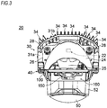
- a vehicle headlamp 10 is configured so that a projection type light source unit 20 including a light emitting element (e.g.. a high luminous flux corresponding LED) 22 as a light source is accommodated in a lamp chamber defined by a container-like lamp body 12 opened on the front side and a plain front cover (translucent cover) 14 attached to the front opening.
- a light emitting element e.g.. a high luminous flux corresponding LED
- the light source unit 20 includes a heat sink 30 which is made of aluminum die cast and in which a large number of heat-dissipation fins 34 extend from a base plate 31 having an L-shaped longitudinal section.
- the light emitting element 22 as a light source and a resin reflector 24 for reflecting light emitted from the light emitting element 22 forward are attached on an upper surface of a horizontal base plate 31a of the base plate 31
- a pedestal 32 adapted for mounting a light emitting element and having an element mounting surface 32a parallel to upper and lower surfaces of the horizontal base plate 31a is provided at the center of the upper surface of the horizontal base plate 31a constituting the heat sink 30.
- the light emitting element 22 is attached to the pedestal 32 with its irradiation axis directed upward.
- the reflector 24 attached to the rear of the upper surface of the horizontal base plate 31a is disposed to cover the upper side of the light emitting element 22.
- An effective reflecting surface 24a for the travelling beam is formed substantially on the lower half of the front surface of the reflector 24, and an effective reflecting surface 24b for the low beam is formed substantially on the upper half thereof.
- a sub reflector 25 extending obliquely forward and downward is formed integrally on a front edge portion of the reflector 24.
- the reflector 24 is fixed to the horizontal base plate 31a by fastening screws 28 (see FIGS. 3 and 4 ) vertically penetrating screw insertion holes 27 provided in flange portions 26 of the reflector 24.
- a vertical base plate 31b of the base plate 31 constituting the heat sink 30 is formed in a roughly R shape (see FIG. 3 ) in a plan view with the pedestal 32 as the center.
- the heat-dissipation fins 34 formed to extend rearward at equal intervals in the right and left direction extend in the upper and lower direction.
- the heat-dissipation fins 34 provided in the heat sink 30 extend from the back surface side of the vertical base plate 31b to the lower side of the horizontal base plate 31a and further to the front lower side of the horizontal base plate 31a. In this way, a large heat-dissipation area is secured and the heat-dissipation performance of the heat sink 30 is improved.
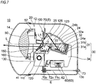
- a projection lens 50 made of resin is disposed in front of the heat sink 30, and a light distribution switching shade mechanism 40 including a movable shade 120 is disposed between the reflector 24 and the projection lens 50, thereby forming the integral light source unit 20.
- a lens holder 52 for holding the projection lens 50 and a support plate 100 constituting the light distribution switching shade mechanism 40 and having a rectangular shape in a front view are fastened together and fixed by two fastening screws 54a (see FIGS. 1 and 4 ), and the projection lens 50 is disposed on an optical axis L of the light source unit 20.
- a reference numeral 54b in FIGS. 1 and 4 refers to a fastening screw for fixing (the support plate 100 of) the light distribution switching shade mechanism 40 to the heat sink 30.
- a lighting circuit unit 60 for controlling the lighting of the light emitting element 22 is fixed to the lower surface side of the heat sink 30 by two screws 66.
- a lighting circuit 62 is configured by a circuit board on which electronic components (circuit elements) are mounted. The lighting circuit 62 is accommodated in a lighting circuit housing 63 and integrated as the lighting circuit unit 60 (see FIG. 2 ).
- the movable shade 120 is pivoted (swung in the front and rear direction) around a pivot shaft 110 fixed to the support plate 100 by the driving of an electromagnetic solenoid 130 constituting the light distribution switching shade mechanism 40.
- an electromagnetic solenoid 130 constituting the light distribution switching shade mechanism 40.
- the light distribution formed by the light source unit 20 is switched between a low beam (see FIG. 8A ) with excellent visibility at a short distance and a travelling beam (see FIG. 8B ) with excellent visibility at a long distance.
- the light distribution switching shade mechanism 40 includes the support plate 100 having a rectangular frame shape, the pivot shaft 110 fixed to the front surface side of the support plate 100 and extending in the right and left direction, the movable shade 120 pivotably assembled to the pivot shaft 110, a torsion coil spring 112 interposed between the support plate 100 and the movable shade 120, the electromagnetic solenoid 130 fixed to the support plate 100 and serving as an actuator for driving the movable shade, a link member 140 interposed between the movable shade 120 and the electromagnetic solenoid 130 and serving as a power transmission means for converting the advancing and retracting motion of an output shaft 133 of the electromagnetic solenoid 130 into the pivot motion of the movable shade 120 and transmitting the converted power, a movable reflector 150 integrated with the movable shade 120, and a sub shade 160 fixed to the support plate 100 and disposed at a predetermined position in front of the movable reflector 150 (see FIGS. 4 and
- the movable shade 120 is configured by a frame body 121 having a substantially rectangular shape in a plan view and opened on the front side.
- side walls 121b (a left side wall 121b1 and a right side wall 121b2) extend forward from both end portions of a back surface wall 121a of the movable shade 120 extending to the right and left.
- Front end portions of the side walls 121b (the left side wall 121b1 and the right side wall 121b2) are bent inward in a width direction to form a pair of right and left rectangular reflector mounting portions 121c, 121c.
- the movable reflector 150 (see FIG. 5 ) is fixed to the reflector mounting portion 121c, so that the structural strength of the movable shade 120 is secured.
- a shade body 123 for forming a clear cutoff line is provided on an upper edge portion of the back surface wall 121a.
- the shade body 123 is configured by a front extending portion 123a and a rear extending portion 123b.
- an extending portion 121a1 extending vertically downward in a band shape from a lower edge portion of the back surface wall 121a extending to the right and left is folded upward so as to be in close contact with the rear surface of the back surface wall 121a, and a leading end of the folded extending portion 121a1 is formed in a substantially triangular shape, thereby forming the rear extending portion 123b.
- the rear extending portion 123b may be simply formed by cutting and raising a part of the back surface wall 121a (a region in the vicinity of the upper edge portion of the back surface wall 121a) upward in a triangular shape.
- a measure e.g., a measure for plugging the opening portion with a separate member
- a triangular opening portion an opening portion corresponding to an outer shape of the movable shade body 123 appearing on the back surface wall 121a.
- such opening portion is formed in the back surface wall 121a, and thus, light leakage prevent measure is unnecessary. Accordingly, the structure of the movable shade 120 (the frame body 121) is simplified.
- a flat plate portion 121d extending horizontally forward is formed on the front surface side on the right side of the back surface wall 121a.
- a hole 121d1 for locking one end of the torsion coil spring 112 interposed between the support plate 100 and the movable shade 120 is provided in the flat plate portion 121d.
- circular holes 124 for inserting the pivot shaft 110 are provided to face each other on the front side of the side walls 121b (the left side wall 121b1 and the right side wall 121b2).
- a regulating projection 125 protruding outward (laterally) is provided at the upper portions of the side walls 121b (the left side wall 121b1 and the right side wall 121b2), respectively.
- a second regulating projection 126 protruding inward is provided at the lower end portion of the right side wall 121b2 close to the rear side.
- the regulating projections 125 on the upper side are locking members for abutting against a rear surface of the support plate 100 and positioning the movable shade 120 in the first mode
- the second regulating projection 126 on the lower side is a locking member for abutting against a back surface of the support plate 100 and positioning the movable shade 120 in the second mode.
- a tongue-like protrusion 127 formed in a substantially L-shaped longitudinal section and extending downward from the rear side is provided at a position below the circular hole 124 inside the left side wall 121b1.
- the protrusion 127 is a member for cooperating with the link member 140 (to be described later) and converting the advancing and retracting motion of the output shaft 133 of the electromagnetic solenoid 130 into the pivot motion of the movable shade 120.
- a light transmitting hole 100a and an arrangement hole 100b are formed to be spaced apart from each other in the upper and lower direction by a horizontal frame portion 102 which has a predetermined width and in which a mounting surface portion 103 protruding forward in an arc shape is provided.
- a circular hole 103a is provided in the arc-shaped mounting surface portion 103.
- a support shaft 146 for supporting the link member 140 (to be described later) is inserted through the circular hole 103a from above and protrudes below the mounting surface portion 103.
- a rectangular upright wall 101a is provided on the right and left side edge portions of the light transmitting hole 100a close to the horizontal frame portion 102 of the support plate 100, respectively.
- movable shade pressing pieces 104 protruding rearward are provided to be spaced apart from each other in the right and left direction.
- An L-shaped shaft mounting piece 106 protruding forward is provided at the position of the upright walls 101a outside the movable shade pressing pieces 104, respectively.
- the pivot shaft 110 is inserted into the circular holes 124 provided in the side walls 121b of the movable shade 120. Both right and left end portions of the pivot shaft 110 are inserted into the shaft mounting pieces 106 of the support plate 100 from above. The shaft mounting pieces 106 are bent and crimped. In this way, the pivot shaft 110 is fixed to the front surface side of the support plate 100.
- the movable shade 120 is inserted through the light transmitting hole 100a and disposed such that the movable shade body 123 is located on the rear side of the support plate 100, and the movable reflector 150 and the protrusion 127 are located on the front side of the support plate 100.
- the right and left side walls 121b of the movable shade 120 are held in a state of being in contact with the pair of right and left movable shade pressing pieces 104 on the side of the support plate 100, so that the movement in the right and left direction of the movable shade 120 with respect to the support plate 100 is regulated.
- the movable shade 120 is pivotable with respect to the support plate 100 with the pivot shaft 110 as a pivot point.
- the movable shade 120 is pivoted between the first mode (see FIG. 2 ) in which the movable shade 120 is erected and the second mode (see FIG. 7 ) in which the movable shade 120 is tilted rearward (hereinafter, referred to as rearward tilting).
- the regulating projections 125 on the side of the movable shade 120 are held in a state of being urged and abutted against the rear surface of the upright wall 101a of the support plate 100. Therefore, the headlamp (the light source unit 20) forms a low-beam light distribution.
- the regulating projections 125 on the side of the movable shade 120 are spaced rearward from the support plate 100, and the second regulating projection 126 on the side of the movable shade 120 is held in a state of being urged and abutted against the rear surface of an upright wall 101b of the support plate 100. Therefore, the headlamp (the light source unit 20) forms a travelling-beam light distribution.
- the torsion coil spring 112 is arranged externally fitted to the pivot shaft 110.
- One end of the spring 112 is engaged with (the hole 121d1 of the flat plate portion 121d of) the movable shade 12, and the other end thereof is engaged with the rear surface of the upright wall 101b of the support plate 100. Therefore, the torsion coil spring 112 interposed between the support plate 100 and the movable shade 120 causes the movable shade 120 to be urged in a direction pivoted from the second mode in which the movable shade body 123 is tilted rearward toward the first mode in which the movable shade body 123 is erected.
- the urging force of the spring 112 causes the movable shade 120 to be held in the first mode in which the regulating projections 125 are pressed against the rear surface of the upright wall 101a of the support plate 100.
- the second regulating projection 126 is pressed against the rear surface of the upright wall 101b of the support plate 100 against the urging force of the spring 112, and the movable shade 120 is held in the second mode.
- the link member 140 has a base portion 141 and a flat plate-like sliding engagement portion 142 protruding laterally from the base portion 141.
- a connecting shaft portion 143 protruding downward is provided on the front end portion of the base portion 141, and a supported hole 141a penetrating in the upper and lower direction is formed in the rear end portion of the base portion 141.
- the support shaft 146 protruding from the lower surface of the mounting surface portion 103 of the support plate 100 is inserted into the supported hole 141a of the link member 140, and a retaining ring 148 is attached to a lower end portion of the support shaft 146.
- the link member 140 is pivotably supported on the support plate 100 with the support shaft 146 as a pivot point.
- a part of the link member 140 is inserted through the arrangement hole 100b of the support plate 100, and the sliding engagement portion 142 is in contact with the rear surface side of the protrusion 127 of the movable shade 120.
- the electromagnetic solenoid 130 functions as an actuator for pivoting the movable shade 120.
- the electromagnetic solenoid 130 includes a laterally elongated yoke case 131 formed in a frame shape and penetrating in the front and rear direction, a coil body 132 disposed inside the yoke case 131, and the output shaft 133 movable in the right and left direction.
- the axial direction of the coil body 132 is the right and left direction.
- Drive current is supplied to the coil body 132 from a power supply circuit 134 provided adjacent to the lower side of the yoke case 131.
- the axial direction of the output shaft 133 coincides with the right and left direction. A part of the output shaft 133 protrudes laterally from the yoke case 131. An annular connection groove 133a for engaging with the connecting shaft portion 143 of the link member 140 is formed at a portion near the leading end of the output shaft 133.
- the output shaft 133 moves in the axial direction according to the supply state of the drive current to the coil body 132.
- the yoke case 131 is provided with brackets 131a respectively extending upward and downward. Positioning holes 131b are provided in the brackets 131a. Meanwhile, only the bracket 131a on the upper side is shown in FIG. 5 .
- positioning protrusions 108 engageable with the positioning holes 131b on the side of the yoke case 131 are provided. Further, the positioning holes 131b of the brackets 131a are engaged with the positioning protrusions 108, and the brackets 131a are fixed to the front surface of the support plate 100 by screwing or the like. In this manner, the electromagnetic solenoid 130 is disposed in the arrangement hole 100b.
- the connecting shaft portion 143 of the link member 140 is connected to the electromagnetic solenoid 130 by being inserted into the connection groove 133a of the output shaft 133. Therefore, when the output shaft 133 moves in the axial direction according to the supply state of the drive current to the coil body 132, the link member 140 is pivoted with the support shaft 146 as a pivot point. Depending on the contact position of the protrusion 127 on the side of the movable shade 120 with the sliding engagement portion 142 of the link member 140, the movable shade 120 is pivoted in a direction tilted rearward with the pivot shaft 110 as a pivot point.
- the sub shade 160 is attached to the front surface side of the support plate 100 by screwing or the like so as to cover the electromagnetic solenoid 130.
- the sub shade 160 is formed by cutting and raising a metal plate such as a steel plate or an aluminum plate into a predetermined shape.
- the sub shade 160 is disposed in an upright wall shape between the projection lens 50 and the shade mechanism 40 in order not only to hide the coil body 132 of the electromagnetic solenoid 130, but also to prevent the light leakage from the front cover 14 or melt damage of resin products by sunlight incident through the projection lens 50.
- the spring force (urging force) of the torsion coil spring 112 causes the movable shade 120 to be held in the first mode in which the regulating projections 125 are pressed against the rear surface of (the upright wall 101a of) the support plate 100 (see FIG. 2 ).
- the output shaft 133 of the electromagnetic solenoid 130 is positioned at a movement end in a direction protruding from the yoke case 131.
- the link member 140 is positioned in a first pivot end at which the sliding engagement portion 142 is located on the rear side.
- the protrusion 127 of the movable shade 120 is in contact with a front surface side 142a (see FIG. 5 ) of the sliding engagement portion 142.
- the movable shade 120 In the first mode in which the movable shade 120 is erected, light emitted from the light emitting element 22 is reflected by the reflector 24 and directed to the projection lens 50. However, a part of the light is shielded by the movable shade 120, and the light which is not shielded is incident on the projection lens50 and projected by the projection lens 50.
- the movable shade body 123 In the first mode in which the movable shade 120 is erected, the movable shade body 123 is located at the position of a rear focus F of the projection lens 50, and a low-beam light distribution suitable for short distance irradiation is formed by the light source unit 20. That is, as shown in FIG. 8A , a low-beam light distribution having a predetermined cutoff line CL corresponding to the movable shade body 123 is formed.
- a predetermined low-beam light distribution (see FIG. 8A ) based on the reflected light of the reflector 24 and having the cutoff line CL corresponding to the movable shade body 123 is formed through the projection lens 50.
- the movable reflector 150 integrated with the movable shade 120 is outside an optical path of a reflected light L1 by the sub reflector 25, and the reflected light by the sub reflector 25 is not guided to the projection lens 50 via the movable reflector 150. Therefore, the reflected light L1 by the sub reflector 25 does not affect the low-beam light distribution.
- the output shaft 133 moves in a direction drawn into the yoke case 131, and the link member 140 is pivoted with the support shaft 146 as a pivot point.
- the link member 140 is pivoted, the sliding engagement portion 142 of the link member 140 pushes the rear surface of the protrusion 127 of the movable shade 120 forward. Therefore, against the urging force of the torsion coil spring 112, the movable shade 120 is pivoted in a direction tilted rearward with the pivot shaft 110 as a pivot point (see FIG. 7 ).
- the movable shade body 123 moves obliquely downward and rearward. Therefore, the light reflected by the reflector 24 is incident on the projection lens 50 without being shielded by the movable shade body 123. In this manner, a travelling beam suitable for long distance irradiation is formed.
- a first travelling-beam light distribution Pa (see FIG. 8B ) based on the reflected light of the reflector 24 and having no cutoff line corresponding to the movable shade body 123 is formed through the projection lens 50.
- the movable reflector 150 is erected in association with the rearward tilting of the movable shade 120, protrudes on the optical path of the reflected light L1 by the sub reflector 25, and reflects the reflected light L1 toward the projection lens 50. Therefore, a second travelling-beam light distribution Pb (see FIG. 8B ) based on the reflected light L1 of the sub reflector 25 and irradiating, for example, the vicinity of the optical axis L is formed through the projection lens 50.
- the first travelling-beam light distribution Pa based on the reflected light L1 of the reflector 24 and the second travelling-beam light distribution Pb based on the reflected light of the sub reflector 25 are combined, so that a predetermined travelling-beam light distribution with, for example, high central luminosity is formed.
- the spring force (urging force) of the torsion coil spring 112 causes the movable shade 120 to be pivoted from the second mode to the first mode with the pivot shaft 110 as a pivot point.
- the link member 140 is pivoted, and the output shaft 133 of the electromagnetic solenoid 130 moves to a movement end in a direction protruding from the yoke case 131.
- the second travelling-beam light distribution Pb based on the reflected light L1 of the sub reflector 25 is formed through the projection lens 50. Therefore, the sub reflector 25 is positioned in a range of an outer shape of the projection lens 50 and does not protrude greatly outward form the projection lens 50, unlike the conventional paraboloid-shaped sub reflector (see Patent Document 1). In this manner, in the present embodiment, the light source unit 20 can be made compact, and accordingly, the headlamp 10 can be miniaturized, compared with Patent Document 1.
- the light source unit 20 accommodated in the lamp chamber is supported at three points including a pair of aiming points A, B spaced apart in the right and left direction on the upper side of the lamp chamber and one aiming point C located almost directly below the aiming point B. Further, with an aiming mechanism E, the light source unit 20 is supported tiltably around a horizontal tilting axis Lx passing through the aiming points A, B and a vertical tilting axis Ly passing through the aiming points B, C, respectively.
- three aiming screws 71a, 71b, 71c provided with pivotal operation portions 73 are rotatably supported in through-holes 13a, 13b, 13c (through-holes 13a, 13b are not shown) provided in the back surface wall of the lamp body 12 and corresponding to the aiming points A, B, C and extend into the lamp chamber.
- Bearing nuts 72a, 72b, 72c respectively screwed to leading ends of the aiming screws 71a, 71b, 71c are mounted in the holes 70a, 70b, 70c of the bracket 70. That is, the optical axis L of the light source unit 20 can be tiltably adjusted in the right and left direction (the upper and lower direction) by pivoting the aiming screw 71a (71c) constituting the aiming mechanism E. Meanwhile, the aiming bracket 70 is not shown in FIG. 3 .
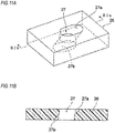
- the sub reflector 25 extending obliquely forward and downward is formed integrally with the front edge portion of the reflector 24, portions 27a, 27b of the upper and lower opening side inner peripheral surfaces of the screw insertion holes 27 provided in the flange portions 26 (see FIGS. 3 , 4 and 11 ) of the reflector 24 are formed in a tapered shape inclined in the same direction as the demolding direction (direction indicated by the outline arrow in FIGS. 9 and 10 ) of the reflector 24. Therefore, without using split molds, the reflector 24 and the sub reflector 25 are integrally molded so that the screw insertion holes 27 of the flange portions 26 are not undercut.
- an effective reflecting surface (an effective reflecting surface 24a capable of forming a light distribution upward from the optical axis of the projection lens 50, see FIGS. 2 and 9 ) corresponding to a travelling beam is formed on the lower side of the reflector 24.
- the sub reflector 25 is formed to extend obliquely forward and downward. Therefore, when molding the sub reflector 25 integrally with the reflector 24, the effective reflecting surface 24a on the lower side of the reflector 24 is undercut when a molded product (see FIG. 9 ) is demolded in the upper and lower direction. On the other hand, the sub reflector 25 is undercut when a molded product is demolded in the front and rear direction.
- the sub reflector 25 and the reflector 24 can be integrally molded.
- the screw insertion holes 27 for inserting the fastening screws 28 therethrough and fixing the reflector 24 on the base plate 31 of the heat sink 30 are provide in the flange portions 26 of the reflector 24. It is also necessary to mold these screw insertion holes 27 integrally with the reflector 24.
- the screw insertion holes 27 are undercut.
- the portions 27a, 27b of the upper and lower opening side inner peripheral surfaces of the screw insertion holes 27 in the flange portions 26 of the reflector 24 are formed in a tapered shape inclined in the same direction as the demolding direction of the reflector 24. Therefore, when demolding the reflector 24 formed integrally with the sub reflector 25, the screw insertion holes 27 are not undercut.
- FIGS. 9 , 10 and 12 showing a reflector molding die 200 (an upper die 210 and a lower die 220).
- Recessed portions 212, 222 cooperating with each other to form a cavity c for molding the flange portions 26 of the reflector 24 are provided on division surfaces 211, 221 of the reflector molding die 200 (the upper die 210 and the lower die 220).
- the recessed portions 212, 222 face each other.
- cylindrical protrusions 214, 224 cooperating with each other to form an inner peripheral surface of the screw insertion hole 27 are provided to face each other.
- Outer surfaces 214a, 224a on a mold release direction (demolding direction) side in the pair of cylindrical protrusions 214, 224 facing each other are formed in a tapered shape inclined along the mold release direction (demolding direction). Therefore, when integrally molding the sub reflector 25 and the reflector 24, the screw insertion holes 27 provided in the flange portions 26 of the reflector 24 are not undercut.
- FIGS. 13 to 17 show a vehicle headlamp 10A according to a second embodiment of the disclosure.
- FIGS. 17A, 17B and 17C are views for explaining an operation of a light distribution switching shade mechanism.
- a movable reflector is shown as being transparent.
- three points that is, the structure of a light distribution switching shade mechanism 40A, the shape and attachment position of a sub shade 160A, and the support structure of a light source unit 20A in a lamp chamber are largely different from those of the first embodiment. Since other configurations are the same as those of the first embodiment, the same components as those of the first embodiment are denoted by the same reference numerals, and duplicate explanations thereof are omitted.
- the pivot shaft 110 is fixed to the support plate 100
- the movable reflector 150 is fixed to the movable shade 120 pivotable around the pivot shaft 110
- the movable shade 120 and the movable reflector 150 are always integrally pivoted with respect to the support plate 100.
- the pivot shaft 110 is fixed to a support plate 100A (see FIG. 15 ) opened on the upper side, and a movable shade 120A and a movable reflector 150A are provided to be pivotable around the pivot shaft 110, respectively.
- a second torsion coil spring 112A is interposed between the movable shade 120A and the movable reflector 150A. The movable shade 120A and the movable reflector 150A are urged and held in a direction (in a direction approaching each other above the pivot shaft 110) in which they are erected together.
- the movable shade 120A when the movable shade 120A is shifted from the first mode in which it is erected to the second mode in which it is tilted rearward by the driving of the electromagnetic solenoid 130, the movable shade 120A and the movable reflector 150A are held at a predetermined angle and pivoted integrally around the pivot shaft 110 fixed to the support plate 100A.
- regulating projections 154 are locked to the front surface of the support plate 100A serving as a locking part, and the movable reflector 150A is held in an erected form protruding on the optical path of the reflected light L1 by the sub reflector 25.
- the movable shade 120A is further pivoted to a predetermined tilting position in which the second regulating projection 126 is locked to the rear surface of the support plate 100A serving as a second locking part.
- the movable shade 120A is formed in the same rectangular shape as the movable shade 120 of the first embodiment, but the rectangular reflector mounting portions 121c, 121c (see FIG. 6 ) for fixing the movable reflector 150A are not provided on the front surface portions of the right and left side walls 121b (the left side wall 121b1 and the right side wall 121b2).
- each of the right and left side walls 121b of the movable shade 120A has a front edge portion formed in a circular arc shape, and peripheral regions of the circular holes 124 through which the pivot shaft 110 is inserted are configured by circular bending stepped portions 124a bulging outward. Therefore, the rigidity strength of the side walls 121b is increased, and the contact area of the side walls 121b and the movable shade pressing pieces 104 on the side of the support plate 100A is reduced. In this way, the smooth pivoting of the movable shade 120A with respect to the support plate 100A is secured.
- stepped portions 121b3 for locking the movable reflector 150A pivotably assembled to the pivot shaft 110 are provided on the front edge portions of the right and left side walls 121b.
- the movable reflector 150A is formed in a rectangular flat plate shape elongated in the right and left direction, and tongue-like extending portions 152 extending rearward are formed on both right and left end portions of the movable reflector 150A.
- Circular holes 152a through which the pivot shaft 110 can be inserted are provided in the extending portions 152.
- the extending portions 152 are arranged to contact with the inner side of the right and left side walls 121b of the movable shade 120A, and the movable shade 120A and the movable reflector 150A can be relatively pivoted around the pivot shaft 110.
- the regulating projections 154 protruding outward (laterally) are provided on the extending portions 152 of the movable reflector 150A.
- the regulating projections 154 are provided at positions in which they can engage with the stepped portions 121b3 (see FIG. 16 ) on the front end portions of the side walls 121b of the movable shade 120A.
- the torsion coil spring 112A is interposed between the movable shade 120A and the movable reflector 150A, and the movable reflector 150A is urged to rotate in such a direction that the regulating projections 154 abut against the stepped portions 121b3 on the front end portions of the side walls 121b.
- the torsion coil spring 112A is externally fitted to the pivot shaft 110.
- One end of the spring 112A is engaged with a predetermined position of the left side wall 121b1 of the movable shade 120A, and the other end thereof is engaged with a predetermined position of the movable reflector 150A.
- the movable shade 120A and the movable reflector 150A are integrated into a state where the regulating projections 154 are urged and abutted against the stepped portions 121b3 on the front end portions of the side walls 121b by the torsion coil spring 112A interposed between the movable shade 120A and the movable reflector 150A.
- the movable shade 120A integrated with the movable reflector 150A so that the regulating projections 154 are urged and abutted against the stepped portions 121b3 on the front end portions of the side walls 121b is pivoted around the pivot shaft 110 by the driving of the electromagnetic solenoid 130 (the energization to the coil body 132) and shifted from the first mode (shown in FIGS. 15 , 16 , 17A and 13A ) in which the movable shade 120A is erected and to the second mode (shown in FIGS. 17C and 13B ) in which the movable shade 120A is tilted rearward.
- the electromagnetic solenoid 130 the energization to the coil body 132
- the regulating projections 154 are locked to a front surface 100A1 of the support plate 100A and the movable reflector 150A is held in an erected form protruding on the optical path of the reflected light L1 by the sub reflector 25 (see FIG. 13B ), whereas the movable shade 120A continues to pivot against the urging force of the spring 112A and is further pivoted to a predetermined tilting position (from the position indicated by the imaginary line to the position indicated by the solid line in FIG. 13B ) in which the second regulating projection 126 provided on the movable shade 120A abuts against the rear surface of the support plate 100A serving as the second locking part (see FIG. 17C ).
- the movable reflector 150A is held in a state where the regulating projections 154 abut against the front surface of the support plate 100A by the urging force of the second spring 112A interposed between the movable shade 120A and the movable reflector 150A.
- the movable shade 120A continues to pivot against the urging force of the spring 112 interposed between the support plate 100A and the movable shade 120A and the urging force of the spring 112A interposed between the movable reflector 150A and the movable shade 120A and is held in a state where the second regulating projection 126 provided on the movable shade 120A abuts against the back surface of the support plate 100A serving as the second locking part.
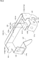
- the box-shaped sub shade 160 formed by cutting and raising a metal plate into a predetermined shape is attached to the front surface side of the support plate 100 of the light distribution switching shade mechanism 40 by screwing or the like.
- the sub shade 160A of a simple shape molded by cutting and raising a metal plate into a predetermined shape has a structure in which bracket parts 162 on both ends thereof are engaged with engagement recessed portions 53 on the side of a resin lens holder 52A, and protruding portions 53a on the side of the engagement recessed portions 53 protruding from circular holes (not shown) provided in the bracket parts 162 are fixed by thermal caulking.
- the sub shade 160 of the first embodiment is formed in a box shape having a width corresponding to the lateral width of the support plate 100 of the light distribution switching shade mechanism 40.
- the sub shade 160A of the present embodiment is configured in a compact and simple shape having a width corresponding to the lateral width of the lens holder 52A.
- the metallic sub shade 160A may be integrated with the resin lens holder 52A by insert molding.
- the metallic sub shade 160A may be fixed and integrated to the lens holder 52A by welding or caulking.
- the sub shade 160A having a compact and simple shape can be easily integrated with the lens holder 52. Therefore, the attachment of the sub shade 160A is facilitated, and the size of the light source unit 20 is reduced, which leads to the size reduction of the headlamp.
- the light source unit 20A will be described.
- the light source unit 20 is supported by the aiming mechanism E and (the optical axis L of) the light source unit 20 can be tiltably adjusted in the upper and lower direction and in the right and left direction.
- the light source unit 20A is supported by a swiveling mechanism (not shown) in a lamp chamber and (the optical axis L of) the light source unit 20A can be pivotally adjusted in the horizontal direction (the right and left direction) following a travelling direction of a vehicle (handle steering).
- the light source unit 20A may be supported to be tiltable in the upper and lower direction with respect to the lamp body 12.
- a leveling adjustment mechanism (not shown) is coupled to the lamp body 12.
- the optical axis of) the light source unit 20A may be tilted in the upper and lower direction and the direction of the optical axis of the light source unit 20A may be adjusted in the upper and lower direction according to the weight of an on-board article (may be adjusted so that the inclination in the upper and lower of the optical axis with respect to the road surface is always constant).
- the movable shade 120A when the movable shade 120A is shifted from the first mode to the second mode by the driving of the electromagnetic solenoid 130, the movable shade 120A is pivoted to a predetermined position in which the second regulating projection 126 provided on the movable shade 120A is locked to the rear surface of the support plate 100 against the urging force of the torsion coil spring 112A.
- the second regulating projection 126 is not provided on the movable shade 120A.
- the movable shade 120A when the movable shade 120A is shifted from the first mode to the second mode by the driving of the electromagnetic solenoid 130, the movable shade 120A is pivoted to a predetermined position corresponding to the maximum driving position of the electromagnetic solenoid 130 serving as an actuator against the urging force of the torsion coil spring 112A.
- the second mode (mode in which the movable shade 120A is tilted rearward and the movable reflector 150A is erected) corresponding the travelling beam in the second embodiment described above is a state in which the movable shade 120 is urged to rotate in a direction of being titled rearward by the driving force of the electromagnetic solenoid 130. That is, the driving force of the electromagnetic solenoid 130 acts as a compressed force on the contact portion between the second regulating projection 126 on the side of the movable shade 120A and the rear surface of the support plate 100A.
- the second regulating projection 126 on the side of the movable shade 120A abuts against the rear surface of the support plate 100A, and the movable shade 120A is positioned to the second mode (mode in which the movable shade 120A is tilted and the movable reflector 150A is erected) corresponding to the travelling beam.
- the second regulating projection 126 on the side of the movable shade 120A and the rear surface of the support plate 100A are held in a contact state pressed by the driving force of the electromagnetic solenoid 130.
- the output shaft 133 of the electromagnetic solenoid 130 is in a state of being stopped at the middle of its operation range. This also applies to the first embodiment.
- the load on the driving part of the electromagnetic solenoid 130 is large, and there is a possibility that the electromagnetic solenoid 130 may fail or the durability thereof may be lowered.
- the compressive force (the driving force of the electromagnetic solenoid 130) acting on the contact portion between the second regulating projection 126 on the side of the movable shade 120A and the rear surface of the support plate 100A so as to reliably hold the second mode.
- the power consumption of the electromagnetic solenoid 130 increases accordingly.
- the movable shade 120A and the movable reflector 150A are pivoted integrally around the pivot shaft 110.
- the regulating projections 154 provided on the movable reflector 150A are locked to the front surface of the support plate 100A, and the movable reflector 150A is held in an erected form protruding on the optical path of the reflected light L1 by the sub reflector 25.
- the movable shade 120A is further pivoted to a predetermined position corresponding to the maximum driving position of the electromagnetic solenoid 130.
- the output shaft 133 of the electromagnetic solenoid 130 serving as an actuator is not stopped at an intermediate state of its operating range, but is stopped at the maximum driving position of its operating range. Specifically, the output shaft 133 is stopped in a state of being in contact with a stopper inside the electromagnetic solenoid 130.
- the positioning accuracy of the tilted movable shade 120A in the second mode is somewhat lower than that of the movable shades 120, 120A in the first and second embodiments.
- the movable shade 120A is tilted to a position where the reflected light of the reflector 24 is not shielded. Therefore, even when the positioning accuracy of the movable shade 120A is somewhat reduced, it does not affect the formation of a first travelling-beam light distribution P1.
- the movable reflector 150A is held in an erected form in which the regulating projections 154 of the movable reflector 150A are urged and abutted against the front surface of the support plate 100 by the spring 112A interposed between the movable shade 120A and the movable reflector 150A. Therefore, the positioning accuracy of the movable reflector 150A is high and does not affect the formation of a second travelling-beam light distribution P2 based on the reflected light of the sub reflector 25.
- both the spring members interposed between the support plates 100, 100A and the movable shades 120, 120A and the spring member interposed between the movable shade 120A and the movable reflector 150A are the torsion coil springs 112, 112A.
- the spring members may be spring members such as leaf springs.
- the actuator for pivoting the movable shade is configured by an electromagnetic solenoid.
- the actuator may be a driving source such as a motor.
- the link member is provided between the electromagnetic solenoid and the movable shade in order to convert the linear motion of the output shaft of the electromagnetic solenoid to the rotational motion of the movable shade.
- other mechanisms such as a rack and pinion may be used.
Landscapes
- Engineering & Computer Science (AREA)
- General Engineering & Computer Science (AREA)
- Non-Portable Lighting Devices Or Systems Thereof (AREA)
Applications Claiming Priority (2)
| Application Number | Priority Date | Filing Date | Title |
|---|---|---|---|
| JP2016184100A JP6774281B2 (ja) | 2016-09-21 | 2016-09-21 | 車両用前照灯 |
| PCT/JP2017/033535 WO2018056218A1 (ja) | 2016-09-21 | 2017-09-15 | 車両用前照灯 |
Publications (2)
| Publication Number | Publication Date |
|---|---|
| EP3517832A1 true EP3517832A1 (de) | 2019-07-31 |
| EP3517832A4 EP3517832A4 (de) | 2020-06-17 |
Family
ID=61689471
Family Applications (1)
| Application Number | Title | Priority Date | Filing Date |
|---|---|---|---|
| EP17852991.3A Withdrawn EP3517832A4 (de) | 2016-09-21 | 2017-09-15 | Frontscheinwerfer für fahrzeug |
Country Status (5)
| Country | Link |
|---|---|
| US (1) | US11092308B2 (de) |
| EP (1) | EP3517832A4 (de) |
| JP (1) | JP6774281B2 (de) |
| CN (1) | CN109690177B (de) |
| WO (1) | WO2018056218A1 (de) |
Families Citing this family (11)
| Publication number | Priority date | Publication date | Assignee | Title |
|---|---|---|---|---|
| JP6770347B2 (ja) * | 2016-06-27 | 2020-10-14 | 株式会社小糸製作所 | 車両用前照灯 |
| JPWO2019230663A1 (ja) * | 2018-05-31 | 2021-06-24 | 株式会社小糸製作所 | 光源ユニット |
| CN111911883B (zh) * | 2019-05-07 | 2023-03-17 | 株式会社小糸制作所 | 供电附件以及灯具单元 |
| JP7481364B2 (ja) | 2019-12-27 | 2024-05-10 | 株式会社小糸製作所 | 車輌用前照灯 |
| JP7528571B2 (ja) | 2020-06-30 | 2024-08-06 | 市光工業株式会社 | 車両用灯具 |
| JP7537159B2 (ja) | 2020-07-30 | 2024-08-21 | 市光工業株式会社 | 車両用灯具 |
| CN114353014B (zh) * | 2022-01-14 | 2024-02-09 | 浙江友德电子科技有限公司 | 一种方便调节的远近光一体式车灯 |
| CN119836543A (zh) * | 2022-08-03 | 2025-04-15 | 亮锐有限责任公司 | 头灯组件和组装的方法 |
| US12092284B2 (en) * | 2022-12-29 | 2024-09-17 | Sonar Auto Parts Co., Ltd. | Vehicle lamp having switching structure for low-beam and high-beam headlights |
| US12163637B2 (en) * | 2023-05-11 | 2024-12-10 | Valeo Vision | Headlamp for a vehicle |
| JP2025143636A (ja) * | 2024-03-19 | 2025-10-02 | 株式会社小糸製作所 | 車両用灯具 |
Family Cites Families (32)
| Publication number | Priority date | Publication date | Assignee | Title |
|---|---|---|---|---|
| JPS60164478U (ja) * | 1984-04-11 | 1985-10-31 | スタンレー電気株式会社 | 二輪車用方向指示灯用支持装置 |
| CN2034924U (zh) * | 1988-03-23 | 1989-03-29 | 杨庆询 | 汽车安全行驶照明灯 |
| DE19933657A1 (de) * | 1999-07-17 | 2001-01-18 | Bosch Gmbh Robert | Scheinwerfer für Fahrzeuge |
| US6315439B1 (en) * | 1999-09-21 | 2001-11-13 | Elco Textron Inc. | Headlamp adjustor and method |
| DE60123370T2 (de) * | 2000-12-25 | 2007-08-23 | Stanley Electric Co. Ltd. | Fahrzeugscheinwerfer mit einer verstellbaren Blende und einer verstellbaren Reflektorfläche zur Erzeugung eines Abblend- und Fernlichtbündels |
| CN2504748Y (zh) * | 2001-06-07 | 2002-08-07 | 光阳工业股份有限公司 | 摩托车方向灯切换开关 |
| JP4365755B2 (ja) | 2004-09-01 | 2009-11-18 | 株式会社小糸製作所 | 車両用前照灯 |
| AT500893B1 (de) * | 2004-10-14 | 2006-11-15 | Zizala Lichtsysteme Gmbh | Fahrzeugscheinwerfer |
| JP4341538B2 (ja) * | 2004-12-06 | 2009-10-07 | 市光工業株式会社 | ヘッドランプ |
| JP2006221882A (ja) * | 2005-02-08 | 2006-08-24 | Koito Mfg Co Ltd | 車両用前照灯 |
| JP4497056B2 (ja) * | 2005-08-19 | 2010-07-07 | 市光工業株式会社 | 車両用前照灯 |
| JP4527639B2 (ja) * | 2005-09-09 | 2010-08-18 | 株式会社小糸製作所 | 車両用前照灯 |
| JP4597890B2 (ja) * | 2006-03-29 | 2010-12-15 | 株式会社小糸製作所 | 車両用前照灯の灯具ユニット |
| JP2007317385A (ja) * | 2006-05-23 | 2007-12-06 | Ichikoh Ind Ltd | 車両用前照灯 |
| JP4707189B2 (ja) * | 2006-06-02 | 2011-06-22 | 株式会社小糸製作所 | 車輌用灯具 |
| JP2008117561A (ja) * | 2006-11-01 | 2008-05-22 | Koito Mfg Co Ltd | 車両用前照灯 |
| JP2008123753A (ja) * | 2006-11-09 | 2008-05-29 | Koito Mfg Co Ltd | 車両用灯具ユニット |
| CN201121631Y (zh) * | 2007-06-08 | 2008-09-24 | 任思远 | 一种微锥形螺栓及其微锥形螺帽 |
| CN201131631Y (zh) | 2007-12-26 | 2008-10-15 | 吴维亚 | 自控式热得快 |
| CN101570155B (zh) * | 2008-05-04 | 2012-03-28 | 法雷奥视觉公司 | 用于机动车的双功能头灯 |
| JP2009301763A (ja) | 2008-06-11 | 2009-12-24 | Koito Mfg Co Ltd | 車輌用前照灯 |
| JP5321048B2 (ja) | 2008-12-26 | 2013-10-23 | 市光工業株式会社 | 車両用前照灯 |
| DE102009060792A1 (de) * | 2009-12-22 | 2011-06-30 | Automotive Lighting Reutlingen GmbH, 72762 | Lichtmodul für eine Beleuchtungseinrichtung eines Kraftfahrzeugs mit einem solchen Lichtmodul |
| JP5535663B2 (ja) | 2010-01-14 | 2014-07-02 | 株式会社小糸製作所 | 車両用ヘッドランプ |
| CN102844616B (zh) * | 2010-04-13 | 2015-06-10 | 株式会社小糸制作所 | 光学单元、车辆监视装置及障碍物检测装置 |
| JP5716320B2 (ja) * | 2010-08-26 | 2015-05-13 | 市光工業株式会社 | 車両用前照灯および車両用前照灯装置 |
| JP5842467B2 (ja) * | 2010-11-16 | 2016-01-13 | 株式会社リコー | アクチュエータ装置、このアクチュエータ装置用の保護カバー、このアクチュエータの製造方法、このアクチュエータ装置を用いた光偏向装置、二次元光走査装置及びこれを用いた画像投影装置 |
| DE102011007123B4 (de) * | 2011-04-11 | 2022-02-17 | Osram Gmbh | Halbleiter-Glühlampen-Retrofitlampe |
| KR101234323B1 (ko) * | 2011-05-25 | 2013-02-18 | 현대모비스 주식회사 | 차량용 헤드램프 장치 |
| JP2013047091A (ja) * | 2011-07-25 | 2013-03-07 | Sharp Corp | 照明装置および当該照明装置を備えた車両用前照灯 |
| JP6235237B2 (ja) * | 2013-05-17 | 2017-11-22 | 株式会社小糸製作所 | 車両用灯具 |
| JP6511870B2 (ja) * | 2015-03-05 | 2019-05-15 | 市光工業株式会社 | 車両用灯具 |
-
2016
- 2016-09-21 JP JP2016184100A patent/JP6774281B2/ja active Active
-
2017
- 2017-09-15 WO PCT/JP2017/033535 patent/WO2018056218A1/ja not_active Ceased
- 2017-09-15 EP EP17852991.3A patent/EP3517832A4/de not_active Withdrawn
- 2017-09-15 US US16/334,449 patent/US11092308B2/en not_active Expired - Fee Related
- 2017-09-15 CN CN201780056132.8A patent/CN109690177B/zh active Active
Also Published As
| Publication number | Publication date |
|---|---|
| WO2018056218A1 (ja) | 2018-03-29 |
| JP6774281B2 (ja) | 2020-10-21 |
| US11092308B2 (en) | 2021-08-17 |
| EP3517832A4 (de) | 2020-06-17 |
| CN109690177A (zh) | 2019-04-26 |
| US20190211990A1 (en) | 2019-07-11 |
| JP2018049730A (ja) | 2018-03-29 |
| CN109690177B (zh) | 2024-01-12 |
Similar Documents
| Publication | Publication Date | Title |
|---|---|---|
| EP3517832A1 (de) | Frontscheinwerfer für fahrzeug | |
| KR101587943B1 (ko) | 프로젝터형 차량용 전조등 | |
| JP5414246B2 (ja) | 車両用前照灯 | |
| CN101725883B (zh) | 车辆用前照灯 | |
| JP2003257218A (ja) | 車両用前照灯 | |
| US9528677B2 (en) | Vehicle lamp unit and vehicle headlamp | |
| CN107543117A (zh) | 具有用挠性支撑元件销接的光学元件的车灯装置 | |
| WO2016189907A1 (ja) | 前照灯モジュール及び前照灯 | |
| JP5700818B2 (ja) | 車輌用前照灯 | |
| JP2011150993A (ja) | 車輌用前照灯 | |
| US8827520B2 (en) | Vehicle headlight | |
| JP2010003589A (ja) | 車両用前照灯 | |
| JP5950386B2 (ja) | 車輌用前照灯及び投影レンズの取付方法 | |
| US8007153B2 (en) | Projector type vehicle light and method for manufacturing the same | |
| JP7199524B2 (ja) | 車両用灯具 | |
| JP6052973B2 (ja) | 灯具ユニットの製造方法 | |
| JP2014002963A (ja) | 車輌用前照灯 | |
| JP2017204447A (ja) | 車両用灯具 | |
| JP5106196B2 (ja) | 車輌用前照灯 | |
| JP2012099344A (ja) | 車両用灯具及びその支持構造 | |
| JP5628700B2 (ja) | 車輌用前照灯 | |
| JP2009140796A (ja) | 車両用灯具 | |
| JP2010287493A (ja) | 車輌用前照灯 | |
| JP2013038023A (ja) | 車輌用前照灯 | |
| JP2010003613A (ja) | 車輌用前照灯 |
Legal Events
| Date | Code | Title | Description |
|---|---|---|---|
| PUAI | Public reference made under article 153(3) epc to a published international application that has entered the european phase |
Free format text: ORIGINAL CODE: 0009012 |
|
| 17P | Request for examination filed |
Effective date: 20190312 |
|
| AK | Designated contracting states |
Kind code of ref document: A1 Designated state(s): AL AT BE BG CH CY CZ DE DK EE ES FI FR GB GR HR HU IE IS IT LI LT LU LV MC MK MT NL NO PL PT RO RS SE SI SK SM TR |
|
| AX | Request for extension of the european patent |
Extension state: BA ME |
|
| DAV | Request for validation of the european patent (deleted) | ||
| DAX | Request for extension of the european patent (deleted) | ||
| A4 | Supplementary search report drawn up and despatched |
Effective date: 20200515 |
|
| RIC1 | Information provided on ipc code assigned before grant |
Ipc: F21S 45/00 20180101AFI20200511BHEP Ipc: F21S 41/147 20180101ALI20200511BHEP Ipc: F21S 41/689 20180101ALI20200511BHEP Ipc: F21S 41/365 20180101ALI20200511BHEP Ipc: F21S 41/675 20180101ALI20200511BHEP |
|
| STAA | Information on the status of an ep patent application or granted ep patent |
Free format text: STATUS: THE APPLICATION HAS BEEN WITHDRAWN |
|
| 18W | Application withdrawn |
Effective date: 20200728 |