EP3519768B1 - Utilisation de capteurs optiques pour résoudre des problèmes de cap de véhicule - Google Patents
Utilisation de capteurs optiques pour résoudre des problèmes de cap de véhicule Download PDFInfo
- Publication number
- EP3519768B1 EP3519768B1 EP17784508.8A EP17784508A EP3519768B1 EP 3519768 B1 EP3519768 B1 EP 3519768B1 EP 17784508 A EP17784508 A EP 17784508A EP 3519768 B1 EP3519768 B1 EP 3519768B1
- Authority
- EP
- European Patent Office
- Prior art keywords
- heading
- vehicle
- data
- gnss
- visual
- Prior art date
- Legal status (The legal status is an assumption and is not a legal conclusion. Google has not performed a legal analysis and makes no representation as to the accuracy of the status listed.)
- Active
Links
Images




Classifications
-
- G—PHYSICS
- G05—CONTROLLING; REGULATING
- G05D—SYSTEMS FOR CONTROLLING OR REGULATING NON-ELECTRIC VARIABLES
- G05D1/00—Control of position, course, altitude or attitude of land, water, air or space vehicles, e.g. using automatic pilots
- G05D1/02—Control of position or course in two dimensions
- G05D1/021—Control of position or course in two dimensions specially adapted to land vehicles
- G05D1/0276—Control of position or course in two dimensions specially adapted to land vehicles using signals provided by a source external to the vehicle
- G05D1/0278—Control of position or course in two dimensions specially adapted to land vehicles using signals provided by a source external to the vehicle using satellite positioning signals, e.g. GPS
-
- A—HUMAN NECESSITIES
- A01—AGRICULTURE; FORESTRY; ANIMAL HUSBANDRY; HUNTING; TRAPPING; FISHING
- A01B—SOIL WORKING IN AGRICULTURE OR FORESTRY; PARTS, DETAILS, OR ACCESSORIES OF AGRICULTURAL MACHINES OR IMPLEMENTS, IN GENERAL
- A01B69/00—Steering of agricultural machines or implements; Guiding agricultural machines or implements on a desired track
- A01B69/001—Steering by means of optical assistance, e.g. television cameras
-
- G—PHYSICS
- G01—MEASURING; TESTING
- G01C—MEASURING DISTANCES, LEVELS OR BEARINGS; SURVEYING; NAVIGATION; GYROSCOPIC INSTRUMENTS; PHOTOGRAMMETRY OR VIDEOGRAMMETRY
- G01C21/00—Navigation; Navigational instruments not provided for in groups G01C1/00 - G01C19/00
- G01C21/10—Navigation; Navigational instruments not provided for in groups G01C1/00 - G01C19/00 by using measurements of speed or acceleration
- G01C21/12—Navigation; Navigational instruments not provided for in groups G01C1/00 - G01C19/00 by using measurements of speed or acceleration executed aboard the object being navigated; Dead reckoning
- G01C21/16—Navigation; Navigational instruments not provided for in groups G01C1/00 - G01C19/00 by using measurements of speed or acceleration executed aboard the object being navigated; Dead reckoning by integrating acceleration or speed, i.e. inertial navigation
- G01C21/165—Navigation; Navigational instruments not provided for in groups G01C1/00 - G01C19/00 by using measurements of speed or acceleration executed aboard the object being navigated; Dead reckoning by integrating acceleration or speed, i.e. inertial navigation combined with non-inertial navigation instruments
- G01C21/1656—Navigation; Navigational instruments not provided for in groups G01C1/00 - G01C19/00 by using measurements of speed or acceleration executed aboard the object being navigated; Dead reckoning by integrating acceleration or speed, i.e. inertial navigation combined with non-inertial navigation instruments with passive imaging devices, e.g. cameras
-
- G—PHYSICS
- G01—MEASURING; TESTING
- G01C—MEASURING DISTANCES, LEVELS OR BEARINGS; SURVEYING; NAVIGATION; GYROSCOPIC INSTRUMENTS; PHOTOGRAMMETRY OR VIDEOGRAMMETRY
- G01C21/00—Navigation; Navigational instruments not provided for in groups G01C1/00 - G01C19/00
- G01C21/20—Instruments for performing navigational calculations
-
- G—PHYSICS
- G01—MEASURING; TESTING
- G01S—RADIO DIRECTION-FINDING; RADIO NAVIGATION; DETERMINING DISTANCE OR VELOCITY BY USE OF RADIO WAVES; LOCATING OR PRESENCE-DETECTING BY USE OF THE REFLECTION OR RERADIATION OF RADIO WAVES; ANALOGOUS ARRANGEMENTS USING OTHER WAVES
- G01S19/00—Satellite radio beacon positioning systems; Determining position, velocity or attitude using signals transmitted by such systems
- G01S19/38—Determining a navigation solution using signals transmitted by a satellite radio beacon positioning system
- G01S19/39—Determining a navigation solution using signals transmitted by a satellite radio beacon positioning system the satellite radio beacon positioning system transmitting time-stamped messages, e.g. GPS [Global Positioning System], GLONASS [Global Orbiting Navigation Satellite System] or GALILEO
- G01S19/393—Trajectory determination or predictive tracking, e.g. Kalman filtering
-
- G—PHYSICS
- G01—MEASURING; TESTING
- G01S—RADIO DIRECTION-FINDING; RADIO NAVIGATION; DETERMINING DISTANCE OR VELOCITY BY USE OF RADIO WAVES; LOCATING OR PRESENCE-DETECTING BY USE OF THE REFLECTION OR RERADIATION OF RADIO WAVES; ANALOGOUS ARRANGEMENTS USING OTHER WAVES
- G01S19/00—Satellite radio beacon positioning systems; Determining position, velocity or attitude using signals transmitted by such systems
- G01S19/38—Determining a navigation solution using signals transmitted by a satellite radio beacon positioning system
- G01S19/39—Determining a navigation solution using signals transmitted by a satellite radio beacon positioning system the satellite radio beacon positioning system transmitting time-stamped messages, e.g. GPS [Global Positioning System], GLONASS [Global Orbiting Navigation Satellite System] or GALILEO
- G01S19/42—Determining position
- G01S19/45—Determining position by combining measurements of signals from the satellite radio beacon positioning system with a supplementary measurement
- G01S19/47—Determining position by combining measurements of signals from the satellite radio beacon positioning system with a supplementary measurement the supplementary measurement being an inertial measurement, e.g. tightly coupled inertial
-
- G—PHYSICS
- G01—MEASURING; TESTING
- G01S—RADIO DIRECTION-FINDING; RADIO NAVIGATION; DETERMINING DISTANCE OR VELOCITY BY USE OF RADIO WAVES; LOCATING OR PRESENCE-DETECTING BY USE OF THE REFLECTION OR RERADIATION OF RADIO WAVES; ANALOGOUS ARRANGEMENTS USING OTHER WAVES
- G01S19/00—Satellite radio beacon positioning systems; Determining position, velocity or attitude using signals transmitted by such systems
- G01S19/38—Determining a navigation solution using signals transmitted by a satellite radio beacon positioning system
- G01S19/39—Determining a navigation solution using signals transmitted by a satellite radio beacon positioning system the satellite radio beacon positioning system transmitting time-stamped messages, e.g. GPS [Global Positioning System], GLONASS [Global Orbiting Navigation Satellite System] or GALILEO
- G01S19/42—Determining position
- G01S19/48—Determining position by combining or switching between position solutions derived from the satellite radio beacon positioning system and position solutions derived from a further system
- G01S19/485—Determining position by combining or switching between position solutions derived from the satellite radio beacon positioning system and position solutions derived from a further system whereby the further system is an optical system or imaging system
-
- G—PHYSICS
- G01—MEASURING; TESTING
- G01S—RADIO DIRECTION-FINDING; RADIO NAVIGATION; DETERMINING DISTANCE OR VELOCITY BY USE OF RADIO WAVES; LOCATING OR PRESENCE-DETECTING BY USE OF THE REFLECTION OR RERADIATION OF RADIO WAVES; ANALOGOUS ARRANGEMENTS USING OTHER WAVES
- G01S19/00—Satellite radio beacon positioning systems; Determining position, velocity or attitude using signals transmitted by such systems
- G01S19/38—Determining a navigation solution using signals transmitted by a satellite radio beacon positioning system
- G01S19/39—Determining a navigation solution using signals transmitted by a satellite radio beacon positioning system the satellite radio beacon positioning system transmitting time-stamped messages, e.g. GPS [Global Positioning System], GLONASS [Global Orbiting Navigation Satellite System] or GALILEO
- G01S19/42—Determining position
- G01S19/48—Determining position by combining or switching between position solutions derived from the satellite radio beacon positioning system and position solutions derived from a further system
- G01S19/49—Determining position by combining or switching between position solutions derived from the satellite radio beacon positioning system and position solutions derived from a further system whereby the further system is an inertial position system, e.g. loosely-coupled
-
- G—PHYSICS
- G01—MEASURING; TESTING
- G01S—RADIO DIRECTION-FINDING; RADIO NAVIGATION; DETERMINING DISTANCE OR VELOCITY BY USE OF RADIO WAVES; LOCATING OR PRESENCE-DETECTING BY USE OF THE REFLECTION OR RERADIATION OF RADIO WAVES; ANALOGOUS ARRANGEMENTS USING OTHER WAVES
- G01S19/00—Satellite radio beacon positioning systems; Determining position, velocity or attitude using signals transmitted by such systems
- G01S19/38—Determining a navigation solution using signals transmitted by a satellite radio beacon positioning system
- G01S19/39—Determining a navigation solution using signals transmitted by a satellite radio beacon positioning system the satellite radio beacon positioning system transmitting time-stamped messages, e.g. GPS [Global Positioning System], GLONASS [Global Orbiting Navigation Satellite System] or GALILEO
- G01S19/52—Determining velocity
-
- G—PHYSICS
- G05—CONTROLLING; REGULATING
- G05D—SYSTEMS FOR CONTROLLING OR REGULATING NON-ELECTRIC VARIABLES
- G05D1/00—Control of position, course, altitude or attitude of land, water, air or space vehicles, e.g. using automatic pilots
- G05D1/02—Control of position or course in two dimensions
- G05D1/021—Control of position or course in two dimensions specially adapted to land vehicles
- G05D1/0231—Control of position or course in two dimensions specially adapted to land vehicles using optical position detecting means
- G05D1/0246—Control of position or course in two dimensions specially adapted to land vehicles using optical position detecting means using a video camera in combination with image processing means
-
- G—PHYSICS
- G05—CONTROLLING; REGULATING
- G05D—SYSTEMS FOR CONTROLLING OR REGULATING NON-ELECTRIC VARIABLES
- G05D1/00—Control of position, course, altitude or attitude of land, water, air or space vehicles, e.g. using automatic pilots
- G05D1/02—Control of position or course in two dimensions
- G05D1/021—Control of position or course in two dimensions specially adapted to land vehicles
- G05D1/0268—Control of position or course in two dimensions specially adapted to land vehicles using internal positioning means
- G05D1/027—Control of position or course in two dimensions specially adapted to land vehicles using internal positioning means comprising intertial navigation means, e.g. azimuth detector
-
- A—HUMAN NECESSITIES
- A01—AGRICULTURE; FORESTRY; ANIMAL HUSBANDRY; HUNTING; TRAPPING; FISHING
- A01B—SOIL WORKING IN AGRICULTURE OR FORESTRY; PARTS, DETAILS, OR ACCESSORIES OF AGRICULTURAL MACHINES OR IMPLEMENTS, IN GENERAL
- A01B69/00—Steering of agricultural machines or implements; Guiding agricultural machines or implements on a desired track
- A01B69/007—Steering or guiding of agricultural vehicles, e.g. steering of the tractor to keep the plough in the furrow
- A01B69/008—Steering or guiding of agricultural vehicles, e.g. steering of the tractor to keep the plough in the furrow automatic
-
- A—HUMAN NECESSITIES
- A01—AGRICULTURE; FORESTRY; ANIMAL HUSBANDRY; HUNTING; TRAPPING; FISHING
- A01B—SOIL WORKING IN AGRICULTURE OR FORESTRY; PARTS, DETAILS, OR ACCESSORIES OF AGRICULTURAL MACHINES OR IMPLEMENTS, IN GENERAL
- A01B79/00—Methods for working soil
- A01B79/005—Precision agriculture
Definitions
- One or more implementations relate generally to using optical sensors to resolve vehicle heading issues.
- An automatic steering system may steer a vehicle along a desired path.
- the steering system may use gyroscopes (gyros), accelerometers and a global navigation satellite system (a) to determine the location and heading of the vehicle. While steering along the desired path, the vehicle may need to stop. While the vehicle is stopped, the heading estimate will drift due to drift in the gyros.
- gyros gyroscopes
- accelerometers gyros
- a global navigation satellite system
- the automatic steering system When the vehicle starts moving again, the automatic steering system will have poor steering performance until the heading and roll estimations are corrected. If the heading is offset, the controller will try to correct this and if the roll is offset then the projection from the antenna position to the ground will be offset. These offsets will slowly be corrected for example by an extended Kalman filter. However, until the offsets are corrected the vehicle will not steer as precisely and have a wiggling behavior. In very low speed operations the estimation of heading is also challenged due to noisy and/or delayed heading information from a global navigation satellite system (GNSS).
- GNSS global navigation satellite system
- a typical agricultural GNSS steering control system uses GNSS positioning and an inertial measurement unit (IMU) for heading information or uses a dual antenna to calculate heading based on the position of the two antennas. Due to crabbing, such as on a slope, the vehicle heading is not always aligned with the direction of the course over ground. GNSS also requires a good line of sight to satellites. Trees, buildings, windmills etc. can cause the GPS position to degrade or not be available. This is important for farmers that need precise vehicle control systems.
- IMU inertial measurement unit
- Dual antenna systems may measure the heading and roll as long as there is high precision GNSS available independent of velocity.
- the extra antenna hardware however makes the system more expensive than single antenna systems.
- the precision of the heading is also limited by the length of the baseline between the two or more antennas and the precision of the GNSS signal. This can be a problem for certain vehicles, such as narrow vineyard tractors.
- Single antenna systems rely on gyros and accelerometers to measure the roll and yaw of the vehicle.
- the yaw is used together with the GNSS course over ground to get a good a heading of the vehicle for control of the vehicle heading. Since the course over ground is not the same as the heading of the vehicle due to crabbing, a single GNSS system will not be able to directly measure the crabbing like a dual antenna GNSS system.
- the roll and heading are also used for projecting the GNSS antenna position readings to the point on the vehicle to be controlled.
- the vehicle operator is concerned about the accuracy on the ground.
- the gyros and accelerometers drift over time and are especially affected by temperature, shocks and vibration, and depending on the technology and quality, also have a bias instability that is difficult to calibrate.
- These biases are compensated by the GNSS course over ground information based on the Doppler effect and/or low-pass filtered delta values between the last n position measurements from GNSS. Both course over ground sources from GNSS are poor at low speed and not available at a standstill.
- gyroscopes are used for navigation, guidance, and stabilization and/or pointing of many manned and unmanned systems designed for commercial, industrial, and military applications. From game controllers to smartphones, and from remote stabilized weapons to driverless vehicles, gyros and inertial measurement units (IMUs) perform a number of vital navigation, guidance, and positioning functions within these systems.
- IMUs inertial measurement units
- MEMS gyros offer smaller size and weight and less power consumption than other gyroscopes. MEMS are capable of withstanding high non-operating shock levels, and in general offer a lower cost than other gyro technologies. Some weaknesses of MEMS gyros and inertial systems lie in critical performance parameters such as higher angle random walk/noise, which is an extremely important performance criterion in stabilization and positioning systems. In addition, MEMS gyros have higher bias instability, which results in a degraded navigation or stabilization/pointing solution. Thermal sensitivity of MEMS gyros and inertial systems also impact their bias and scale factor performance. These attributes are important to both stabilization and navigation applications.
- US 2006/149 417 A1 shows a system for guiding a vehicle.
- the system comprises a location determining receiver for collecting location data for the vehicle and a vision module collecting vision data for the vehicle.
- a location quality estimator estimates the location quality data of the location data and the vision module estimates vision quality data of the vision data.
- the vehicle is guided by the vision data and/or location data.
- a method and a system for collecting positional information for a movable object.
- the method includes the steps of receiving data from a first and a second sensing system coupled to the movable object, determining a weight value for the data from the second sensing system based on a strength of the signal received by the sensor of the second sensing system, and calculating the positional information of the movable object.
- US 2010/030 470 A1 shows a global positioning system and dead reckoning (DR) integrated navigation system.
- the system includes a GPS receiver coupled to a moving object for generating GPS navigation information of said moving object, a DR system coupled to said moving object for calculating DR navigation information of said moving object, and a filter coupled to said GPS receiver and said DR system for calculating navigation information of said moving object.
- DR dead reckoning
- US 2002/158 796 A1 discloses a method and a system for integrating an inertial guidance system (IGS) and a GPS receiver.
- IGS inertial guidance system
- a predictive filter measures a signal quality from the GPS receiver and provides parameter estimates by appropriately weighting signal data from the GPS receiver and the IGS system.
- US 2011/178 708 A1 shows a method for the initialization of an inertial navigation system using information obtained from an image. Positional and orientation information about the object and with respect to the object are obtained from the image.
- the method includes the steps of obtaining GPS samples, obtaining a first estimation of the trajectory based on the GPS samples, obtaining a second estimation of the trajectory based on measurements made by an inertial measurement unit, and comparing the first and second estimation.
- FIG. 1 is a side view and FIG. 2 is a top view of a vehicle 50.
- Vehicle 50 includes a steering control system 100 that solves the problem of poor heading after a standstill start/stop, low speed and/or poor GNSS.
- Steering control system 100 includes a camera system that uses one or more cameras 102 to solve the problem of losing GNSS vehicle heading information during a standstill. Cameras 102 identify features 104 in a field of view 106 and continuously tracks features 104 to maintain a heading of vehicle 50 without drifting.
- GNSS global positioning systems
- GPS global positioning systems
- camera 102 is mounted in the front top center of the cabin of vehicle 50. Camera 102 is looking forward and has a relatively wide field of view to view features 104 close to vehicle 50 and on the horizon. In other examples, cameras 102 are located inside of the vehicle cabin and/or on a front end of vehicle 50. Of course, cameras 102 may be located in any other location of vehicle 50.
- Cameras 106 do not necessarily have to look forward. Cameras 106 also may look to the side or backwards of vehicle 50. Cameras 106 could also operate as a surround view or 360 degree view and could also include an omnidirectional camera that takes a 360 degree view image.
- Control system 100 may operate algorithms that calculate the pose and trajectory of cameras 106 by chronologically analyzing images in scenes or frames. These algorithms process the captured images in chronological order and track movements of the images from one frame to a next frame. Based on the tracked movement of the images, or sparse features in the images, the change in both position and orientation of camera 102 can be determined from image to image.
- the image movements tracked by camera 102 are used by a control algorithm in control system 100 in combination with GNSS positions from GNSS 108 and IMU turn rates and accelerations from IMU 110 for determining a heading and position of vehicle 50 that are then used for steering vehicle 50.
- a sensor may include a camera 102 in combination with a three-dimensional (3D) sensor so tracked features 104 are also localized in 3D by a direct measurement.
- Control system 100 can also detect vehicle orientation and pose based on a single camera 102 providing monocular visual odometry that uses special initialization based on assumptions about the scene to solve scale problems.
- Monocular camera measurements of features 104 are relative.
- An absolute scale value can be obtained by control system 100 making certain assumptions about the scene, such as a planar scene, to recover the scale or alternatively use known points in 3D for recovering scale.
- the 3D sensors may include integrated stereo cameras, radar, LIDAR, or any other 3D sensor.
- Control system 100 also may calculate the orientation and pose of vehicle 50 based on a 3D sensor alone without an additional camera 102. However, for agricultural fields a combination of camera 102 and a 3D sensor may provide more accurate vehicle orientation and pose measurements.
- Control system 100 may also use visual odometry to create a map of the area, often referred to as simultaneous localization and mapping (SLAM).
- SLAM simultaneous localization and mapping
- Optical sensors, such as camera 102 can localize when placed in the map at a later time.
- This map may be geographically located with GNSS when available from GNSS 108.
- Visual features 104 may be stored in a map based on GNSS. In one example, the map is stored online for easy updating by the different vehicles working in the field.
- Visual odometry may drift as a function of primarily distance travelled. If a location in the map is revisited, control system 100 may use a loop closure operation to optimize the map and reduce drift. Control system 100 also may reduce drift by using GNSS readings when available to give absolute inputs for the map creation process.
- the created map may include a pointcloud map with 3D points presenting the 3D structure of the environment. This is a popular method for laser based systems.
- control system 100 may augment the map position information with image information, such as feature descriptions, that allow a more robust tracking from image to image and also provide better re-localization in the map.
- control system 100 may generate the vehicle pose from either a visual odometry solution and/or a SLAM solution.
- visual odometry and SLAM are known to those skilled in the art and are therefore calculating vehicle orientation and pose based on odometry or SLAM are not described in further detail.
- FIG. 3 shows reference directions for a moving vehicle.
- Vehicle 50 may have a heading 130. However, do to physical circumstances, such as the slope of a hill, vehicle 50 may travel along a different path referred to as course over ground 134.
- the angle between vehicle heading 130 and course over ground heading is referred to as the crab angle 132.
- Course over ground 134 is also referred to as the velocity heading 136.
- Vision data from camera 102 may provide a relative position, relative orientation, relative course over ground, and speed in a vehicle coordinate frame.
- Known vision algorithms also may deliver confidence values associated with the vision based position, orientation, course over ground, and speed estimations.
- the vision data from camera 102 may drift primarily based on a distance travelled by vehicle 50.
- the GNSS 108 provides GNSS data that may provide an absolute position, speed and course over ground 134 in a north-east coordinate frame.
- the speed and course over ground provided by GNSS 108 is typically noisy at low vehicle speeds.
- IMU 110 provides pitch, roll and yaw rates and accelerations. The integration of turn rates measured by IMU 110 typically drift over time.
- FIG. 4 is a block diagram explaining how vision data 140 from optical camera 102 is fused with GNSS data 142 from GNSS 108 and IMU data 144 from IMU 110.
- Control system 100 also may operational data 146 associated with vehicle 50.
- operational data 146 may include the vehicle speed from a speedometer or calculated from GNSS 142 or camera system 102.
- Operational data 146 also may include a distance of vehicle travel and a time of vehicle travel.
- Control system 100 operates a fusion orientation algorithm 146 that uses vision data 140, GNSS data 142, and IMU data 144 to more accurately calculate the heading and/or location of vehicle 50 after a standstill start/stop, low speed and/or poor GNSS.
- the description below may refer to heading and orientation interchangeably. Any reference to calculating vehicle heading below also may include calculating the vehicle position.
- FIG. 5 shows in more detail the fusion operations performed by the steering control system.
- control system 100 may receive vision data 140 from camera 106, GNSS data 142 from GNSS 108, and IMU data 144 from IMU 110.
- control system 100 receives speed data 146 from a vehicle speedometer or from any of sensors 102, 108, and/or 110.
- Control system 100 assigns weights to vision data 140, GNSS data 142, and IMU data 144 in operations 150C, 150D, and 150E, respectively, based on vehicle operating parameters. For example, control system 100 in operation 150C may assign vision data 140 a 100% weighting when vehicle 50 is at a standstill and assign vision data 140 a higher weight at low vehicle speeds.
- Control system 100 in operation 150C may further weight vision data 140 based on a confidence factor coming from a vision tracking algorithm applied to vision data 140.
- control system 100 may weight vision data 140 based on a reliability factor determined by vision tracking algorithms.
- vision tracking algorithms that calculate vision tracking reliability are known to those skilled in the art and is therefore not explained in further detail.
- control system 100 may assign a higher weight to GNSS heading, speed, and course over ground data 142 when vehicle 50 travels at higher speeds.
- Control system 100 in operation 150 may assign lower weightings to GNSS data 142 at slower vehicle speeds and assign a zero weighting when the vehicle is stopped.
- the different sensor data especially from vision and GNSS might already come with a noise characteristic in form of e.g. a covariance matrix.
- each sensor would already provide a noise characteristic that included the speed dependency.
- the Kalman filter could just fuse directly without any further weighting scheme. This kind of information is however often not provided to the user of a GNSS system.
- control system 100 may assign a higher weight to IMU data 144 when vehicle 50 is traveling as higher speeds. This may account for the less noise and drift that GNSS and IMU data may have at higher vehicle speeds and shorter time periods, respectively.
- control system 100 fuses together the weighted data from sensors 102, 108, and 144 to provide an improved estimate of the vehicle orientation (heading).
- Fusion orientation 146 in FIG. 4 weights and blends together data from camera sensor 102, GNSS sensor 108, and IMU sensor 110 to mitigate the problems with each individual sensor source. For example, fusion operation 146 mitigates the increased noise and uncertainty in single antenna GPS velocity heading measurements at reduced vehicle speeds and/or mitigates the increased drift and uncertainty in IMU yaw angle estimates associated with integrating inertial rate measurements with time.
- FIG. 6 shows one example control system used for steering a vehicle based on the fused sensor data described above.
- An operator may enter a desired path 160 into control system 100.
- Control system 100 may include controllers K 1 , K 2 , and K 3 for controlling different characteristics of vehicle 50, sensors 140-144, and valve steering controller 168, respectively.
- controller K 1 may control a heading control loop
- controller K 2 may control a heading control loop
- controller K 3 may control a curvature control loop.
- Feedback control systems that include gain control coefficients K 1 , K 2 , and K 3 are known to those skilled in the art and is therefore not described in further detail.
- Desired path 160 is fed through model controllers K 1 , K 2 , and K 3 and then into a hydraulic valve steering system 168 for that steers vehicle 50. Desired vehicle path 160 is compared with a projected position 170 of vehicle 50. The difference is fed back into controller K 1 .
- Vision data 140, GNSS data 142, and IMU data 144 from sensors 102, 142, and 144 is fused together as described above and further below by fusion operation 146 and compared with the output from controller K 1 .
- the difference of the comparison is feed into controller K 2 .
- the output from valve steering system 168 is fed back and compared with the output of controller K 2 .
- the output of controller K 3 are then fed back into valve steering 168 for steering vehicle 50.
- the fused heading data output from fusion operation 146 allows control system 100 to project more accurate positions 170 of vehicle 50 and more accurately steer vehicle 50.
- the scheme used by fusion operation 146 can be accomplished with a number of different algorithms or combinations of algorithms, such as, but not limited to, Kalman filtering and complementary filtering.
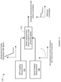
- FIG. 7 shows one example scheme for fusing GNSS data 142 and visual heading data 140 using a complementary filter with the filter cross-over frequencies scheduled with speed.
- a speed to frequency mapping operation 180 may convert the speed of vehicle 50 into a frequency signal. For example, mapping 180 may apply a weighting to a vehicle speed identified in the GPS data to generate a frequency value.
- the GPS heading data 142 is into a low pass filter 182 and visual heading data 140 is feed into a high pass filter 184.
- GPS velocity heading information 142 becomes less reliable at slower speeds and requires more low-pass filtering.
- GPS data 142 does not provide accurate heading information and is completely filtered by low pass filter 182.
- less GPS heading data 142 is provided from low pass filter 182 and more visual heading data 140 is provided from high pass filter 184.
- less visual heading data 140 is provided from high pass filter 184 and more GPS heading data 142 is provided from low pass filter 182.
- Visual heading data 140 does not give an absolute heading (relative to north) but can provide strong heading change information, even when the vehicle is stationary.
- the GPS velocity heading data 142 can provide absolute (i.e. relative to north) information while the visual heading data 140 can provide strong heading change information.
- the frequency from mapping operation 180 decreases in complementary filters 182 and 184 until fused heading 186 fully relies on visual heading data 140.
- the cross-over frequency from frequency mapping operation 180 increases causing fused heading 186 to rely more on the now stronger GPS heading information 142.
- FIG. 8 shows how fusion operation 146 may generate a fused heading 198.
- Fused heading 186 derived in FIG. 7 is fed into a low pass filter 194.
- a gyroscope yaw rate from IMU data 144 is fed into an integrator 192 to produce a yaw angle.
- the yaw angle is fed into a high pass filter 196.
- Inertial sensor data 144 is a useful source of high rate heading rate measurements.
- heading estimates from integrating the inertial rate measurements in integration 192 suffer from drift due to accumulation of small errors in the heading rate measurements. This drift needs to be constrained with absolute heading measurements.
- GPS heading measurements are used as a source of heading corrections, no heading information can be obtained when the vehicle is stationary, in this condition the heading estimates fully rely on the inertial information 144 so the heading estimates will drift.
- Complementary filters 194 and 196 handle this data fusion.
- Fused heading 186 from the complementary filters fusing GPS and visual headings in FIG. 7 provide the absolute heading reference.
- the absolute heading reference is then used to constrain the drift from integrating the gyro heading rate information 144.
- the absolute heading reference 186 can be used even when vehicle 50 is stationary, due to the complementary information obtained from the different visual and GNSS heading information.
- complementary filters 194 and 196 may filter out the low frequency IMU data 144 with less inaccurate information due to low frequency drift and may filter less of the high frequency IMU data 144 which is more accurate.
- FIG. 9 shows for explanatory purposes how a Kalman filter 200 can be used for fusing GPS heading data 142 and visual heading data 140 with IMU measurement data 144.
- Kalman filter 200 may include a prediction stage that uses the IMU measurements 144 to predict a next forward vehicle heading 206.
- Kalman filter 200 may include an update stage 202 that uses GPS heading 142 and visual heading 140 to constrain the drift in IMU data 144.
- Kalman filter 200 may fuse heading measurements 140, 142, and 144 at the same time with each measurement weighted according to an estimated uncertainty around the measurement. This allows Kalman filter 200 to internally correct a current internal heading estimate using the best available sensor source to produce an overall improved estimate.
- the estimated uncertainty of GPS heading measurements 142 may be based on the speed of vehicle 50.
- the estimated uncertainty of visual heading data 140 may be constant relative to speed but may vary over time or distance.
- FIG. 10 shows for explanatory purposes another technique for determining heading where GPS and visual measurements are not fused together.
- GPS heading measurement data 142 and visual heading measurement data are both fed into a switching operation 210 performed by fusion orientation operation 146.
- Switching operation 210 also receives a current vehicle speed.
- switching operation 210 selects one of measurements 142 or 140 with a current lowest uncertainty (highest certainty). For example, at low speeds or stationary conditions, switching operation 210 may select visual heading measurements 140 for determining the vehicle heading. At higher speeds, switching operation 210 may select GPS heading measurements 142 for determining the vehicle heading.
- FIG. 11 shows a cascaded fusion operation.
- GPS heading measurement data 142 and visual heading measurement data 140 is fed into the complimentary low pass and high pass filters 182 and 184, respectively, as previously shown in FIG. 7 .
- the fused heading data 186 from complimentary filters 182 and 184 and IMU measurement data 144 are fed into complimentary low pass and high pass filters 194 and 196, respectively, shown in FIG. 8 .
- the cascaded complimentary filtering fuses all of the different sensor heading data 140-144 together into a fused heading 198.
- FIG. 12 shows an example complementary filter cascaded with a Kalman filter.
- GPS heading measurement data 142 and visual heading measurement data is fused together by complementary filters 182 and 184.
- the output of complementary filters 182, 184 is fed into Kalman filter 200 and IMU measurement data 144 is fed into Kalman filter 200.
- Kalman filter 200 estimates the vehicle heading and/or other vehicle states based on fused GPS measurement data 142, visual measurement data 140, and IMU measurement data 144.
- control system 100 may not be able to initialize the heading directly from GNSS data.
- Control system 100 may use GNSS heading data stored for a previous driven path to align the vehicle heading with the course over ground and the true north heading.
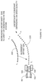
- FIG. 13 shows how control system 100 may align a vision path to a GNSS path after a path history length.
- GNSS 108 may detect a vehicle POS over a path 210 indicated with X's and camera 102 may detect a vehicle pos and orientation over a path 212 indicated by circles with arrows.
- Control system 100 may initialize and align the relative vision heading indicated by path 212 to the north GNSS heading indicated by path 210.
- a polynomial or spline function 214 is fitted to a previous traveled distance, such as the last 10 meters driven by vehicle 50.
- Polynomial or spline function 214 provides robust information about the course over ground traveled by vehicle 50 even at low speed.
- control system 100 estimates and corrects a bias on vision heading 212.
- the vision bias may be frequently updated to avoid big jumps in the vision measurements.
- visual heading measurements 212 are produced relative to some initial heading condition while GPS velocity heading measurements 210 are relative to absolute north.
- control system 100 aligns visual heading 210 and true north. The true north alignment is also updated to account for any accrued visual drift while vehicle 50 is in operation.
- Control system 100 may use the visual data to determine the crab angle between GNSS path 210 and an actual course over ground path of vehicle 50. Control system 100 may also assume no crab angle for appropriate vehicle types and when appropriate operating conditions are met. Control system 100 also may measure crab angle using a sensor that measures the velocity of the vehicle in the body frame compared with the velocity of the vehicle in the GPS frame.
- Control system 100 derives GPS velocity heading measurements 210 from the motion of the GNSS antenna 108 attached to vehicle 50.
- Control system 100 derives visual heading measurements 212 based on the orientation vehicle 50 is facing. These two angles (vehicle heading vs velocity heading) do not need to be the same. For example, vehicle 50 might not be traveling in the direction it is facing. A clear example of this is when vehicle 50 is traveling in reverse. While traveling in reverse, vehicle heading and velocity heading measurements are 180 degrees away from each other. A less serve case would be when vehicle 50 is side-slipping due to vehicle under or over-steer in a turn or has a crab angle due to the slope of the terrain.
- Control system 100 uses the crab angle to align visual heading measurements 212 with the GPS measurements 210. It is possible to measure this sideslip angle by estimating the velocity vector of the direction of motion relative to the vehicle frame (i.e. motion direction of the camera). In another example, control system may use an assumption about the motion such as a zero side-slip condition. Once determined, control system 100 may use the sideslip angle to align visual heading measurements 212 with GPS velocity heading measurements 210.
- FIG. 14 shows how control system 100 estimates the GPS course heading based on a time history of GPS positions.
- Control system 100 may not be able to use GPS velocity heading 220 at low speeds due to the amount of noise on the measurements.
- Visual heading data 222 must first be aligned with GNSS data 220. In other words, both GNSS heading data 220 and visual heading data 222 are operating in a same north-east frame of reference.
- Control system 100 may use a Kalman filter that stores a history of previous headings and positions of vehicle 50.
- the Kalman filter than combines the heading and position history data with the crab angle derived from the visual data 222 to determine a visual heading alignment offset 224 between GNSS data 220 and visual data 222.
- control system 100 continuously corrects the visual heading measurements 222 based on the alignment offset 224. Control system 100 then uses the corrected/aligned visual heading measurement 222 in-place of GPS measurements 220 when the GPS measurements 220 are unavailable.
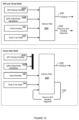
- FIG. 15 shows how a Kalman filter is used to estimate vehicle heading from GPS and visual measurements.
- a GPS velocity heading 142A and a GPS position heading 142B from the GNSS sensor 108 are input into Kalman filter 200.
- a visual heading 140 from camera 102 and a body crab angle 234 determined from visual data 140 are also input into Kalman filter 200.
- Kalman filter 200 generates the heading 230 as described above.
- Kalman filter 200 can estimate the visual to GPS alignment 232 when both GNSS 108 and camera 102 measurements sources are available.
- the top block in FIG. 15 shows a GPS and visual mode where both GPS measurement data 142 and visual measurement data 140 is available and used by Kalman filter 200 to determine heading 230.
- Kalman filter 200 at the same time also uses crab angle 234 to determine alignment 232 that aligns visual heading 140 with GPS heading 142.
- the bottom block in FIG. 15 shows a visual only mode where GPS heading data 142 is no longer available when the vehicle is stopped or operating at a very slow speed, such as less than 1 km/h. If GPS measurements 142 become unreliable, Kalman filter 200 can use the last estimated alignment 232 with visual heading measurements 140 to keep heading estimate 230 constrained.
- the camera system described above allows the vehicle to continue auto steering with high precision even if GNSS is lost for a shorter period of time. This is especially relevant on headlands where there is often a tree line that can block the view to the satellites. With automatic turning on the headland it is desired to have good positioning also on the headland.
- the control system may use visual data 140 in combination with SLAM for a field and compare items identified in the map with visually detected features to eliminate the drift problem.
- Items causing blockage or causing multipath of GNSS data is often high obstructions like buildings, trees, windmills, power line towers, etc. These obstructions are also very good visual landmarks that are different from other visual features in the field. A field is often driven in the same path year after year. This is also a benefit for the system since the visual features will most often need to be recognized from similar directions.
- Computer-readable storage medium (or alternatively, “machine-readable storage medium”) used in control system 100 may include any type of memory, as well as new technologies that may arise in the future, as long as they may be capable of storing digital information in the nature of a computer program or other data, at least temporarily, in such a manner that the stored information may be "read” by an appropriate processing device.
- the term “computer-readable” may not be limited to the historical usage of “computer” to imply a complete mainframe, mini-computer, desktop, wireless device, or even a laptop computer. Rather, “computer-readable” may comprise storage medium that may be readable by a processor, processing device, or any computing system. Such media may be any available media that may be locally and/or remotely accessible by a computer or processor, and may include volatile and non-volatile media, and removable and non-removable media.
Landscapes
- Engineering & Computer Science (AREA)
- Radar, Positioning & Navigation (AREA)
- Remote Sensing (AREA)
- Physics & Mathematics (AREA)
- General Physics & Mathematics (AREA)
- Computer Networks & Wireless Communication (AREA)
- Automation & Control Theory (AREA)
- Aviation & Aerospace Engineering (AREA)
- Life Sciences & Earth Sciences (AREA)
- Mechanical Engineering (AREA)
- Environmental Sciences (AREA)
- Computer Vision & Pattern Recognition (AREA)
- Multimedia (AREA)
- Electromagnetism (AREA)
- Soil Sciences (AREA)
- Navigation (AREA)
- Position Fixing By Use Of Radio Waves (AREA)
Claims (12)
- Système de commande pour la fusion de différentes données de capteurs afin de déterminer une orientation d'un véhicule, comprenant :
un processeur matériel pour :recevoir des données de cap visuelles (140) pour le véhicule (50) provenant d'un système de caméra (102) ;recevoir des données de cap (142) d'un système global de navigation par satellite (GNSS) (global navigation satellite system) provenant d'un système GNSS (108) ;recevoir des données de cap (144) d'une centrale à inertie (IMU) (inertial measurement unit) pour le véhicule (50) provenant d'une IMU (110) ;surveiller une vitesse du véhicule (50) ;attribuer des pondérations aux données de cap visuelles (140), aux données de cap GNSS (142) et aux données de cap IMU (144) sur la base des conditions de fonctionnement du véhicule (50), qui changent la précision associée aux données de cap visuelles (140), aux données de cap GNSS (142) et aux données de cap IMU (144),- des pondérations plus faibles étant attribuées aux données de cap GNSS (142) lorsque le véhicule (50) se déplace à une vitesse inférieure à une valeur donnée,- une pondération plus élevée étant attribuée aux données de cap GNSS (142) lorsque le véhicule (50) se déplace à des vitesses plus élevées,- une pondération égale à zéro étant attribuée aux données de cap GNSS (142), et seules les données de cap visuelles (140) étant utilisées pour déterminer le cap (130) du véhicule (50) lorsque le véhicule (50) est à l'arrêt ; etutiliser les données de cap visuelles pondérées (140), les données de cap GNSS pondérées (142) et les données de cap IMU pondérées (144) pour déterminer un cap (130) du véhicule (50), le véhicule (50) étant dirigé sur la base du cap (130) du véhicule (50). - Système selon la revendication 1, dans lequel le processeur matériel est en outre réalisé de manière à :recevoir des données de position visuelles pour le véhicule (50) provenant du système de caméra (102) ;recevoir des données de position GNSS provenant du système GNSS (108) ;attribuer des pondérations aux données de position visuelles et aux données de position GNSS sur la base des conditions de fonctionnement du véhicule (50) ; etutiliser les données de position visuelles pondérées et les données de position GNSS pondérées pour déterminer une position du véhicule (50).
- Système selon l'une des revendications précédentes, dans lequel le processeur matériel est en outre réalisé de manière à :générer en continu des corrections de dérive visuelles entre les données de cap visuelles (140) et les données de cap GNSS (142) lorsque les données de cap GNSS (142) sont disponibles ;surveiller une distance parcourue par le véhicule (50) ;attribuer des pondérations plus faibles aux données de cap visuelles (140) lorsque le véhicule (50) parcourt de plus longues distances entre les corrections de dérive visuelles ; etutiliser les données de cap visuelles (140) sans aucune pondération attribuée pour déterminer le cap (130) du véhicule (50) lorsque les données de cap GNSS (142) ne sont pas disponibles.
- Système selon l'une des revendications précédentes, dans lequel le processeur matériel est en outre réalisé de manière à :identifier un taux de dérive pour l'IMU (110) ; etattribuer une pondération aux données de cap IMU (144) sur la base du taux de dérive.
- Système selon l'une des revendications précédentes, dans lequel le processeur matériel est en outre réalisé de manière à :estimer un biais de l'IMU (110) sur le véhicule (50) sur la base des données de cap visuelles (140) ; etcalibrer l'IMU (110) sur la base du biais estimé.
- Système selon l'une des revendications précédentes, dans lequel le processeur matériel est en outre réalisé de manière à aligner le cap (130) du véhicule (50) par rapport à un nord géographique (N) sur la base d'un trajet parcouru précédent du véhicule (50).
- Système selon l'une des revendications précédentes, dans lequel le processeur matériel est en outre réalisé de manière à initialiser et mettre à jour le cap (130) du véhicule (50) sur la base d'une carte avec des caractéristiques visuelles stockées (104) que le système de caméra (102) reconnaît et utilise pour générer les données de cap visuelles (140).
- Système selon l'une des revendications précédentes, dans lequel le processeur matériel est en outre réalisé de manière à estimer une dérive dans les données de cap visuelles (140) en analysant en continu une partie précédente d'un trajet parcouru par le véhicule (50).
- Système selon la revendication 8, dans lequel le processeur matériel est en outre réalisé de manière à :cesser d'utiliser les données de cap GNSS (142) pour déterminer le cap (130) du véhicule (50) lorsqu'un seuil de fiabilité pour les données de cap GNSS (142) tombe en dessous d'une valeur seuil ;corriger les données de cap visuelles (140) sur la base de la dérive estimée ; etutiliser les données de cap visuelles corrigées (140), sans les données de cap GNSS (142), pour diriger le véhicule (50).
- Programme informatique pour calculer un cap d'un véhicule (50), le programme informatique comprenant un ensemble d'instructions apte à être mis en œuvre de manière à :recevoir des données de cap visuelles (140) pour le véhicule (50) provenant d'un système de caméra (102) ;recevoir des données de cap d'un système global de navigation par satellite (GNSS) provenant d'un système GNSS (108) ;recevoir des données de cap d'une centrale à inertie (IMU 110) provenant d'une IMU (110) ; etsurveiller les conditions de fonctionnement du véhicule (50) qui réduisent la fiabilité des données de cap visuelles (140), des données de cap GNSS (142) et des données de cap IMU (144) ;utiliser différentes combinaisons et pondérations des données de cap visuelles (140), des données de cap GNSS (142) et des données de cap IMU (144) pour déterminer un cap (130) du véhicule (50) et compenser les conditions de fonctionnement qui réduisent la fiabilité des données de cap visuelles (140), des données de cap GNSS (142) et des données de cap IMU (144) ;générer un signal de fréquence qui varie sur la base d'une vitesse du véhicule (50) ;entrer le signal de fréquence dans un filtre passe-bas (182) et un filtre passe-haut (184) qui sont complémentaires et utiliser le filtre passe-bas (182) et le filtre passe-haut (184) qui sont complémentaires avec des fréquences de croisement de filtre prévues sur la base de la vitesse ;entrer les données de cap GNSS (142) dans le filtre passe-bas (182) ;entrer les données de cap visuelles (140) dans le filtre passe-haut (184) ; etutiliser un cap fusionné (186) issu du filtre passe-bas (182) et du filtre passe-haut (184) qui sont complémentaires pour déterminer le cap (130) du véhicule.
- Programme informatique selon la revendication 10, l'ensemble d'instructions étant en outre apte à être mis en œuvre de manière à :générer un deuxième signal de fréquence sur la base de la constante de temps du taux de dérive associée à l'IMU (110) ;utiliser le deuxième signal de fréquence pour déterminer les fréquences de croisement d'un deuxième filtre passe-bas (194) et d'un deuxième filtre passe-haut (196) qui sont complémentaires ;entrer le cap fusionné (186) dans le deuxième filtre passe-bas (194) ;entrer un taux de lacet intégré à partir des données de cap IMU (144) dans le deuxième filtre passe-haut (196) ; etutiliser une sortie du deuxième filtre passe-bas (194) et du deuxième filtre passe-haut (196) qui sont complémentaires pour déterminer le cap (130) du véhicule.
- Programme informatique selon la revendication 11, l'ensemble d'instructions étant en outre apte à être mis en œuvre de manière à :entrer le cap fusionné (186) dans un filtre de Kalman (200) ;entrer les données de cap IMU (144) dans le filtre de Kalman (200) ; etutiliser le filtre de Kalman (200) pour déterminer le cap (130) du véhicule sur la base du cap fusionné (186) et du cap de l'IMU (110).
Applications Claiming Priority (2)
| Application Number | Priority Date | Filing Date | Title |
|---|---|---|---|
| US201662403364P | 2016-10-03 | 2016-10-03 | |
| PCT/US2017/054786 WO2018067473A1 (fr) | 2016-10-03 | 2017-10-02 | Utilisation de capteurs optiques pour résoudre des problèmes de cap de véhicule |
Publications (2)
| Publication Number | Publication Date |
|---|---|
| EP3519768A1 EP3519768A1 (fr) | 2019-08-07 |
| EP3519768B1 true EP3519768B1 (fr) | 2025-04-30 |
Family
ID=60084123
Family Applications (1)
| Application Number | Title | Priority Date | Filing Date |
|---|---|---|---|
| EP17784508.8A Active EP3519768B1 (fr) | 2016-10-03 | 2017-10-02 | Utilisation de capteurs optiques pour résoudre des problèmes de cap de véhicule |
Country Status (6)
| Country | Link |
|---|---|
| US (1) | US10579068B2 (fr) |
| EP (1) | EP3519768B1 (fr) |
| AU (1) | AU2017339857B2 (fr) |
| BR (1) | BR112019006526A2 (fr) |
| CA (1) | CA3033278A1 (fr) |
| WO (1) | WO2018067473A1 (fr) |
Families Citing this family (41)
| Publication number | Priority date | Publication date | Assignee | Title |
|---|---|---|---|---|
| US10983206B2 (en) * | 2017-11-07 | 2021-04-20 | FLIR Belgium BVBA | Low cost high precision GNSS systems and methods |
| EP3642683B1 (fr) | 2017-06-22 | 2022-12-14 | Agjunction LLC | Système d'image 3d pour commande de véhicule |
| KR102441073B1 (ko) * | 2017-10-23 | 2022-09-06 | 현대자동차주식회사 | 자이로 센싱값 보상 장치, 그를 포함한 시스템 및 그 방법 |
| US20190196025A1 (en) * | 2017-12-21 | 2019-06-27 | Honda Motor Co., Ltd. | System and method for vehicle path estimation using vehicular communication |
| US10830906B2 (en) * | 2017-12-28 | 2020-11-10 | Automotive Research & Testing Center | Method of adaptive weighting adjustment positioning |
| WO2019138640A1 (fr) * | 2018-01-10 | 2019-07-18 | ソニー株式会社 | Dispositif de traitement d'informations, procédé de traitement d'informations, et programme |
| US20190217674A1 (en) * | 2018-01-16 | 2019-07-18 | Saf-Holland, Inc. | Multi-vehicle articulation angle sensing arrangement |
| DK3764765T3 (da) * | 2018-03-13 | 2022-07-18 | Moog Inc | Autonomt navigationssystem og dermed udstyret køretøj |
| DE102018206786A1 (de) * | 2018-05-03 | 2019-11-07 | Robert Bosch Gmbh | Verfahren zur satellitengestützten Ermittlung einer Fahrzeugposition mittels eines Bewegungs- und Positionssensors |
| US10753752B2 (en) | 2018-07-26 | 2020-08-25 | Trimble Inc. | Vehicle manual guidance systems with steering wheel angle sensors and road wheel angle sensors |
| JP7223542B2 (ja) * | 2018-10-03 | 2023-02-16 | 古野電気株式会社 | 航法装置、航行支援情報の生成方法、および、航行支援情報の生成プログラム |
| CN109725339B (zh) * | 2018-12-20 | 2024-10-18 | 东莞市普灵思智能电子有限公司 | 一种紧耦合的自动驾驶感知方法及系统 |
| KR102206388B1 (ko) | 2019-01-31 | 2021-01-22 | 엘지전자 주식회사 | 이동 로봇 및 이의 제어 방법 |
| US11199410B2 (en) | 2019-04-30 | 2021-12-14 | Stmicroelectronics, Inc. | Dead reckoning by determining misalignment angle between movement direction and sensor heading direction |
| US11747142B2 (en) * | 2019-04-30 | 2023-09-05 | Stmicroelectronics, Inc. | Inertial navigation system capable of dead reckoning in vehicles |
| CN110502005B (zh) * | 2019-07-12 | 2024-10-18 | 北京合众思壮科技股份有限公司 | 自动驾驶方法及系统 |
| FI20195678A1 (fi) * | 2019-08-14 | 2021-02-15 | Ponsse Oyj | Menetelmä ja järjestelmä metsäkoneessa |
| CN110632633A (zh) * | 2019-09-29 | 2019-12-31 | 成都云科新能汽车技术有限公司 | 一种车载集成式高精度定位设备及定位方法 |
| US12038759B2 (en) | 2020-03-05 | 2024-07-16 | Analog Devices, Inc. | Trusted motion unit |
| DE102021104935B4 (de) * | 2020-03-05 | 2025-07-03 | Analog Devices, Inc. | Vertrauenswürdige Bewegungseinheit |
| US11337356B2 (en) * | 2020-03-12 | 2022-05-24 | Deere & Company | Crop orientation system and method |
| CA3195070A1 (fr) * | 2020-10-26 | 2022-05-05 | Precision Planting Llc | Outil a conduite automatisee |
| CN112230666B (zh) * | 2020-10-30 | 2024-06-07 | 上海海事大学 | 一种基于自适应扩展状态观测器的漂角修正航向控制方法 |
| CN114518108B (zh) * | 2020-11-18 | 2023-09-08 | 宇通客车股份有限公司 | 一种定位地图构建方法及装置 |
| KR20220068710A (ko) | 2020-11-19 | 2022-05-26 | 삼성전자주식회사 | 차량 측위 방법 및 장치 |
| JP7144504B2 (ja) * | 2020-12-28 | 2022-09-29 | 本田技研工業株式会社 | 車両制御システム |
| US11609093B2 (en) * | 2021-06-07 | 2023-03-21 | Honeywell International Inc. | Position probability density function filter to determine real-time measurement errors for map based, vision navigation systems |
| CN113720336B (zh) * | 2021-08-10 | 2022-11-22 | 广东汇天航空航天科技有限公司 | 一种航向信息确定方法、车辆以及计算机可读存储介质 |
| US12085955B2 (en) | 2021-10-19 | 2024-09-10 | Deere & Company | Methods, apparatus, and articles of manufacture to select track paths for one or more vehicles in a field |
| DE102022200349B3 (de) * | 2022-01-14 | 2023-02-09 | Continental Autonomous Mobility Germany GmbH | Verfahren zur Positionsbestimmung eines Kraftfahrzeugs, Fahrsystem und Kraftfahrzeug |
| FR3133232B1 (fr) * | 2022-03-04 | 2024-03-01 | Safran | Procédé et dispositif d’aide à la navigation basée sur un filtre de Kalman |
| JP7837795B2 (ja) * | 2022-05-11 | 2026-03-31 | ヤンマーホールディングス株式会社 | 自動走行方法、自動走行システム、及び自動走行プログラム |
| JP7753995B2 (ja) * | 2022-06-16 | 2025-10-15 | 株式会社デンソー | 状態推定装置、状態推定方法 |
| JP7781738B2 (ja) * | 2022-12-28 | 2025-12-08 | 株式会社クボタ | 作業車両、作業車両の制御システムおよび制御方法 |
| CN116295436B (zh) * | 2023-03-31 | 2026-02-24 | 武汉大学 | 一种低成本嵌入式gnss/ins组合导航时间同步算法 |
| US12579662B2 (en) | 2023-06-15 | 2026-03-17 | Oracle International Corporation | High-precision localization of a moving object on a trajectory |
| DE102023119096A1 (de) | 2023-07-19 | 2025-01-23 | Deere & Company | Verfahren zur Kalibrierung der Positionierung und/oder Ausrichtung eines an einem landwirtschaftlichen Fahrzeug angebrachten optischen Erfassungssystems und entsprechende Anordnung |
| DE102023119302A1 (de) | 2023-07-21 | 2025-01-23 | Deere & Company | Anordnung zur Führung eines landwirtschaftlichen Fahrzeugs über ein Feld mit Sensorfusion und entsprechendes Verfahren |
| DE102023120383A1 (de) | 2023-08-01 | 2025-02-06 | Deere & Company | Anordnung zur Erkennung einer eventuellen Abweichung eines landwirtschaftlichen Fahrzeugs von einem Sollweg bei einer Bearbeitung von in Reihen angebauten Pflanzen, entsprechendes Fahrzeug und Verfahren |
| US12608825B2 (en) | 2023-09-12 | 2026-04-21 | Oracle International Corporation | Preparing data for high-precision absolute localization of a moving object along a trajectory |
| US20250085434A1 (en) * | 2023-09-12 | 2025-03-13 | Oracle International Corporation | Preparing data for high-precision absolute localization of a moving object along a trajectory |
Citations (6)
| Publication number | Priority date | Publication date | Assignee | Title |
|---|---|---|---|---|
| US20020158796A1 (en) * | 2001-04-25 | 2002-10-31 | Ian Humphrey | Integrated GPS and IGS system and method |
| US20060149417A1 (en) * | 2005-01-04 | 2006-07-06 | Deere & Company, A Delaware Corporation | Vision-aided system and method for guiding a vehicle |
| EP2095148A1 (fr) * | 2006-11-06 | 2009-09-02 | Tele Atlas B.V. | Agencement et procédé de détermination précise d'emplacements et d'orientations bidimensionnels et tridimensionnels |
| US20100030470A1 (en) * | 2008-07-02 | 2010-02-04 | O2Micro, Inc. | Global positioning system and dead reckoning (gps&dr) integrated navigation system |
| US20110178708A1 (en) * | 2010-01-18 | 2011-07-21 | Qualcomm Incorporated | Using object to align and calibrate inertial navigation system |
| WO2015085483A1 (fr) * | 2013-12-10 | 2015-06-18 | SZ DJI Technology Co., Ltd. | Fusion de capteurs |
Family Cites Families (64)
| Publication number | Priority date | Publication date | Assignee | Title |
|---|---|---|---|---|
| US5663879A (en) | 1987-11-20 | 1997-09-02 | North American Philips Corporation | Method and apparatus for smooth control of a vehicle with automatic recovery for interference |
| US5390125A (en) | 1990-02-05 | 1995-02-14 | Caterpillar Inc. | Vehicle position determination system and method |
| US5194851A (en) | 1991-02-21 | 1993-03-16 | Case Corporation | Steering controller |
| WO1995015499A1 (fr) | 1993-12-03 | 1995-06-08 | Satloc, Inc. | Systeme de guidage au sol sur des bandes de terrain par positionnement global differentiel comprenant deux rangees de rampes lumineuses et un regulateur de debit, et procede associe |
| FI942218A0 (fi) | 1994-05-13 | 1994-05-13 | Modulaire Oy | Automatiskt styrningssystem foer obemannat fordon |
| US5928309A (en) | 1996-02-05 | 1999-07-27 | Korver; Kelvin | Navigation/guidance system for a land-based vehicle |
| US6070673A (en) | 1996-11-22 | 2000-06-06 | Case Corporation | Location based tractor control |
| CA2283904C (fr) | 1997-03-21 | 2007-01-09 | The Board Of Trustees Of The Leland Stanford Junior University | Systeme de navigation a precision centimetrique utilisant des satellites en orbite basse |
| US6052647A (en) | 1997-06-20 | 2000-04-18 | Stanford University | Method and system for automatic control of vehicles based on carrier phase differential GPS |
| US6212453B1 (en) | 1998-09-11 | 2001-04-03 | Honda Giken Kogyo Kabushiki Kaisha | Vehicle steering control system |
| US6445983B1 (en) | 2000-07-07 | 2002-09-03 | Case Corporation | Sensor-fusion navigator for automated guidance of off-road vehicles |
| US6377889B1 (en) | 2000-10-13 | 2002-04-23 | Trimble Navigation Limited | Non-linear method of guiding to arbitrary curves with adaptive feedback |
| US6539303B2 (en) | 2000-12-08 | 2003-03-25 | Mcclure John A. | GPS derived swathing guidance system |
| US6711501B2 (en) | 2000-12-08 | 2004-03-23 | Satloc, Llc | Vehicle navigation system and method for swathing applications |
| US6819780B2 (en) | 2001-02-02 | 2004-11-16 | Cnh America Llc | Method and apparatus for automatically steering a vehicle in an agricultural field using a plurality of fuzzy logic membership functions |
| AUPR430301A0 (en) | 2001-04-09 | 2001-05-17 | Agsystems Pty Ltd | Soil-cultivation implement control apparatus and method |
| AUPR733701A0 (en) | 2001-08-29 | 2001-09-20 | Beeline Technologies | Apparatus and method for assisted navigation of a land vehicle |
| US6865465B2 (en) | 2002-05-06 | 2005-03-08 | Csi Wireless, Inc. | Method and system for implement steering for agricultural vehicles |
| US7689354B2 (en) | 2003-03-20 | 2010-03-30 | Hemisphere Gps Llc | Adaptive guidance system and method |
| US7400956B1 (en) | 2003-03-20 | 2008-07-15 | Hemisphere Gps Inc. | Satellite position and heading sensor for vehicle steering control |
| US7437230B2 (en) | 2003-03-20 | 2008-10-14 | Hemisphere Gps Llc | Satellite based vehicle guidance control in straight and contour modes |
| US7142956B2 (en) | 2004-03-19 | 2006-11-28 | Hemisphere Gps Llc | Automatic steering system and method |
| US7162348B2 (en) | 2002-12-11 | 2007-01-09 | Hemisphere Gps Llc | Articulated equipment position control system and method |
| US7885745B2 (en) | 2002-12-11 | 2011-02-08 | Hemisphere Gps Llc | GNSS control system and method |
| US8639416B2 (en) | 2003-03-20 | 2014-01-28 | Agjunction Llc | GNSS guidance and machine control |
| US8594879B2 (en) | 2003-03-20 | 2013-11-26 | Agjunction Llc | GNSS guidance and machine control |
| US8634993B2 (en) | 2003-03-20 | 2014-01-21 | Agjunction Llc | GNSS based control for dispensing material from vehicle |
| US9002565B2 (en) | 2003-03-20 | 2015-04-07 | Agjunction Llc | GNSS and optical guidance and machine control |
| US8214111B2 (en) | 2005-07-19 | 2012-07-03 | Hemisphere Gps Llc | Adaptive machine control system and method |
| US8190337B2 (en) | 2003-03-20 | 2012-05-29 | Hemisphere GPS, LLC | Satellite based vehicle guidance control in straight and contour modes |
| US6789014B1 (en) | 2003-05-09 | 2004-09-07 | Deere & Company | Direct modification of DGPS information with inertial measurement data |
| US8583315B2 (en) | 2004-03-19 | 2013-11-12 | Agjunction Llc | Multi-antenna GNSS control system and method |
| US7242791B2 (en) * | 2005-01-04 | 2007-07-10 | Deere & Company | Method and system for guiding a vehicle with vision enhancement |
| US20060167600A1 (en) | 2005-01-27 | 2006-07-27 | Raven Industries, Inc. | Architecturally partitioned automatic steering system and method |
| US7835832B2 (en) | 2007-01-05 | 2010-11-16 | Hemisphere Gps Llc | Vehicle control system |
| US8311696B2 (en) | 2009-07-17 | 2012-11-13 | Hemisphere Gps Llc | Optical tracking vehicle control system and method |
| US8768558B2 (en) | 2007-01-05 | 2014-07-01 | Agjunction Llc | Optical tracking vehicle control system and method |
| US9002566B2 (en) | 2008-02-10 | 2015-04-07 | AgJunction, LLC | Visual, GNSS and gyro autosteering control |
| US8018376B2 (en) | 2008-04-08 | 2011-09-13 | Hemisphere Gps Llc | GNSS-based mobile communication system and method |
| EP2135498B1 (fr) | 2008-06-20 | 2012-06-20 | AGROCOM GmbH & Co. Agrarsystem KG | Procédé de navigation d'un véhicule agricole et véhicule agricole |
| US8386129B2 (en) | 2009-01-17 | 2013-02-26 | Hemipshere GPS, LLC | Raster-based contour swathing for guidance and variable-rate chemical application |
| US8126620B2 (en) | 2009-04-28 | 2012-02-28 | Cnh America Llc | Grain transfer control system and method |
| US8401704B2 (en) | 2009-07-22 | 2013-03-19 | Hemisphere GPS, LLC | GNSS control system and method for irrigation and related applications |
| US8649930B2 (en) | 2009-09-17 | 2014-02-11 | Agjunction Llc | GNSS integrated multi-sensor control system and method |
| US9173337B2 (en) | 2009-10-19 | 2015-11-03 | Efc Systems, Inc. | GNSS optimized control system and method |
| US8548649B2 (en) | 2009-10-19 | 2013-10-01 | Agjunction Llc | GNSS optimized aircraft control system and method |
| US8583326B2 (en) | 2010-02-09 | 2013-11-12 | Agjunction Llc | GNSS contour guidance path selection |
| US8676620B2 (en) | 2010-05-28 | 2014-03-18 | Agjunction Llc | System and method for workorder management |
| WO2012009269A2 (fr) | 2010-07-12 | 2012-01-19 | Gvm, Inc. | Système et procédé permettant de collecter des échantillons de terre |
| US8803735B2 (en) | 2010-11-19 | 2014-08-12 | Agjunction Llc | Portable base station network for local differential GNSS corrections |
| US9803983B2 (en) * | 2010-12-03 | 2017-10-31 | Qualcomm Incorporated | Inertial sensor aided heading and positioning for GNSS vehicle navigation |
| US8589013B2 (en) | 2011-10-25 | 2013-11-19 | Jaybridge Robotics, Inc. | Method and system for dynamically positioning a vehicle relative to another vehicle in motion |
| US8781685B2 (en) | 2012-07-17 | 2014-07-15 | Agjunction Llc | System and method for integrating automatic electrical steering with GNSS guidance |
| US10131376B2 (en) | 2013-01-30 | 2018-11-20 | Agjunction Llc | Steering controller for precision farming |
| US9162703B2 (en) | 2013-01-30 | 2015-10-20 | AgJunction, LLC | Steering controller for precision farming |
| US9781915B2 (en) | 2013-03-14 | 2017-10-10 | Agjunction Llc | Implement and boom height control system and method |
| US9223314B2 (en) | 2013-03-14 | 2015-12-29 | Aglunction, LLC | Hovering control for helicopters using a GNSS vector |
| US9945957B2 (en) | 2013-03-14 | 2018-04-17 | Agjunction Llc | Machine control system and method |
| US9476734B2 (en) * | 2013-03-15 | 2016-10-25 | Innovative Solutions And Support, Inc. | Systems and methods for calibrating and adjusting a heading reference system |
| US20140266877A1 (en) | 2013-03-15 | 2014-09-18 | Agjunction Llc | Precision accuracy global navigation satellite system (gnss) with smart devices |
| US9251587B2 (en) * | 2013-04-05 | 2016-02-02 | Caterpillar Inc. | Motion estimation utilizing range detection-enhanced visual odometry |
| US9719801B1 (en) * | 2013-07-23 | 2017-08-01 | Waymo Llc | Methods and systems for calibrating sensors using road map data |
| US9733643B2 (en) | 2013-12-20 | 2017-08-15 | Agjunction Llc | Hydraulic interrupter safety system and method |
| US9857478B2 (en) | 2015-01-27 | 2018-01-02 | Agjunction Llc | Apparatus and method to mount steering actuator |
-
2017
- 2017-10-02 EP EP17784508.8A patent/EP3519768B1/fr active Active
- 2017-10-02 US US15/722,916 patent/US10579068B2/en active Active
- 2017-10-02 CA CA3033278A patent/CA3033278A1/fr active Pending
- 2017-10-02 BR BR112019006526A patent/BR112019006526A2/pt not_active Application Discontinuation
- 2017-10-02 AU AU2017339857A patent/AU2017339857B2/en active Active
- 2017-10-02 WO PCT/US2017/054786 patent/WO2018067473A1/fr not_active Ceased
Patent Citations (6)
| Publication number | Priority date | Publication date | Assignee | Title |
|---|---|---|---|---|
| US20020158796A1 (en) * | 2001-04-25 | 2002-10-31 | Ian Humphrey | Integrated GPS and IGS system and method |
| US20060149417A1 (en) * | 2005-01-04 | 2006-07-06 | Deere & Company, A Delaware Corporation | Vision-aided system and method for guiding a vehicle |
| EP2095148A1 (fr) * | 2006-11-06 | 2009-09-02 | Tele Atlas B.V. | Agencement et procédé de détermination précise d'emplacements et d'orientations bidimensionnels et tridimensionnels |
| US20100030470A1 (en) * | 2008-07-02 | 2010-02-04 | O2Micro, Inc. | Global positioning system and dead reckoning (gps&dr) integrated navigation system |
| US20110178708A1 (en) * | 2010-01-18 | 2011-07-21 | Qualcomm Incorporated | Using object to align and calibrate inertial navigation system |
| WO2015085483A1 (fr) * | 2013-12-10 | 2015-06-18 | SZ DJI Technology Co., Ltd. | Fusion de capteurs |
Also Published As
| Publication number | Publication date |
|---|---|
| US20180095476A1 (en) | 2018-04-05 |
| WO2018067473A1 (fr) | 2018-04-12 |
| AU2017339857A1 (en) | 2019-02-28 |
| AU2017339857B2 (en) | 2021-09-16 |
| BR112019006526A2 (pt) | 2019-06-25 |
| EP3519768A1 (fr) | 2019-08-07 |
| CA3033278A1 (fr) | 2018-04-12 |
| US10579068B2 (en) | 2020-03-03 |
Similar Documents
| Publication | Publication Date | Title |
|---|---|---|
| EP3519768B1 (fr) | Utilisation de capteurs optiques pour résoudre des problèmes de cap de véhicule | |
| US12554262B2 (en) | 3-D image system for vehicle control | |
| US11243081B2 (en) | Slam assisted INS | |
| US8775063B2 (en) | System and method of lane path estimation using sensor fusion | |
| Rovira-Más et al. | The role of GNSS in the navigation strategies of cost-effective agricultural robots | |
| US7840352B2 (en) | Method and system for autonomous vehicle navigation | |
| US10151588B1 (en) | Determining position and orientation for aerial vehicle in GNSS-denied situations | |
| EP2856273B1 (fr) | Estimation de pose | |
| US10753752B2 (en) | Vehicle manual guidance systems with steering wheel angle sensors and road wheel angle sensors | |
| CN108873038A (zh) | 自主泊车定位方法及定位系统 | |
| US9122278B2 (en) | Vehicle navigation | |
| US9969081B2 (en) | Method and system for the directed control of robotic assets | |
| Sun et al. | Motion model-assisted GNSS/MEMS-IMU integrated navigation system for land vehicle | |
| North et al. | Enhanced mobile robot outdoor localization using INS/GPS integration | |
| IL275325A (en) | A method for evaluating vehicle navigation data for terrain using road geometry and orientation parameters | |
| CN114279439A (zh) | 一种惯导数据的修正方法、装置和系统 | |
| CN115326094A (zh) | 一种拖拉机的自动定位方法 | |
| JP2023132340A (ja) | 移動体の位置推定装置及び観測値採用方法 | |
| Andert et al. | A flight state estimator that combines stereo-vision, INS, and satellite pseudo-ranges | |
| Mitrev et al. | Radar-inertial localization for unmanned ground vehicles in gnss-denied off-road environments | |
| Roth et al. | Application of robust, high-accuracy positioning for autonomous ground vehicles | |
| KR102739819B1 (ko) | 지리 정보 시스템 기반 추측항법 알고리즘 | |
| Stefanoni et al. | Enhancing 2D Localization Accuracy for Differential Wheeled Robots: A Fusion of Odometry, Magnetometers, and Absolute Positioning Systems | |
| Ilyas et al. | Dependable navigation in GPS denied environment: A multi-sensor fusion technique | |
| Perumal et al. | Dead Reckoning Using GPS and IMU for Accurate Position and Velocity |
Legal Events
| Date | Code | Title | Description |
|---|---|---|---|
| STAA | Information on the status of an ep patent application or granted ep patent |
Free format text: STATUS: UNKNOWN |
|
| STAA | Information on the status of an ep patent application or granted ep patent |
Free format text: STATUS: THE INTERNATIONAL PUBLICATION HAS BEEN MADE |
|
| PUAI | Public reference made under article 153(3) epc to a published international application that has entered the european phase |
Free format text: ORIGINAL CODE: 0009012 |
|
| STAA | Information on the status of an ep patent application or granted ep patent |
Free format text: STATUS: REQUEST FOR EXAMINATION WAS MADE |
|
| 17P | Request for examination filed |
Effective date: 20190430 |
|
| AK | Designated contracting states |
Kind code of ref document: A1 Designated state(s): AL AT BE BG CH CY CZ DE DK EE ES FI FR GB GR HR HU IE IS IT LI LT LU LV MC MK MT NL NO PL PT RO RS SE SI SK SM TR |
|
| AX | Request for extension of the european patent |
Extension state: BA ME |
|
| DAV | Request for validation of the european patent (deleted) | ||
| DAX | Request for extension of the european patent (deleted) | ||
| PUAG | Search results despatched under rule 164(2) epc together with communication from examining division |
Free format text: ORIGINAL CODE: 0009017 |
|
| STAA | Information on the status of an ep patent application or granted ep patent |
Free format text: STATUS: EXAMINATION IS IN PROGRESS |
|
| 17Q | First examination report despatched |
Effective date: 20210311 |
|
| B565 | Issuance of search results under rule 164(2) epc |
Effective date: 20210311 |
|
| RIC1 | Information provided on ipc code assigned before grant |
Ipc: G01C 21/16 20060101AFI20210305BHEP Ipc: G01S 19/47 20100101ALI20210305BHEP Ipc: G01S 19/49 20100101ALI20210305BHEP Ipc: A01B 69/00 20060101ALI20210305BHEP Ipc: A01B 79/00 20060101ALI20210305BHEP Ipc: G05D 1/02 20200101ALI20210305BHEP Ipc: G01C 21/20 20060101ALI20210305BHEP Ipc: A01B 69/04 20060101ALI20210305BHEP Ipc: G01S 19/39 20100101ALI20210305BHEP Ipc: G01S 19/48 20100101ALI20210305BHEP Ipc: G01S 19/52 20100101ALI20210305BHEP |
|
| RAP3 | Party data changed (applicant data changed or rights of an application transferred) |
Owner name: AGJUNCTION LLC |
|
| RIC1 | Information provided on ipc code assigned before grant |
Ipc: G05D 1/00 20060101ALI20241108BHEP Ipc: G01S 19/52 20100101ALI20241108BHEP Ipc: G01S 19/48 20100101ALI20241108BHEP Ipc: G01S 19/39 20100101ALI20241108BHEP Ipc: A01B 69/04 20060101ALI20241108BHEP Ipc: G01C 21/20 20060101ALI20241108BHEP Ipc: A01B 79/00 20060101ALI20241108BHEP Ipc: A01B 69/00 20060101ALI20241108BHEP Ipc: G01S 19/49 20100101ALI20241108BHEP Ipc: G01S 19/47 20100101ALI20241108BHEP Ipc: G01C 21/16 20060101AFI20241108BHEP |
|
| GRAP | Despatch of communication of intention to grant a patent |
Free format text: ORIGINAL CODE: EPIDOSNIGR1 |
|
| STAA | Information on the status of an ep patent application or granted ep patent |
Free format text: STATUS: GRANT OF PATENT IS INTENDED |
|
| INTG | Intention to grant announced |
Effective date: 20241220 |
|
| GRAS | Grant fee paid |
Free format text: ORIGINAL CODE: EPIDOSNIGR3 |
|
| GRAA | (expected) grant |
Free format text: ORIGINAL CODE: 0009210 |
|
| STAA | Information on the status of an ep patent application or granted ep patent |
Free format text: STATUS: THE PATENT HAS BEEN GRANTED |
|
| AK | Designated contracting states |
Kind code of ref document: B1 Designated state(s): AL AT BE BG CH CY CZ DE DK EE ES FI FR GB GR HR HU IE IS IT LI LT LU LV MC MK MT NL NO PL PT RO RS SE SI SK SM TR |
|
| REG | Reference to a national code |
Ref country code: CH Ref legal event code: EP Ref country code: GB Ref legal event code: FG4D |
|
| REG | Reference to a national code |
Ref country code: IE Ref legal event code: FG4D |
|
| REG | Reference to a national code |
Ref country code: DE Ref legal event code: R096 Ref document number: 602017089211 Country of ref document: DE |
|
| REG | Reference to a national code |
Ref country code: NL Ref legal event code: MP Effective date: 20250430 |
|
| REG | Reference to a national code |
Ref country code: AT Ref legal event code: MK05 Ref document number: 1790380 Country of ref document: AT Kind code of ref document: T Effective date: 20250430 |
|
| PG25 | Lapsed in a contracting state [announced via postgrant information from national office to epo] |
Ref country code: FI Free format text: LAPSE BECAUSE OF FAILURE TO SUBMIT A TRANSLATION OF THE DESCRIPTION OR TO PAY THE FEE WITHIN THE PRESCRIBED TIME-LIMIT Effective date: 20250430 Ref country code: PT Free format text: LAPSE BECAUSE OF FAILURE TO SUBMIT A TRANSLATION OF THE DESCRIPTION OR TO PAY THE FEE WITHIN THE PRESCRIBED TIME-LIMIT Effective date: 20250901 Ref country code: ES Free format text: LAPSE BECAUSE OF FAILURE TO SUBMIT A TRANSLATION OF THE DESCRIPTION OR TO PAY THE FEE WITHIN THE PRESCRIBED TIME-LIMIT Effective date: 20250430 |
|
| REG | Reference to a national code |
Ref country code: LT Ref legal event code: MG9D |
|
| PG25 | Lapsed in a contracting state [announced via postgrant information from national office to epo] |
Ref country code: NO Free format text: LAPSE BECAUSE OF FAILURE TO SUBMIT A TRANSLATION OF THE DESCRIPTION OR TO PAY THE FEE WITHIN THE PRESCRIBED TIME-LIMIT Effective date: 20250730 Ref country code: GR Free format text: LAPSE BECAUSE OF FAILURE TO SUBMIT A TRANSLATION OF THE DESCRIPTION OR TO PAY THE FEE WITHIN THE PRESCRIBED TIME-LIMIT Effective date: 20250731 |
|
| PG25 | Lapsed in a contracting state [announced via postgrant information from national office to epo] |
Ref country code: NL Free format text: LAPSE BECAUSE OF FAILURE TO SUBMIT A TRANSLATION OF THE DESCRIPTION OR TO PAY THE FEE WITHIN THE PRESCRIBED TIME-LIMIT Effective date: 20250430 Ref country code: PL Free format text: LAPSE BECAUSE OF FAILURE TO SUBMIT A TRANSLATION OF THE DESCRIPTION OR TO PAY THE FEE WITHIN THE PRESCRIBED TIME-LIMIT Effective date: 20250430 |
|
| PG25 | Lapsed in a contracting state [announced via postgrant information from national office to epo] |
Ref country code: BG Free format text: LAPSE BECAUSE OF FAILURE TO SUBMIT A TRANSLATION OF THE DESCRIPTION OR TO PAY THE FEE WITHIN THE PRESCRIBED TIME-LIMIT Effective date: 20250430 |
|
| PG25 | Lapsed in a contracting state [announced via postgrant information from national office to epo] |
Ref country code: HR Free format text: LAPSE BECAUSE OF FAILURE TO SUBMIT A TRANSLATION OF THE DESCRIPTION OR TO PAY THE FEE WITHIN THE PRESCRIBED TIME-LIMIT Effective date: 20250430 |
|
| PG25 | Lapsed in a contracting state [announced via postgrant information from national office to epo] |
Ref country code: AT Free format text: LAPSE BECAUSE OF FAILURE TO SUBMIT A TRANSLATION OF THE DESCRIPTION OR TO PAY THE FEE WITHIN THE PRESCRIBED TIME-LIMIT Effective date: 20250430 |
|
| PG25 | Lapsed in a contracting state [announced via postgrant information from national office to epo] |
Ref country code: RS Free format text: LAPSE BECAUSE OF FAILURE TO SUBMIT A TRANSLATION OF THE DESCRIPTION OR TO PAY THE FEE WITHIN THE PRESCRIBED TIME-LIMIT Effective date: 20250731 |
|
| PG25 | Lapsed in a contracting state [announced via postgrant information from national office to epo] |
Ref country code: IS Free format text: LAPSE BECAUSE OF FAILURE TO SUBMIT A TRANSLATION OF THE DESCRIPTION OR TO PAY THE FEE WITHIN THE PRESCRIBED TIME-LIMIT Effective date: 20250830 |
|
| PG25 | Lapsed in a contracting state [announced via postgrant information from national office to epo] |
Ref country code: LV Free format text: LAPSE BECAUSE OF FAILURE TO SUBMIT A TRANSLATION OF THE DESCRIPTION OR TO PAY THE FEE WITHIN THE PRESCRIBED TIME-LIMIT Effective date: 20250430 |
|
| PGFP | Annual fee paid to national office [announced via postgrant information from national office to epo] |
Ref country code: DE Payment date: 20251022 Year of fee payment: 9 |
|
| PG25 | Lapsed in a contracting state [announced via postgrant information from national office to epo] |
Ref country code: SM Free format text: LAPSE BECAUSE OF FAILURE TO SUBMIT A TRANSLATION OF THE DESCRIPTION OR TO PAY THE FEE WITHIN THE PRESCRIBED TIME-LIMIT Effective date: 20250430 Ref country code: DK Free format text: LAPSE BECAUSE OF FAILURE TO SUBMIT A TRANSLATION OF THE DESCRIPTION OR TO PAY THE FEE WITHIN THE PRESCRIBED TIME-LIMIT Effective date: 20250430 |
|
| PGFP | Annual fee paid to national office [announced via postgrant information from national office to epo] |
Ref country code: FR Payment date: 20251023 Year of fee payment: 9 |
|
| PG25 | Lapsed in a contracting state [announced via postgrant information from national office to epo] |
Ref country code: CZ Free format text: LAPSE BECAUSE OF FAILURE TO SUBMIT A TRANSLATION OF THE DESCRIPTION OR TO PAY THE FEE WITHIN THE PRESCRIBED TIME-LIMIT Effective date: 20250430 |
|
| PG25 | Lapsed in a contracting state [announced via postgrant information from national office to epo] |
Ref country code: EE Free format text: LAPSE BECAUSE OF FAILURE TO SUBMIT A TRANSLATION OF THE DESCRIPTION OR TO PAY THE FEE WITHIN THE PRESCRIBED TIME-LIMIT Effective date: 20250430 |
|
| PG25 | Lapsed in a contracting state [announced via postgrant information from national office to epo] |
Ref country code: SK Free format text: LAPSE BECAUSE OF FAILURE TO SUBMIT A TRANSLATION OF THE DESCRIPTION OR TO PAY THE FEE WITHIN THE PRESCRIBED TIME-LIMIT Effective date: 20250430 Ref country code: RO Free format text: LAPSE BECAUSE OF FAILURE TO SUBMIT A TRANSLATION OF THE DESCRIPTION OR TO PAY THE FEE WITHIN THE PRESCRIBED TIME-LIMIT Effective date: 20250430 |
|
| PG25 | Lapsed in a contracting state [announced via postgrant information from national office to epo] |
Ref country code: IT Free format text: LAPSE BECAUSE OF FAILURE TO SUBMIT A TRANSLATION OF THE DESCRIPTION OR TO PAY THE FEE WITHIN THE PRESCRIBED TIME-LIMIT Effective date: 20250430 |
|
| REG | Reference to a national code |
Ref country code: DE Ref legal event code: R097 Ref document number: 602017089211 Country of ref document: DE |
|
| PLBE | No opposition filed within time limit |
Free format text: ORIGINAL CODE: 0009261 |
|
| STAA | Information on the status of an ep patent application or granted ep patent |
Free format text: STATUS: NO OPPOSITION FILED WITHIN TIME LIMIT |
|
| REG | Reference to a national code |
Ref country code: CH Ref legal event code: L10 Free format text: ST27 STATUS EVENT CODE: U-0-0-L10-L00 (AS PROVIDED BY THE NATIONAL OFFICE) Effective date: 20260311 |
|
| 26N | No opposition filed |
Effective date: 20260202 |