WO2019138640A1 - Dispositif de traitement d'informations, procédé de traitement d'informations, et programme - Google Patents
Dispositif de traitement d'informations, procédé de traitement d'informations, et programme Download PDFInfo
- Publication number
- WO2019138640A1 WO2019138640A1 PCT/JP2018/039117 JP2018039117W WO2019138640A1 WO 2019138640 A1 WO2019138640 A1 WO 2019138640A1 JP 2018039117 W JP2018039117 W JP 2018039117W WO 2019138640 A1 WO2019138640 A1 WO 2019138640A1
- Authority
- WO
- WIPO (PCT)
- Prior art keywords
- autonomous mobile
- mobile body
- state
- self
- timing
- Prior art date
- Legal status (The legal status is an assumption and is not a legal conclusion. Google has not performed a legal analysis and makes no representation as to the accuracy of the status listed.)
- Ceased
Links
Images







Classifications
-
- B—PERFORMING OPERATIONS; TRANSPORTING
- B25—HAND TOOLS; PORTABLE POWER-DRIVEN TOOLS; MANIPULATORS
- B25J—MANIPULATORS; CHAMBERS PROVIDED WITH MANIPULATION DEVICES
- B25J13/00—Controls for manipulators
- B25J13/08—Controls for manipulators by means of sensing devices, e.g. viewing or touching devices
- B25J13/088—Controls for manipulators by means of sensing devices, e.g. viewing or touching devices with position, velocity or acceleration sensors
- B25J13/089—Determining the position of the robot with reference to its environment
-
- G—PHYSICS
- G01—MEASURING; TESTING
- G01C—MEASURING DISTANCES, LEVELS OR BEARINGS; SURVEYING; NAVIGATION; GYROSCOPIC INSTRUMENTS; PHOTOGRAMMETRY OR VIDEOGRAMMETRY
- G01C21/00—Navigation; Navigational instruments not provided for in groups G01C1/00 - G01C19/00
- G01C21/10—Navigation; Navigational instruments not provided for in groups G01C1/00 - G01C19/00 by using measurements of speed or acceleration
- G01C21/12—Navigation; Navigational instruments not provided for in groups G01C1/00 - G01C19/00 by using measurements of speed or acceleration executed aboard the object being navigated; Dead reckoning
- G01C21/16—Navigation; Navigational instruments not provided for in groups G01C1/00 - G01C19/00 by using measurements of speed or acceleration executed aboard the object being navigated; Dead reckoning by integrating acceleration or speed, i.e. inertial navigation
- G01C21/165—Navigation; Navigational instruments not provided for in groups G01C1/00 - G01C19/00 by using measurements of speed or acceleration executed aboard the object being navigated; Dead reckoning by integrating acceleration or speed, i.e. inertial navigation combined with non-inertial navigation instruments
- G01C21/1654—Navigation; Navigational instruments not provided for in groups G01C1/00 - G01C19/00 by using measurements of speed or acceleration executed aboard the object being navigated; Dead reckoning by integrating acceleration or speed, i.e. inertial navigation combined with non-inertial navigation instruments with electromagnetic compass
-
- B—PERFORMING OPERATIONS; TRANSPORTING
- B25—HAND TOOLS; PORTABLE POWER-DRIVEN TOOLS; MANIPULATORS
- B25J—MANIPULATORS; CHAMBERS PROVIDED WITH MANIPULATION DEVICES
- B25J19/00—Accessories fitted to manipulators, e.g. for monitoring, for viewing; Safety devices combined with or specially adapted for use in connection with manipulators
- B25J19/02—Sensing devices
- B25J19/021—Optical sensing devices
- B25J19/023—Optical sensing devices including video camera means
-
- B—PERFORMING OPERATIONS; TRANSPORTING
- B25—HAND TOOLS; PORTABLE POWER-DRIVEN TOOLS; MANIPULATORS
- B25J—MANIPULATORS; CHAMBERS PROVIDED WITH MANIPULATION DEVICES
- B25J9/00—Program-controlled manipulators
- B25J9/16—Program controls
- B25J9/1656—Program controls characterised by programming, planning systems for manipulators
- B25J9/1664—Program controls characterised by programming, planning systems for manipulators characterised by motion, path, trajectory planning
-
- G—PHYSICS
- G01—MEASURING; TESTING
- G01C—MEASURING DISTANCES, LEVELS OR BEARINGS; SURVEYING; NAVIGATION; GYROSCOPIC INSTRUMENTS; PHOTOGRAMMETRY OR VIDEOGRAMMETRY
- G01C21/00—Navigation; Navigational instruments not provided for in groups G01C1/00 - G01C19/00
- G01C21/10—Navigation; Navigational instruments not provided for in groups G01C1/00 - G01C19/00 by using measurements of speed or acceleration
- G01C21/12—Navigation; Navigational instruments not provided for in groups G01C1/00 - G01C19/00 by using measurements of speed or acceleration executed aboard the object being navigated; Dead reckoning
- G01C21/16—Navigation; Navigational instruments not provided for in groups G01C1/00 - G01C19/00 by using measurements of speed or acceleration executed aboard the object being navigated; Dead reckoning by integrating acceleration or speed, i.e. inertial navigation
-
- G—PHYSICS
- G01—MEASURING; TESTING
- G01C—MEASURING DISTANCES, LEVELS OR BEARINGS; SURVEYING; NAVIGATION; GYROSCOPIC INSTRUMENTS; PHOTOGRAMMETRY OR VIDEOGRAMMETRY
- G01C21/00—Navigation; Navigational instruments not provided for in groups G01C1/00 - G01C19/00
- G01C21/10—Navigation; Navigational instruments not provided for in groups G01C1/00 - G01C19/00 by using measurements of speed or acceleration
- G01C21/12—Navigation; Navigational instruments not provided for in groups G01C1/00 - G01C19/00 by using measurements of speed or acceleration executed aboard the object being navigated; Dead reckoning
- G01C21/16—Navigation; Navigational instruments not provided for in groups G01C1/00 - G01C19/00 by using measurements of speed or acceleration executed aboard the object being navigated; Dead reckoning by integrating acceleration or speed, i.e. inertial navigation
- G01C21/165—Navigation; Navigational instruments not provided for in groups G01C1/00 - G01C19/00 by using measurements of speed or acceleration executed aboard the object being navigated; Dead reckoning by integrating acceleration or speed, i.e. inertial navigation combined with non-inertial navigation instruments
- G01C21/1656—Navigation; Navigational instruments not provided for in groups G01C1/00 - G01C19/00 by using measurements of speed or acceleration executed aboard the object being navigated; Dead reckoning by integrating acceleration or speed, i.e. inertial navigation combined with non-inertial navigation instruments with passive imaging devices, e.g. cameras
-
- G—PHYSICS
- G05—CONTROLLING; REGULATING
- G05D—SYSTEMS FOR CONTROLLING OR REGULATING NON-ELECTRIC VARIABLES
- G05D1/00—Control of position, course, altitude or attitude of land, water, air or space vehicles, e.g. using automatic pilots
- G05D1/02—Control of position or course in two dimensions
-
- G—PHYSICS
- G05—CONTROLLING; REGULATING
- G05D—SYSTEMS FOR CONTROLLING OR REGULATING NON-ELECTRIC VARIABLES
- G05D1/00—Control of position, course, altitude or attitude of land, water, air or space vehicles, e.g. using automatic pilots
- G05D1/02—Control of position or course in two dimensions
- G05D1/021—Control of position or course in two dimensions specially adapted to land vehicles
- G05D1/0231—Control of position or course in two dimensions specially adapted to land vehicles using optical position detecting means
- G05D1/0246—Control of position or course in two dimensions specially adapted to land vehicles using optical position detecting means using a video camera in combination with image processing means
- G05D1/0251—Control of position or course in two dimensions specially adapted to land vehicles using optical position detecting means using a video camera in combination with image processing means extracting 3D information from a plurality of images taken from different locations, e.g. stereo vision
-
- G—PHYSICS
- G05—CONTROLLING; REGULATING
- G05D—SYSTEMS FOR CONTROLLING OR REGULATING NON-ELECTRIC VARIABLES
- G05D1/00—Control of position, course, altitude or attitude of land, water, air or space vehicles, e.g. using automatic pilots
- G05D1/02—Control of position or course in two dimensions
- G05D1/021—Control of position or course in two dimensions specially adapted to land vehicles
- G05D1/0231—Control of position or course in two dimensions specially adapted to land vehicles using optical position detecting means
- G05D1/0246—Control of position or course in two dimensions specially adapted to land vehicles using optical position detecting means using a video camera in combination with image processing means
- G05D1/0253—Control of position or course in two dimensions specially adapted to land vehicles using optical position detecting means using a video camera in combination with image processing means extracting relative motion information from a plurality of images taken successively, e.g. visual odometry, optical flow
-
- G—PHYSICS
- G05—CONTROLLING; REGULATING
- G05D—SYSTEMS FOR CONTROLLING OR REGULATING NON-ELECTRIC VARIABLES
- G05D1/00—Control of position, course, altitude or attitude of land, water, air or space vehicles, e.g. using automatic pilots
- G05D1/02—Control of position or course in two dimensions
- G05D1/021—Control of position or course in two dimensions specially adapted to land vehicles
- G05D1/0268—Control of position or course in two dimensions specially adapted to land vehicles using internal positioning means
- G05D1/027—Control of position or course in two dimensions specially adapted to land vehicles using internal positioning means comprising intertial navigation means, e.g. azimuth detector
-
- G—PHYSICS
- G05—CONTROLLING; REGULATING
- G05D—SYSTEMS FOR CONTROLLING OR REGULATING NON-ELECTRIC VARIABLES
- G05D1/00—Control of position, course, altitude or attitude of land, water, air or space vehicles, e.g. using automatic pilots
- G05D1/02—Control of position or course in two dimensions
- G05D1/021—Control of position or course in two dimensions specially adapted to land vehicles
- G05D1/0268—Control of position or course in two dimensions specially adapted to land vehicles using internal positioning means
- G05D1/0272—Control of position or course in two dimensions specially adapted to land vehicles using internal positioning means comprising means for registering the travel distance, e.g. revolutions of wheels
-
- G—PHYSICS
- G05—CONTROLLING; REGULATING
- G05D—SYSTEMS FOR CONTROLLING OR REGULATING NON-ELECTRIC VARIABLES
- G05D1/00—Control of position, course, altitude or attitude of land, water, air or space vehicles, e.g. using automatic pilots
- G05D1/20—Control system inputs
- G05D1/24—Arrangements for determining position or orientation
-
- G—PHYSICS
- G05—CONTROLLING; REGULATING
- G05D—SYSTEMS FOR CONTROLLING OR REGULATING NON-ELECTRIC VARIABLES
- G05D1/00—Control of position, course, altitude or attitude of land, water, air or space vehicles, e.g. using automatic pilots
- G05D1/20—Control system inputs
- G05D1/24—Arrangements for determining position or orientation
- G05D1/243—Means capturing signals occurring naturally from the environment, e.g. ambient optical, acoustic, gravitational or magnetic signals
- G05D1/2435—Extracting 3D information
-
- G—PHYSICS
- G05—CONTROLLING; REGULATING
- G05D—SYSTEMS FOR CONTROLLING OR REGULATING NON-ELECTRIC VARIABLES
- G05D1/00—Control of position, course, altitude or attitude of land, water, air or space vehicles, e.g. using automatic pilots
- G05D1/60—Intended control result
- G05D1/644—Optimisation of travel parameters, e.g. of energy consumption, journey time or distance
-
- G—PHYSICS
- G06—COMPUTING OR CALCULATING; COUNTING
- G06V—IMAGE OR VIDEO RECOGNITION OR UNDERSTANDING
- G06V20/00—Scenes; Scene-specific elements
- G06V20/40—Scenes; Scene-specific elements in video content
- G06V20/46—Extracting features or characteristics from the video content, e.g. video fingerprints, representative shots or key frames
Definitions
- the present disclosure relates to an information processing device, an information processing method, and a program.
- Patent Document 1 discloses that the autonomously traveling vehicle estimates the self-position of the autonomously traveling vehicle by collating the measurement results of the surrounding terrain with the stored map.
- the autonomously traveling vehicle described in Patent Document 1 estimates its own position using the same method regardless of the state of the autonomously traveling vehicle. For example, in the technique described in Patent Document 1, it is impossible to make the method of estimating the self position different depending on whether the state of the autonomously traveling vehicle is in the stop state.
- Which one of the second estimation method using the sensing result by the second sensor unit configured to sense the external world information of the autonomous moving body, the autonomous moving body may be used as the autonomous moving body
- An information processing apparatus comprising: a control unit that determines based on whether or not a body state is a stop state.
- an autonomous mobile body estimates a self position
- a first sensing result by a first sensor unit configured to sense internal field information of the autonomous mobile body is used.
- Which of the estimation method and the second estimation method using the sensing result by the second sensor unit configured to sense the external world information of the autonomous mobile body is used as the autonomous mobile body.
- An information processing method is provided, including: determining by a processor based on whether the state of an autonomous mobile body is in a stopped state.
- the computer uses a sensing result by the first sensor unit configured to sense internal field information of the autonomous mobile body when the autonomous mobile body estimates its own position. Which of the first estimation method and the second estimation method using the sensing result by the second sensor unit configured to sense the external world information of the autonomous mobile body is used for the autonomous mobile body?
- a program is provided to function as a control unit that determines based on whether or not the state of the autonomously moving body is in a stopped state.
- the present disclosure it is possible to adaptively determine the method of estimating the self-position of the autonomously moving body according to the state of the autonomously moving body.
- the effect described here is not necessarily limited, and may be any effect described in the present disclosure.
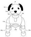
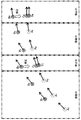
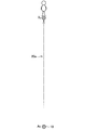
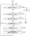
- FIG. 1 is a schematic front view of an autonomous mobile body 10 according to an embodiment of the present disclosure. It is a schematic left side view of autonomous mobile object 10 concerning the embodiment. It is the block diagram which showed the example of the function structure of the autonomous mobile body 10 which concerns on the embodiment. It is a figure showing an example of decision of a stop position concerning the embodiment. It is a figure showing an example of decision of a stop position concerning the embodiment. It is the figure which showed schematically the flow of the function of the self-position estimation part 156 which concerns on the embodiment. It is the figure which showed the difference of two types of self-position estimation methods concerning the embodiment. It is the figure which showed an example of switching of the self-position estimation method which concerns on the embodiment. It is the flow chart which showed a part of flow of processing concerning the embodiment.
- a plurality of components having substantially the same functional configuration may be distinguished by attaching different alphabets to the same reference numerals.
- a plurality of components having substantially the same functional configuration are distinguished as the internal sensor unit 172a and the internal sensor unit 172b as necessary.
- the internal sensor unit 172 is simply referred to as the internal sensor unit 172.
- the present disclosure can be implemented in various forms, as described in detail in “2. Detailed Description of the Embodiments” as an example. First, an example of the appearance configuration of the autonomous mobile body 10 according to the present embodiment will be described with reference to FIGS. 1A and 1B.
- the autonomous mobile body 10 is an example of an information processing apparatus according to the present disclosure.
- the autonomous mobile body 10 may be a device (machine) which can autonomously move using electrical and / or magnetic action.
- the autonomous mobile body 10 may be, for example, a robot (for example, a pet robot or the like) capable of autonomously moving (for example, walking or the like) on the ground.
- the autonomous mobile body 10 is a machine (device) that can operate autonomously using electrical and / or magnetic action or other general mobile body devices. I hope there is.
- the autonomous mobile body 10 may be another type of robot (for example, a humanoid robot or a drone), a vehicle (for example, a vehicle, a ship, an aircraft or the like), various industrial machines, or a toy .
- the autonomous mobile body 10 When acting (moving), the autonomous mobile body 10 can act while estimating its own position.
- the self position of the autonomous mobile body 10 can indicate the absolute position of the autonomous mobile body 10 in the real space.
- the self position may indicate the posture of the autonomous mobile body 10 in the real space.
- FIG. 1A is a schematic front view of the autonomous mobile body 10.
- FIG. 1B is a schematic left side view of the autonomous mobile body 10.
- the autonomous mobile body 10 may have a head 100, a body 102, and a movement mechanism 180.
- the autonomous mobile body 10 has a plurality of joints inside one or more of the head 100, the body 102, and the moving mechanism 180. Furthermore, an actuator is disposed inside each of the plurality of joints, and by driving these actuators under the control of a control unit 150 described later, each of the plurality of joints is set to a predetermined value. It can rotate around its axis.
- the autonomous mobile body 10 can realize the desired motion.
- a neck joint may be disposed between the head 100 and the body 102 so that the head 100 can rotate about a predetermined axis with respect to the body 102.
- a hip joint may be disposed between the individual legs 180 and the body 102 so that the individual legs 180 can rotate about a predetermined axis with respect to the body 102.
- the autonomous mobile body 10 is an internal sensor unit 172 configured to sense internal field information of the autonomous mobile body 10, and an external sensor configured to sense external world information of the autonomous mobile body 10. And a unit 174.
- the internal sensor unit 172 is an example of a first sensor unit according to the present disclosure.
- the external world sensor unit 174 is an example of a second sensor unit according to the present disclosure.
- the internal sensor unit 172 may be configured to sense (or measure) internal information at predetermined intervals.
- the internal world information may be information indicating an internal state of the autonomous mobile body 10.
- the inside information includes the velocity of the autonomous mobile body 10, the acceleration of the autonomous mobile body 10, the relative position of the autonomous mobile body 10, or the angular velocity of the autonomous mobile body 10.
- the internal field information may include the rotation angle of each joint in the autonomous mobile body 10 or the rotation speed of each joint.
- the internal sensor unit 172 includes a three-axis acceleration sensor, a three-axis gyro sensor, an encoder, and / or a wheel encoder.
- a three-axis acceleration sensor In the example shown in FIGS. 1A and 1B, one or more three-axis acceleration sensors and one or more three-axis gyro sensors may be disposed inside the head 100 and the body 102, respectively.
- an encoder may be disposed at each joint of the autonomous mobile body 10. Thereby, the rotation angle and the rotation speed of each joint can be sensed.
- the translational movement component of the autonomous mobile body 10 based on the sensing value by the encoder disposed at each joint of the autonomous mobile body 10 and the shape of the autonomous mobile body 10. And an attitude component about the yaw axis can be calculated. Furthermore, the posture component around the pitch axis and the posture around the roll axis of the autonomous mobile body 10 based on the sensing results by the three-axis gyro sensor and the three-axis acceleration sensor (IMU: Inertial Measurement Unit) contained in the internal sensor section 172. The components can be calculated.
- IMU Inertial Measurement Unit
- the external world sensor unit 174 is configured to sense external world information of the autonomous mobile body 10.
- the external world information may be information on the environment around the autonomous mobile body 10.
- the external world information may be a captured image around the autonomous mobile body 10, a distance from the autonomous mobile body 10 to each other object, a sound around the autonomous mobile body 10, geomagnetism around the autonomous mobile body 10, and / Alternatively, it may include radio wave conditions for wireless communication around the autonomous mobile body 10 or the like.
- the external sensor unit 174 may be a camera (such as a front camera 174a or a fisheye camera 174f), a depth sensor 174b (such as a ToF (Time of Flight) sensor or a stereo camera), or a person.
- the sensor 174 c, the distance sensor 174 d, and / or the microphone 174 e may be included.
- the fisheye camera 174f may capture an image of, for example, a hemispherical space around the fisheye camera 174f.
- the external environment sensor unit 174 is a communication for communication in accordance with a predetermined communication standard such as LIDAR (Light Detection And Ranging), a magnetic sensor, and / or, for example, Bluetooth (registered trademark) or Wi-Fi (registered trademark).
- a predetermined communication standard such as LIDAR (Light Detection And Ranging), a magnetic sensor, and / or, for example, Bluetooth (registered trademark) or Wi-Fi (registered trademark).
- An interface may be included.
- the external world sensor unit 174 may include, for example, a receiver that receives positioning signals from positioning satellites such as GPS (Global Positioning System) and GLONASS (Global Navigation Satellite System).
- the moving mechanism 180 is a mechanism for moving the autonomous mobile body 10.
- the moving mechanism 180 may be configured to include a plurality of legs (eg, two legs, four legs, etc.) for walking.
- the number of legs is not particularly limited, and may be an arbitrary number.
- the moving mechanism 180 may be configured to include a plurality of wheels, or may be configured to include an endless track mechanism such as Caterpillar (registered trademark), for example.
- the movement mechanism 180 has one or more actuators.
- the one or more actuators are driven based on the power supplied from the power supply unit (not shown) in the autonomous mobile body 10 and the control signal supplied from the motion control unit 158 described later.
- the autonomous mobile body 10 can move.
- the estimation method of the self-position desired for the autonomous mobile body 10 may differ depending on whether the autonomous mobile body 10 is moving or stopping. For example, during movement, it is desirable that the self position can be continuously obtained (estimated) from the viewpoint of the ability to follow the trajectory to be moved. In addition, during movement, it is desirable for the self-position estimation method to have a lower calculation load factor (for example, CPU (Central Processing Unit) load factor) of the autonomous mobile body 10.
- CPU Central Processing Unit
- the autonomous mobile unit 10 according to the present embodiment uses the continuous self position estimation using the sensing result by the internal sensor unit 172 and the sensing result by the external sensor unit 174 when estimating the self position. It is determined based on whether or not the state of the autonomous mobile body 10 is in the stop state, which one of the discrete self position estimation is to be used. For this reason, in the scene where the autonomous mobile body 10 repeats the stop state and the movement state, it is possible to estimate the self position more appropriately.
- continuous self-position estimation is an example of a first estimation method according to the present disclosure.
- discrete self position estimation is an example of a second estimation method according to the present disclosure. The contents of this embodiment will be sequentially described in detail below.
- FIG. 2 is a block diagram showing an example of a functional configuration of the autonomous mobile body 10.
- the autonomous mobile body 10 includes a control unit 150, a communication unit 170, an internal sensor unit 172, an external sensor unit 174, a storage unit 176, and a moving mechanism 180.
- description is abbreviate
- Control unit 150 may be configured to include, for example, a processing circuit such as a CPU, a graphics processing unit (GPU), and / or a nueral network processing unit (NPU).
- the control unit 150 centrally controls the operation of the autonomous mobile body 10. Further, as shown in FIG. 2, the control unit 150 includes an action planning unit 152, a state determination unit 154, a self position estimation unit 156, and a motion control unit 158.
- the action planning unit 152 is based on, for example, the sensing result of the inside information by the inside sensor unit 172, the sensing result of the outside information by the outside sensor unit 174, or the operation information of the user received via the communication unit 170. Plan the action of the autonomous mobile body 10.
- the action planning unit 152 plans on the change of the state of the autonomous mobile body 10 between the moving state and the stop state.
- the action planning unit 152 plans a stop condition for changing the state of the autonomous mobile body 10 from the moving state to the stop state.
- the action planning unit 152 plans the stop condition so that the state of the autonomous mobile body 10 is sequentially changed from the move state to the stop state. obtain.
- prescribed distance may be changed, for example in real time according to the state of the ground in which the autonomous mobile body 10 is moving.
- the behavior planning unit 152 acquires the internal world information acquired at the relevant timing each time the internal world sensor unit 172 acquires the sensing result of the internal world information.
- the state of the ground in motion may be sequentially identified based on the sensing result of and the value of the continuous movement distance may be sequentially changed according to the identified state of the ground.
- the state of the ground may include, for example, the slipperiness of the ground, the degree of unevenness the ground has, or the degree of inclination of the ground.
- the action planning unit 152 may make the value of the continuous movement distance smaller than the standard value.
- the behavior planning unit 152 may make the value of the continuous movement distance smaller than the standard value.
- the behavior planning unit 152 may make the value of the continuous movement distance smaller than the standard value.
- the behavior planning unit 152 may make the value of the continuous movement distance smaller than the standard value.
- the action planning unit 152 may set the autonomous mobile object 10 at any place (position) in the area captured in at least one of the plurality of key frames stored in the position / feature DB 178 described later.
- the stop condition may be planned such that the state of is changed from the move state to the stop state.
- key frames captured in advance in each of a plurality of places in the real space may be stored in association with position information of the places.
- the action planning unit 152 plans the stop condition so that the state of the autonomous mobile body 10 is sequentially changed from the move state to the stop state. May be
- the action planning unit 152 may use the stop condition so that the state of the autonomous mobile body 10 is changed from the moving state to the stop state using any two or more combinations of the three types of planning methods described above. You may plan.
- the action planning unit 152 can plan the movement route of the autonomous mobile body 10 according to the destination of the autonomous mobile body 10 and the self position estimated by the self position estimation unit 156 described later. . For example, before the autonomous mobile body 10 starts moving (in other words, when the autonomous mobile body 10 is located at the start point), the action plan unit 152 determines the start point and the destination of the autonomous mobile body 10 And planning the movement route of the autonomous mobile body based on the predetermined route determination method.
- the action planning unit 152 determines the self position estimated by the self position estimation unit 156 at the timing and the purpose of the autonomous mobile body 10 It is also possible to replan the traveling route of the autonomously moving body after the timing based on the ground and the predetermined route determination method.
- the predetermined route determination method may be a method of planning a global movement route to the destination.
- the predetermined route determination method is a method using a graph search algorithm such as an A * (A-star) search algorithm.
- FIG. 3A shows an example in which the start point of the autonomous mobile body 10 is “A0” and the destination of the autonomous mobile body 10 is set to “Xb”.
- the action planning unit 152 first uses the autonomous mobile body (at the start time) based on the start point (A0), the destination (Xb), and the predetermined route determination method described above. Plan ten moving routes 20a.
- the action planning unit 152 plans, for example, that the movement of a predetermined distance (“d” in the example illustrated in FIG. 3A) is completed as the stop condition.
- the action planning unit 152 may plan each stop condition until reaching the destination as the same condition or, every time it stops once, sequentially plans the contents of the next stop condition. May be
- the autonomous mobile body 10 stops at a place (“place Aa” in the example shown in FIG. 3A) which has moved by the distance d based on the planned travel route 20a and the stop condition.
- the action planning unit 152 executes the drawing based on the self position (place Aa) estimated by the self position estimation unit 156 described later, the destination (Xb), and the predetermined route determination method at the timing.
- the movement path 20b of the autonomous mobile body 10 after the said timing is replanned. Thereafter, the above process may be repeated until the autonomous mobile body 10 reaches the destination Xb.
- the state determination unit 154 determines whether the current state of the autonomous mobile body 10 is in the moving state or in the stopped state. For example, when it is specified based on the sensing result by the internal sensor unit 172 that the speed of the autonomous mobile body 10 continues to be equal to or less than a predetermined threshold for a predetermined time or more, the state determination unit 154 It is determined that the state of the mobile object 10 has been changed from the movement state to the stop state. Alternatively, when the stop condition planned by the action planning unit 152 is satisfied while the state of the autonomous mobile body 10 up to the latest is the moving state, the state determination portion 154 causes the state of the autonomous mobile body 10 to move. It may be determined that the state has been changed to the stop state.
- the self position estimation unit 156 estimates the self position of the autonomous mobile body 10 based on the determination result by the state determination unit 154.
- FIG. 4 is a diagram schematically showing the flow of functions of the self-position estimation unit 156 according to the present embodiment.
- the self-position estimation unit 156 uses discrete self-position estimation using the sensing result by the internal sensor unit 172 and discrete self-monitoring using the sensing result by the external sensor unit 174. It is determined based on the determination result by the state determination unit 154 which of the position estimation is to be used. For example, while the state determination unit 154 determines that the state of the autonomous mobile body 10 is not the stop state (that is, while it is determined that the state is the moving state), the self position estimation unit 156 It is decided to estimate the self position using the self self position estimation.
- the self position estimation unit 156 estimates the self position using the discrete self position estimation. decide. That is, when the state of the autonomous mobile body 10 changes from the moving state to the stopped state, the self position estimation unit 156 estimates the self position from the continuous self position estimation to the discrete self position estimation. Switch the way. In addition, when the state of the autonomous mobile body 10 changes from the stop state to the movement state, the self position estimation unit 156 estimates the self position from the discrete self position estimation to the continuous self position estimation. Switch the way.
- FIG. 5 is an explanatory view showing the difference between the continuous self-position estimation and the discrete self-position estimation.
- the continuous self position estimation estimates the self position of the autonomous mobile body 10 by integrating sensing results of internal information by the internal sensor unit 172 at each sensing timing up to the present time It can be a way to For example, as illustrated in FIG. 5, the inner sensor unit 172 may be configured by one or more physical quantities (for example, the velocity of the autonomous mobile 10, the acceleration of the autonomous mobile 10, the relative position of the autonomous mobile 10, or the autonomous mobile The acceleration of the body 10 or the like may be configured to be sensed (or measured) at each of the predetermined cycles described above.
- the continuous self-position estimation is performed by integrating the sensing results of the physical quantities of these types by the internal sensor unit 172 for each predetermined period, to obtain the self-position of the autonomous mobile body 10 (for example, It may be a method of estimating the absolute position and attitude of the mobile object 10 at each predetermined period.
- At least one encoder (which is an example of the internal sensor unit 172) can be disposed inside each joint in the autonomous mobile body 10.
- continuous self position estimation refers to the angle of each joint sensed at each predetermined cycle by the encoder in each joint, and, for example, the geometric shape of the autonomous mobile body 10 stored in the storage unit 176
- a method may be used to estimate the self-position of the autonomous mobile body 10 for each of the predetermined cycles, using existing forward dynamics calculation (for example, dead reckoning or odometry), using the above information.
- the said discrete self-position estimation estimates the self-position of the autonomous mobile body 10 by using the sensing result of the external world information by the external world sensor part 174 in one sensing timing. It can be. For example, as shown in FIG. 5, the discrete self-position estimation uses the sensing result of the external world information by the external world sensor unit 174 at one sensing timing to determine the absolute position and posture of the autonomous mobile body 10. It may be a method of calculating directly and estimating the calculation result as the self position of the autonomous mobile body 10.
- the discrete self position estimation is performed first by an image captured at a timing at which the autonomous mobile body 10 is stopped by an imaging unit (for example, a fisheye camera etc.) included in the external world sensor unit 174, a position / feature DB 178
- the method may be such that each of a plurality of key frames stored in is compared with each other, and then the self position is estimated using the position information associated with the key frame in which the result of the comparison satisfies the predetermined condition. .
- the self position estimation unit 156 matches the image captured by the imaging unit at the timing with each of the plurality of key frames ( Check) Next, the self position estimation unit 156 identifies the key frame with the best matching result. Then, the self position estimation unit 156 estimates the self position of the autonomous mobile body 10 based on the specified key frame, the matching result between the captured image and the position information associated with the specified key frame. May be
- the discrete self position estimation is not limited to the method of matching the captured image by the imaging unit (for example, matching of feature points of the image).
- the discrete self position estimation may be a method of estimating the self position by matching point cloud data acquired in advance with a sensing result by a depth sensor, LIDAR or the like.
- the continuous self-position estimation is a method of integrating sensing results of internal field information
- a cumulative error usually occurs according to the movement of the autonomous mobile body 10. For example, if the autonomous mobile body 10 estimates its own position using only the continuous self-position estimation, the cumulative error may gradually increase as it continues to move based on the estimated self-position. . Therefore, the amount of deviation between the estimated own position and the true position information of the autonomous mobile body 10 may also gradually increase.
- the self-position estimation unit 156 estimates self using the continuous self-position estimation up to the timing.
- the position may be corrected based on the self-position estimation result using the discrete self-position estimation. For example, as shown in FIG. 4, every time the self-position estimation unit 156 estimates self-position using the discrete self-position estimation, it estimates using the continuous self-position estimation until the timing.
- the above-mentioned correction is performed by discarding the self-position which has been performed and adopting the self-position estimated using the discrete self-position estimation at the timing as the self-position at the timing.
- the absolute position and orientation of the autonomous mobile body 10 can be calculated with high accuracy. Therefore, by performing the above-mentioned correction, the accumulated error based on the continuous self position estimation can be eliminated each time.
- FIG. 6 is a diagram showing an example of switching of the self-position estimation method while the autonomous mobile body 10 moves to the destination.
- A indicates the target position (true value) of the autonomous mobile body 10 at each timing on the movement route of the autonomous mobile body 10.
- B has shown the self-position (actual value) estimated using the said continuous self-position estimation in each said timing, respectively.
- C has shown the self-position (actual value) estimated at the said timing for every timing when the autonomous mobile body 10 used the said discrete self-position estimation.
- “D” indicates the target position (true value) of the autonomous mobile unit 10 at each timing indicated by “C” on the movement route of the autonomous mobile unit 10.
- the autonomous mobile body 10 estimates its own position using the continuous self-position estimation, it is continuously based on a previously planned movement route from the start point (A0). It can move.
- the amount of displacement (cumulative error) from the moving path increases. Go.
- the self-position estimation unit 156 switches the self-position estimation method from the continuous self-position estimation to the discrete self-position estimation.
- the self position estimation unit 156 first estimates the self position using the sensing result of the external world information by the external world sensor unit 174 at the timing and the discrete self position estimation.
- the self-position estimation unit 156 estimates the self-position estimated (ie, "C3" shown in FIG. 6) immediately before using the continuous self-position estimation (ie, FIG. 6). Correct the self position by adopting it instead of “B3” shown in. Thus, the accumulated error up to the timing is eliminated.
- the autonomous mobile body 10 resumes movement based on a previously planned travel route, the autonomous mobile body 10 moves to the destination while switching the method of estimating the self position as described above.
- Motion control unit 158 controls movement (such as movement) of the autonomous mobile body 10 based on the action plan planned by the action planning unit 152. For example, the movement control unit 158 moves so that the autonomous moving body 10 moves based on the latest movement route planned by the action planning unit 152 and the immediately preceding self position estimated by the self position estimation unit 156.
- the mechanism 180 is controlled.
- the motion control unit 158 causes the state of the autonomous mobile body 10 to stop from the moving state at the timing when the stop condition planned by the action plan unit 152 is satisfied.
- the moving mechanism 180 is controlled to change to
- the motion control unit 158 controls the moving mechanism 180 to start moving at the start point A0. Furthermore, the motion control unit 158 controls the moving mechanism 180 so as to stop the movement at the timing when the stop condition planned by the action planning unit 152 is satisfied (that is, the timing at which the movement by the distance "d" is performed).
- the communication unit 170 may be configured to include, for example, a communication interface such as a network card or an antenna.
- the communication unit 170 transmits / receives information to / from an external device via a network such as the Internet or a public network, for example.
- the communication unit 170 receives user operation information from an external device.
- the storage unit 176 may be configured to include, for example, storage devices such as a memory (RAM (Random Access Memory), ROM (Read Only Memory), etc.) and an HDD (Hard Disk Drive).
- the storage unit 176 stores, for example, various data such as the position / feature DB 178 and various software.
- FIG. 7 and FIG. 8 are flowcharts each showing a part of the flow of processing according to the present embodiment.
- the autonomous mobile body 10 is located at the start point and travels to the destination.
- the completion of the movement of the predetermined distance is determined as the stop condition.
- the action planning unit 152 of the autonomous mobile body 10 detects the position of the start point, the positional information of the destination, and the predetermined route determination method of the autonomous mobile body 10. Plan a movement route (S101).
- the motion control unit 158 controls the moving mechanism 180 so that the autonomous moving body 10 starts moving and moves based on the moving route planned in S101 (S103).
- the autonomous mobile body 10 repeats the following processing of S107 to S113.
- the autonomous mobile body 10 reaches the destination (S105: Yes)
- the flow of the process ends.
- the control unit 150 of the autonomous mobile body 10 determines whether the autonomous mobile body 10 has moved by the predetermined distance. In addition, when the autonomous mobile body 10 has already moved the predetermined distance at least once, the control unit 150 determines whether the autonomous mobile body 10 has moved by the predetermined distance from the timing of stopping immediately before. It determines (S107).
- the self-position estimation unit 156 determines whether a predetermined period corresponding to the continuous self-position estimation has elapsed. Determine if For example, when the predetermined cycle has already passed at least one time, the self-position estimation unit 156 determines whether the predetermined cycle has passed since the timing when the predetermined cycle has passed immediately before (S109). ). If it is determined that the predetermined cycle has not elapsed (S109: No), the autonomous mobile body 10 performs the process of S105 and thereafter again.
- the inner sensor portion 172 senses inner information of the autonomous mobile body 10 (S111). Then, the self-position estimation unit 156 estimates the self-position of the autonomous mobile body 10 by using the continuous self-position estimation (that is, integrating the sensing results of the internal information up to the present time) (S113) ).
- the autonomous mobile body 10 performs the processing of S105 and subsequent steps again.
- the outside world sensor unit 174 senses the outside world information of the autonomous mobile body 10 (S123).
- the self position estimation unit 156 estimates the self position by performing the discrete self position estimation using the external world information sensed in S123 (S125).
- the self-position estimation unit 156 corrects the self-position estimated using the continuous self-position estimation immediately before the timing based on the self-position estimated in S125 (S127).
- the action planning unit 152 replans the movement route of the autonomous mobile object 10 based on the self position estimated in S125, the position information of the destination, and the predetermined route determination method (S129).
- the motion control unit 158 controls the moving mechanism 180 so that the autonomous mobile body 10 resumes movement and moves based on the movement route replanned in S129 (S131).
- the autonomous mobile body 10 performs the processing of S105 and subsequent steps again.
- control unit 150 determines whether the autonomous mobile body 10 has moved by the predetermined distance in S107 has been described, but the present embodiment is not limited to this example.
- the control unit 150 may determine whether or not the autonomous mobile body 10 has moved continuously for a predetermined time. In this case, when the autonomous mobile body 10 continuously moves for a predetermined time (S107: Yes), the control unit 150 can perform the processing of S121 and subsequent steps. On the other hand, while the time in which the autonomous mobile body 10 has moved continuously is less than the predetermined time (S107: No), the control unit 150 can perform the processing of S109 and thereafter.
- the autonomous moving body 10 when the autonomous mobile object 10 according to the present embodiment estimates its own position, the autonomous moving body 10 continuously estimates its own position using the sensing result by the internal sensor unit 172, and the external sensor unit 174 It is determined based on whether or not the state of the autonomous mobile body 10 is in the stop state, which of the discrete self position estimation using the sensing result is to be used. For this reason, in the scene where the autonomous mobile body 10 repeats the stop state and the movement state, the self position can be estimated more appropriately.
- the autonomous mobile body 10 performs the self position every predetermined period using the continuous self position estimation.
- the autonomous mobile body 10 estimates the self position using the discrete self position estimation. Thereby, the accumulated error generated by the continuous self-position estimation can be periodically corrected by the discrete self-position estimation.
- the accuracy of the obtainable sensor value may usually be low even if a sensor (for example, GPS etc.) capable of grasping the absolute position and attitude is used.
- the autonomous mobile body 10 is likely to be unable to specify the absolute position and attitude. Since the autonomous mobile body 10 uses the discrete self-position estimation as described above instead of using such a sensor, even when moving indoors, an accurate self-position can be identified. .
- the autonomous mobile body 10 since the problem is less likely to occur indoors when the autonomous mobile body 10 stops periodically, for example, compared with the outdoors such as a road, the autonomous mobile body 10 periodically performs the discrete self-position estimation. It can be used.
- FIG. 9 is a diagram showing the difference between the movement state and the stop state.
- trajectory tracking is required, and the CPU load factor may be high.
- the load factor of the CPU becomes high.
- the CPU load factor may be low.
- the autonomous mobile body 10 since the autonomous mobile body 10 according to the present embodiment switches the estimation method of the self position as described above, it is possible to continuously acquire the self position by using the continuous self position estimation during movement. it can. Therefore, the autonomous mobile body 10 can easily follow the planned trajectory.
- the discrete self position estimation is used during stoppage, sensing results with higher accuracy can be acquired by the external world sensor unit 174, for example, blurring hardly occurs in a captured image by the imaging unit. Therefore, the estimation accuracy of the self position based on the discrete self position estimation can be improved. In addition, the estimation result of the self position by the said discrete self position estimation may become discontinuous (discrete). However, since the autonomous mobile body 10 uses the discrete self-position estimation during the stop, there is no particular problem.
- FIG. 10 is another diagram showing the difference between the continuous self-position estimation according to the present embodiment and the discrete self-position estimation.
- the discrete self-position estimation needs to handle a large amount of data, such as an image and point cloud data, for example. Therefore, as shown in FIG. 10, the discrete self-position estimation usually has a higher CPU load factor than the continuous self-position estimation.
- the autonomous mobile body 10 uses the discrete self position estimation while stopped (the CPU load factor associated with the action control is low), two processing loads of the self position estimation and the action control Balance can be optimized.
- Application Example 1 First, Application Example 1 will be described.
- the autonomous mobile body 10 tracks a predetermined mobile body (for example, a person) movable in a certain room in the room.
- a predetermined mobile body for example, a person
- the predetermined mobile body is a "person”
- a place within a predetermined distance from the place where the person is located is set as the destination of the autonomous mobile body 10.
- Action Planner 152 The action planning unit 152 according to the application example 1 first uses the external world information sensed by the external world sensor unit 174 at the timing when the state of the autonomous mobile body 10 is changed from the moving state to the stopped state. Identify the place where the person is located at the timing. Next, the action planning unit 152 redetermines the destination of the autonomous mobile body 10 according to the place where the person is located at the timing. The action planning unit 152 then performs autonomous movement after the timing based on the self position estimated using the discrete self position estimation at the timing and the destination redetermined at the timing. Replan the movement path of the body 10.
- the action planning unit 152 first determines the image captured by the external sensor unit 174 at that timing. By performing the recognition process, the location where the person to be tracked is located is identified. Next, the action planning unit 152 determines the destination “Xa” of the autonomous mobile body 10 according to the place where the target person is located. Then, the action planning unit 152 plans the moving route 20a of the autonomous mobile body 10 based on the position information of the start point "A0", the position information of the destination "Xa”, and the predetermined route determination method. Thereafter, the autonomous mobile body 10 starts moving on the basis of the moving path 20a.
- FIG. 11B is a diagram showing an example of the route plan of the autonomous mobile body 10 at the timing when the stop condition (for example, completion of the movement of the predetermined distance) is satisfied after the timing shown in FIG. 11A.
- the external sensor unit 174 of the autonomous mobile body 10 performs the predetermined recognition processing on the image captured at the timing. , And newly specify the place where the person of interest is located.
- the action planning unit 152 redetermines the destination of the autonomous mobile body 10 to “Xb” (in place of “Xa”) according to the place where the newly identified subject person is located.
- the action planning unit 152 causes the self position estimated by the above-mentioned discrete self position estimation at the timing (“Aa” in the example shown in FIG. 11B) and the position of the redetermined destination “Xb”.
- the movement route 20b of the autonomous mobile body 10 is replanned based on the information and the predetermined route determination method. Thereafter, the autonomous mobile body 10 resumes movement based on the replanned movement route 20b.
- FIGS. 12 and 13 are flowcharts each showing a part of the flow of processing according to Application Example 1.
- the autonomous mobile body 10 is located at the start point and travels to a place (destination) where a person to be tracked is located will be described.
- the completion of the movement of the predetermined distance is determined as the stop condition.
- the external world sensor unit 174 of the autonomous mobile body 10 senses external world information (S201).
- the action planning unit 152 identifies a place where the person of interest is located by recognizing a person to be tracked using the outside world information (captured image etc.) sensed in S201 (S203).
- the action planning unit 152 determines a position near the place identified in S203 as a destination. Then, the action planning unit 152 plans the moving route of the autonomous mobile body 10 based on the position information of the start point, the position information of the determined destination, and the predetermined route determination method (S205).
- the motion control unit 158 controls the moving mechanism 180 so that the autonomous moving body 10 starts moving and moves based on the moving route planned in S203 (S207).
- S209: Yes the flow of the process ends.
- the autonomous mobile body 10 repeats the processing of S211 to S217.
- S211 to S217 shown in FIG. 12 are substantially the same as S107 to S113 shown in FIG.
- the action planning unit 152 recognizes the person to be tracked by using the external world information (such as a captured image) sensed in S223, so that the person of the object is at the current position. Specify the place to be (S 229).
- the action planning unit 152 redetermines a position near the place identified in S229 as a destination. Then, the action planning unit 152 replans the movement route of the autonomous mobile object 10 based on the self position estimated in S225, the position information of the redetermined destination, and the predetermined route determination method (S231). ).
- Action Planner 152 The action planning unit 152 according to the application example 2 selects one of the plurality of key frames stored in the position / feature DB 178 when the self position of the autonomous mobile body 10 is estimated using the discrete self position estimation. , Any location in the area being imaged in one key frame used for self-position estimation at the relevant timing, based on the final destination of the autonomous mobile body 10 (ie, It can be determined as the next intermediate destination).
- the action planning unit 152 first performs position information of the start point "A0", position information of the final destination "Xb", and a predetermined route. Based on the determination method (for example, A * search algorithm etc.), the (global) movement path 20 of the autonomous mobile body 10 as shown in FIG. 14B is planned. Furthermore, the action planning unit 152 sets, for example, the planned movement route 20 to any position in the image of the corresponding room captured by the external world sensor unit 174 (for example, the fisheye camera 174f) at the start point “A0”. The next intermediate destination (“Xa” in the example shown in FIG. 14B) is determined based on that. Thereafter, the autonomous mobile body 10 can move from the start point “A0” to the next intermediate destination “Xa”.
- the determination method for example, A * search algorithm etc.
- the autonomous mobile body 10 can move to the final destination “Xb” by repeating the above process.
- FIGS. 15 to 17 are flowcharts each showing a part of the flow of processing according to Application Example 2.
- the autonomous mobile body 10 is located at the start point and travels to the final destination.
- the completion of the movement of the predetermined distance is determined as the stop condition.
- the action planning unit 152 of the autonomous mobile body 10 uses the autonomous mobile body 10 based on the position information of the start point, the position information of the final destination, and the predetermined route determination method.
- the (global) movement route is planned (S301).
- the outside world sensor unit 174 senses outside world information, for example, imaging a surrounding space (S303).
- the behavior planning unit 152 matches the plurality of key frames stored in the position / feature DB 178 with the captured image captured in S303, thereby the autonomously moving body 10 among the plurality of key frames. Identify the key frame that contains the current position of (ie, the starting point). Then, the action planning unit 152 sets the next intermediate destination (that is, the next intermediate destination) based on the movement route planned in S301 to any place in the area captured in the specified key frame. It decides as (S305).
- the action planning unit 152 plans a local movement route based on the position information of the start point and the position information of the next intermediate destination determined in S305 (S307).
- the motion control unit 158 controls the moving mechanism 180 so that the autonomous moving body 10 starts moving and moves based on the moving route planned in S307 (S309).
- the autonomous mobile body 10 repeats the following processing of S313 to S321. Specifically, first, the control unit 150 of the autonomous mobile body 10 determines whether the autonomous mobile body 10 has reached the next intermediate destination (S313). If the autonomous mobile body 10 has arrived at the next intermediate destination (S313: Yes), the control unit 150 performs the processing of S331 and later described later. When the autonomous mobile body 10 does not reach the next intermediate destination (S313: No), the autonomous mobile body 10 performs the same processing as S107 to S113 shown in FIG. 7 (S315 to S321).
- the action planning unit 152 performs S 343 and later described later. Do the processing.
- the action plan unit 152 stores a plurality of the position / feature DB 178.
- any location within the area being imaged in one keyframe used for the discrete self-position estimation in the nearest S335 is based on the global movement route planned in S301. Is determined as the next intermediate destination (S341).
- the action planning unit 152 replans the local movement route based on the self position estimated in S335, the position information of the next intermediate destination, and the predetermined route determination method (S343).
- the information processing apparatus is, for example, a server, a general-purpose PC (Personal Computer), a tablet terminal, a game machine, a mobile phone such as a smartphone, a wearable device such as an HMD (Head Mounted Display) or a smart watch, or It may be a car navigation device or the like.
- a server a general-purpose PC (Personal Computer)
- a tablet terminal a game machine
- a mobile phone such as a smartphone
- a wearable device such as an HMD (Head Mounted Display) or a smart watch
- It may be a car navigation device or the like.
- the information processing apparatus can control the behavior of the autonomous mobile body 10 through, for example, the above-described network. For example, the information processing apparatus stops the state of the autonomous mobile body 10 whether the autonomous mobile body 10 is to estimate the self position using either the continuous self position estimation or the discrete self position estimation. It determines based on whether it is a state.
- each step in each process flow described above may not necessarily be processed in the order described.
- each step may be processed in an appropriate order.
- each step may be processed partially in parallel or individually instead of being processed chronologically.
- some of the described steps may be omitted or additional steps may be added.
- hardware such as a CPU, a ROM, and a RAM has the same function as each component (for example, the control unit 150 or the like) of the autonomous mobile body 10 according to each embodiment described above. It is also possible to provide a computer program for making it work. There is also provided a storage medium having the computer program recorded thereon.
- An information processing apparatus comprising: (2) The first estimation method is a method of estimating a self-position of the autonomously moving body by integrating sensing results of the inside information by the first sensor unit at each sensing timing up to the present time. The information processing apparatus according to (1).
- the second estimation method is a method of estimating the self-position of the autonomously moving body by using the sensing result of the external world information by the second sensor unit at one sensing timing.
- the information processing apparatus according to claim 1.
- the first sensor unit is configured to sense the internal field information at predetermined intervals, The first estimation method integrates the sensing result of the internal field information by the first sensor unit at each of the sensing timings up to the present, for each of the predetermined periods, thereby generating the self for each of the predetermined periods.
- the information processing apparatus according to (3) which is a method of estimating a position.
- the second sensor unit includes an imaging unit.
- a storage unit that associates and stores a key frame captured in advance in each of a plurality of locations in the real space and position information of the locations.
- the second estimation method collates a captured image by the imaging unit at the one sensing timing with a plurality of key frames stored in the storage unit, and also selects one of the plurality of key frames.
- the information processing apparatus according to (4), wherein the self-position of the autonomously moving body is estimated based on position information associated with a key frame in which a result of the matching satisfies a predetermined condition. (6) While the state of the autonomous mobile body is not in the stopped state, the control unit determines that the autonomous mobile body is to estimate the self position using the first estimation method.
- the control unit determines that the autonomous mobile body is to estimate the self position using the second estimation method.
- the information processing apparatus according to any one of (5) to (5).
- the control unit causes the autonomous mobile body to estimate the self-position for each predetermined cycle using the first estimation method, At each timing when the state of the autonomous mobile body is changed to the stop state, the control unit causes the autonomous mobile body to sequentially estimate the self-position using the second estimation method at the timing.
- a storage unit that associates and stores a key frame captured in advance in each of a plurality of locations in the real space and position information of the locations.
- the control unit is configured to stop the state of the autonomously moving body from the movement state at any place in an area captured in at least one of the plurality of key frames stored in the storage unit.
- the information processing apparatus according to (8), wherein the stop condition is planned to be changed to a state.
- the control unit determines the self position estimated using the second estimation method at the timing and the autonomous movement at each timing when the state of the autonomous moving body is changed from the moving state to the stopped state.
- the information processing apparatus according to (9), wherein the moving route of the autonomously moving body after the timing is replanned based on the predetermined destination of the body.
- the predetermined destination is a place within a predetermined distance from a place where a predetermined movable body movable in the real space is located,
- the control unit uses the external world information sensed at the timing by the second sensor unit at the timing. Identify the place where the predetermined mobile body is located, Redetermining the predetermined destination at the timing according to the position where the predetermined moving body is positioned at the timing, and Based on the self-position estimated using the second estimation method at the timing and the predetermined destination re-determined at the timing, the movement route of the autonomous mobile body after the timing is The information processing apparatus according to (10), which replans.
- the predetermined destination is a predetermined place where the autonomous mobile body is moving to the final destination of the autonomous mobile body
- the second sensor unit includes an imaging unit.
- the second estimation method collates a captured image by the imaging unit at the one sensing timing with a plurality of key frames stored in the storage unit, and also selects one of the plurality of key frames.
- a method of estimating the self position of the autonomous mobile object based on position information associated with a key frame in which the result of the matching satisfies a predetermined condition When the self-position of the autonomous mobile body is estimated using the second estimation method, the control unit is further configured to capture an image of the result of the matching at the timing in a key frame that satisfies a predetermined condition.
- the information processing apparatus which redetermines any place in an area as the predetermined destination.
- the control unit is further configured to capture an image of the result of the matching at the timing in a key frame that satisfies a predetermined condition.
- the information processing apparatus according to (12), wherein any location in the area is redetermined as the predetermined destination based on the final destination of the autonomous mobile body.
- the control unit further plans the stop condition such that the state of the autonomous mobile body is sequentially changed from the mobile state to the stop state whenever the autonomous mobile body continuously moves by a predetermined distance.
- the information processing apparatus according to any one of (10) to (13).
- the control unit is configured to obtain the inside of the acquired at the timing when the sensing result of the inside information is acquired by the first sensor unit.
- the autonomous mobile body sequentially identifies the state of the moving ground based on the sensing result of the field information, and The information processing apparatus according to (14), wherein the length of the predetermined distance is changed according to the identified ground condition.
- the information processing apparatus according to (15), wherein the state of the ground includes slipperiness of the ground, a degree of unevenness which the ground has, or a degree of inclination of the ground.
- the control unit is further configured to cause the autonomous moving body to change from the moving state to the stopping state at timing when the stopping condition is satisfied while the state of the autonomous moving body is the moving state.
- the information processing apparatus according to any one of (10) to (16), which controls movement of a moving body.
- the information processing apparatus is the autonomous mobile body, The information processing apparatus according to (17), wherein the control unit further estimates a self position of the information processing apparatus using the determined estimation method.
Landscapes
- Engineering & Computer Science (AREA)
- Radar, Positioning & Navigation (AREA)
- Remote Sensing (AREA)
- Physics & Mathematics (AREA)
- General Physics & Mathematics (AREA)
- Automation & Control Theory (AREA)
- Aviation & Aerospace Engineering (AREA)
- Multimedia (AREA)
- Robotics (AREA)
- Mechanical Engineering (AREA)
- Computer Vision & Pattern Recognition (AREA)
- Electromagnetism (AREA)
- Human Computer Interaction (AREA)
- Theoretical Computer Science (AREA)
- Control Of Position, Course, Altitude, Or Attitude Of Moving Bodies (AREA)
Abstract
[Problème] Fournir un dispositif de traitement d'informations, un procédé de traitement d'informations et un programme pouvant déterminer une méthode pour estimer l'emplacement propre d'un objet autonome en mouvement avec adaptation à l'état dudit objet. [Solution] L'invention concerne un dispositif de traitement d'informations muni d'une unité de commande qui, lorsqu'un objet autonome en mouvement estime son propre emplacement, détermine laquelle d'une première méthode d'estimation et d'une seconde méthode d'estimation est utilisée pour l'objet autonome en mouvement selon que l'état de l'objet autonome en mouvement est un état d'arrêt ou non. La première méthode d'estimation utilise un résultat de détection produit par une première unité de détection configurée pour détecter des informations internes sur l'objet autonome en mouvement, et la seconde méthode d'estimation utilise un résultat de détection produit par une seconde unité de détection configurée pour détecter des informations externes sur l'objet autonome en mouvement.
Priority Applications (1)
| Application Number | Priority Date | Filing Date | Title |
|---|---|---|---|
| US16/959,513 US11926038B2 (en) | 2018-01-10 | 2018-10-22 | Information processing apparatus and information processing method |
Applications Claiming Priority (2)
| Application Number | Priority Date | Filing Date | Title |
|---|---|---|---|
| JP2018-002002 | 2018-01-10 | ||
| JP2018002002 | 2018-01-10 |
Publications (1)
| Publication Number | Publication Date |
|---|---|
| WO2019138640A1 true WO2019138640A1 (fr) | 2019-07-18 |
Family
ID=67218272
Family Applications (1)
| Application Number | Title | Priority Date | Filing Date |
|---|---|---|---|
| PCT/JP2018/039117 Ceased WO2019138640A1 (fr) | 2018-01-10 | 2018-10-22 | Dispositif de traitement d'informations, procédé de traitement d'informations, et programme |
Country Status (2)
| Country | Link |
|---|---|
| US (1) | US11926038B2 (fr) |
| WO (1) | WO2019138640A1 (fr) |
Cited By (3)
| Publication number | Priority date | Publication date | Assignee | Title |
|---|---|---|---|---|
| JP2021188956A (ja) * | 2020-05-27 | 2021-12-13 | 鹿島建設株式会社 | 断面形状取得方法及び断面形状取得装置 |
| JP2022542241A (ja) * | 2019-07-23 | 2022-09-30 | トヨタ リサーチ インスティテュート,インコーポレイティド | ロボット装置からの視覚的出力を補強するシステム及び方法 |
| WO2026069532A1 (fr) * | 2024-09-26 | 2026-04-02 | 本田技研工業株式会社 | Dispositif de commande de corps mobile, procédé de commande de corps mobile et programme |
Families Citing this family (2)
| Publication number | Priority date | Publication date | Assignee | Title |
|---|---|---|---|---|
| JP7353747B2 (ja) * | 2018-01-12 | 2023-10-02 | キヤノン株式会社 | 情報処理装置、システム、方法、およびプログラム |
| CN113074724B (zh) * | 2021-03-26 | 2023-05-02 | 歌尔股份有限公司 | 运动时间计算方法、装置、设备及计算机可读存储介质 |
Citations (7)
| Publication number | Priority date | Publication date | Assignee | Title |
|---|---|---|---|---|
| JPH01134606A (ja) * | 1987-11-20 | 1989-05-26 | Sanyo Electric Co Ltd | 自立走行作業車 |
| JPH06161550A (ja) * | 1992-11-27 | 1994-06-07 | Daifuku Co Ltd | 移動車走行制御装置 |
| JP2005182834A (ja) * | 2003-12-23 | 2005-07-07 | Samsung Electronics Co Ltd | 移動体の回転移動量利用方法とその装置、及びコンピュータプログラムを保存するコンピュータ読取り可能な記録媒体 |
| JP2009193097A (ja) * | 2008-02-12 | 2009-08-27 | Yaskawa Electric Corp | 移動ロボットの制御装置および移動ロボットシステム |
| JP2011209203A (ja) * | 2010-03-30 | 2011-10-20 | Sony Corp | 自己位置推定装置および自己位置推定方法 |
| JP2015036840A (ja) * | 2013-08-12 | 2015-02-23 | ヤマハ発動機株式会社 | 自律走行車両、自律走行車両の制御システム及び自律走行車両の制御方法 |
| JP2017107425A (ja) * | 2015-12-10 | 2017-06-15 | カシオ計算機株式会社 | 自律移動装置、自律移動方法及びプログラム |
Family Cites Families (10)
| Publication number | Priority date | Publication date | Assignee | Title |
|---|---|---|---|---|
| EP2135498B1 (fr) * | 2008-06-20 | 2012-06-20 | AGROCOM GmbH & Co. Agrarsystem KG | Procédé de navigation d'un véhicule agricole et véhicule agricole |
| KR101152720B1 (ko) * | 2009-10-30 | 2012-06-18 | 주식회사 유진로봇 | 이동 로봇의 슬립 감지 장치 및 방법 |
| JP5560978B2 (ja) * | 2010-07-13 | 2014-07-30 | 村田機械株式会社 | 自律移動体 |
| AU2011305154B2 (en) * | 2010-09-24 | 2015-02-05 | Irobot Corporation | Systems and methods for VSLAM optimization |
| WO2013185102A1 (fr) * | 2012-06-08 | 2013-12-12 | Irobot Corporation | Estimation de déplacement d'un tapis à l'aide de capteurs différentiels ou de mesures visuelles |
| KR101725060B1 (ko) * | 2014-06-17 | 2017-04-10 | 주식회사 유진로봇 | 그래디언트 기반 특징점을 이용한 이동 로봇의 위치를 인식하기 위한 장치 및 그 방법 |
| US10042361B2 (en) * | 2015-12-07 | 2018-08-07 | Beijing Unistrong Science & Technology Co., Ltd. | System and method for terrestrial vehicle navigation |
| US10989542B2 (en) * | 2016-03-11 | 2021-04-27 | Kaarta, Inc. | Aligning measured signal data with slam localization data and uses thereof |
| US11313684B2 (en) * | 2016-03-28 | 2022-04-26 | Sri International | Collaborative navigation and mapping |
| EP3519768B1 (fr) * | 2016-10-03 | 2025-04-30 | AgJunction LLC | Utilisation de capteurs optiques pour résoudre des problèmes de cap de véhicule |
-
2018
- 2018-10-22 WO PCT/JP2018/039117 patent/WO2019138640A1/fr not_active Ceased
- 2018-10-22 US US16/959,513 patent/US11926038B2/en active Active
Patent Citations (7)
| Publication number | Priority date | Publication date | Assignee | Title |
|---|---|---|---|---|
| JPH01134606A (ja) * | 1987-11-20 | 1989-05-26 | Sanyo Electric Co Ltd | 自立走行作業車 |
| JPH06161550A (ja) * | 1992-11-27 | 1994-06-07 | Daifuku Co Ltd | 移動車走行制御装置 |
| JP2005182834A (ja) * | 2003-12-23 | 2005-07-07 | Samsung Electronics Co Ltd | 移動体の回転移動量利用方法とその装置、及びコンピュータプログラムを保存するコンピュータ読取り可能な記録媒体 |
| JP2009193097A (ja) * | 2008-02-12 | 2009-08-27 | Yaskawa Electric Corp | 移動ロボットの制御装置および移動ロボットシステム |
| JP2011209203A (ja) * | 2010-03-30 | 2011-10-20 | Sony Corp | 自己位置推定装置および自己位置推定方法 |
| JP2015036840A (ja) * | 2013-08-12 | 2015-02-23 | ヤマハ発動機株式会社 | 自律走行車両、自律走行車両の制御システム及び自律走行車両の制御方法 |
| JP2017107425A (ja) * | 2015-12-10 | 2017-06-15 | カシオ計算機株式会社 | 自律移動装置、自律移動方法及びプログラム |
Cited By (7)
| Publication number | Priority date | Publication date | Assignee | Title |
|---|---|---|---|---|
| JP2022542241A (ja) * | 2019-07-23 | 2022-09-30 | トヨタ リサーチ インスティテュート,インコーポレイティド | ロボット装置からの視覚的出力を補強するシステム及び方法 |
| JP7581320B2 (ja) | 2019-07-23 | 2024-11-12 | トヨタ リサーチ インスティテュート,インコーポレイティド | ロボット装置からの視覚的出力を補強するシステム及び方法 |
| JP2021188956A (ja) * | 2020-05-27 | 2021-12-13 | 鹿島建設株式会社 | 断面形状取得方法及び断面形状取得装置 |
| JP2023171501A (ja) * | 2020-05-27 | 2023-12-01 | 鹿島建設株式会社 | 無人移動体 |
| JP7407071B2 (ja) | 2020-05-27 | 2023-12-28 | 鹿島建設株式会社 | 断面形状取得方法及び断面形状取得装置 |
| JP7618761B2 (ja) | 2020-05-27 | 2025-01-21 | 鹿島建設株式会社 | 無人移動体 |
| WO2026069532A1 (fr) * | 2024-09-26 | 2026-04-02 | 本田技研工業株式会社 | Dispositif de commande de corps mobile, procédé de commande de corps mobile et programme |
Also Published As
| Publication number | Publication date |
|---|---|
| US20210053232A1 (en) | 2021-02-25 |
| US11926038B2 (en) | 2024-03-12 |
Similar Documents
| Publication | Publication Date | Title |
|---|---|---|
| US11340610B2 (en) | Autonomous target following method and device | |
| WO2019138640A1 (fr) | Dispositif de traitement d'informations, procédé de traitement d'informations, et programme | |
| CN106682572B (zh) | 目标跟踪方法、系统和第一电子设备 | |
| US11921508B2 (en) | Systems and methods for ground plane estimation | |
| EP3850581B1 (fr) | Systèmes et procédés d'estimation d'échelle de vslam à l'aide d'un capteur de flux optique sur un dispositif robotique | |
| KR102895133B1 (ko) | 군집 로봇을 이용하여 사용자의 위치를 추적하는 방법, 태그장치 및 이를 구현하는 로봇 | |
| US20260009649A1 (en) | Mobile body, method of controlling mobile body, and program | |
| WO2019031168A1 (fr) | Corps mobile et procédé de commande de corps mobile | |
| JP7750246B2 (ja) | 情報処理装置、情報処理システム、および方法、並びにプログラム | |
| EP4139765B1 (fr) | Procédés, dispositifs et systèmes pour faciliter les opérations de robots mobiles | |
| KR102837653B1 (ko) | 대면적의 공간에서 로컬 영역별로 위치를 추정하는 방법 및 이를 구현하는 로봇과 클라우드 서버 | |
| WO2020008754A1 (fr) | Dispositif de traitement d'informations, procédé d'estimation d'instant optimal, procédé d'estimation de position propre et support d'enregistrement dans lequel un programme est enregistré | |
| KR102368734B1 (ko) | 드론 및 드론 제어 방법 | |
| US10386839B2 (en) | Mobile robot that emulates pedestrian walking behavior | |
| KR20230078647A (ko) | 이동 지원 장치 및 이동 지원 제공 방법 | |
| CN113724323A (zh) | 一种地图构建方法、装置及设备 | |
| US12422850B2 (en) | Information processing apparatus and information processing method to manage path information of a mobile robot | |
| Etzion et al. | MoRPI: Mobile robot pure inertial navigation | |
| JP6825715B2 (ja) | 移動車両 | |
| US20210107143A1 (en) | Recording medium, information processing apparatus, and information processing method | |
| JP5171394B2 (ja) | 移動型ロボット | |
| JP7484915B2 (ja) | 移動体制御装置および移動体制御方法 | |
| CN113932814B (zh) | 一种基于多模态地图的协同定位方法 | |
| CN117622210A (zh) | 运行用于高度自动化行驶的车辆的方法和设备和用于高度自动化行驶的车辆 | |
| CN116300613A (zh) | 一种融合uwb和imu的智能跟随服务机器人及其控制方法、装置和存储介质 |
Legal Events
| Date | Code | Title | Description |
|---|---|---|---|
| 121 | Ep: the epo has been informed by wipo that ep was designated in this application |
Ref document number: 18899904 Country of ref document: EP Kind code of ref document: A1 |
|
| NENP | Non-entry into the national phase |
Ref country code: DE |
|
| 122 | Ep: pct application non-entry in european phase |
Ref document number: 18899904 Country of ref document: EP Kind code of ref document: A1 |
|
| NENP | Non-entry into the national phase |
Ref country code: JP |