EP3520936A1 - Lame pour outil de dénudage et de coupe - Google Patents
Lame pour outil de dénudage et de coupe Download PDFInfo
- Publication number
- EP3520936A1 EP3520936A1 EP18155222.5A EP18155222A EP3520936A1 EP 3520936 A1 EP3520936 A1 EP 3520936A1 EP 18155222 A EP18155222 A EP 18155222A EP 3520936 A1 EP3520936 A1 EP 3520936A1
- Authority
- EP
- European Patent Office
- Prior art keywords
- blade
- base body
- insert
- cutting edge
- insert blade
- Prior art date
- Legal status (The legal status is an assumption and is not a legal conclusion. Google has not performed a legal analysis and makes no representation as to the accuracy of the status listed.)
- Granted
Links
Images

Classifications
-
- B—PERFORMING OPERATIONS; TRANSPORTING
- B26—HAND CUTTING TOOLS; CUTTING; SEVERING
- B26D—CUTTING; DETAILS COMMON TO MACHINES FOR PERFORATING, PUNCHING, CUTTING-OUT, STAMPING-OUT OR SEVERING
- B26D3/00—Cutting work characterised by the nature of the cut made; Apparatus therefor
- B26D3/28—Splitting layers from work; Mutually separating layers by cutting
-
- B—PERFORMING OPERATIONS; TRANSPORTING
- B23—MACHINE TOOLS; METAL-WORKING NOT OTHERWISE PROVIDED FOR
- B23B—TURNING; BORING
- B23B5/00—Turning-machines or devices specially adapted for particular work; Accessories specially adapted therefor
- B23B5/16—Turning-machines or devices specially adapted for particular work; Accessories specially adapted therefor for bevelling, chamfering, or deburring the ends of bars or tubes
- B23B5/161—Devices attached to the workpiece
- B23B5/162—Devices attached to the workpiece with an internal clamping device
-
- B—PERFORMING OPERATIONS; TRANSPORTING
- B26—HAND CUTTING TOOLS; CUTTING; SEVERING
- B26D—CUTTING; DETAILS COMMON TO MACHINES FOR PERFORATING, PUNCHING, CUTTING-OUT, STAMPING-OUT OR SEVERING
- B26D1/00—Cutting through work characterised by the nature or movement of the cutting member or particular materials not otherwise provided for; Apparatus or machines therefor; Cutting members therefor
- B26D1/0006—Cutting members therefor
-
- B—PERFORMING OPERATIONS; TRANSPORTING
- B26—HAND CUTTING TOOLS; CUTTING; SEVERING
- B26D—CUTTING; DETAILS COMMON TO MACHINES FOR PERFORATING, PUNCHING, CUTTING-OUT, STAMPING-OUT OR SEVERING
- B26D1/00—Cutting through work characterised by the nature or movement of the cutting member or particular materials not otherwise provided for; Apparatus or machines therefor; Cutting members therefor
- B26D1/01—Cutting through work characterised by the nature or movement of the cutting member or particular materials not otherwise provided for; Apparatus or machines therefor; Cutting members therefor involving a cutting member which does not travel with the work
- B26D1/04—Cutting through work characterised by the nature or movement of the cutting member or particular materials not otherwise provided for; Apparatus or machines therefor; Cutting members therefor involving a cutting member which does not travel with the work having a linearly-movable cutting member
-
- B—PERFORMING OPERATIONS; TRANSPORTING
- B26—HAND CUTTING TOOLS; CUTTING; SEVERING
- B26D—CUTTING; DETAILS COMMON TO MACHINES FOR PERFORATING, PUNCHING, CUTTING-OUT, STAMPING-OUT OR SEVERING
- B26D3/00—Cutting work characterised by the nature of the cut made; Apparatus therefor
- B26D3/001—Cutting tubes longitudinally
-
- B—PERFORMING OPERATIONS; TRANSPORTING
- B26—HAND CUTTING TOOLS; CUTTING; SEVERING
- B26D—CUTTING; DETAILS COMMON TO MACHINES FOR PERFORATING, PUNCHING, CUTTING-OUT, STAMPING-OUT OR SEVERING
- B26D3/00—Cutting work characterised by the nature of the cut made; Apparatus therefor
- B26D3/28—Splitting layers from work; Mutually separating layers by cutting
- B26D3/282—Splitting layers from work; Mutually separating layers by cutting by peeling-off
-
- B—PERFORMING OPERATIONS; TRANSPORTING
- B23—MACHINE TOOLS; METAL-WORKING NOT OTHERWISE PROVIDED FOR
- B23B—TURNING; BORING
- B23B2220/00—Details of turning, boring or drilling processes
- B23B2220/40—Peeling
-
- B—PERFORMING OPERATIONS; TRANSPORTING
- B26—HAND CUTTING TOOLS; CUTTING; SEVERING
- B26D—CUTTING; DETAILS COMMON TO MACHINES FOR PERFORATING, PUNCHING, CUTTING-OUT, STAMPING-OUT OR SEVERING
- B26D1/00—Cutting through work characterised by the nature or movement of the cutting member or particular materials not otherwise provided for; Apparatus or machines therefor; Cutting members therefor
- B26D1/0006—Cutting members therefor
- B26D2001/0053—Cutting members therefor having a special cutting edge section or blade section
-
- B—PERFORMING OPERATIONS; TRANSPORTING
- B26—HAND CUTTING TOOLS; CUTTING; SEVERING
- B26D—CUTTING; DETAILS COMMON TO MACHINES FOR PERFORATING, PUNCHING, CUTTING-OUT, STAMPING-OUT OR SEVERING
- B26D1/00—Cutting through work characterised by the nature or movement of the cutting member or particular materials not otherwise provided for; Apparatus or machines therefor; Cutting members therefor
- B26D1/0006—Cutting members therefor
- B26D2001/006—Cutting members therefor the cutting blade having a special shape, e.g. a special outline, serrations
Definitions
- the invention relates to a blade for a stripping and peeling tool for stripping and peeling a pre-insulated tube comprising a base body, wherein the base body is formed as an elongated, thin plate, wherein the plate is convex and the apex of the convex curvature along the length of the Plate extends, wherein on a longitudinal edge of the plate or the base body, a cutting edge is arranged, which serves to release the insulating layer from the inner tube and an insert blade.
- Abmanteletti are also known from the prior art for stripping a metal tube provided with a protective layer.
- the EP 1 118 405 A1 discloses such a device.
- both devices mentioned above are not suitable for stripping and peeling a pre-insulated pipe, which usually includes a slightly thicker foam insulation, which is to be separated from the inner tube and then to rework the outer casing tube surface of the inner tube so that the surface is suitable for a Welding is suitable.
- pre-insulated pipelines are used where it requires a good isolation of the medium from the ambient conditions, for example.
- an insulating layer is preferably arranged from foamed plastic, wherein the insulating layer is surrounded by an outer skin or an outer tube, which preferably made of plastic but also of a metal and serves to protect the insulation layer.
- Such pipes must be stripped at their ends and the medium pipe to be peeled on the outer surface to be connected to fittings or other pipes can, as the connection is made via the medium pipe to ensure the tightness.
- the EP 3 213 890 A1 discloses a tool with which a stripping and peeling a pre-insulated pipe is possible.
- the blade used allows both the stripping by separating the insulation layer, as well as the peeling of the outer surface of the inner tube.
- a disadvantage of the above-mentioned embodiment, however, is that the blade or the blades arranged thereon are rigidly aligned and can not adapt to the outer lateral surface of the inner tube.
- the insert blade is formed as a separate part and the blade includes an axis, wherein the axis of storage of the insert blade in the base body and preferably protrudes through the insert blade, wherein the insert blade has a cutting edge and the insert blade so in Basic body is arranged so that the cutting edge of the insert blade runs parallel to the cutting edge on the base body.
- the inventive blade for stripping and peeling a pre-insulated pipe includes a base body, wherein the base body is formed as an elongated, thin plate.
- the plate has over the entire length a convex configuration, that is, the plate has on its inner side, which is aligned towards the inner tube, a curvature preferably to a radius as well as on the outside, the two curvatures preferably radii preferably run concentrically. Due to the convex configuration of the plate, the apex of the curvature preferably extends along the length of the plate or the Grundgropers radius.
- a cutting edge is arranged, wherein the cutting edge serves to release the insulating layer from the inner tube.
- the blade is rotated on one side or in the one direction of rotation and the subsequent peeling is preferably carried out by means of a rotation in the opposite direction, wherein the peeling can also take place during the rotation or the release of the insulating layer.
- the blade includes an insert blade which is formed as a separate part and is arranged in the base body.
- the insert blade is mounted in the base body by means of an axle, which projects through the insert blade, whereby the insert blade has the opportunity to move up and down and is guided on the left and right of the main body.
- the cutting blade disposed on the insert blade is aligned parallel to the cutting edge on the base body, wherein it is aligned in the opposite or the same direction as the cutting edge on the base body.
- the base body has a recess in which the insert blade is arranged.
- the insert blade is optimally guided and aligned.
- the recess in the main body is formed continuously and is completely enclosed by the main body. This means that the recess penetrates the base body or the plate completely and is surrounded on all sides by the base body, so that the base frame framed the recess. This has the advantage that the body is stable in itself and has no noses or corners that stand separately and get caught with the insulation layer.
- the blade has a spring element which serves to press the insert blade. Since the insert blade is mounted on the axle, the insert blade has the ability to move up and down to adapt to the outer surface of the inner tube. In order to exert a certain bias on the insert blade or to achieve a force to peel the outer lateral surface, the spring element presses down the insert blade or against the inner tube. The insulating layer which runs above the blade also exerts a contact pressure on the blade which serves for the peeling process.
- the invention is also distinguished by the fact that the base body has a thickness of only 1 to 4 mm, especially preferably 1.5 to 3 mm, thereby permitting piercing into the insulating layer. Moreover, it is advantageous if the base body has a bevel on the two longitudinal sides and preferably on the front side. The bevels on the long side allow the insulation a better sliding over the blade and the slope on the front side reduce the resistance when piercing the insulation layer.
- the insert blade has a gradation of the thickness or of different heights over the length of the insert blade.
- the inner surface of the insert blade facing the inner tube to be peeled has different heights. This serves to ensure that the cutting edge comes into contact with the outer lateral surface, even if the rear region or the Exceptional range of the insert blade when peeling first on the not yet peeled outer lateral surface moves, which still has a larger diameter than the finally peeled diameter. Due to the height differences ensures that the cutting edge or the peeling area of the insert blade can still engage sufficiently deep in the lateral surface to ablate material, since the cutting edge is higher than the rear portion of the blade serves as an exception and rests only on the outer surface if no deeper peeling is more desirable.
- the peeling area projects beyond the exceptional range between 0.2-0.8 mm, especially preferably 0.2-0.5 mm. In height on the inner surface of the insert blade.
- the insert blade has different areas on the inner surface, which preferably have different heights.
- the areas serve a different purpose as previously mentioned.
- the insert blade has, on the one hand, a peeling region on which the cutting edge is arranged and, on the other hand, at least one exception region, which is arranged behind the peeling region. At the height of the peeling area or the cutting edge dominates the exception area to a peel.
- a contact area is arranged on the insert blade, which is preferably arranged in front of the peeling area or in front of the cutting edge.
- the insert blade preferably in the front region has a support region for supporting the insert blade at the end of the peeling process or the unscrewing of the blade. This avoids that the cutting edge digs into the lateral surface at the end of the pipe, but rather that the peeling ends straight.
- a preferred embodiment is that the cutting edge on the base body and the cutting edge on the insert blade runs parallel to the tube axis of the pipe to be removed, this allows easy stripping and peeling with a tool in one clamping.
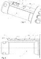
- FIG. 1 The drawing shows the blade 1 according to the invention in a corresponding tool for ablation and peeling of pre-insulated pipelines.
- the pipe end to be stripped is plugged and the blade 1 according to the invention is then screwed by a rotational movement in the insulating layer of the pre-insulated pipe.
- the ones shown here Fig. 1 and 2 show the blade 1 in the position in which it is completely immersed in the tube, in which case the tube is not shown to show the blade clearly visible.
- the blade 1 does not yet protrude beyond the mandrel 4 but rises slowly over the rotational movement in the position shown.
- the blade 1 includes a base body 2 which is preferably made of a metallic material.
- the main body 2 has a shape as an elongated, thin plate, which has a convex curvature.
- the convex curvature on the outside 5 is good in the 4 and 5 recognizable.
- the curvature 5, which is preferably formed as a radius, has the advantage that the separated insulating layer easily slides over the blade 1 as it continues to penetrate into the insulating layer as well as in the Unscrew the blade 1 during the peeling process.
- a convex curvature 6 is also arranged, which is also preferably formed as a radius, whereby the blade 1 and the base body 2 good on the outer surface of the inner tube applies and so good insulation and peeling can be done ,
- the vertex 7 of the convex curvature 5 extends parallel to the length of the main body 2 and the plate.
- a cutting edge 8 which serves for stripping or loosening the insulating layer of the outer lateral surface of the inner tube (not shown).
- the cutting edge 8 extends over the entire length of the basic body 2.
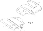
- the blade 1 includes an insert blade 3, which is formed as a separate part, which works well in Fig. 6 is recognizable.
- the insert blade 3 is arranged or mounted in the base body 2.
- the axis 9 protrudes through the insert blade 3 and thereby allows the insert blade 3 a pivotal movement down and up to adapt well to the outer surface of the inner tube during the peeling process.
- the insert blade 3 has a cutting edge 10, which serves for peeling the outer lateral surface of the inner tube.
- the insert blade 3 is arranged in the base body 2 such that the cutting edge 10 of the insert blade 3 runs parallel to the cutting edge 8 on the base body 3 and the cutting edge 10 of the inserting blade 3 is aligned in the opposite or the same direction of the cutting edge 8 on the base body 2.
- the oppositely disposed cutting edges 8, 10 are due to the fact that the stripping or separating the insulating layer from the inner tube in one direction of rotation and the subsequent peeling in the other direction of rotation, whereby the blade 1 is screwed out of the tube again.
- the peeling takes place during the stripping as during the same rotation process, consequently the screwing in.
- the main body 2 has a recess 11 in which the insert blade 3 is arranged.
- the recess 11 is formed continuously so that the inserted therein insert blade 3 protrudes and the outer surface of the Inner tube can contact.
- the recess 11 completely surrounded by the base body 2, that is, it is open on each side and thus completely framed by the base body 2, whereby the complete body 2 has good stability and rigidity as well as no protruding elements with could get caught up in isolation.
- the insert blade 3 is preferably additionally pressed down by means of a spring element 12, in addition to that the insulating layer also presses on the insert blade 3 while it slides during the peeling operation when unscrewing the blade over the base body 2.
- the insert blade 3 has on its inner surface 13, which faces the inner tube to be peeled a height gradation, this is good in Fig. 3 to recognize.
- the peeling area is designed to be higher than the exceptional area 15 lying behind or also the supporting area 19 lying in front. Since the inner tube is peeled during the unscrewing of the blade 1, the exceptional area 15 is above the unheated tube, which thus has a larger one Outer diameter has.
- the exception region 15 has a lower height than the peeling region 13.
- the inserting blade 3 in front of the peeling region 13 has a bearing region 19 which prevents the peeling region 14 or The cutting edge 10 digs into the tube at the end of the tube since there is no possibility of support through the exception region 15 since this is already outside the tube.
- Fig. 5 is clearly visible as the insert blade 3 is mounted on the axis 9 in the base body 2.
- the base body 2 has a stop on which limits the rotational movement of the insert blade 3 down, wherein the stop is not shown in the figures.
Landscapes
- Engineering & Computer Science (AREA)
- Mechanical Engineering (AREA)
- Life Sciences & Earth Sciences (AREA)
- Forests & Forestry (AREA)
- Knives (AREA)
- Removal Of Insulation Or Armoring From Wires Or Cables (AREA)
Priority Applications (6)
| Application Number | Priority Date | Filing Date | Title |
|---|---|---|---|
| DK18155222.5T DK3520936T3 (da) | 2018-02-06 | 2018-02-06 | Klinge til afisolerings- og skæreværktøj |
| ES18155222T ES2829567T3 (es) | 2018-02-06 | 2018-02-06 | Cuchilla para herramienta de retirada de aislante y corte |
| PT181552225T PT3520936T (pt) | 2018-02-06 | 2018-02-06 | Lâmina para uma ferramenta de descarnar e cortar |
| EP18155222.5A EP3520936B1 (fr) | 2018-02-06 | 2018-02-06 | Lame pour outil de dénudage et de coupe |
| CA3031104A CA3031104C (fr) | 2018-02-06 | 2019-01-22 | Lame d'outil de decapage et de coupe |
| US16/263,115 US10695929B2 (en) | 2018-02-06 | 2019-01-31 | Blade for a stripping and cutting tool |
Applications Claiming Priority (1)
| Application Number | Priority Date | Filing Date | Title |
|---|---|---|---|
| EP18155222.5A EP3520936B1 (fr) | 2018-02-06 | 2018-02-06 | Lame pour outil de dénudage et de coupe |
Publications (2)
| Publication Number | Publication Date |
|---|---|
| EP3520936A1 true EP3520936A1 (fr) | 2019-08-07 |
| EP3520936B1 EP3520936B1 (fr) | 2020-09-16 |
Family
ID=61167932
Family Applications (1)
| Application Number | Title | Priority Date | Filing Date |
|---|---|---|---|
| EP18155222.5A Active EP3520936B1 (fr) | 2018-02-06 | 2018-02-06 | Lame pour outil de dénudage et de coupe |
Country Status (6)
| Country | Link |
|---|---|
| US (1) | US10695929B2 (fr) |
| EP (1) | EP3520936B1 (fr) |
| CA (1) | CA3031104C (fr) |
| DK (1) | DK3520936T3 (fr) |
| ES (1) | ES2829567T3 (fr) |
| PT (1) | PT3520936T (fr) |
Families Citing this family (2)
| Publication number | Priority date | Publication date | Assignee | Title |
|---|---|---|---|---|
| CN114012806B (zh) * | 2021-11-04 | 2023-03-21 | 金豹科技(苏州)有限公司 | 一种方便存储杂质的金属氧化层无损去除治具 |
| JP7733586B2 (ja) * | 2022-01-21 | 2025-09-03 | 積水化学工業株式会社 | 合成樹脂管用スクレーパー |
Citations (4)
| Publication number | Priority date | Publication date | Assignee | Title |
|---|---|---|---|---|
| JPH0679501A (ja) | 1992-08-31 | 1994-03-22 | Osaka Gas Co Ltd | 管外周面切削工具 |
| EP1118405A1 (fr) | 1999-12-15 | 2001-07-25 | Mapress GmbH & Co. KG | Appareil de dénudage manuel de tubes |
| EP1787743A1 (fr) * | 2005-11-18 | 2007-05-23 | HDS Hydraulik GmbH & Co. KG | Outil de dénuder pour tuyaux et procédé pour dénuder la couche de revêtement des tuyaux renforcés |
| EP3213890A1 (fr) | 2016-03-01 | 2017-09-06 | Georg Fischer Rohrleitungssysteme AG | Outil de coupe et d'ecroutage |
Family Cites Families (13)
| Publication number | Priority date | Publication date | Assignee | Title |
|---|---|---|---|---|
| US2641944A (en) * | 1949-10-19 | 1953-06-16 | Aeroquip Corp | Hose covering stripping tool |
| US3171309A (en) * | 1962-11-19 | 1965-03-02 | Cloutier Alfred Joseph | Device for turning male ends on pipe |
| US3354762A (en) * | 1966-11-25 | 1967-11-28 | George D Wolff | Hose cover stripping tool |
| US3999452A (en) * | 1975-01-24 | 1976-12-28 | Gardner-Denver Company | Tool for preparing tube ends for welding |
| US3965570A (en) * | 1975-04-21 | 1976-06-29 | The Weatherhead Company | Hose skiving tool |
| FR2587251B1 (fr) * | 1985-09-19 | 1993-09-24 | Gaz De France | Procede et appareil pour gratter la surface exterieure d'un tube |
| SE500310C2 (sv) * | 1990-12-03 | 1994-05-30 | Sandvik Ab | Skär och verktyg för skalsvarvning |
| SE502261C2 (sv) * | 1991-03-04 | 1995-09-25 | Sandvik Ab | Verktyg för skalsvarvning försett med polygonala grovskär och färdigskär |
| US5979276A (en) * | 1998-02-17 | 1999-11-09 | Mertz, Inc. | Skiving apparatus and methods |
| GB2365811B (en) * | 2000-07-24 | 2004-01-14 | Uponor Ltd | Pipe preparing tool VI |
| US6698321B2 (en) * | 2001-03-14 | 2004-03-02 | Fritz Oswald | Pipe shaver |
| US6751869B2 (en) * | 2002-07-12 | 2004-06-22 | Patrick W. Paggeot | Skirted floor scraper blade |
| US8220371B2 (en) * | 2009-08-20 | 2012-07-17 | Oceaneering International, Inc. | Pipe turning tool |
-
2018
- 2018-02-06 DK DK18155222.5T patent/DK3520936T3/da active
- 2018-02-06 EP EP18155222.5A patent/EP3520936B1/fr active Active
- 2018-02-06 PT PT181552225T patent/PT3520936T/pt unknown
- 2018-02-06 ES ES18155222T patent/ES2829567T3/es active Active
-
2019
- 2019-01-22 CA CA3031104A patent/CA3031104C/fr active Active
- 2019-01-31 US US16/263,115 patent/US10695929B2/en active Active
Patent Citations (4)
| Publication number | Priority date | Publication date | Assignee | Title |
|---|---|---|---|---|
| JPH0679501A (ja) | 1992-08-31 | 1994-03-22 | Osaka Gas Co Ltd | 管外周面切削工具 |
| EP1118405A1 (fr) | 1999-12-15 | 2001-07-25 | Mapress GmbH & Co. KG | Appareil de dénudage manuel de tubes |
| EP1787743A1 (fr) * | 2005-11-18 | 2007-05-23 | HDS Hydraulik GmbH & Co. KG | Outil de dénuder pour tuyaux et procédé pour dénuder la couche de revêtement des tuyaux renforcés |
| EP3213890A1 (fr) | 2016-03-01 | 2017-09-06 | Georg Fischer Rohrleitungssysteme AG | Outil de coupe et d'ecroutage |
Also Published As
| Publication number | Publication date |
|---|---|
| EP3520936B1 (fr) | 2020-09-16 |
| DK3520936T3 (da) | 2020-10-26 |
| PT3520936T (pt) | 2020-10-09 |
| CA3031104A1 (fr) | 2019-08-06 |
| ES2829567T3 (es) | 2021-06-01 |
| US10695929B2 (en) | 2020-06-30 |
| US20190240855A1 (en) | 2019-08-08 |
| CA3031104C (fr) | 2026-03-03 |
Similar Documents
| Publication | Publication Date | Title |
|---|---|---|
| DE69214199T2 (de) | Verbinder für Koaxialkabel mit einem schraubenförmig gewellten Innenleiter | |
| EP2676750B1 (fr) | Dispositif de guidage d'appareils à écorcer | |
| EP0454615A1 (fr) | Pince pour couper des clous, des fils ou d'autres articles chirurgicaux similaires | |
| EP3520936B1 (fr) | Lame pour outil de dénudage et de coupe | |
| DE102014104474B4 (de) | Rohrabschneider | |
| DE1900741C3 (de) | Vorrichtung zur Formgebung konischer Metallrohre | |
| DE102019112363A1 (de) | Rohrschneider zum Schneiden eines Rundrohres und Verfahren zum Ablängen eines Rundrohres | |
| EP1459825A1 (fr) | Outil pour couper les boulons ou les tiges, notamment les tiges filetées | |
| EP3723928B1 (fr) | Dispositif de coupe pour couper des tubes ondulés à longueur et guidage des saillies dans un tel dispositif de coupe | |
| DE112016004295T5 (de) | Lagerdichtung und Ausziehwerkzeug | |
| DE102016120158B4 (de) | Vorrichtung zum Öffnen und Spalten von Kokosnüssen | |
| EP3784440B1 (fr) | Pince | |
| DE4327356C2 (de) | Vorrichtung zum Abisolieren von Litzenleitern | |
| DE2619909A1 (de) | Nussknacker | |
| EP1118405A1 (fr) | Appareil de dénudage manuel de tubes | |
| EP2487755A1 (fr) | Vis de serrage | |
| DE3139052A1 (de) | Vorrichtung zum aufbrechen von nuessen o.dgl. | |
| AT506634B1 (de) | Einrichtung zum einbringen einer öffnung in eine sprühdose | |
| DE2027862B2 (fr) | ||
| EP2077175B1 (fr) | Outil de séparation de tuyaux | |
| DE202020101249U1 (de) | Zerlegergeschoss | |
| DE840789C (de) | Kaltpressschweisswerkzeug mit einer streifenfoermigen ebenen Pressflaeche | |
| EP2468430B1 (fr) | Dispositif de traitement de tuyaux | |
| DE202011002628U1 (de) | Ananas-Schneider | |
| EP2878414A1 (fr) | Outil de perforation |
Legal Events
| Date | Code | Title | Description |
|---|---|---|---|
| PUAI | Public reference made under article 153(3) epc to a published international application that has entered the european phase |
Free format text: ORIGINAL CODE: 0009012 |
|
| STAA | Information on the status of an ep patent application or granted ep patent |
Free format text: STATUS: THE APPLICATION HAS BEEN PUBLISHED |
|
| AK | Designated contracting states |
Kind code of ref document: A1 Designated state(s): AL AT BE BG CH CY CZ DE DK EE ES FI FR GB GR HR HU IE IS IT LI LT LU LV MC MK MT NL NO PL PT RO RS SE SI SK SM TR |
|
| AX | Request for extension of the european patent |
Extension state: BA ME |
|
| STAA | Information on the status of an ep patent application or granted ep patent |
Free format text: STATUS: REQUEST FOR EXAMINATION WAS MADE |
|
| 17P | Request for examination filed |
Effective date: 20200128 |
|
| RBV | Designated contracting states (corrected) |
Designated state(s): AL AT BE BG CH CY CZ DE DK EE ES FI FR GB GR HR HU IE IS IT LI LT LU LV MC MK MT NL NO PL PT RO RS SE SI SK SM TR |
|
| REG | Reference to a national code |
Ref country code: DE Ref legal event code: R079 Ref document number: 502018002436 Country of ref document: DE Free format text: PREVIOUS MAIN CLASS: B23B0005160000 Ipc: B26D0003280000 |
|
| GRAP | Despatch of communication of intention to grant a patent |
Free format text: ORIGINAL CODE: EPIDOSNIGR1 |
|
| RIC1 | Information provided on ipc code assigned before grant |
Ipc: B26D 3/28 20060101AFI20200423BHEP |
|
| STAA | Information on the status of an ep patent application or granted ep patent |
Free format text: STATUS: GRANT OF PATENT IS INTENDED |
|
| INTG | Intention to grant announced |
Effective date: 20200528 |
|
| GRAS | Grant fee paid |
Free format text: ORIGINAL CODE: EPIDOSNIGR3 |
|
| GRAA | (expected) grant |
Free format text: ORIGINAL CODE: 0009210 |
|
| STAA | Information on the status of an ep patent application or granted ep patent |
Free format text: STATUS: THE PATENT HAS BEEN GRANTED |
|
| AK | Designated contracting states |
Kind code of ref document: B1 Designated state(s): AL AT BE BG CH CY CZ DE DK EE ES FI FR GB GR HR HU IE IS IT LI LT LU LV MC MK MT NL NO PL PT RO RS SE SI SK SM TR |
|
| REG | Reference to a national code |
Ref country code: GB Ref legal event code: FG4D Free format text: NOT ENGLISH |
|
| REG | Reference to a national code |
Ref country code: CH Ref legal event code: EP |
|
| REG | Reference to a national code |
Ref country code: DE Ref legal event code: R096 Ref document number: 502018002436 Country of ref document: DE |
|
| REG | Reference to a national code |
Ref country code: PT Ref legal event code: SC4A Ref document number: 3520936 Country of ref document: PT Date of ref document: 20201009 Kind code of ref document: T Free format text: AVAILABILITY OF NATIONAL TRANSLATION Effective date: 20201002 |
|
| REG | Reference to a national code |
Ref country code: IE Ref legal event code: FG4D Free format text: LANGUAGE OF EP DOCUMENT: GERMAN |
|
| REG | Reference to a national code |
Ref country code: AT Ref legal event code: REF Ref document number: 1313732 Country of ref document: AT Kind code of ref document: T Effective date: 20201015 |
|
| REG | Reference to a national code |
Ref country code: DK Ref legal event code: T3 Effective date: 20201020 |
|
| REG | Reference to a national code |
Ref country code: SE Ref legal event code: TRGR |
|
| REG | Reference to a national code |
Ref country code: FI Ref legal event code: FGE |
|
| REG | Reference to a national code |
Ref country code: NL Ref legal event code: FP |
|
| PG25 | Lapsed in a contracting state [announced via postgrant information from national office to epo] |
Ref country code: HR Free format text: LAPSE BECAUSE OF FAILURE TO SUBMIT A TRANSLATION OF THE DESCRIPTION OR TO PAY THE FEE WITHIN THE PRESCRIBED TIME-LIMIT Effective date: 20200916 Ref country code: BG Free format text: LAPSE BECAUSE OF FAILURE TO SUBMIT A TRANSLATION OF THE DESCRIPTION OR TO PAY THE FEE WITHIN THE PRESCRIBED TIME-LIMIT Effective date: 20201216 Ref country code: GR Free format text: LAPSE BECAUSE OF FAILURE TO SUBMIT A TRANSLATION OF THE DESCRIPTION OR TO PAY THE FEE WITHIN THE PRESCRIBED TIME-LIMIT Effective date: 20201217 Ref country code: NO Free format text: LAPSE BECAUSE OF FAILURE TO SUBMIT A TRANSLATION OF THE DESCRIPTION OR TO PAY THE FEE WITHIN THE PRESCRIBED TIME-LIMIT Effective date: 20201216 |
|
| PG25 | Lapsed in a contracting state [announced via postgrant information from national office to epo] |
Ref country code: LV Free format text: LAPSE BECAUSE OF FAILURE TO SUBMIT A TRANSLATION OF THE DESCRIPTION OR TO PAY THE FEE WITHIN THE PRESCRIBED TIME-LIMIT Effective date: 20200916 Ref country code: RS Free format text: LAPSE BECAUSE OF FAILURE TO SUBMIT A TRANSLATION OF THE DESCRIPTION OR TO PAY THE FEE WITHIN THE PRESCRIBED TIME-LIMIT Effective date: 20200916 |
|
| REG | Reference to a national code |
Ref country code: LT Ref legal event code: MG4D |
|
| PG25 | Lapsed in a contracting state [announced via postgrant information from national office to epo] |
Ref country code: CZ Free format text: LAPSE BECAUSE OF FAILURE TO SUBMIT A TRANSLATION OF THE DESCRIPTION OR TO PAY THE FEE WITHIN THE PRESCRIBED TIME-LIMIT Effective date: 20200916 Ref country code: RO Free format text: LAPSE BECAUSE OF FAILURE TO SUBMIT A TRANSLATION OF THE DESCRIPTION OR TO PAY THE FEE WITHIN THE PRESCRIBED TIME-LIMIT Effective date: 20200916 Ref country code: EE Free format text: LAPSE BECAUSE OF FAILURE TO SUBMIT A TRANSLATION OF THE DESCRIPTION OR TO PAY THE FEE WITHIN THE PRESCRIBED TIME-LIMIT Effective date: 20200916 Ref country code: LT Free format text: LAPSE BECAUSE OF FAILURE TO SUBMIT A TRANSLATION OF THE DESCRIPTION OR TO PAY THE FEE WITHIN THE PRESCRIBED TIME-LIMIT Effective date: 20200916 Ref country code: SM Free format text: LAPSE BECAUSE OF FAILURE TO SUBMIT A TRANSLATION OF THE DESCRIPTION OR TO PAY THE FEE WITHIN THE PRESCRIBED TIME-LIMIT Effective date: 20200916 |
|
| PG25 | Lapsed in a contracting state [announced via postgrant information from national office to epo] |
Ref country code: AL Free format text: LAPSE BECAUSE OF FAILURE TO SUBMIT A TRANSLATION OF THE DESCRIPTION OR TO PAY THE FEE WITHIN THE PRESCRIBED TIME-LIMIT Effective date: 20200916 Ref country code: IS Free format text: LAPSE BECAUSE OF FAILURE TO SUBMIT A TRANSLATION OF THE DESCRIPTION OR TO PAY THE FEE WITHIN THE PRESCRIBED TIME-LIMIT Effective date: 20210116 Ref country code: PL Free format text: LAPSE BECAUSE OF FAILURE TO SUBMIT A TRANSLATION OF THE DESCRIPTION OR TO PAY THE FEE WITHIN THE PRESCRIBED TIME-LIMIT Effective date: 20200916 |
|
| REG | Reference to a national code |
Ref country code: ES Ref legal event code: FG2A Ref document number: 2829567 Country of ref document: ES Kind code of ref document: T3 Effective date: 20210601 |
|
| REG | Reference to a national code |
Ref country code: DE Ref legal event code: R097 Ref document number: 502018002436 Country of ref document: DE |
|
| PG25 | Lapsed in a contracting state [announced via postgrant information from national office to epo] |
Ref country code: SK Free format text: LAPSE BECAUSE OF FAILURE TO SUBMIT A TRANSLATION OF THE DESCRIPTION OR TO PAY THE FEE WITHIN THE PRESCRIBED TIME-LIMIT Effective date: 20200916 |
|
| PLBE | No opposition filed within time limit |
Free format text: ORIGINAL CODE: 0009261 |
|
| STAA | Information on the status of an ep patent application or granted ep patent |
Free format text: STATUS: NO OPPOSITION FILED WITHIN TIME LIMIT |
|
| 26N | No opposition filed |
Effective date: 20210617 |
|
| PG25 | Lapsed in a contracting state [announced via postgrant information from national office to epo] |
Ref country code: SI Free format text: LAPSE BECAUSE OF FAILURE TO SUBMIT A TRANSLATION OF THE DESCRIPTION OR TO PAY THE FEE WITHIN THE PRESCRIBED TIME-LIMIT Effective date: 20200916 |
|
| PG25 | Lapsed in a contracting state [announced via postgrant information from national office to epo] |
Ref country code: MC Free format text: LAPSE BECAUSE OF FAILURE TO SUBMIT A TRANSLATION OF THE DESCRIPTION OR TO PAY THE FEE WITHIN THE PRESCRIBED TIME-LIMIT Effective date: 20200916 |
|
| REG | Reference to a national code |
Ref country code: BE Ref legal event code: MM Effective date: 20210228 |
|
| PG25 | Lapsed in a contracting state [announced via postgrant information from national office to epo] |
Ref country code: CH Free format text: LAPSE BECAUSE OF NON-PAYMENT OF DUE FEES Effective date: 20210228 Ref country code: LI Free format text: LAPSE BECAUSE OF NON-PAYMENT OF DUE FEES Effective date: 20210228 Ref country code: LU Free format text: LAPSE BECAUSE OF NON-PAYMENT OF DUE FEES Effective date: 20210206 |
|
| PG25 | Lapsed in a contracting state [announced via postgrant information from national office to epo] |
Ref country code: IE Free format text: LAPSE BECAUSE OF NON-PAYMENT OF DUE FEES Effective date: 20210206 |
|
| PG25 | Lapsed in a contracting state [announced via postgrant information from national office to epo] |
Ref country code: BE Free format text: LAPSE BECAUSE OF NON-PAYMENT OF DUE FEES Effective date: 20210228 |
|
| PG25 | Lapsed in a contracting state [announced via postgrant information from national office to epo] |
Ref country code: CY Free format text: LAPSE BECAUSE OF FAILURE TO SUBMIT A TRANSLATION OF THE DESCRIPTION OR TO PAY THE FEE WITHIN THE PRESCRIBED TIME-LIMIT Effective date: 20200916 |
|
| P01 | Opt-out of the competence of the unified patent court (upc) registered |
Effective date: 20230529 |
|
| PG25 | Lapsed in a contracting state [announced via postgrant information from national office to epo] |
Ref country code: HU Free format text: LAPSE BECAUSE OF FAILURE TO SUBMIT A TRANSLATION OF THE DESCRIPTION OR TO PAY THE FEE WITHIN THE PRESCRIBED TIME-LIMIT; INVALID AB INITIO Effective date: 20180206 |
|
| PG25 | Lapsed in a contracting state [announced via postgrant information from national office to epo] |
Ref country code: MK Free format text: LAPSE BECAUSE OF FAILURE TO SUBMIT A TRANSLATION OF THE DESCRIPTION OR TO PAY THE FEE WITHIN THE PRESCRIBED TIME-LIMIT Effective date: 20200916 |
|
| PG25 | Lapsed in a contracting state [announced via postgrant information from national office to epo] |
Ref country code: MT Free format text: LAPSE BECAUSE OF FAILURE TO SUBMIT A TRANSLATION OF THE DESCRIPTION OR TO PAY THE FEE WITHIN THE PRESCRIBED TIME-LIMIT Effective date: 20200916 |
|
| PGFP | Annual fee paid to national office [announced via postgrant information from national office to epo] |
Ref country code: ES Payment date: 20250331 Year of fee payment: 8 |
|
| PGFP | Annual fee paid to national office [announced via postgrant information from national office to epo] |
Ref country code: NL Payment date: 20260218 Year of fee payment: 9 |
|
| PGFP | Annual fee paid to national office [announced via postgrant information from national office to epo] |
Ref country code: SE Payment date: 20260218 Year of fee payment: 9 |
|
| PGFP | Annual fee paid to national office [announced via postgrant information from national office to epo] |
Ref country code: GB Payment date: 20260219 Year of fee payment: 9 |
|
| PGFP | Annual fee paid to national office [announced via postgrant information from national office to epo] |
Ref country code: DE Payment date: 20260218 Year of fee payment: 9 Ref country code: DK Payment date: 20260220 Year of fee payment: 9 |
|
| PGFP | Annual fee paid to national office [announced via postgrant information from national office to epo] |
Ref country code: AT Payment date: 20260219 Year of fee payment: 9 |
|
| PGFP | Annual fee paid to national office [announced via postgrant information from national office to epo] |
Ref country code: FI Payment date: 20260226 Year of fee payment: 9 Ref country code: IT Payment date: 20260224 Year of fee payment: 9 |
|
| PGFP | Annual fee paid to national office [announced via postgrant information from national office to epo] |
Ref country code: FR Payment date: 20260218 Year of fee payment: 9 |
|
| PGFP | Annual fee paid to national office [announced via postgrant information from national office to epo] |
Ref country code: TR Payment date: 20260202 Year of fee payment: 9 |
|
| PGFP | Annual fee paid to national office [announced via postgrant information from national office to epo] |
Ref country code: PT Payment date: 20260129 Year of fee payment: 9 |
|
| PGFP | Annual fee paid to national office [announced via postgrant information from national office to epo] |
Ref country code: PL Payment date: 20260130 Year of fee payment: 9 |