EP3521729A1 - Système de formation d'un cadre support pour plusieurs objets en forme de plaque et disposés sur une surface - Google Patents
Système de formation d'un cadre support pour plusieurs objets en forme de plaque et disposés sur une surface Download PDFInfo
- Publication number
- EP3521729A1 EP3521729A1 EP18155221.7A EP18155221A EP3521729A1 EP 3521729 A1 EP3521729 A1 EP 3521729A1 EP 18155221 A EP18155221 A EP 18155221A EP 3521729 A1 EP3521729 A1 EP 3521729A1
- Authority
- EP
- European Patent Office
- Prior art keywords
- carrier
- profile
- shaped
- plate
- web
- Prior art date
- Legal status (The legal status is an assumption and is not a legal conclusion. Google has not performed a legal analysis and makes no representation as to the accuracy of the status listed.)
- Granted
Links
Images






Classifications
-
- F—MECHANICAL ENGINEERING; LIGHTING; HEATING; WEAPONS; BLASTING
- F24—HEATING; RANGES; VENTILATING
- F24S—SOLAR HEAT COLLECTORS; SOLAR HEAT SYSTEMS
- F24S25/00—Arrangement of stationary mountings or supports for solar heat collector modules
- F24S25/60—Fixation means, e.g. fasteners, specially adapted for supporting solar heat collector modules
- F24S25/67—Fixation means, e.g. fasteners, specially adapted for supporting solar heat collector modules for coupling adjacent modules or their peripheral frames
-
- E—FIXED CONSTRUCTIONS
- E04—BUILDING
- E04D—ROOF COVERINGS; SKY-LIGHTS; GUTTERS; ROOF-WORKING TOOLS
- E04D13/00—Special arrangements or devices in connection with roof coverings; Protection against birds; Roof drainage ; Sky-lights
- E04D13/12—Devices or arrangements allowing walking on the roof or in the gutter
-
- F—MECHANICAL ENGINEERING; LIGHTING; HEATING; WEAPONS; BLASTING
- F24—HEATING; RANGES; VENTILATING
- F24S—SOLAR HEAT COLLECTORS; SOLAR HEAT SYSTEMS
- F24S25/00—Arrangement of stationary mountings or supports for solar heat collector modules
- F24S25/20—Peripheral frames for modules
-
- F—MECHANICAL ENGINEERING; LIGHTING; HEATING; WEAPONS; BLASTING
- F24—HEATING; RANGES; VENTILATING
- F24S—SOLAR HEAT COLLECTORS; SOLAR HEAT SYSTEMS
- F24S25/00—Arrangement of stationary mountings or supports for solar heat collector modules
- F24S25/30—Arrangement of stationary mountings or supports for solar heat collector modules using elongate rigid mounting elements extending substantially along the supporting surface, e.g. for covering buildings with solar heat collectors
- F24S25/33—Arrangement of stationary mountings or supports for solar heat collector modules using elongate rigid mounting elements extending substantially along the supporting surface, e.g. for covering buildings with solar heat collectors forming substantially planar assemblies, e.g. of coplanar or stacked profiles
-
- H—ELECTRICITY
- H02—GENERATION; CONVERSION OR DISTRIBUTION OF ELECTRIC POWER
- H02S—GENERATION OF ELECTRIC POWER BY CONVERSION OF INFRARED RADIATION, VISIBLE LIGHT OR ULTRAVIOLET LIGHT, e.g. USING PHOTOVOLTAIC [PV] MODULES
- H02S20/00—Supporting structures for PV modules
- H02S20/20—Supporting structures directly fixed to an immovable object
- H02S20/22—Supporting structures directly fixed to an immovable object specially adapted for buildings
- H02S20/23—Supporting structures directly fixed to an immovable object specially adapted for buildings specially adapted for roof structures
-
- F—MECHANICAL ENGINEERING; LIGHTING; HEATING; WEAPONS; BLASTING
- F24—HEATING; RANGES; VENTILATING
- F24S—SOLAR HEAT COLLECTORS; SOLAR HEAT SYSTEMS
- F24S20/00—Solar heat collectors specially adapted for particular uses or environments
- F24S2020/10—Solar modules layout; Modular arrangements
- F24S2020/12—Coplanar arrangements with frame overlapping portions
-
- F—MECHANICAL ENGINEERING; LIGHTING; HEATING; WEAPONS; BLASTING
- F24—HEATING; RANGES; VENTILATING
- F24S—SOLAR HEAT COLLECTORS; SOLAR HEAT SYSTEMS
- F24S25/00—Arrangement of stationary mountings or supports for solar heat collector modules
- F24S25/60—Fixation means, e.g. fasteners, specially adapted for supporting solar heat collector modules
- F24S2025/6003—Fixation means, e.g. fasteners, specially adapted for supporting solar heat collector modules by clamping
-
- F—MECHANICAL ENGINEERING; LIGHTING; HEATING; WEAPONS; BLASTING
- F24—HEATING; RANGES; VENTILATING
- F24S—SOLAR HEAT COLLECTORS; SOLAR HEAT SYSTEMS
- F24S25/00—Arrangement of stationary mountings or supports for solar heat collector modules
- F24S25/60—Fixation means, e.g. fasteners, specially adapted for supporting solar heat collector modules
- F24S2025/6004—Fixation means, e.g. fasteners, specially adapted for supporting solar heat collector modules by clipping, e.g. by using snap connectors
-
- F—MECHANICAL ENGINEERING; LIGHTING; HEATING; WEAPONS; BLASTING
- F24—HEATING; RANGES; VENTILATING
- F24S—SOLAR HEAT COLLECTORS; SOLAR HEAT SYSTEMS
- F24S25/00—Arrangement of stationary mountings or supports for solar heat collector modules
- F24S25/60—Fixation means, e.g. fasteners, specially adapted for supporting solar heat collector modules
- F24S2025/6007—Fixation means, e.g. fasteners, specially adapted for supporting solar heat collector modules by using form-fitting connection means, e.g. tongue and groove
-
- F—MECHANICAL ENGINEERING; LIGHTING; HEATING; WEAPONS; BLASTING
- F24—HEATING; RANGES; VENTILATING
- F24S—SOLAR HEAT COLLECTORS; SOLAR HEAT SYSTEMS
- F24S25/00—Arrangement of stationary mountings or supports for solar heat collector modules
- F24S2025/80—Special profiles
- F24S2025/801—Special profiles having hollow parts with closed cross-section
-
- F—MECHANICAL ENGINEERING; LIGHTING; HEATING; WEAPONS; BLASTING
- F24—HEATING; RANGES; VENTILATING
- F24S—SOLAR HEAT COLLECTORS; SOLAR HEAT SYSTEMS
- F24S25/00—Arrangement of stationary mountings or supports for solar heat collector modules
- F24S2025/80—Special profiles
- F24S2025/807—Special profiles having undercut grooves
-
- F—MECHANICAL ENGINEERING; LIGHTING; HEATING; WEAPONS; BLASTING
- F24—HEATING; RANGES; VENTILATING
- F24S—SOLAR HEAT COLLECTORS; SOLAR HEAT SYSTEMS
- F24S25/00—Arrangement of stationary mountings or supports for solar heat collector modules
- F24S25/60—Fixation means, e.g. fasteners, specially adapted for supporting solar heat collector modules
- F24S25/63—Fixation means, e.g. fasteners, specially adapted for supporting solar heat collector modules for fixing modules or their peripheral frames to supporting elements
- F24S25/634—Clamps; Clips
-
- Y—GENERAL TAGGING OF NEW TECHNOLOGICAL DEVELOPMENTS; GENERAL TAGGING OF CROSS-SECTIONAL TECHNOLOGIES SPANNING OVER SEVERAL SECTIONS OF THE IPC; TECHNICAL SUBJECTS COVERED BY FORMER USPC CROSS-REFERENCE ART COLLECTIONS [XRACs] AND DIGESTS
- Y02—TECHNOLOGIES OR APPLICATIONS FOR MITIGATION OR ADAPTATION AGAINST CLIMATE CHANGE
- Y02B—CLIMATE CHANGE MITIGATION TECHNOLOGIES RELATED TO BUILDINGS, e.g. HOUSING, HOUSE APPLIANCES OR RELATED END-USER APPLICATIONS
- Y02B10/00—Integration of renewable energy sources in buildings
- Y02B10/10—Photovoltaic [PV]
-
- Y—GENERAL TAGGING OF NEW TECHNOLOGICAL DEVELOPMENTS; GENERAL TAGGING OF CROSS-SECTIONAL TECHNOLOGIES SPANNING OVER SEVERAL SECTIONS OF THE IPC; TECHNICAL SUBJECTS COVERED BY FORMER USPC CROSS-REFERENCE ART COLLECTIONS [XRACs] AND DIGESTS
- Y02—TECHNOLOGIES OR APPLICATIONS FOR MITIGATION OR ADAPTATION AGAINST CLIMATE CHANGE
- Y02E—REDUCTION OF GREENHOUSE GAS [GHG] EMISSIONS, RELATED TO ENERGY GENERATION, TRANSMISSION OR DISTRIBUTION
- Y02E10/00—Energy generation through renewable energy sources
- Y02E10/40—Solar thermal energy, e.g. solar towers
- Y02E10/47—Mountings or tracking
-
- Y—GENERAL TAGGING OF NEW TECHNOLOGICAL DEVELOPMENTS; GENERAL TAGGING OF CROSS-SECTIONAL TECHNOLOGIES SPANNING OVER SEVERAL SECTIONS OF THE IPC; TECHNICAL SUBJECTS COVERED BY FORMER USPC CROSS-REFERENCE ART COLLECTIONS [XRACs] AND DIGESTS
- Y02—TECHNOLOGIES OR APPLICATIONS FOR MITIGATION OR ADAPTATION AGAINST CLIMATE CHANGE
- Y02E—REDUCTION OF GREENHOUSE GAS [GHG] EMISSIONS, RELATED TO ENERGY GENERATION, TRANSMISSION OR DISTRIBUTION
- Y02E10/00—Energy generation through renewable energy sources
- Y02E10/50—Photovoltaic [PV] energy
Definitions
- the invention relates to a system for forming a support frame for a plurality of plate-shaped, arranged in a surface objects according to the preamble of patent claim 1 and a suitable for use in such a system support profile according to claim 14.
- a system for fixing a plurality of plate-shaped objects to a support frame is, for example, from DE 10 2011 104 461 A1 known. It is a framed by a frame segment photovoltaic module, which is connected to a support wall of a module carrier, wherein the frame segment is supported by a lower outer wall on an upper side of the support wall. Carrier segment and support wall are non-positively connected to each other by means of a bracket-shaped holding body.
- the object of the invention is to provide an easily assembled, modular system for forming a support frame for a plurality of plate-shaped, arranged in a surface objects.
- the inventive system for fastening a plurality of plate-shaped objects on a support frame has carrier profiles with form-fitting elements for connection to adjacent carrier profiles.
- the plate-shaped objects are each arranged on one of the carrier profiles.
- Two adjacent carrier profiles together with a connecting element that positively connects these carrier profiles form a closed profile.
- the interlocking elements allow a simple latching of a newly added carrier profile in an already mounted carrier profile of the system, which already takes place a clear positioning of the newly added carrier profile.
- the subsequent connection by means of the connecting element can then be produced in a particularly simple manner. Through the connection by means of the connecting element then a closed hollow profile is created from two adjacent carrier profiles, which has an extremely high stability and carrying capacity.
- the positive-locking element is preferably formed or arranged integrally therewith on a substantially horizontal web of the carrier profile.
- the interlocking element is preferably formed by a downwardly open first clip-shaped web on a first carrier profile and by an upwardly open second clip-shaped web on an adjacent second carrier profile. If on each right side of a plate-shaped component, for example, a support profile with a downwardly open first clamp-shaped web and on the left side a support profile is arranged with an upwardly open second clamp-shaped web, the system added new plate-shaped components by latching the support profiles into each other simply be positively engaged with each other.
- the latching of adjacent carrier profiles is preferably additionally facilitated by adjacent to the upwardly open second bracket-shaped web on the support section a chamfer is provided, which is a tilting of this support profile for connection to the adjacent support profile in the same plane - that is, without the already lying To have to move carrier profile - allows.
- a positive connection is formed from a first downwardly open clamp-shaped web and a second upwardly open clamp-shaped web.
- a bevel is formed on this of the webs. This allows the connection of the two carrier profiles on the same plane.
- the connecting element which connects the two adjacent carrier profiles to one another on their upper sides, engages positively in an undercut which is formed on each carrier profile.
- the arrangement of the connecting elements on the top of two adjacent carrier profiles facilitates assembly.
- the adjacent carrier profiles are then connected to form a stable closed hollow profile.
- this hollow profile for example, connection or connection cable can be performed or connectors for the connection of adjacent photovoltaic modules are housed very well protected.
- the distance of the support element corresponds to the support profile to the upper edge of the support profile as closely as possible to the thickness of the plate-shaped object.
- a further web is formed on the carrier profile parallel to a support element forming the horizontal web, which engages over the top of the plate-shaped object.
- the carrier profiles have downwardly bent webs and form with a vertical wall of the adjacent carrier profile a defined longitudinal groove whose width corresponds to the wall thickness of a vertical web of the U-shaped connecting element.
- the longitudinal groove in the assembled state receives the vertical web of the U-shaped connecting element in a form-fitting manner.
- the U-shaped first connecting element is connectable by means of a non-positive connection with a plate formed as a second connecting element.
- the connecting elements can serve in another exemplary embodiment as a carrier for other accessories.
- walkable steps and / or cleaning systems can be attached to the system.
- the plate-shaped objects are formed as photovoltaic modules.
- it is also also, for example, web glass plates, plastic plates, Holzplatten- or planks or even concrete slabs connectable by a system according to the invention to a supporting structure or building.
- the system can be mounted on roofs and / or facades or, in a heavy-load variant, can also completely replace a roof construction of a hall roof, conservatory or carport or form a ceiling to form a floor or a mezzanine floor of a building, a balcony, a storage rack system or the like ,
- the invention relates to a system 10 which has a modular construction and comprises a plurality of carrier profiles 20 and 30, which together with connecting elements 40, 42 and frame cross members 58 form a supporting frame 12.
- the support frame 12 is used to support a plurality of arranged in a plane plate-shaped objects 14, which are formed in the illustrated embodiments of photovoltaic modules 140.
- the support frame 12 is also optional for attachment of the entire system 10 to beams 100 of a building.
- the system 10 is also suitable as a cantilevered system for supporting a plurality of plate-shaped objects 14, for example as the roof of a building, carport or conservatory.
- the carrier profiles 20 and 30 are shown, which are covered to the front of a cover 16 as a conclusion with.
- interlocking positive-locking elements 21 and 31 are formed to form a positive connection 2030.
- the form-fitting elements 21 and 31 of the positive connection 2030 are formed in the illustrated embodiment by a downwardly open clamp-shaped region 31 on the lower horizontal web 32 of the carrier profile 30 and an upwardly open clamp-shaped region 21 on the lower horizontal web 22 of the carrier profile 20 (see in particular Fig. 2 and 7A ).
- a further connection of the carrier profiles 20, 30 takes place on the upper side of the carrier profiles 20, 30 opposite the interlocking connection 2030 via a horizontally arranged, U-shaped connecting element 40 whose right and left ends are designed as vertically upwardly directed webs 401 and 402, respectively ,
- the webs 401, 402 engage from below into a longitudinal groove 261 and 361, which by downwardly angled vertical webs 26; 36 on the inside of vertical walls 27 and 37 of the carrier profiles 20 and 30 and the upper part of these walls 27 and 37 are formed.
- the connecting element 40 at least one thread 41 is provided for at least one screw 44.
- a plate 42 On the upper horizontal bearing surfaces of the vertical webs 26; 36 is a plate 42, which forms a further connecting element 42.
- the plate 42 is, as in the FIGS. 1 and 2 represented by screws 44 connected to the U-shaped connecting element 40, which thus positively and positively engage around the webs 126 and 136, respectively.
- the plate 42 and the connecting element 40 are thereby firmly connected to the two adjacent carrier profiles 20 and 30.
- the carrier profile 20, 30 thus form in connection with the connecting elements 40 and 42 after tightening the screws 44 a stable closed hollow profile.
- the plate 42 is also dispensable in another variant.
- Screws 44 screwed into threaded bores on the U-shaped connecting element 44 can also be supported directly on the web 32 with their front end and thereby press the U-shaped connecting element 40 with its webs 401, 402 upwards into the longitudinal grooves 261 and 361 and thereby also cause a firm non-positive and positive connection of the carrier profiles 20, 30 to a stable closed hollow profile.
- the plate 42 forms the upper end of the support frame 12, which is formed from a plurality of connected support profiles 20, 30. At this plate 42 is optionally provided a rail 42 A for attachment of accessories.
- the accessory is fastened to the support frame 12 by means of screws 44, which are guided through a passage opening 43 of the plate 42. In the illustrated embodiment, the accessory is formed by steps 80. The details of the attachment are in conjunction with the Fig. 8 described in more detail.
- FIG. 3 One in the Fig. 3 illustrated perspective view shows a carrier profile 20 which is connected to a carrier profile end piece 300.
- the positive connection 2030 is also formed in this embodiment by a downwardly open clamp-shaped positive-locking element 31 and an upwardly open clamp-shaped positive-locking element 21.
- the positive locking element 21 on its underside a chamfer 24 for tilting the carrier profile 20.
- webs 26, 36 which are shaped as undercuts and form a longitudinal groove are formed on the vertical wall 27 and the vertical wall 37 into which the U-shaped webs 401, 402 of the connecting element 40 engage.
- a plate-shaped object 14 is shown. This is provided on both longitudinal sides, each with a carrier profile 20 and 30 respectively.
- the support frame 12 formed by the carrier profiles 20 and 30 is reinforced in a transverse axis Q by a transverse strut 145. As a result, the stability of the support frame 12 is additionally increased.
- a support section 30 with a slot 321 and a screw 322 is shown on a longitudinal side of the support frame 12. The screw 322 can be moved in the slot 321 in the longitudinal direction of the carrier profile 30 so that the support frame 12 can be fixed in different positions and on substructures of different geometries.
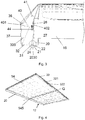
- Fig. 5 shows the carrier profiles 20 30, each with a transverse opening of the carrier profiles 20, 30 with covering cover 16 and a bracket 161 on the covers 16.
- the covers 16 the front sides of the support profiles 20, 30 are closed, so that the entire system 10 to the outside provides a closed appearance and is protected inside against contamination or tampering with arranged in the hollow sections cables or electronic plugs or components.
- FIG. 6 illustrated perspective view shows a plurality of plate-shaped objects 14 in the support frame 12.
- the through the connecting member 40 and the carrier profiles 20; 30 formed opening is closed by a cuboid, final part 50.
- the end part 50 can be formed, for example, from a plastic with low elasticity, so it can be removed if necessary.
- a gasket 52 seals against rain, which can be forced into the system by wind. However, the seal 52 is designed so that the plate-shaped objects 14 are ventilated and thereby coolable. Cooling by convection is important for increased efficiency of photovoltaic modules.
- Fig. 7A two carrier profiles 20, 30 are shown. On the support profiles 20, 30, a vertical wall 27 and 37 is formed.
- the positive connection 2030 is formed by the positive-locking elements 21, 31.
- a chamfer 24 is provided for tilting the carrier profile 20.
- the vertical walls 27 and 37 are extended upward and form a stop 29 and 39.
- the plate-shaped object 14 is placed on a web 23, 33 when inserted into the support section 20, and up to the stop 29, 39 pushed.
- the stopper 29; 39 is at a right angle at a distance which corresponds approximately to the thickness of the plate-shaped article 14, in a horizontal web 25; 35 over.
- 35 small recesses are preferably formed on the plate-shaped object 14 facing side of the horizontal web 25, 35 small recesses are preferably formed. These are filled for reliable attachment of the plate-like object 14 with an adhesive 46 which can be distributed along the inner sides of the stops 29, 39 and the pads 23, 33.
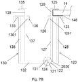
- Fig. 7B is a heavy duty variant of the two carrier profiles 120; 130 shown.
- the carrier profiles 120, 130 are formed there by two parallel vertical walls 127, 128 and 137, 138 respectively.
- the positive connection 2030 is formed analogously in this embodiment by the positive-locking elements 121, 131.
- a chamfer 124 is provided for tilting the carrier profile 120.
- interlocking elements On the upper side of the carrier profiles 120, 130 opposite the interlocking connection 2030, there are further interlocking elements with webs 126; 136 formed. These webs 126, 136 form with the vertical walls 127, 137 undercuts or longitudinal grooves 1361, 1362 into which the U-shaped webs 401, 402 of the connecting element 40 engage.
- the vertical walls 127, 137 are extended in the heavy-duty variant and form a stop 129 or 139 on each carrier profile 120, 130.
- the plate-shaped object 14 is placed on the carrier profile 120, 130 on a web 123 , 133 launched and up to the stop 129; 139 pushed.
- the stop 129, 139 is at a right angle in one Distance which corresponds approximately to the thickness of the plate-shaped article 14, in a horizontal web 125, 135 via.
- the Fig. 8 shows a perspective view with attached to the rails 42A accessories.
- a plurality of consoles 62 are arranged on the rails 42A of the connecting elements 40.
- additional elements 70 are arranged, which connect a step 80 with the console 62.
- a swivel joint 64 is formed on the bracket 62.
- a plurality of holes 74 are formed in a gate 72 and the console 62. Through the holes 74 pins 76 are inserted, whereby the console 62 with the link 72 is detachably connected.
- two fixings 78 are formed at each one of the fixings 78.
- a support tube 82 is arranged.
- the support tubes 82 are hollow-cylindrical, so that in each case a support tube 82 can optionally accommodate a likewise cylindrical support bolt 84.
- tread plates 88 can be used for different widths on the support frame 12.
- the support ribs 88 can also be used in conjunction with the support tubes 82 for adjusting the support width between the support frame 12 of adjacent photovoltaic modules 140.
- the distance between the steps 80 to each other can be adjusted by appropriate positioning set the brackets 62 in a slot 143 of the rail 42A of the connecting part 40.
- Fig. 9 is a plan view of a heavy duty variant with a frame cross member 58 shown.
- the connected carrier profiles 120, 130 are shown, which are connected to a frame cross member 58.
- a distance 56 between the upper edge of the seal 52 and the upper edge of the support frame 12 is shown.
- the Fig. 10 shows a variant of a cover 54, which is not cuboid in this embodiment, but is adapted in the heavy load variant of the shape of the opening between the connecting element 40 and the support profiles 120, 130.
- a holder 161 is shown, which is clipped into a toothed groove. With this holder 161, the lid 16, as in Fig. 5 indicated at a latching of the support frame 12 are clipped.
- connection by means of screws 60 and the positive boundary of the frame cross members 58 is also in the non-jacketed carrier profiles 20, 30 according to FIG. 1 . 3 . 5 or 7A instead of.
Landscapes
- Engineering & Computer Science (AREA)
- Chemical & Material Sciences (AREA)
- Mechanical Engineering (AREA)
- Sustainable Development (AREA)
- Sustainable Energy (AREA)
- Thermal Sciences (AREA)
- Physics & Mathematics (AREA)
- Combustion & Propulsion (AREA)
- Life Sciences & Earth Sciences (AREA)
- General Engineering & Computer Science (AREA)
- Architecture (AREA)
- Civil Engineering (AREA)
- Structural Engineering (AREA)
- Roof Covering Using Slabs Or Stiff Sheets (AREA)
- Photovoltaic Devices (AREA)
Priority Applications (2)
| Application Number | Priority Date | Filing Date | Title |
|---|---|---|---|
| EP18155221.7A EP3521729B1 (fr) | 2018-02-06 | 2018-02-06 | Système de formation d'un cadre support pour plusieurs objets en forme de plaque et disposés sur une surface |
| PCT/EP2019/051339 WO2019154614A1 (fr) | 2018-02-06 | 2019-01-21 | Système pour la formation d'un cadre de support pour plusieurs objets en forme de plaque disposés sur une surface |
Applications Claiming Priority (1)
| Application Number | Priority Date | Filing Date | Title |
|---|---|---|---|
| EP18155221.7A EP3521729B1 (fr) | 2018-02-06 | 2018-02-06 | Système de formation d'un cadre support pour plusieurs objets en forme de plaque et disposés sur une surface |
Publications (2)
| Publication Number | Publication Date |
|---|---|
| EP3521729A1 true EP3521729A1 (fr) | 2019-08-07 |
| EP3521729B1 EP3521729B1 (fr) | 2020-03-11 |
Family
ID=61167931
Family Applications (1)
| Application Number | Title | Priority Date | Filing Date |
|---|---|---|---|
| EP18155221.7A Active EP3521729B1 (fr) | 2018-02-06 | 2018-02-06 | Système de formation d'un cadre support pour plusieurs objets en forme de plaque et disposés sur une surface |
Country Status (2)
| Country | Link |
|---|---|
| EP (1) | EP3521729B1 (fr) |
| WO (1) | WO2019154614A1 (fr) |
Families Citing this family (1)
| Publication number | Priority date | Publication date | Assignee | Title |
|---|---|---|---|---|
| EP4664749A1 (fr) * | 2024-06-11 | 2025-12-17 | ABS Safety GmbH | Système de toit incliné pour au moins un module photovoltaïque |
Citations (4)
| Publication number | Priority date | Publication date | Assignee | Title |
|---|---|---|---|---|
| EP0905795A2 (fr) * | 1997-09-24 | 1999-03-31 | Matsushita Electric Works, Ltd. | Dispositif de fixation pour l'installation de modules de batteries solaires en forme de panneaux sur un toit |
| WO2004079775A2 (fr) * | 2004-07-12 | 2004-09-16 | Christian Meier | Dispositif de retenue pour elements solaires d'un champ solaire |
| DE202007006094U1 (de) * | 2007-04-27 | 2008-09-04 | Meier, Christian | Solarmodul-Anordnung mit Tragvorrichtung |
| DE102011104461A1 (de) | 2011-06-08 | 2012-12-13 | Schletter Gmbh | Anordnung eines gerahmten Photovoltaik-Moduls an einem Träger |
Family Cites Families (1)
| Publication number | Priority date | Publication date | Assignee | Title |
|---|---|---|---|---|
| FR2969189A1 (fr) * | 2010-12-15 | 2012-06-22 | Max Dolder | Dispositif support d'element en couverture de toiture et en recouvrement de facade |
-
2018
- 2018-02-06 EP EP18155221.7A patent/EP3521729B1/fr active Active
-
2019
- 2019-01-21 WO PCT/EP2019/051339 patent/WO2019154614A1/fr not_active Ceased
Patent Citations (4)
| Publication number | Priority date | Publication date | Assignee | Title |
|---|---|---|---|---|
| EP0905795A2 (fr) * | 1997-09-24 | 1999-03-31 | Matsushita Electric Works, Ltd. | Dispositif de fixation pour l'installation de modules de batteries solaires en forme de panneaux sur un toit |
| WO2004079775A2 (fr) * | 2004-07-12 | 2004-09-16 | Christian Meier | Dispositif de retenue pour elements solaires d'un champ solaire |
| DE202007006094U1 (de) * | 2007-04-27 | 2008-09-04 | Meier, Christian | Solarmodul-Anordnung mit Tragvorrichtung |
| DE102011104461A1 (de) | 2011-06-08 | 2012-12-13 | Schletter Gmbh | Anordnung eines gerahmten Photovoltaik-Moduls an einem Träger |
Also Published As
| Publication number | Publication date |
|---|---|
| EP3521729B1 (fr) | 2020-03-11 |
| WO2019154614A1 (fr) | 2019-08-15 |
Similar Documents
| Publication | Publication Date | Title |
|---|---|---|
| EP2434229B1 (fr) | Crochet de toit pour le montage de modules solaires sur des toits | |
| DE10344201A1 (de) | Solarmodulbefestigung, Verfahren zum Montieren einer Solaranlage und Anordnung aus einem Solarmodul und einem Solarmodulrahmen | |
| WO2006072230A1 (fr) | Systeme de montage a coulisseau filete | |
| EP2669451A2 (fr) | Structure porteuse et procédé de montage d'une structure porteuse | |
| DE202005006951U1 (de) | Montagesystem und Montageschiene für Dachzubehörelemente, insbesondere für Photovoltaikelemente und/oder Solarkollektoren | |
| DE202005015455U1 (de) | Einrichtung zur Montage eines Solarmoduls an einer Dachkonstruktion eines Gebäudes sowie Tragleiste zur Verwendung hierbei | |
| DE202009004746U1 (de) | Befestigungseinrichtung zum Fixieren eines Holmes oder einer Leiste an einem C-Profil | |
| DE102004057041A1 (de) | Dachmontagesystem für Solarmodule | |
| DE3906566A1 (de) | Bausatz fuer ein bauwerk | |
| EP2317246A2 (fr) | Profilé de retenue et profilé d'étanchéité pour module en forme de plaque ainsi que cadre en plusieurs parties doté de tels profilés de retenue et d'étanchéité | |
| EP3715561B1 (fr) | Système de toiture et module de support associé | |
| CH718395A2 (de) | Haltevorrichtung für Solarmodule. | |
| DE102014011364B4 (de) | Befestigungssystem zur Befestigung von plattenförmigen Fassadenelementen | |
| EP2423622B1 (fr) | Dispositif de fixation avec éléments de montage et rail de support | |
| DE102005032859B3 (de) | Befestigungssystem für Solarmodule | |
| EP2573486A2 (fr) | Élément de serrage pour un système de fixation pour éléments en forme de plaque, système de fixation comprenant un tel élément de serrage et son utilisation | |
| EP2213961A2 (fr) | Dispositif destiné à l'élévation de modules solaires | |
| WO2010051999A2 (fr) | Système de toiture intégré, fixation de profilés d'insertion sur des panneaux sandwichs présentant des rainures de dégagement | |
| EP1984582B1 (fr) | Plafond intérieur suspendu et éléments composant celui-ci | |
| DE102011055904A1 (de) | Solarmodul-Dachmontagesystem | |
| DE202019101409U1 (de) | Profilsystem zur Bildung eines Untertragrahmens für die Aufnahme von Bodenbelägen und Anschlusselement | |
| EP3521729B1 (fr) | Système de formation d'un cadre support pour plusieurs objets en forme de plaque et disposés sur une surface | |
| EP1493884B1 (fr) | poutre profilée | |
| DE202018106077U1 (de) | Glasträgerkonstruktion und Rahmenkonstruktion | |
| DE202021104820U1 (de) | Befestigungsvorrichtung zur Befestigung eines einen Teil eines Daches eines Gebäudes bildenden Photovoltaikmoduls am Gebäude und Verbindungsvorrichtungen zur Verbindung solcher Photovoltaikmodule miteinander |
Legal Events
| Date | Code | Title | Description |
|---|---|---|---|
| PUAI | Public reference made under article 153(3) epc to a published international application that has entered the european phase |
Free format text: ORIGINAL CODE: 0009012 |
|
| STAA | Information on the status of an ep patent application or granted ep patent |
Free format text: STATUS: REQUEST FOR EXAMINATION WAS MADE |
|
| 17P | Request for examination filed |
Effective date: 20180911 |
|
| AK | Designated contracting states |
Kind code of ref document: A1 Designated state(s): AL AT BE BG CH CY CZ DE DK EE ES FI FR GB GR HR HU IE IS IT LI LT LU LV MC MK MT NL NO PL PT RO RS SE SI SK SM TR |
|
| AX | Request for extension of the european patent |
Extension state: BA ME |
|
| RIC1 | Information provided on ipc code assigned before grant |
Ipc: F24S 25/60 20180101ALN20190819BHEP Ipc: F24S 25/00 20180101ALN20190819BHEP Ipc: F24S 25/634 20180101ALN20190819BHEP Ipc: F24S 50/60 20180101ALN20190819BHEP Ipc: F24S 25/33 20180101ALI20190819BHEP Ipc: F24S 25/67 20180101AFI20190819BHEP Ipc: E04D 13/12 20060101ALI20190819BHEP Ipc: F24S 25/20 20180101ALI20190819BHEP Ipc: F24S 20/20 20180101ALN20190819BHEP Ipc: F24S 20/00 20180101ALN20190819BHEP Ipc: H02S 20/23 20140101ALI20190819BHEP |
|
| GRAP | Despatch of communication of intention to grant a patent |
Free format text: ORIGINAL CODE: EPIDOSNIGR1 |
|
| STAA | Information on the status of an ep patent application or granted ep patent |
Free format text: STATUS: GRANT OF PATENT IS INTENDED |
|
| INTG | Intention to grant announced |
Effective date: 20190930 |
|
| GRAS | Grant fee paid |
Free format text: ORIGINAL CODE: EPIDOSNIGR3 |
|
| GRAA | (expected) grant |
Free format text: ORIGINAL CODE: 0009210 |
|
| STAA | Information on the status of an ep patent application or granted ep patent |
Free format text: STATUS: THE PATENT HAS BEEN GRANTED |
|
| AK | Designated contracting states |
Kind code of ref document: B1 Designated state(s): AL AT BE BG CH CY CZ DE DK EE ES FI FR GB GR HR HU IE IS IT LI LT LU LV MC MK MT NL NO PL PT RO RS SE SI SK SM TR |
|
| REG | Reference to a national code |
Ref country code: GB Ref legal event code: FG4D Free format text: NOT ENGLISH |
|
| REG | Reference to a national code |
Ref country code: CH Ref legal event code: EP |
|
| REG | Reference to a national code |
Ref country code: AT Ref legal event code: REF Ref document number: 1243611 Country of ref document: AT Kind code of ref document: T Effective date: 20200315 |
|
| REG | Reference to a national code |
Ref country code: IE Ref legal event code: FG4D Free format text: LANGUAGE OF EP DOCUMENT: GERMAN |
|
| REG | Reference to a national code |
Ref country code: DE Ref legal event code: R096 Ref document number: 502018000903 Country of ref document: DE |
|
| REG | Reference to a national code |
Ref country code: CH Ref legal event code: NV Representative=s name: NOVAGRAAF INTERNATIONAL SA, CH |
|
| PG25 | Lapsed in a contracting state [announced via postgrant information from national office to epo] |
Ref country code: RS Free format text: LAPSE BECAUSE OF FAILURE TO SUBMIT A TRANSLATION OF THE DESCRIPTION OR TO PAY THE FEE WITHIN THE PRESCRIBED TIME-LIMIT Effective date: 20200311 Ref country code: FI Free format text: LAPSE BECAUSE OF FAILURE TO SUBMIT A TRANSLATION OF THE DESCRIPTION OR TO PAY THE FEE WITHIN THE PRESCRIBED TIME-LIMIT Effective date: 20200311 Ref country code: NO Free format text: LAPSE BECAUSE OF FAILURE TO SUBMIT A TRANSLATION OF THE DESCRIPTION OR TO PAY THE FEE WITHIN THE PRESCRIBED TIME-LIMIT Effective date: 20200611 |
|
| REG | Reference to a national code |
Ref country code: NL Ref legal event code: MP Effective date: 20200311 |
|
| PG25 | Lapsed in a contracting state [announced via postgrant information from national office to epo] |
Ref country code: GR Free format text: LAPSE BECAUSE OF FAILURE TO SUBMIT A TRANSLATION OF THE DESCRIPTION OR TO PAY THE FEE WITHIN THE PRESCRIBED TIME-LIMIT Effective date: 20200612 Ref country code: BG Free format text: LAPSE BECAUSE OF FAILURE TO SUBMIT A TRANSLATION OF THE DESCRIPTION OR TO PAY THE FEE WITHIN THE PRESCRIBED TIME-LIMIT Effective date: 20200611 Ref country code: HR Free format text: LAPSE BECAUSE OF FAILURE TO SUBMIT A TRANSLATION OF THE DESCRIPTION OR TO PAY THE FEE WITHIN THE PRESCRIBED TIME-LIMIT Effective date: 20200311 Ref country code: SE Free format text: LAPSE BECAUSE OF FAILURE TO SUBMIT A TRANSLATION OF THE DESCRIPTION OR TO PAY THE FEE WITHIN THE PRESCRIBED TIME-LIMIT Effective date: 20200311 Ref country code: LV Free format text: LAPSE BECAUSE OF FAILURE TO SUBMIT A TRANSLATION OF THE DESCRIPTION OR TO PAY THE FEE WITHIN THE PRESCRIBED TIME-LIMIT Effective date: 20200311 |
|
| REG | Reference to a national code |
Ref country code: LT Ref legal event code: MG4D |
|
| PG25 | Lapsed in a contracting state [announced via postgrant information from national office to epo] |
Ref country code: NL Free format text: LAPSE BECAUSE OF FAILURE TO SUBMIT A TRANSLATION OF THE DESCRIPTION OR TO PAY THE FEE WITHIN THE PRESCRIBED TIME-LIMIT Effective date: 20200311 |
|
| PG25 | Lapsed in a contracting state [announced via postgrant information from national office to epo] |
Ref country code: PT Free format text: LAPSE BECAUSE OF FAILURE TO SUBMIT A TRANSLATION OF THE DESCRIPTION OR TO PAY THE FEE WITHIN THE PRESCRIBED TIME-LIMIT Effective date: 20200805 Ref country code: IS Free format text: LAPSE BECAUSE OF FAILURE TO SUBMIT A TRANSLATION OF THE DESCRIPTION OR TO PAY THE FEE WITHIN THE PRESCRIBED TIME-LIMIT Effective date: 20200711 Ref country code: SK Free format text: LAPSE BECAUSE OF FAILURE TO SUBMIT A TRANSLATION OF THE DESCRIPTION OR TO PAY THE FEE WITHIN THE PRESCRIBED TIME-LIMIT Effective date: 20200311 Ref country code: RO Free format text: LAPSE BECAUSE OF FAILURE TO SUBMIT A TRANSLATION OF THE DESCRIPTION OR TO PAY THE FEE WITHIN THE PRESCRIBED TIME-LIMIT Effective date: 20200311 Ref country code: EE Free format text: LAPSE BECAUSE OF FAILURE TO SUBMIT A TRANSLATION OF THE DESCRIPTION OR TO PAY THE FEE WITHIN THE PRESCRIBED TIME-LIMIT Effective date: 20200311 Ref country code: CZ Free format text: LAPSE BECAUSE OF FAILURE TO SUBMIT A TRANSLATION OF THE DESCRIPTION OR TO PAY THE FEE WITHIN THE PRESCRIBED TIME-LIMIT Effective date: 20200311 Ref country code: LT Free format text: LAPSE BECAUSE OF FAILURE TO SUBMIT A TRANSLATION OF THE DESCRIPTION OR TO PAY THE FEE WITHIN THE PRESCRIBED TIME-LIMIT Effective date: 20200311 Ref country code: SM Free format text: LAPSE BECAUSE OF FAILURE TO SUBMIT A TRANSLATION OF THE DESCRIPTION OR TO PAY THE FEE WITHIN THE PRESCRIBED TIME-LIMIT Effective date: 20200311 |
|
| REG | Reference to a national code |
Ref country code: DE Ref legal event code: R097 Ref document number: 502018000903 Country of ref document: DE |
|
| PLBE | No opposition filed within time limit |
Free format text: ORIGINAL CODE: 0009261 |
|
| STAA | Information on the status of an ep patent application or granted ep patent |
Free format text: STATUS: NO OPPOSITION FILED WITHIN TIME LIMIT |
|
| PG25 | Lapsed in a contracting state [announced via postgrant information from national office to epo] |
Ref country code: ES Free format text: LAPSE BECAUSE OF FAILURE TO SUBMIT A TRANSLATION OF THE DESCRIPTION OR TO PAY THE FEE WITHIN THE PRESCRIBED TIME-LIMIT Effective date: 20200311 Ref country code: DK Free format text: LAPSE BECAUSE OF FAILURE TO SUBMIT A TRANSLATION OF THE DESCRIPTION OR TO PAY THE FEE WITHIN THE PRESCRIBED TIME-LIMIT Effective date: 20200311 Ref country code: IT Free format text: LAPSE BECAUSE OF FAILURE TO SUBMIT A TRANSLATION OF THE DESCRIPTION OR TO PAY THE FEE WITHIN THE PRESCRIBED TIME-LIMIT Effective date: 20200311 |
|
| REG | Reference to a national code |
Ref country code: DE Ref legal event code: R082 Ref document number: 502018000903 Country of ref document: DE Representative=s name: KELLER SCHNEIDER PATENTANWALTS GMBH, DE Ref country code: DE Ref legal event code: R082 Ref document number: 502018000903 Country of ref document: DE Representative=s name: K & P PATENTANWALTSGESELLSCHAFT MBH, DE Ref country code: DE Ref legal event code: R082 Ref document number: 502018000903 Country of ref document: DE Representative=s name: K&P PATENTANWALTSGESELLSCHAFT MBH, DE |
|
| 26N | No opposition filed |
Effective date: 20201214 |
|
| PG25 | Lapsed in a contracting state [announced via postgrant information from national office to epo] |
Ref country code: PL Free format text: LAPSE BECAUSE OF FAILURE TO SUBMIT A TRANSLATION OF THE DESCRIPTION OR TO PAY THE FEE WITHIN THE PRESCRIBED TIME-LIMIT Effective date: 20200311 |
|
| REG | Reference to a national code |
Ref country code: DE Ref legal event code: R082 Ref document number: 502018000903 Country of ref document: DE Representative=s name: KELLER SCHNEIDER PATENTANWALTS GMBH, DE Ref country code: DE Ref legal event code: R082 Ref document number: 502018000903 Country of ref document: DE Representative=s name: K & P PATENTANWALTSGESELLSCHAFT MBH, DE |
|
| PG25 | Lapsed in a contracting state [announced via postgrant information from national office to epo] |
Ref country code: MC Free format text: LAPSE BECAUSE OF FAILURE TO SUBMIT A TRANSLATION OF THE DESCRIPTION OR TO PAY THE FEE WITHIN THE PRESCRIBED TIME-LIMIT Effective date: 20200311 |
|
| REG | Reference to a national code |
Ref country code: BE Ref legal event code: MM Effective date: 20210228 |
|
| PG25 | Lapsed in a contracting state [announced via postgrant information from national office to epo] |
Ref country code: LU Free format text: LAPSE BECAUSE OF NON-PAYMENT OF DUE FEES Effective date: 20210206 |
|
| PG25 | Lapsed in a contracting state [announced via postgrant information from national office to epo] |
Ref country code: IE Free format text: LAPSE BECAUSE OF NON-PAYMENT OF DUE FEES Effective date: 20210206 Ref country code: FR Free format text: LAPSE BECAUSE OF NON-PAYMENT OF DUE FEES Effective date: 20210228 |
|
| PGFP | Annual fee paid to national office [announced via postgrant information from national office to epo] |
Ref country code: GB Payment date: 20220224 Year of fee payment: 5 Ref country code: DE Payment date: 20220218 Year of fee payment: 5 Ref country code: CH Payment date: 20220217 Year of fee payment: 5 |
|
| PG25 | Lapsed in a contracting state [announced via postgrant information from national office to epo] |
Ref country code: BE Free format text: LAPSE BECAUSE OF NON-PAYMENT OF DUE FEES Effective date: 20210228 |
|
| PG25 | Lapsed in a contracting state [announced via postgrant information from national office to epo] |
Ref country code: CY Free format text: LAPSE BECAUSE OF FAILURE TO SUBMIT A TRANSLATION OF THE DESCRIPTION OR TO PAY THE FEE WITHIN THE PRESCRIBED TIME-LIMIT Effective date: 20200311 |
|
| PG25 | Lapsed in a contracting state [announced via postgrant information from national office to epo] |
Ref country code: HU Free format text: LAPSE BECAUSE OF FAILURE TO SUBMIT A TRANSLATION OF THE DESCRIPTION OR TO PAY THE FEE WITHIN THE PRESCRIBED TIME-LIMIT; INVALID AB INITIO Effective date: 20180206 |
|
| REG | Reference to a national code |
Ref country code: DE Ref legal event code: R119 Ref document number: 502018000903 Country of ref document: DE |
|
| PG25 | Lapsed in a contracting state [announced via postgrant information from national office to epo] |
Ref country code: SI Free format text: LAPSE BECAUSE OF FAILURE TO SUBMIT A TRANSLATION OF THE DESCRIPTION OR TO PAY THE FEE WITHIN THE PRESCRIBED TIME-LIMIT Effective date: 20200311 |
|
| REG | Reference to a national code |
Ref country code: CH Ref legal event code: PL |
|
| GBPC | Gb: european patent ceased through non-payment of renewal fee |
Effective date: 20230206 |
|
| PG25 | Lapsed in a contracting state [announced via postgrant information from national office to epo] |
Ref country code: LI Free format text: LAPSE BECAUSE OF NON-PAYMENT OF DUE FEES Effective date: 20230228 Ref country code: CH Free format text: LAPSE BECAUSE OF NON-PAYMENT OF DUE FEES Effective date: 20230228 |
|
| PG25 | Lapsed in a contracting state [announced via postgrant information from national office to epo] |
Ref country code: GB Free format text: LAPSE BECAUSE OF NON-PAYMENT OF DUE FEES Effective date: 20230206 |
|
| PG25 | Lapsed in a contracting state [announced via postgrant information from national office to epo] |
Ref country code: GB Free format text: LAPSE BECAUSE OF NON-PAYMENT OF DUE FEES Effective date: 20230206 Ref country code: DE Free format text: LAPSE BECAUSE OF NON-PAYMENT OF DUE FEES Effective date: 20230901 |
|
| REG | Reference to a national code |
Ref country code: AT Ref legal event code: MM01 Ref document number: 1243611 Country of ref document: AT Kind code of ref document: T Effective date: 20230206 |
|
| PG25 | Lapsed in a contracting state [announced via postgrant information from national office to epo] |
Ref country code: AT Free format text: LAPSE BECAUSE OF NON-PAYMENT OF DUE FEES Effective date: 20230206 |
|
| PG25 | Lapsed in a contracting state [announced via postgrant information from national office to epo] |
Ref country code: MK Free format text: LAPSE BECAUSE OF FAILURE TO SUBMIT A TRANSLATION OF THE DESCRIPTION OR TO PAY THE FEE WITHIN THE PRESCRIBED TIME-LIMIT Effective date: 20200311 Ref country code: AT Free format text: LAPSE BECAUSE OF NON-PAYMENT OF DUE FEES Effective date: 20230206 |
|
| PG25 | Lapsed in a contracting state [announced via postgrant information from national office to epo] |
Ref country code: MT Free format text: LAPSE BECAUSE OF FAILURE TO SUBMIT A TRANSLATION OF THE DESCRIPTION OR TO PAY THE FEE WITHIN THE PRESCRIBED TIME-LIMIT Effective date: 20200311 |
|
| PG25 | Lapsed in a contracting state [announced via postgrant information from national office to epo] |
Ref country code: TR Free format text: LAPSE BECAUSE OF FAILURE TO SUBMIT A TRANSLATION OF THE DESCRIPTION OR TO PAY THE FEE WITHIN THE PRESCRIBED TIME-LIMIT Effective date: 20200311 |
|
| PGFP | Annual fee paid to national office [announced via postgrant information from national office to epo] |
Ref country code: AT Payment date: 20260410 Year of fee payment: 5 |