EP3521860A1 - Dispositif capteur optoélectronique - Google Patents
Dispositif capteur optoélectronique Download PDFInfo
- Publication number
- EP3521860A1 EP3521860A1 EP19151190.6A EP19151190A EP3521860A1 EP 3521860 A1 EP3521860 A1 EP 3521860A1 EP 19151190 A EP19151190 A EP 19151190A EP 3521860 A1 EP3521860 A1 EP 3521860A1
- Authority
- EP
- European Patent Office
- Prior art keywords
- distance
- area
- floor
- sensor device
- expected
- Prior art date
- Legal status (The legal status is an assumption and is not a legal conclusion. Google has not performed a legal analysis and makes no representation as to the accuracy of the status listed.)
- Granted
Links
Images



Classifications
-
- G—PHYSICS
- G01—MEASURING; TESTING
- G01S—RADIO DIRECTION-FINDING; RADIO NAVIGATION; DETERMINING DISTANCE OR VELOCITY BY USE OF RADIO WAVES; LOCATING OR PRESENCE-DETECTING BY USE OF THE REFLECTION OR RERADIATION OF RADIO WAVES; ANALOGOUS ARRANGEMENTS USING OTHER WAVES
- G01S17/00—Systems using the reflection or reradiation of electromagnetic waves other than radio waves, e.g. lidar systems
- G01S17/02—Systems using the reflection of electromagnetic waves other than radio waves
- G01S17/06—Systems determining position data of a target
- G01S17/42—Simultaneous measurement of distance and other co-ordinates
-
- G—PHYSICS
- G01—MEASURING; TESTING
- G01S—RADIO DIRECTION-FINDING; RADIO NAVIGATION; DETERMINING DISTANCE OR VELOCITY BY USE OF RADIO WAVES; LOCATING OR PRESENCE-DETECTING BY USE OF THE REFLECTION OR RERADIATION OF RADIO WAVES; ANALOGOUS ARRANGEMENTS USING OTHER WAVES
- G01S17/00—Systems using the reflection or reradiation of electromagnetic waves other than radio waves, e.g. lidar systems
- G01S17/87—Combinations of systems using electromagnetic waves other than radio waves
-
- G—PHYSICS
- G01—MEASURING; TESTING
- G01S—RADIO DIRECTION-FINDING; RADIO NAVIGATION; DETERMINING DISTANCE OR VELOCITY BY USE OF RADIO WAVES; LOCATING OR PRESENCE-DETECTING BY USE OF THE REFLECTION OR RERADIATION OF RADIO WAVES; ANALOGOUS ARRANGEMENTS USING OTHER WAVES
- G01S17/00—Systems using the reflection or reradiation of electromagnetic waves other than radio waves, e.g. lidar systems
- G01S17/88—Lidar systems specially adapted for specific applications
- G01S17/93—Lidar systems specially adapted for specific applications for anti-collision purposes
- G01S17/931—Lidar systems specially adapted for specific applications for anti-collision purposes of land vehicles
-
- G—PHYSICS
- G01—MEASURING; TESTING
- G01S—RADIO DIRECTION-FINDING; RADIO NAVIGATION; DETERMINING DISTANCE OR VELOCITY BY USE OF RADIO WAVES; LOCATING OR PRESENCE-DETECTING BY USE OF THE REFLECTION OR RERADIATION OF RADIO WAVES; ANALOGOUS ARRANGEMENTS USING OTHER WAVES
- G01S7/00—Details of systems according to groups G01S13/00, G01S15/00, G01S17/00
- G01S7/48—Details of systems according to groups G01S13/00, G01S15/00, G01S17/00 of systems according to group G01S17/00
- G01S7/4802—Details of systems according to groups G01S13/00, G01S15/00, G01S17/00 of systems according to group G01S17/00 using analysis of echo signal for target characterisation; Target signature; Target cross-section
-
- G—PHYSICS
- G01—MEASURING; TESTING
- G01S—RADIO DIRECTION-FINDING; RADIO NAVIGATION; DETERMINING DISTANCE OR VELOCITY BY USE OF RADIO WAVES; LOCATING OR PRESENCE-DETECTING BY USE OF THE REFLECTION OR RERADIATION OF RADIO WAVES; ANALOGOUS ARRANGEMENTS USING OTHER WAVES
- G01S7/00—Details of systems according to groups G01S13/00, G01S15/00, G01S17/00
- G01S7/48—Details of systems according to groups G01S13/00, G01S15/00, G01S17/00 of systems according to group G01S17/00
- G01S7/4808—Evaluating distance, position or velocity data
Definitions
- the present invention relates to an optoelectronic sensor device having a distance sensor aligned on a floor, in particular a laser scanner, which determines distance information for at least one monitoring area, the at least one monitoring area covering a floor area which forms a surface area of the floor.
- Such optoelectronic sensor devices find use in a variety of applications. For example, they may be stationary and serve to monitor a shelter of a dangerous machine. In this case, by means of the first monitoring range, e.g. the legs are detected by persons. If the presence of a person or an object in the shelter is detected by the sensor device in this way, the machine can be switched off so as not to endanger the person.
- the first monitoring range e.g. the legs are detected by persons. If the presence of a person or an object in the shelter is detected by the sensor device in this way, the machine can be switched off so as not to endanger the person.
- optoelectronic sensor devices can also be used for mobile applications, in particular they can enable operation of vehicles and self-propelled vehicles.
- Self-propelled vehicles also called AGVs (Automated Guided Vehicle)
- AGVs Automated Guided Vehicle
- a mounted on the vehicle laser scanner sensor device is used, which is mounted approximately 15 to 30 cm above the ground and, for example, scans an aligned in the direction of travel of the vehicle surveillance area.
- the laser scanner can in particular a distance sensor whose monitoring area extends parallel to the ground and defines a flat surface.
- a complete detection of obstacles of any kind could be achieved by an advanced sensor, for example, in addition to the distance sensor even more optical sensors, such as a camera, are provided to detect the environment of the sensor device substantially completely three-dimensional.
- optical sensors such as a camera
- the object is achieved by an optoelectronic sensor device according to claim 1.
- the optoelectronic sensor device has a ground-oriented distance sensor, in particular a laser scanner, which determines distance information for at least one monitoring area, wherein the at least one monitoring area covers a floor area which forms a surface area of the floor. Furthermore, the sensor device has an evaluation unit, which is designed to detect a deviation from at least one expected floor area based on the distance information, and to output a signal, in particular a warning signal, upon detection of a deviation.
- the at least one expected floor area is based on a predefined model, which represents the distance information for the at least one monitoring area for the theoretical case, in which the distance sensor is in a known reference position and is aligned with a known reference floor.
- the monitoring area partially covers the ground, ie comprises a surface area of the floor.
- the surveillance area thus runs at least in sections not parallel but at an angle to the ground, so that the surveillance area intersects the ground in the geometric sense.
- the surveillance area thus, starting from the distance sensor, it is inclined towards the floor and intersects the floor in a certain floor area which, due to the geometry of the surveillance area and the floor, can be assigned to the surveillance area. In this way, it is ensured that the distance sensor always "sees" the ground and, in particular, can also detect flat objects on the ground as well as soil anomalies.
- a plurality of monitoring areas are provided, each covering an associated floor area.
- the recognition of objects and soil anomalies is based on the distance information, which is evaluated depending on at least one expected ground area.
- an associated expected floor area is preferably provided for each covered floor area.
- a respective expected floor area indicates the floor area that the device would expect with respect to the determined distance information when there is no object and no floor anomaly.
- the expected floor area represents a normal area that serves to determine if an object and / or floor anomaly is in the particular surveillance area.
- the expected floor area may be defined by one or more distance limits to indicate a range of distance values between the distance sensor and the floor. If the distance information determined for the currently covered floor area is within the range of distance values, it can be assumed that there is no object and no floor anomaly in the monitored area.
- the expected floor area may be spatially variable and defined by one or more geometrically interpretable parameters. Such parameters may, in particular, be distance values with respect to those determined by the distance sensor Distance information, but also other parameters, such as to describe a contour in space.
- the distance sensor preferably optically scans a line-shaped bottom area and delivers distance information, ie depth information, for the scanned line.
- the distance sensor is preferably designed as a laser scanner with a rotatable scan head which determines distance information via a light transit time measurement of laser pulses emitted by the distance sensor itself. For example, a laser pulse is emitted at periodic intervals, which provides a distance point for an associated rotational position of the scan head. For each of the distance points determined in this way, it can be determined whether the associated distance value lies within the expected ground area.
- an associated upper and lower distance limit value can be stored for each respective rotational position of the scan head, which is compared with the distance of the distance point determined for the relevant rotational position. If the measured distance does not exceed the upper distance value and does not fall below the lower distance limit value, the relevant distance point can be assigned to the expected ground area. That it is assumed that the laser pulse is taken to measure the distance to the ground, not an object or a soil anomaly. Should the measured distance violate any of the distance limits, this is an indication of an object or ground anomaly, e.g. in the case of too small distances to an object and in case of too large distances to a soil anomaly can be concluded.
- the expected floor area is based on a predefined model, which represents the distance information for the at least one monitoring area for the theoretical case, in which the distance sensor is located in a known reference position and is aligned with a known reference floor.
- the predefined model is therefore based on a-priori knowledge, in particular about a mounting bracket and / or a mounting position of the distance sensor.
- the expected ground area represents a model-based reference for detecting objects and soil anomalies.
- the determined distance information preferably does not have to exactly match the predefined model in order to exclude an object or a soil anomaly. Rather, the expected floor area may be a tolerance range that provides greater reliability in detection.
- the expected floor area defined on the basis of the model can be adapted, as will be explained in more detail below.
- the reference position of the distance sensor preferably comprises the spatial position of the distance sensor and its orientation relative to the ground.
- the orientation may include at least one tilt angle of the proximity sensor relative to the ground. From the angle of inclination, the course of the monitoring area relative to the distance sensor and the ground can be specified.
- the spatial position of the distance sensor may in particular comprise only the distance of the distance sensor from the reference bottom, ie the reference height of the distance sensor.
- the reference floor can generally be defined as a mathematical function and by parameters that specify the spatial position and the course of the reference floor.
- the reference position of the distance sensor and the reference bottom are defined relative to each other, ie absolute position information is not necessary.
- the expected floor area can advantageously be determined.
- the expected floor area is thus based on a geometric arrangement of the distance sensor relative to a reference floor. This arrangement does not have to be achieved in an actual operation of the sensor device, but reflects a mathematically defined ideal case (theoretical case).
- This allows the predefined or deterministic model of the sensor device comparatively be easily parameterized. Among other things, this allows a particularly simple adaptation of the model to a specific sensor device, for example by merely changing one or more parameters of the model.
- the use of such a predefined model thus has advantages over other models, in particular those that have to be elaborately determined or trained or initialized only in the actual operation of a sensor device.
- the reference floor can be, for example, a level that exists exclusively virtually and is clearly defined by geometric parameters.
- the term "soil” may in particular refer to a substrate of any nature.
- the floor is geometrically at least similar to a flat floor, such as a building.
- the floor may also be a wall or ceiling of a building to be monitored.
- the output signal may be, for example, a notification signal, a brake signal and / or an alternate signal.
- the signal may, for example, initiate a brake and / or evasive maneuver.
- the predefined model of the sensor device may be a geometric model that does not depend on distance information determined by the distance sensor in actual operation of the optoelectronic sensor device.
- the geometric model it is possible to calculate the expected floor area e.g. by defining only two defined points and the information that the expected floor area comprises a straight line or a line passing through the two defined points.
- the straight line or the line can still be surrounded by the already mentioned tolerance range, wherein the tolerance range also counts to the expected floor area.
- the line may also have the shape of a hyperbola, in particular if there is a tilt angle, as described later.
- the predefined model or the expected floor area can thus be described in a simple way mathematically or geometrically.
- the model can be easily stored in the optoelectronic device, wherein a potentially erroneous training operation of the device for determining the model is not necessary.
- the predefined model may be defined by one or more fixed parameters that may be separately adjusted, e.g. to set the reference position of the distance sensor or a derived therefrom size.
- the reference position is preferably a position of the distance sensor provided for the operation of the sensor device.
- the at least one monitoring area and the ground include an angle which is less than forty, preferably less than thirty degrees.
- the distance sensor may for this purpose preferably be positioned at a low height above the floor and aligned in such a way that the monitoring area runs at the desired angle relative to the floor. It is understood that the angle between the monitoring area and the floor can be variable in sections, for example if the monitoring area has a spatially curved course.
- a small or "flat" angle between The surveillance area and the floor have the advantage that the determined distance information changes greatly relative to the height of a flat object when the flat object enters the surveillance area. Thus, flat objects and, for the same reason, soil anomalies can be detected particularly reliably.
- the model comprises at least one reference distance contour, which is based on the reference position and the reference bottom, wherein the at least one expected bottom area forms a tolerance range around the at least one reference distance contour.
- the expected bottom area preferably represents a tolerance range around the reference distance contour, which would theoretically coincide with the determined distances if the distance sensor were located in the reference position and thus would be aligned with the reference bottom.
- the recognition of objects is based on a tolerance range, ie. the distances determined may be slightly larger or smaller, and preferably no object or ground anomaly is detected if the distances are still within the expected floor area.
- the expected floor area can in particular be based exclusively on the reference distance contour.
- the expected floor area may be particularly in use of the sensor device in a non-stationary, i. mobile application (e.g., in a vehicle), as will be explained below.
- the reference bottom can be defined in particular by a flat surface. Generally, however, the reference bottom can be defined by any surface be, which preferably corresponds at least approximately to the ground, which is to be covered in regions of the distance sensor during operation of the sensor device. Likewise, the reference position of the distance sensor at least substantially correspond to the intended for the actual operation of the sensor device operating position.
- the at least one monitoring area comprises a plane and / or curved surface that intersects at least partially with the reference bottom, wherein the intersection line between the surface and the reference bottom forms the at least one reference spacing contour.
- an expected floor area and a reference distance contour may be provided for each monitoring area, which results from a respective intersection line of the assigned monitoring area.
- the reference spacing contours can be designed differently, just like the monitoring areas. As a result, e.g. for a particular application, specific patterns of surveillance areas are designed to optimize the sensing performance of the sensing device.
- the expected floor areas associated with the monitoring areas may all be based on the same predefined model, preferably using known sensor-specific information indicating a fixed relationship between the monitoring areas that does not change during operation of the sensor device.
- the evaluation unit is designed to determine the at least one expected floor area on the basis of the predefined model, in particular on the basis of an associated reference distance contour. This can also be determined by the evaluation unit, in particular (once) in the context of an initialization of the Sensor device. Alternatively to a determination of the expected floor area, this can also be stored in the sensor device, for example in the sense of a "factory setting".
- the evaluation unit is designed to adapt the at least one expected floor area as a function of currently determined distance information.
- Such an adaptation of the floor area which may be termed adaptive because of the consideration of current distance information, is particularly advantageous if the actual position of the distance sensor and / or the actual floor deviate from the reference assumptions, ie the reference position and the reference floor. This may be the case, for example, if the contour of the ground changes slowly due to unevenness or, in the case of a sensor device mounted on a vehicle, if the position of the sensor device changes due to loading and / or vehicle movements. Such a deviation from the reference assumptions should not lead to the falsely recognizing an object or a soil anomaly.
- the deviation from the reference assumptions should not result in a deviation from the expected ground area being detected on the basis of the distance information determined, although no object or ground anomaly is present in the monitored area.
- a precautionary increase in the expected floor area which could also prevent misdetections, is avoided, however, as this would degrade the reliability of the detection (small objects are not detected).
- it can be determined on the basis of the currently determined distance information whether the currently expected ground area at least approximately matches the currently determined distance information.
- an adaptation of the expected floor area can be made, which compensates for these deviations.
- An adaptation can in particular at regular time intervals, eg in the course of a respective Scans of the distance sensor done. In this way, the expected floor area can thus be adjusted dynamically and adaptively, so that both stationary and short-term changes in the sensor position can be compensated efficiently and do not adversely affect the detection performance of the sensor device.
- distance information can thus be repeatedly determined, wherein a repeated adaptation of the expected floor area is carried out, wherein the adjustment of the expected floor area is carried out in each case on the basis of current distance information.
- an adaptation of the predefined model can also be made. This can e.g. be meaningful if a permanent or constant deviation from the reference assumptions is determined and a related repeated adaptation of the expected floor area is to be avoided, e.g. after commissioning the sensor device and associated initialization based on the predefined model.
- the determined distance information may comprise a plurality of distance points, wherein the evaluation unit is configured to adapt the expected ground area as a function of a subset of the plurality of distance points, wherein the subset of the plurality of distance points comprises distance points of the determined distance information lying within the at least one expected ground area and / or lie within a tolerance range around a reference distance contour of the predefined model and / or do not exceed a predefined first maximum distance and / or do not exceed a predefined second maximum distance to an adjacent distance point.
- Each of these selection criteria is designed to prevent the expected floor area from being adjusted based on distance points that are not valid. A false adjustment is thus effectively avoided.
- a pre-processing can initially take place, in which - as explained above - not valid distance points are eliminated. Subsequently, a fitting of the expected floor area (and also of the predefined model) can take place at the distance points remaining after the pre-processing.
- the distance points can serve as support points for the expected floor area or the predefined model.
- the adaptation of the expected ground area thus takes place during the operation of the sensor device, whereby in each case an adaptation to a current scan (that is to say to the current distance information) preferably takes place.
- a respective expected floor area is based on the respective preceding expected floor area.
- the continuous adaptation of the expected floor area or model to the current distance information is particularly suitable for indoor applications where there are only slight (e.g., non-erratic) changes, e.g. of the actual soil and thus the distance information can be expected.
- the sensor device can advantageously be used indoors, wherein the expected floor area can be adapted particularly precisely to the actual floor in order to optimize the recognition performance of the sensor device.
- the sensor device can also be used outdoors, in particular in defined environments.
- the tolerance range may, for example, have a size or width of less than 5 cm, preferably less than 3 cm or particularly preferably less than 1 cm.
- the expected floor area and optionally also the (initial) predefined model can be continuously adaptive during operation be adjusted.
- the adaptive adaptation of the expected floor area achieves a particular robustness against uneven floors and, for example, against pitching movements of an automated vehicle.
- the predefined model reliably prevents inaccurate or incorrectly expected ground areas as well as incorrect adjustments of the expected ground area.
- the distance sensor may be adapted to determine distance information for two to six, preferably four, surveillance areas, each of the surveillance areas covering one, preferably respectively different, floor area, and the covered floor areas being preferably spaced from each other.
- the distance sensor can thus be designed as a "multi-layer scanner", whereby a reliable monitoring is achieved.
- the failure of the proximity sensor with respect to a single monitored area e.g., a laser diode
- the floor may be sampled, i. be detected particularly efficiently.
- the distance sensor can comprise a plurality of mutually tilted laser sensors on a rotatable scan head. Due to the tilted laser sensors, laser pulses can be emitted by a respective laser sensor in the course of a complete rotation of the scan head, which together form the shape of a cone or truncated cone.
- One of the laser sensors can also be arranged such that the in Define a plane during a complete rotation of the scan head emitted laser pulses.
- Each laser sensor can cover a separate floor area.
- Each separate floor area can be evaluated separately to detect objects.
- a separate predefined model exists for each separate floor area, on which in turn the expected floor area for the respective separate floor area is based. If a deviation from the expected floor area is detected at least in one of the separate floor areas, a signal (in particular a warning signal) is output. Alternatively, it is also possible that only when a deviation is detected in at least two or three separate floor areas a signal is output.
- the various expected floor areas or predefined models for the separate floor areas can each be adapted independently of each other on the basis of the respective current distance information, as explained in more detail above.
- This has the advantage that the number of monitoring areas can be varied slightly depending on the distance sensor used.
- plausibility checks may be performed based on information from multiple monitoring areas, particularly as regards the selection of distance points that may be used to adjust an expected floor area, as described above.
- a signal can only be output if an object or a soil anomaly has been detected in at least two or three monitoring areas.
- the evaluation unit is adapted to determine a current position of the distance sensor. Based on the determined Lü the reference position of the predefined model can be initialized or updated.
- the evaluation unit for evaluating the distance information is a computing device of the distance sensor.
- the data processing of the distance sensor can take place wholly or partly in the distance sensor.
- the computing device of the distance sensor is usually very powerful and beyond can be designed as a safe or intrinsically safe component.
- the computing device of the distance sensor can then also communicate with a control unit, for example, to transmit a warning signal or generally a signal.
- the distance sensor may be intrinsically safe and have secure communication interfaces.
- the invention certainly further relates to a vehicle having an optoelectronic sensor device according to one of the embodiments described above, and a control unit, an evaluation unit, which is designed to detect a deviation from at least one expected floor area based on the distance information, and a signal when a deviation is detected , in particular a warning signal, to the control unit.
- the distance sensor transmits the distance information to the evaluation unit. This can then perform the recognition of a deviation from the expected floor area.
- the evaluation unit communicates with a control unit, for example, and transmits a warning signal to the control unit if an object or a soil anomaly has been detected.
- the control unit can then initiate appropriate measures in response to the warning signal, eg the stop of the machine or of the vehicle, an evasion of the vehicle or a warning of a user by optical or acoustic signals.
- the warning signal can also initiate such actions directly.
- the evaluation unit is designed to adapt the predefined model to acceleration-dependent movements of the vehicle.
- the adaptation of the expected ground area in dependence on currently determined distance information can be improved by explicitly taking into account the effect of the acceleration-related movement, e.g. by the timing and / or the size of the movement. This is particularly useful when the vehicle is self-propelled and the safe detection performance of the sensor device is particularly important.
- the invention also relates to a method for operating an optoelectronic sensor device in which distance information for at least one monitoring area is determined by a distance sensor aligned on a floor, in particular a laser scanner, wherein the at least one monitoring area covers a floor area, with an evaluation unit on the basis of Distance information is detected a deviation from at least one expected ground area, and when detection of a deviation, a warning signal is output, the at least one expected ground area based on a predefined model, which represents the distance information for the at least one monitoring area in the event that the distance sensor is located in a known reference position and is aligned with a known reference bottom.
- An application of the invention may also generally be to detect the nature of the soil. On the basis of the recorded soil condition, a "map" can be created for vehicles that have a different sensor system and as a precaution, avoid soil anomalies due to the map.
- a vehicle 10 which is preferably self-propelled, has an optoelectronic sensor device 12, which comprises a distance sensor aligned with a floor 14 ( Fig. 1 ).
- the distance sensor (not shown) is preferably integrated in the sensor device 12.
- an evaluation unit is provided, which is connected to a control unit of the vehicle 10 (not shown).
- the distance sensor of the sensor device 12 determines distance information for four monitoring areas 16a, 16b, 16c, 16d, each covering a portion of the floor 14 cover.
- the distance information determined for each monitoring area 16a, 16b, 16c, 16d is compared with a respective expected floor area, wherein in case of a deviation an object and / or a floor anomaly is detected.
- a deviation an object and / or a floor anomaly is detected.
- an object 18 disposed on the floor 14 is detected by the monitoring areas 16a, 16b. Due to the resulting change in the distance information (measured distance reduced), the comparatively flat object 18 is reliably detected.
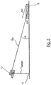
- Fig. 2 the geometry of the arrangement of the sensor device 12 is illustrated relative to the bottom 14, wherein in Fig. 2 only the monitoring area 16a is shown.
- the monitoring area 16a has an angle ⁇ with respect to the floor 14, which can be considered small.
- the distance change ⁇ R caused by the object 18 is large in comparison to the small height ⁇ h of the object 18.
- the object 18 can therefore be reliably detected despite its small height.
- dR d.alpha - cos ⁇ sin 2 ⁇ H sensor
- h sensor is the mounting height of the distance sensor, that is, the orthogonal distance between the bottom 14 and the distance sensor, which is integrated in the sensor device 12.
- h sensor is the mounting height of the distance sensor, that is, the orthogonal distance between the bottom 14 and the distance sensor, which is integrated in the sensor device 12.
- h sensor and ⁇ are determined which indicate a reference position of the distance sensor relative to the bottom 14.
- the bottom 14 is a plane that acts as a reference bottom.
- the corresponding cut contours represent reference contours that are used to determine expected floor areas as described above, such as the expected floor areas 28a, 28b, 28c, 28d of FIG Fig. 4 ,
- Fig. 3 shows a sensor board 20 which is rotatably mounted about an axis S and a sensor head of the distance sensor of the sensor device 12.
- the distance sensor can therefore also be referred to as a laser scanner.
- Each of the laser sensors 22a, 22b, 22c, 22d measures distances by laser beams 26 that are tilted relative to the sensor board 20 at a respective individual angle.
- Guides 24 are drawn, which are parallel to the plane of the sensor board 20.
- the tilt angles of the laser sensors 22a, 22b, 22c, 22d are +5, +2.5, 0 and -2.5 degrees.
- the sensor board 20 is when used in the sensor device 12 of Fig. 1 and Fig. 2 inclined by the angle ⁇ relative to the bottom 14 to form the monitoring areas 16a, 16b, 16c, 16d ( Fig. 1 ). It is understood that other distance sensors can be provided with other monitoring areas.
- Fig. 4 For example, four separate expected floor areas 28a, 28b, 28c, 28d are shown that correspond to the floor areas covered by the monitor areas 16a, 16b, 16c, 16d when the sensor board 20 from Fig. 3 is rotated and no object is in the monitoring areas 16a, 16b, 16c, 16d.
- Fig. 4 thus represents a plan view of the bottom 14 (perspective perpendicular to the ground plane), wherein the expected bottom portions 28a, 28b, 28c, 28d are marked.
- distance points 30, 32 are determined by continuously periodic laser pulse measurements by means of the laser sensors 22a, 22b, 22c, 22d.
- the laser pulses emitted for measuring the distance points 30 hit the floor 14 unhindered (ie there is no object in the monitoring areas 16a, 16b, 16c, 16d) and the bottom 14 has no bottom anomaly (eg a depression). If, however, distance points 32 are measured which lie outside the expected floor areas 28a, 28b, 28c, 28d (or outside their tolerance ranges), it can be assumed that an object or floor anomaly in the monitoring areas 16a, 16b, 16c, 16d is located, ie the distance points 32 are not assigned to the bottom 14.
- Fig. 4 The distance points 32 fall below the expected floor areas 28a and 28b. This corresponds with Fig. 1 in that the object 18 is detected by the monitoring areas 16a and 16b and the distance points 32 lying on the object 18 have reduced distances to the sensor device 12, which lie outside the expected floor areas 28a and 28b.
Landscapes
- Physics & Mathematics (AREA)
- Engineering & Computer Science (AREA)
- Electromagnetism (AREA)
- Computer Networks & Wireless Communication (AREA)
- General Physics & Mathematics (AREA)
- Radar, Positioning & Navigation (AREA)
- Remote Sensing (AREA)
- Length Measuring Devices By Optical Means (AREA)
- Optical Radar Systems And Details Thereof (AREA)
- Control Of Position, Course, Altitude, Or Attitude Of Moving Bodies (AREA)
Applications Claiming Priority (1)
| Application Number | Priority Date | Filing Date | Title |
|---|---|---|---|
| DE102018102287.5A DE102018102287A1 (de) | 2018-02-01 | 2018-02-01 | Optoelektronische Sensorvorrichtung |
Publications (2)
| Publication Number | Publication Date |
|---|---|
| EP3521860A1 true EP3521860A1 (fr) | 2019-08-07 |
| EP3521860B1 EP3521860B1 (fr) | 2020-12-16 |
Family
ID=65013582
Family Applications (1)
| Application Number | Title | Priority Date | Filing Date |
|---|---|---|---|
| EP19151190.6A Active EP3521860B1 (fr) | 2018-02-01 | 2019-01-10 | Dispositif capteur optoélectronique |
Country Status (2)
| Country | Link |
|---|---|
| EP (1) | EP3521860B1 (fr) |
| DE (1) | DE102018102287A1 (fr) |
Cited By (1)
| Publication number | Priority date | Publication date | Assignee | Title |
|---|---|---|---|---|
| EP4109127A1 (fr) | 2021-06-21 | 2022-12-28 | Sick Ag | Capteur optoélectronique et procédé de détection des objets |
Families Citing this family (2)
| Publication number | Priority date | Publication date | Assignee | Title |
|---|---|---|---|---|
| DE102019217988A1 (de) * | 2019-11-21 | 2021-05-27 | Zf Friedrichshafen Ag | Kamerabasierte Detektion von Kippbewegungen |
| EP4401045B1 (fr) | 2023-01-10 | 2024-10-30 | Sick Ag | Configuration de capteur 3d pour un suivi d'objet sécurisé |
Citations (3)
| Publication number | Priority date | Publication date | Assignee | Title |
|---|---|---|---|---|
| EP2192384A1 (fr) * | 2008-11-27 | 2010-06-02 | DS Automation GmbH | Dispositif et procédé de détermination optique de la position d'un véhicule |
| US7741961B1 (en) * | 2006-09-29 | 2010-06-22 | Canesta, Inc. | Enhanced obstacle detection and tracking for three-dimensional imaging systems used in motor vehicles |
| DE102013207147A1 (de) * | 2012-05-03 | 2013-11-07 | Ifm Electronic Gmbh | System und Verfahren zur Erfassung eines Fahrbahnprofils |
Family Cites Families (2)
| Publication number | Priority date | Publication date | Assignee | Title |
|---|---|---|---|---|
| DE102011080932A1 (de) * | 2011-08-12 | 2013-02-14 | Robert Bosch Gmbh | Verfahren zur Unterstützung eines Fahrers eines Fahrzeuges |
| DE102014217352B4 (de) * | 2014-08-29 | 2018-04-19 | HAP Handhabungs-, Automatisierungs- und Präzisionstechnik GmbH | Verfahrbare Vorrichtung zur Manipulation von Gegenständen |
-
2018
- 2018-02-01 DE DE102018102287.5A patent/DE102018102287A1/de not_active Withdrawn
-
2019
- 2019-01-10 EP EP19151190.6A patent/EP3521860B1/fr active Active
Patent Citations (3)
| Publication number | Priority date | Publication date | Assignee | Title |
|---|---|---|---|---|
| US7741961B1 (en) * | 2006-09-29 | 2010-06-22 | Canesta, Inc. | Enhanced obstacle detection and tracking for three-dimensional imaging systems used in motor vehicles |
| EP2192384A1 (fr) * | 2008-11-27 | 2010-06-02 | DS Automation GmbH | Dispositif et procédé de détermination optique de la position d'un véhicule |
| DE102013207147A1 (de) * | 2012-05-03 | 2013-11-07 | Ifm Electronic Gmbh | System und Verfahren zur Erfassung eines Fahrbahnprofils |
Cited By (4)
| Publication number | Priority date | Publication date | Assignee | Title |
|---|---|---|---|---|
| EP4109127A1 (fr) | 2021-06-21 | 2022-12-28 | Sick Ag | Capteur optoélectronique et procédé de détection des objets |
| CN115575924A (zh) * | 2021-06-21 | 2023-01-06 | 西克股份公司 | 用于检测对象的光电传感器和方法 |
| JP2023001875A (ja) * | 2021-06-21 | 2023-01-06 | ジック アーゲー | 光電センサ及び物体検出方法 |
| CN115575924B (zh) * | 2021-06-21 | 2026-02-24 | 西克股份公司 | 用于检测对象的光电传感器和方法 |
Also Published As
| Publication number | Publication date |
|---|---|
| DE102018102287A1 (de) | 2019-08-01 |
| EP3521860B1 (fr) | 2020-12-16 |
Similar Documents
| Publication | Publication Date | Title |
|---|---|---|
| DE10141294B4 (de) | Verfahren zur Bodenerkennung | |
| EP1643271B1 (fr) | Procédé et dispositif pour classifier des limites latéraux d'une place de stationnement pour un système d'assistance au stationnement d'un véhicule automobile | |
| EP3435117B1 (fr) | Capteur et procédé de détection et de détermination des distances entre des objets | |
| EP1927867A1 (fr) | Capteur optoélectronique à plusieurs plans et procédé de détection d'objets | |
| EP2339376A1 (fr) | Capteur optoélectronique | |
| DE19832790A1 (de) | Hindernis-Erkennungssystem für Kraftfahrzeuge | |
| DE102008032216A1 (de) | Vorrichtung zur Erkennung der Anwesenheit eines Objekts im Raum | |
| EP3521860B1 (fr) | Dispositif capteur optoélectronique | |
| WO2011098608A1 (fr) | Dispositif de marquage et système d'arpentage de terrains | |
| EP1224644B1 (fr) | Dispositif pour reguler le flux de circulation a un carrefour, notamment pour reguler les feux | |
| EP3026459B1 (fr) | Systeme de capteur | |
| DE10033608A1 (de) | Verfahren und Vorrichtung zum Absichern eines Gefahrenbereichs, insbesondere des Gefahrenbereichs einer automatisiert arbeitenden Maschine | |
| EP1612578A1 (fr) | Procédé de fonctionnement d'un radar | |
| EP3738420B1 (fr) | Procédé de fonctionnement d'un engin agricole automatique | |
| DE102017124962B4 (de) | Vermeidung von falschen Objekterfassungen bei Hindernissen oberhalb eines Fahrzeugs | |
| DE102021112709B4 (de) | LiDAR Laser-Scanner | |
| WO2022194746A1 (fr) | Procédé de fonctionnement d'un dispositif à capteurs ultrasonores pour surveiller une zone de soubassement de carrosserie d'un véhicule automobile, produit-programme informatique, support de stockage lisible par ordinateur et dispositif à capteurs ultrasonores | |
| DE202014105727U1 (de) | Sensorsystem | |
| DE102011000514A1 (de) | Automatische Türschwenkvorrichtung | |
| DE60303577T2 (de) | Verfahren zum Überwachen der Umgebung eines Fahrzeugs | |
| EP3710905B1 (fr) | Système d'infrastructure | |
| WO2022248479A1 (fr) | Procédé et dispositif de détection d'un blocage d'un système lidar, et véhicule correspondant | |
| EP4726428A1 (fr) | Dispositif de capteur et système de détection d'une zone de conduite d'un robot industriel | |
| EP4564052A1 (fr) | Capteur à touche optique | |
| DE102021213080A1 (de) | Vorrichtung für ein Baustellenmarkierungselement zum Erkennen einer Bereichsverletzung |
Legal Events
| Date | Code | Title | Description |
|---|---|---|---|
| PUAI | Public reference made under article 153(3) epc to a published international application that has entered the european phase |
Free format text: ORIGINAL CODE: 0009012 |
|
| STAA | Information on the status of an ep patent application or granted ep patent |
Free format text: STATUS: THE APPLICATION HAS BEEN PUBLISHED |
|
| AK | Designated contracting states |
Kind code of ref document: A1 Designated state(s): AL AT BE BG CH CY CZ DE DK EE ES FI FR GB GR HR HU IE IS IT LI LT LU LV MC MK MT NL NO PL PT RO RS SE SI SK SM TR |
|
| AX | Request for extension of the european patent |
Extension state: BA ME |
|
| STAA | Information on the status of an ep patent application or granted ep patent |
Free format text: STATUS: REQUEST FOR EXAMINATION WAS MADE |
|
| RAP1 | Party data changed (applicant data changed or rights of an application transferred) |
Owner name: SICK AG |
|
| 17P | Request for examination filed |
Effective date: 20200204 |
|
| RBV | Designated contracting states (corrected) |
Designated state(s): AL AT BE BG CH CY CZ DE DK EE ES FI FR GB GR HR HU IE IS IT LI LT LU LV MC MK MT NL NO PL PT RO RS SE SI SK SM TR |
|
| STAA | Information on the status of an ep patent application or granted ep patent |
Free format text: STATUS: EXAMINATION IS IN PROGRESS |
|
| 17Q | First examination report despatched |
Effective date: 20200326 |
|
| REG | Reference to a national code |
Ref country code: DE Ref legal event code: R079 Ref document number: 502019000513 Country of ref document: DE Free format text: PREVIOUS MAIN CLASS: G01S0017930000 Ipc: G01S0017420000 |
|
| GRAP | Despatch of communication of intention to grant a patent |
Free format text: ORIGINAL CODE: EPIDOSNIGR1 |
|
| STAA | Information on the status of an ep patent application or granted ep patent |
Free format text: STATUS: GRANT OF PATENT IS INTENDED |
|
| GRAJ | Information related to disapproval of communication of intention to grant by the applicant or resumption of examination proceedings by the epo deleted |
Free format text: ORIGINAL CODE: EPIDOSDIGR1 |
|
| RIC1 | Information provided on ipc code assigned before grant |
Ipc: G01S 17/931 20200101ALI20200608BHEP Ipc: G01S 17/87 20200101ALI20200608BHEP Ipc: G01S 7/48 20060101ALI20200608BHEP Ipc: G01S 17/42 20060101AFI20200608BHEP |
|
| STAA | Information on the status of an ep patent application or granted ep patent |
Free format text: STATUS: EXAMINATION IS IN PROGRESS |
|
| INTG | Intention to grant announced |
Effective date: 20200703 |
|
| GRAP | Despatch of communication of intention to grant a patent |
Free format text: ORIGINAL CODE: EPIDOSNIGR1 |
|
| STAA | Information on the status of an ep patent application or granted ep patent |
Free format text: STATUS: GRANT OF PATENT IS INTENDED |
|
| INTC | Intention to grant announced (deleted) | ||
| INTG | Intention to grant announced |
Effective date: 20200817 |
|
| GRAS | Grant fee paid |
Free format text: ORIGINAL CODE: EPIDOSNIGR3 |
|
| GRAA | (expected) grant |
Free format text: ORIGINAL CODE: 0009210 |
|
| STAA | Information on the status of an ep patent application or granted ep patent |
Free format text: STATUS: THE PATENT HAS BEEN GRANTED |
|
| AK | Designated contracting states |
Kind code of ref document: B1 Designated state(s): AL AT BE BG CH CY CZ DE DK EE ES FI FR GB GR HR HU IE IS IT LI LT LU LV MC MK MT NL NO PL PT RO RS SE SI SK SM TR |
|
| REG | Reference to a national code |
Ref country code: GB Ref legal event code: FG4D Free format text: NOT ENGLISH |
|
| REG | Reference to a national code |
Ref country code: DE Ref legal event code: R096 Ref document number: 502019000513 Country of ref document: DE |
|
| REG | Reference to a national code |
Ref country code: IE Ref legal event code: FG4D Free format text: LANGUAGE OF EP DOCUMENT: GERMAN |
|
| REG | Reference to a national code |
Ref country code: AT Ref legal event code: REF Ref document number: 1346099 Country of ref document: AT Kind code of ref document: T Effective date: 20210115 |
|
| PG25 | Lapsed in a contracting state [announced via postgrant information from national office to epo] |
Ref country code: NO Free format text: LAPSE BECAUSE OF FAILURE TO SUBMIT A TRANSLATION OF THE DESCRIPTION OR TO PAY THE FEE WITHIN THE PRESCRIBED TIME-LIMIT Effective date: 20210316 Ref country code: GR Free format text: LAPSE BECAUSE OF FAILURE TO SUBMIT A TRANSLATION OF THE DESCRIPTION OR TO PAY THE FEE WITHIN THE PRESCRIBED TIME-LIMIT Effective date: 20210317 Ref country code: RS Free format text: LAPSE BECAUSE OF FAILURE TO SUBMIT A TRANSLATION OF THE DESCRIPTION OR TO PAY THE FEE WITHIN THE PRESCRIBED TIME-LIMIT Effective date: 20201216 Ref country code: FI Free format text: LAPSE BECAUSE OF FAILURE TO SUBMIT A TRANSLATION OF THE DESCRIPTION OR TO PAY THE FEE WITHIN THE PRESCRIBED TIME-LIMIT Effective date: 20201216 |
|
| REG | Reference to a national code |
Ref country code: NL Ref legal event code: MP Effective date: 20201216 |
|
| PG25 | Lapsed in a contracting state [announced via postgrant information from national office to epo] |
Ref country code: SE Free format text: LAPSE BECAUSE OF FAILURE TO SUBMIT A TRANSLATION OF THE DESCRIPTION OR TO PAY THE FEE WITHIN THE PRESCRIBED TIME-LIMIT Effective date: 20201216 Ref country code: LV Free format text: LAPSE BECAUSE OF FAILURE TO SUBMIT A TRANSLATION OF THE DESCRIPTION OR TO PAY THE FEE WITHIN THE PRESCRIBED TIME-LIMIT Effective date: 20201216 Ref country code: BG Free format text: LAPSE BECAUSE OF FAILURE TO SUBMIT A TRANSLATION OF THE DESCRIPTION OR TO PAY THE FEE WITHIN THE PRESCRIBED TIME-LIMIT Effective date: 20210316 |
|
| PG25 | Lapsed in a contracting state [announced via postgrant information from national office to epo] |
Ref country code: NL Free format text: LAPSE BECAUSE OF FAILURE TO SUBMIT A TRANSLATION OF THE DESCRIPTION OR TO PAY THE FEE WITHIN THE PRESCRIBED TIME-LIMIT Effective date: 20201216 Ref country code: HR Free format text: LAPSE BECAUSE OF FAILURE TO SUBMIT A TRANSLATION OF THE DESCRIPTION OR TO PAY THE FEE WITHIN THE PRESCRIBED TIME-LIMIT Effective date: 20201216 |
|
| REG | Reference to a national code |
Ref country code: LT Ref legal event code: MG9D |
|
| PG25 | Lapsed in a contracting state [announced via postgrant information from national office to epo] |
Ref country code: EE Free format text: LAPSE BECAUSE OF FAILURE TO SUBMIT A TRANSLATION OF THE DESCRIPTION OR TO PAY THE FEE WITHIN THE PRESCRIBED TIME-LIMIT Effective date: 20201216 Ref country code: CZ Free format text: LAPSE BECAUSE OF FAILURE TO SUBMIT A TRANSLATION OF THE DESCRIPTION OR TO PAY THE FEE WITHIN THE PRESCRIBED TIME-LIMIT Effective date: 20201216 Ref country code: SK Free format text: LAPSE BECAUSE OF FAILURE TO SUBMIT A TRANSLATION OF THE DESCRIPTION OR TO PAY THE FEE WITHIN THE PRESCRIBED TIME-LIMIT Effective date: 20201216 Ref country code: SM Free format text: LAPSE BECAUSE OF FAILURE TO SUBMIT A TRANSLATION OF THE DESCRIPTION OR TO PAY THE FEE WITHIN THE PRESCRIBED TIME-LIMIT Effective date: 20201216 Ref country code: LT Free format text: LAPSE BECAUSE OF FAILURE TO SUBMIT A TRANSLATION OF THE DESCRIPTION OR TO PAY THE FEE WITHIN THE PRESCRIBED TIME-LIMIT Effective date: 20201216 Ref country code: PT Free format text: LAPSE BECAUSE OF FAILURE TO SUBMIT A TRANSLATION OF THE DESCRIPTION OR TO PAY THE FEE WITHIN THE PRESCRIBED TIME-LIMIT Effective date: 20210416 Ref country code: RO Free format text: LAPSE BECAUSE OF FAILURE TO SUBMIT A TRANSLATION OF THE DESCRIPTION OR TO PAY THE FEE WITHIN THE PRESCRIBED TIME-LIMIT Effective date: 20201216 |
|
| PG25 | Lapsed in a contracting state [announced via postgrant information from national office to epo] |
Ref country code: PL Free format text: LAPSE BECAUSE OF FAILURE TO SUBMIT A TRANSLATION OF THE DESCRIPTION OR TO PAY THE FEE WITHIN THE PRESCRIBED TIME-LIMIT Effective date: 20201216 |
|
| REG | Reference to a national code |
Ref country code: DE Ref legal event code: R097 Ref document number: 502019000513 Country of ref document: DE |
|
| PG25 | Lapsed in a contracting state [announced via postgrant information from national office to epo] |
Ref country code: IS Free format text: LAPSE BECAUSE OF FAILURE TO SUBMIT A TRANSLATION OF THE DESCRIPTION OR TO PAY THE FEE WITHIN THE PRESCRIBED TIME-LIMIT Effective date: 20210416 Ref country code: MC Free format text: LAPSE BECAUSE OF FAILURE TO SUBMIT A TRANSLATION OF THE DESCRIPTION OR TO PAY THE FEE WITHIN THE PRESCRIBED TIME-LIMIT Effective date: 20201216 Ref country code: LU Free format text: LAPSE BECAUSE OF NON-PAYMENT OF DUE FEES Effective date: 20210110 |
|
| REG | Reference to a national code |
Ref country code: BE Ref legal event code: MM Effective date: 20210131 |
|
| PLBE | No opposition filed within time limit |
Free format text: ORIGINAL CODE: 0009261 |
|
| STAA | Information on the status of an ep patent application or granted ep patent |
Free format text: STATUS: NO OPPOSITION FILED WITHIN TIME LIMIT |
|
| PG25 | Lapsed in a contracting state [announced via postgrant information from national office to epo] |
Ref country code: AL Free format text: LAPSE BECAUSE OF FAILURE TO SUBMIT A TRANSLATION OF THE DESCRIPTION OR TO PAY THE FEE WITHIN THE PRESCRIBED TIME-LIMIT Effective date: 20201216 Ref country code: IT Free format text: LAPSE BECAUSE OF FAILURE TO SUBMIT A TRANSLATION OF THE DESCRIPTION OR TO PAY THE FEE WITHIN THE PRESCRIBED TIME-LIMIT Effective date: 20201216 |
|
| 26N | No opposition filed |
Effective date: 20210917 |
|
| PG25 | Lapsed in a contracting state [announced via postgrant information from national office to epo] |
Ref country code: DK Free format text: LAPSE BECAUSE OF FAILURE TO SUBMIT A TRANSLATION OF THE DESCRIPTION OR TO PAY THE FEE WITHIN THE PRESCRIBED TIME-LIMIT Effective date: 20201216 |
|
| PG25 | Lapsed in a contracting state [announced via postgrant information from national office to epo] |
Ref country code: IE Free format text: LAPSE BECAUSE OF NON-PAYMENT OF DUE FEES Effective date: 20210110 Ref country code: ES Free format text: LAPSE BECAUSE OF FAILURE TO SUBMIT A TRANSLATION OF THE DESCRIPTION OR TO PAY THE FEE WITHIN THE PRESCRIBED TIME-LIMIT Effective date: 20201216 |
|
| PG25 | Lapsed in a contracting state [announced via postgrant information from national office to epo] |
Ref country code: SI Free format text: LAPSE BECAUSE OF FAILURE TO SUBMIT A TRANSLATION OF THE DESCRIPTION OR TO PAY THE FEE WITHIN THE PRESCRIBED TIME-LIMIT Effective date: 20201216 |
|
| PG25 | Lapsed in a contracting state [announced via postgrant information from national office to epo] |
Ref country code: IS Free format text: LAPSE BECAUSE OF FAILURE TO SUBMIT A TRANSLATION OF THE DESCRIPTION OR TO PAY THE FEE WITHIN THE PRESCRIBED TIME-LIMIT Effective date: 20210416 |
|
| PG25 | Lapsed in a contracting state [announced via postgrant information from national office to epo] |
Ref country code: BE Free format text: LAPSE BECAUSE OF NON-PAYMENT OF DUE FEES Effective date: 20210131 |
|
| REG | Reference to a national code |
Ref country code: CH Ref legal event code: PL |
|
| PG25 | Lapsed in a contracting state [announced via postgrant information from national office to epo] |
Ref country code: LI Free format text: LAPSE BECAUSE OF NON-PAYMENT OF DUE FEES Effective date: 20220131 Ref country code: CH Free format text: LAPSE BECAUSE OF NON-PAYMENT OF DUE FEES Effective date: 20220131 |
|
| PG25 | Lapsed in a contracting state [announced via postgrant information from national office to epo] |
Ref country code: CY Free format text: LAPSE BECAUSE OF FAILURE TO SUBMIT A TRANSLATION OF THE DESCRIPTION OR TO PAY THE FEE WITHIN THE PRESCRIBED TIME-LIMIT Effective date: 20201216 |
|
| PG25 | Lapsed in a contracting state [announced via postgrant information from national office to epo] |
Ref country code: HU Free format text: LAPSE BECAUSE OF FAILURE TO SUBMIT A TRANSLATION OF THE DESCRIPTION OR TO PAY THE FEE WITHIN THE PRESCRIBED TIME-LIMIT; INVALID AB INITIO Effective date: 20190110 |
|
| GBPC | Gb: european patent ceased through non-payment of renewal fee |
Effective date: 20230110 |
|
| PG25 | Lapsed in a contracting state [announced via postgrant information from national office to epo] |
Ref country code: GB Free format text: LAPSE BECAUSE OF NON-PAYMENT OF DUE FEES Effective date: 20230110 |
|
| PG25 | Lapsed in a contracting state [announced via postgrant information from national office to epo] |
Ref country code: MK Free format text: LAPSE BECAUSE OF FAILURE TO SUBMIT A TRANSLATION OF THE DESCRIPTION OR TO PAY THE FEE WITHIN THE PRESCRIBED TIME-LIMIT Effective date: 20201216 |
|
| PG25 | Lapsed in a contracting state [announced via postgrant information from national office to epo] |
Ref country code: TR Free format text: LAPSE BECAUSE OF FAILURE TO SUBMIT A TRANSLATION OF THE DESCRIPTION OR TO PAY THE FEE WITHIN THE PRESCRIBED TIME-LIMIT Effective date: 20201216 |
|
| PG25 | Lapsed in a contracting state [announced via postgrant information from national office to epo] |
Ref country code: MT Free format text: LAPSE BECAUSE OF FAILURE TO SUBMIT A TRANSLATION OF THE DESCRIPTION OR TO PAY THE FEE WITHIN THE PRESCRIBED TIME-LIMIT Effective date: 20201216 |
|
| REG | Reference to a national code |
Ref country code: AT Ref legal event code: MM01 Ref document number: 1346099 Country of ref document: AT Kind code of ref document: T Effective date: 20240110 |
|
| PG25 | Lapsed in a contracting state [announced via postgrant information from national office to epo] |
Ref country code: AT Free format text: LAPSE BECAUSE OF NON-PAYMENT OF DUE FEES Effective date: 20240110 |
|
| PGFP | Annual fee paid to national office [announced via postgrant information from national office to epo] |
Ref country code: DE Payment date: 20260120 Year of fee payment: 8 |
|
| PGFP | Annual fee paid to national office [announced via postgrant information from national office to epo] |
Ref country code: AT Payment date: 20260410 Year of fee payment: 5 |
|
| PGFP | Annual fee paid to national office [announced via postgrant information from national office to epo] |
Ref country code: FR Payment date: 20260128 Year of fee payment: 8 |