EP3523190B1 - Selbstöffnende seilführung und schleppvorrichtung mit der seilführung - Google Patents
Selbstöffnende seilführung und schleppvorrichtung mit der seilführung Download PDFInfo
- Publication number
- EP3523190B1 EP3523190B1 EP17777057.5A EP17777057A EP3523190B1 EP 3523190 B1 EP3523190 B1 EP 3523190B1 EP 17777057 A EP17777057 A EP 17777057A EP 3523190 B1 EP3523190 B1 EP 3523190B1
- Authority
- EP
- European Patent Office
- Prior art keywords
- bolt
- fairlead
- spring
- force
- cable
- Prior art date
- Legal status (The legal status is an assumption and is not a legal conclusion. Google has not performed a legal analysis and makes no representation as to the accuracy of the status listed.)
- Active
Links
Images




Classifications
-
- B—PERFORMING OPERATIONS; TRANSPORTING
- B63—SHIPS OR OTHER WATERBORNE VESSELS; RELATED EQUIPMENT
- B63B—SHIPS OR OTHER WATERBORNE VESSELS; EQUIPMENT FOR SHIPPING
- B63B21/00—Tying-up; Shifting, towing, or pushing equipment; Anchoring
- B63B21/04—Fastening or guiding equipment for chains, ropes, hawsers, or the like
- B63B21/10—Fairleads
-
- B—PERFORMING OPERATIONS; TRANSPORTING
- B63—SHIPS OR OTHER WATERBORNE VESSELS; RELATED EQUIPMENT
- B63B—SHIPS OR OTHER WATERBORNE VESSELS; EQUIPMENT FOR SHIPPING
- B63B21/00—Tying-up; Shifting, towing, or pushing equipment; Anchoring
- B63B21/16—Tying-up; Shifting, towing, or pushing equipment; Anchoring using winches
-
- B—PERFORMING OPERATIONS; TRANSPORTING
- B63—SHIPS OR OTHER WATERBORNE VESSELS; RELATED EQUIPMENT
- B63B—SHIPS OR OTHER WATERBORNE VESSELS; EQUIPMENT FOR SHIPPING
- B63B21/00—Tying-up; Shifting, towing, or pushing equipment; Anchoring
- B63B21/56—Towing or pushing equipment
- B63B21/66—Equipment specially adapted for towing underwater objects or vessels, e.g. fairings for tow-cables
-
- B—PERFORMING OPERATIONS; TRANSPORTING
- B63—SHIPS OR OTHER WATERBORNE VESSELS; RELATED EQUIPMENT
- B63B—SHIPS OR OTHER WATERBORNE VESSELS; EQUIPMENT FOR SHIPPING
- B63B21/00—Tying-up; Shifting, towing, or pushing equipment; Anchoring
- B63B21/56—Towing or pushing equipment
- B63B21/66—Equipment specially adapted for towing underwater objects or vessels, e.g. fairings for tow-cables
- B63B21/663—Fairings
Definitions
- the invention relates to a fairlead intended to be fitted to a towing device which can be installed on the deck of a ship and makes it possible to tow an object towed behind the ship.
- the towing device conventionally comprises a winch, a cable and a fairlead, the cable circulating in the fairlead under the action of the winch.
- This type of device is for example used in the field of underwater acoustics and more particularly for towed active sonars.
- These sonars generally include a transmitting antenna integrated into a submersible or “fish” object and a receiving antenna consisting of a linear or “flute” antenna. When using sonar for towing, the fish and the streamer are attached to the same cable to be towed by the vessel.
- the sonar in passive mode, that is to say without its transmitting antenna or in active mode with its transmitting antenna formed by the fish and its receiving antenna.
- the fish is fixed and removably connected to the cable. When the fish is in place on the cable, it is suspended from the cable so that its center of gravity is below the axis of the cable.
- the fish consists of a body and one or two arms. The free end of each arm is hooked onto the cable from above the cable in order to allow the cable to be guided in the fairlead.
- the cable generally comprises a core formed of electrical and / or optical conductors making it possible to transmit energy and information between sonar equipment located on board the ship and the antennas.
- the core of the cable is generally covered with a strand of metal wires ensuring the mechanical strength of the cable.
- the constitution of the cable imposes a minimum radius of curvature on it. Below this radius, unacceptable mechanical stresses appear and lead to deterioration of the components of the cable.
- the winch attached to the deck of the ship has a reel on which the cable can be wound when the sonar is inactive and the antennas are stowed aboard the ship. The The diameter of the reel ensures that the wound elements are not bent to a radius smaller than the minimum bend radius.
- the fairlead is the last element for guiding the cable in relation to the ship before the cable is lowered into the water.
- the fairlead comprises a frame fixed to the deck of the ship and a channel in which the cable slides.
- the channel has a section open from above so that the cable is held in the channel by gravity.
- the fairlead no longer fulfilling its role of guiding.
- the Applicant has attempted to produce internally a fairlead having a closed section that an operator can open manually to allow the arms of the fish to pass.
- the offset of the fairlead opening and closing controls would be possible but complicated to implement.
- the towing device already requires an operator operating the winch. If this operator had to move to maneuver the opening of the fairlead, this would risk leaving the fairlead open for too long a period.
- a second operator could operate the fairlead, which generates a higher operating cost for the towing device.
- the invention provides a solution to this problem by proposing a fairlead with a closed channel that can open automatically when the fish passes.
- the force sensor is configured to detect an external force in front of the bolt in both directions carried by the main direction and the trigger is configured to open the bolt when a force exerted on the sensor and oriented in the main direction in both directions exceeds the predetermined force and to close the bolt when this force disappears.
- the bolt is movable in rotation with respect to the channel about an axis of rotation substantially perpendicular to the main direction.
- the force sensor comprises a tongue movable in rotation about the axis of rotation.
- the trigger comprises a pawl which can take two positions, of which a first position, called closed, is effective without effort on the tongue and keeps the bolt closed and of which a second position, called open, leaves free the rotation of the bolt.
- the pawl is driven by the tongue from the closed position to the open position after exceeding the predetermined force, the fairlead further comprising a first spring connected between the channel and the tongue, the stiffness of the spring participating in the predetermined force and realignment of the bolt with the tongue.
- the first spring can be prestressed, the prestressing participating in the predetermined force and in the realignment of the bolt with the tongue.
- the trigger comprises a second spring tending to close the bolt, the second spring being connected in series with the first spring.
- the bolt is secured to the common point between the two springs.
- the second spring advantageously has a lower stiffness than that of the first spring.
- the second spring can be pre-stressed to a value lower than that of the first spring.
- the bolt is movable in translation with respect to the channel along an axis substantially perpendicular to the main direction.
- the force sensor comprises a tongue movable in rotation about an axis of rotation substantially perpendicular to the main direction and means for transforming a rotational movement of the tongue into translation of the bolt.
- the fairlead of the second embodiment comprises a cam rotating with the tongue and a pivoting lever comprising, at a distance from its pivot axis, a pin resting on the cam and a groove in which the bolt rests.
- the fairlead advantageously comprises a return spring tending to return the cam to a position of equilibrium in which the bolt is closed.
- the invention also relates to a towing device which can be installed on the deck of a ship and comprising a winch, a cable and a fairlead according to the invention, the fairlead and the winch being fixed one with respect to the 'other.
- the invention is described in relation to towing a sonar by a surface vessel. It is understood that the invention can be implemented for other towed elements.
- the figure 1 shows a ship 10 towing an active sonar 11 comprising an acoustic transmitting antenna 12 often called a fish and an acoustic receiving antenna 13 often called a flute.
- the sonar 11 also includes a cable 14 making it possible to tow the two antennas 12 and 13.
- the cable 14 also ensures the routing of signals and power supplies between the ship 10 and the antennas 12 and 13 of the sonar 11.
- the antennas 12 and 13 are mechanically secured and electrically and / or optically connected to the cable 14 in an appropriate manner.
- the receiving antenna 13 is formed a linear antenna of tubular shape identical to those found in passive sonars, hence its name of flute, while the transmitting antenna 12 is integrated in a volume structure having a similar shape to that of a fish.
- the receiving streamer is generally placed at the rear, at the level of the end of the cable 14, the fish being positioned on the part of the cable 14 closest to the vessel 10.
- the The antenna 12 emits sound waves in the water and the receiving antenna 13 picks up any echoes coming from targets on which the sound waves coming from the antenna 12 are reflected.
- the receiving antenna 13 is generally permanently secured to the cable 14 while the fish 12 is, for its part, detachably secured.
- the cable 14 comprises a zone 15 for securing the fish 12, an area in which means are installed for mechanically fixing the fish 12 and for making its electrical and / or optical connection to the cable 14.
- the launching and the exit from the water of the antennas 12 and 13 is carried out by means of a winch 16 arranged on a deck 17 of the ship 10.
- the winch 16 comprises a reel 18 sized to allow the winding of the vessel. cable 14 as well as the receiving antenna 13.
- the winch 16 also includes a frame. The reel 18 rotates relative to the frame to allow winding of the cable. Winding the cable 14 makes it possible to haul the fish 12 on board the vessel 10, for example on a rear platform 19 provided for this purpose.
- a fairlead 20 makes it possible to guide the cable 14 downstream of the reel 18.
- the fairlead 20 constitutes the last element for guiding the cable 14 before it is lowered into the water.
- the inclination of the cable 14 may vary with respect to the longitudinal axis of the vessel 10. The variations in inclination are in particular due to changes in the course and speed of the vessel and also to the state of the sea.
- One of the functions of the fairlead 20 is to guarantee the cable 14 and the linear antenna that their respective radii of curvature do not exceed a predefined lower limit.
- the cable 14 comprises for example a core formed of electrical and / or optical conductors making it possible to transmit energy and information between sonar equipment located on board the ship 10 and the antennas 12 and 13.
- the core of the cable 14 is usually covered with a strand of metal wires ensuring the mechanical strength of the cable 14 in particular to traction. Below the lower limit of curvature, there is a risk of permanent deformations or breaks in components of the cable 14. The same is true for the linear antenna.
- the fairlead 20 comprises a frame 21 intended to be fixed on a deck 19 of the ship, on the sea side with respect to the winch 16.
- the deck 19 is here a rear platform of the ship 10.
- the fairlead 20 is fixed towards the 'Aft of the ship 10 relative to the winch 16.
- the fairlead 20 and the winch are not fixed on the same deck but could alternatively be arranged on the same deck.
- a trancanning device 22 allowing the cable 14 to be stored correctly on the reel 18 is interposed between the winch 16 and the fairlead 20.
- the cable 14 is here guided by the trancanning device 22 between the fairlead 20 and the winch 16.
- the frame 21 is integral with a trancanning 22.
- the frame 21 is fixed to a trancanning device intended to effect translational movements parallel to the axis of rotation of the reel 18 in order to correctly store the cable 14 on the Reel 18.
- it is the entire fairlead 20 which performs translational movements parallel to the axis of the reel 18 in order to correctly store the cable 14 on the reel 18 .
- the fairlead 20 can comprise several sectors articulated between them and each allowing the cable to be guided 14.
- a fairlead is for example described in the patent application. WO 2015/014886 A1 filed on behalf of the plaintiff.
- the axis of the articulation of the sectors intersects the main direction along which the cable extends. It is possible to arrange the axis of rotation of the articulation of the sectors differently, as for example described in the document WO 2013/068497 A1 also filed on behalf of the plaintiff. It is of course possible to implement the invention in a fairlead comprising only a single sector fixed to the frame 21 or movable in rotation with respect to the latter.
- the figure 3 represents the fairlead 20 through which fish 12 transits.
- the fish 12 comprises two arms 12a and 12b allowing it to be hooked onto the cable 14.
- the fairlead 20 comprises a first sector 23 fixed relative to the frame 21, and a second sector 24, called the pivoting sector, both making it possible to guide the cable 14.
- Each of the sectors 23, 24 comprises a channel or groove, 25 for the sector. 23, 26 for the sector 24.
- the cable 14 slides in the channels 25 and 26 which are substantially in the extension of one another so as to be able to guide the cable 14 all along the fairlead 20.
- Each of the channels 25 and 26 allows a curvature of the cable 14.
- the channels 25 and 26 are dimensioned and arranged so as to limit the maximum curvature of the cable 14 to a predetermined curvature.
- Sectors 23 and 24 are interconnected. Sector 24 can pivot about an axis 28 relative to sector 23. The minimum radius of curvature is maintained during rotational movements of sector 24 relative to sector 23.
- the sectors 23 and 24 have sections in the shape of the letter C making it possible to guide the cable in the lower part of the C and more precisely in the channels 25 and 26.
- the opening of the C allows the arms 12a and 12b to pass through. fish 12.
- the open side of the fairlead 20 comprises at least one closed section. According to the invention, this closed section opens and closes automatically when the arms 12a and 12b pass.
- the figure 4 shows in perspective a first embodiment of an automatic opening mechanism of the fairlead 20.
- the two channels 23 and 24 extend in a main direction 27 followed by the cable 14.
- the direction 27 is curve. Its curvature is defined to limit that cable 14. In the context of the invention, this direction can also be straight.
- a section of fairlead 20 is defined in a plane perpendicular to direction 27.
- the direction 34 corresponds to the ascent of the fish 12 towards the winch 16.
- the predetermined force corresponds to that exerted by the arms 12a and 12b when they come into contact with the force sensor 32.
- the force sensor 32 can detect a force also in the opposite direction to the direction 34 and the trigger opens the bolt 30 also when the force detected by the force sensor 32 in the opposite direction exceeds the predetermined force and closes the bolt 30 when this force disappears.
- the bolt 30 opens and closes when the fish 12, and more precisely each of the arms of the fish 12, passes through the fairlead 20 both during its ascent towards the winch 16 and during its descent into the water.
- the fairlead 20 can include its own automatic opening mechanism.
- the automatic opening mechanisms of each of the sectors 23 and 24 can operate simultaneously.
- the opening is then triggered using a force sensor common to the various mechanisms.
- the different mechanisms operate independently of one another, each having its own force sensor. This independence makes it possible to reduce as much as possible the opening time of the various bolts in order to best secure the cable 14 inside the fairlead 20.
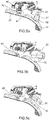
- the figures 5a, 5b and 5c show the fairlead 20 in profile in different positions of the automatic opening mechanisms associated with each sector 23 and 24.
- the bolt 30 and the force sensor 32 of the sector 24 can be distinguished as well as a bolt 40 and a sensor effort 42 associated with sector 23.
- bolts 30 and 40 are closed, on the figure 5b the bolts 30 and 40 are open so as to allow fish 12 to pass towards the sea and on the figure 5c the bolts 30 and 40 are open so as to allow the fish 12 to pass towards the winch 16.
- the bolts are movable in rotation about an axis, 31 for the bolt 30 and about an axis 41 for the bolt 40.
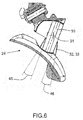
- the figure 6 shows in more detail the sector 24 and its automatic opening mechanism.
- the force sensor 32 comprises a tongue 33 movable in rotation around the axis of rotation 31.
- the force sensor 32 makes it possible to detect a force in front of the bolt 30 in the direction of movement considered for the cable 14. Otherwise Said, when one of the arms 12a or 12b approaches the automatic opening mechanism, contact is made with the tongue 33 which is located in front of the bolt 30. Thus, no contact is made with the bolt 30 itself. Indeed, such a contact could interfere with its opening and cause damage to the bolt 30 and the arm 12a or 12b. On the figure 6 one distinguishes the advance of the tongue 33 in the two possible directions of movement of the cable 14.
- the advance is for example angular of ten degrees: advance 45 when the fish 12 crosses the fairlead 20 towards the sea and advance 46 when the fish 12 passes through the fairlead 20 towards the winch 16.
- advance 45 when the fish 12 crosses the fairlead 20 towards the sea
- advance 46 when the fish 12 passes through the fairlead 20 towards the winch 16.
- Other forms of tabs 33 are also possible and the feed rate can be defined linearly.
- the automatic opening mechanism of the sector 23 is made similarly to the mechanism of the sector 24 with its advances in the two directions of circulation of the cable 14 in the fairlead 20.
- the figure 7 shows the automatic opening mechanism in section through the axis 31.
- the trigger 36 is located inside a bell 50 integral with the tongue 33.
- the trigger 36 mainly comprises a pawl 52 which can take three positions: a position where the bolt 30 is closed as shown in Figure figure 5a and two open positions where the bolt 30 is open as shown in the figure 5b and 5c .
- the closed position is effective without effort on the tongue 33 and the open positions are reached when a force greater than a predetermined force in one of the two directions carried by the main direction 27 is exerted on the tongue 33.
- the pawl 52 may not have only one open position if a pressing force on the tongue 33 is detected only in one direction.
- the pawl 52 is also visible on the sections HH and DD shown on the figures 8 and 9 .
- the section planes HH and DD are perpendicular to the axis 31 and their position is identified on the figure 7 .
- the automatic opening mechanism has a shaft 54 extending along the axis 31.
- the shaft is fixed to the bolt 30 not shown in the figure. figure 7 .
- One of the ends 56 of the shaft 54 can be splined to ensure that the mechanism is positioned with the bolt 30.
- the mechanism and the bolt 30 can be held in position by means of an internal thread 58. Any other means of positioning and maintaining in position is of course possible.
- the mechanism comprises a frame 60 fixed to the sector 24.
- the bolt 30 and the tongue 33 are movable in rotation about the axis 31 relative to the frame 60 and therefore relative to the sector 24.
- the pawl 52 comprises two fingers 61 and 62 movable in rotation relative to the frame 60 about an axis 64.
- the fingers each have a hook: 65 for the finger 61 and 66 for the finger 62.
- the hooks 65 and 66 come into abutment against the shaft 54.
- the pawl 52 comprises a spring 68 holding the two fingers 61 and 62 in abutment on the shaft 54.
- the hooks 65 and 66 can come into abutment directly against the shaft 54 or advantageously against a cam 67 linked to the shaft by screws 69 forming mechanical fuses.
- the cam 67 and the shaft 54 are integral with one another.
- the screws 69 may break and release the cam 67 which can then rotate relative to the shaft 54.
- a failure may for example be due to a sticking of the fingers 65 and 66 against them. the cam 67 preventing the opening of the bolt 30, even if the force on the force sensor exceeds the predetermined threshold for opening.
- a pin 70 integral with the tongue 33, allows the pawl 52 to be opened by moving one of the fingers 61 and 62 apart.
- the pin 70 is fixed to the bell. 50 which itself is attached to the tab 33.
- a first spring 72 opposes the rotation of the tongue 33 relative to the bolt 30 which in the closed position of the pawl 52 is fixed.
- the internal shape of the fingers 61 and 62 on which the pin 70 rests as well as the shape of the hooks 65 and 66 are configured to define the force beyond which the pawl 52 opens to release the bolt 30.
- the figure 9a is an enlarged part of the figure 9 where one distinguishes the shape of the fingers 61 and 62 in the vicinity of the point of equilibrium where no force is exerted on the tongue 33.
- the internal shape of the finger is substantially flat so as not to induce any movement of the finger 62.
- This flat zone is marked 76.
- the pin 70 reaches an inclined shoulder 78 forcing the finger 62 to move away from the shaft 54.
- the hook 66 is released from its stop. It is during the passage of this shoulder that the bolt 30 is released.
- the pin 70 reaches a substantially circular zone 80 around the shaft 54. In this zone, the hook 66 is kept at a distance from its stop.
- the internal shapes of the other finger 61 are for example symmetrical.
- Asymmetrical shapes are possible, in particular to offset the feed in one direction with respect to the other or to obtain different forces that must be applied by one of the arms 12a or 12b of the fish 12 in one direction and the other.
- a difference in force can be useful because on the descent towards the sea, only the drag of the streamer 13 drives the fish while during the ascent of the fish, the winch 16 can exert a greater force.
- the fish 12, the fairlead 20 and therefore the tongue 33 are likely to receive sea packets. Consequently, it is useful to differentiate the predetermined force values to be exerted on the tongue 33 for open the bolt 30 to the ascent of the fish 12, corresponding to the direction 34 and to the descent of the fish corresponding to the opposite direction.
- the predetermined force value for the direction 34 is therefore advantageously greater than the predetermined force value for the reverse direction.
- the mechanism comprises a second spring 74 connected between the frame 60 and the first spring 72 and tending to close the bolt 30 which is integral with the common point between the two springs 72 and 74.
- a stiffness of the second spring 74 less than that of the first spring 72, it is possible at the same time to limit the force necessary for the complete opening of the mechanism and at the same time to maintain a significant triggering force of the pawl 52 and therefore to maintain the minimum force to be exceeded for trigger the opening of the bolt 30.
- the two springs 72 and 74 are preloaded so as to allow the return to the closed position when the pressure on the tongue 33 ceases. It is possible to adjust the preload and the stiffness of the spring 74 to a value lower than that of the spring 72 in order to further reduce the force required to reach the open position of the bolt 30.
- the spring 74 is pre-stressed between two flanges 82 and 84 which are free to rotate with respect to the frame 60 each in an angular sector giving the possible angular travel for the bolt 30 for one of the directions of rotation.
- the equilibrium position is visible on the figure 9 where the flange 82 is in abutment against a key 86 fixed to the frame 60.
- the flange 82 comprises a free angular sector 88 allowing it to rotate relative to the frame 60 during the rotation of the bolt 30 in one of the directions of rotation.
- the maximum rotation of the bolt 30 is 110 °.
- a maximum rotation value of the order of 90 ° or slightly greater allows the bolt 30 to retract sufficiently during the passage of the arms of the fish 12.
- the flange 84 comprises a similar angular sector allowing the rotation of the bolt 30 in the other direction of rotation.
- the free angular sectors of the flanges 82 and 84 may be different depending on the maximum strokes desired for the bolt 30 in its two directions of rotation.
- the spring 72 it is possible to split the spring 74 in order to distinguish both the stiffness and the preload in the two directions of circulation of the cable 14 in the fairlead 20.
- the figure 10 shows in the form of a curve the force applied to the tongue 33 as a function of the displacement of the latter in one of the directions carried by the main direction 27.
- the springs 72 and 74 are, in the variant shown, torsion springs , the force is given in the form of a torque denoted C.
- the tongue 33 moving in rotation its displacement is expressed as an angle denoted a.
- a functional clearance a1 for example of about 1 ° is provided between the cam 67 and the pawl 52, more precisely, between the fingers 65 and 66 and the cam 67. This play makes it possible to ensure the return of the pawl 52 in the closed position. and therefore the bolt 30 in the closed position.
- a couple C1 represents the preload of the spring 74.
- the functional play a1 is taken up by a tension of the spring 74.
- the pawl 52 bears on the cam 67 and the torque required for a rotation of the tongue 33 is the preload torque C2 of the spring 72 which is greater than the torque C1, hence the vertical part of the curve between the pairs C1 and C2 for the angular position a1.
- the pin 70 traverses the flat area 76 and the spring 72 stretches from a preload C2 until it reaches a position a2, for example of the order of 2.5 °. In this position, the pin 70 comes into contact with the shoulder 78.
- the slope of the curve between the positions a1 and a2 is essentially given by the stiffness of the spring 72. Then the pin 70 moves on the shoulder 78 and the curve becomes substantially vertical to reach the predetermined triggering force C5 to be exceeded in order to release the rotation of the bolt 30 and thus allow its opening.
- the force C5 is for example reached for an angular position a3 of 3 °, which is less than the advance of the tongue 33 relative to the bolt 30. This advance is shown on the diagram. figure 10 by an angular position a4 for example of the order of 10 °.
- the bolt 30 opens before the object (in this case the fish) which has triggered its opening reaches it.
- the tongue 33 moves angularly without the bolt 30 turning.
- the latter realigns itself with the tongue 33.
- the stiffness of the spring 72 contributes to the realignment of the bolt 30 with the tongue 33.
- the curve of the figure 10 After opening the bolt 30, the curve of the figure 10 returns to a lower value and follows a moderate slope given by the stiffness of the second spring 74.
- the descent of the curve is due to the transition between the zones 78 and 80 of the finger 62 as well as to the release of the hook 66 which rubbed against its stop on the shaft 54.
- the preload C1 of the second spring 74 is, in the example shown, lower than the preload C2 of the first spring 72.
- the variant with only one spring (per direction) is also shown in dotted lines on the figure 10 .
- the single spring stretches until it reaches a torque C6 for position a5.
- the torque C6 results from the stiffness of the single spring and the minimum torque C5 desired for the torque at the opening of the mechanism at position a3.
- the single spring variant results in a much higher C6 value than the value C3 if the stiffness of the spring is important. It is possible to choose, for this single spring, a lower stiffness (less pronounced slope for the dotted curve) but this requires a very significant increase in size.
- the curve is substantially symmetrical with respect to the y-axis except for the adaptations described above, value of the maximum torque C5 and angular amplitude which can be adjusted differently in the two directions of rotation.
- the bolt 30 tends to return to its closed equilibrium position regardless of its direction of rotation.
- the return of the tongue 33 relative to the shaft 54 is effected in a manner similar to that of the bolt 30 relative to the frame 60.
- the spring 72 is prestressed between two flanges 90 and 92 movable in rotation relative to the shaft. 54.
- the flange 90 is coupled to the shaft 54 via a key and the flange 92 is coupled to the bell 50 and therefore to the tongue 33 via a pin.
- the angular movement of the flange 90 is approximately 10 ° relative to the shaft 54, it corresponds to the advance 45 and 46 of the tongue 33 relative to the bolt 30, it can be ensured as before by means of a key fixed to the shaft 54 and a free angular sector produced in the flange 90.
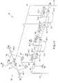
- the figure 11 shows a kinematic diagram of the first embodiment.
- this diagram some variants have been shown compared to the cross-sectional representations of figures 7 to 9 .
- the spring 68 has been replaced by two springs 68.1 and 68.2.
- the spring 68.1 is arranged between the finger 61 and the frame 60.
- the spring 68.1 tends to bring the finger 61 back to bear against the shaft 54.
- the spring 68.2 is disposed between the finger 62 and the frame 60.
- the spring 68.2 tends to bring the finger 62 back to bear against the shaft 54.
- This doubling of the spring 68 makes it possible to differentiate the force required to open the pawl 32 in both directions.
- the pin 70 integral with the bell 50 and the tongue 33 appears on the diagram of the figure 11 .
- the contact that the pin 70 can exert on one of the fingers 61 or 62 is represented in the form of a rectilinear linear connection.
- a one-off connection is also possible. It is understood that the pin 70 exerts only one contact at a time, either on the finger 61 or on the finger 62. Consequently, only one of the rectilinear linear links is effective at a time, the other being absent.
- the springs 72 and 74 have also been split as mentioned above.
- the function provided by the spring 72 is provided by the spring 72.1 held between the two flanges 90.1 and 92.1.
- the function performed by the spring 72 is performed by the spring 72.2 held between the two flanges 90.2 and 92.2.
- the function provided by the spring 74 is provided by the spring 74.1 held between the two flanges 82.1 and 84.1.
- the function performed by the spring 74 is performed by the spring 74.2 held between the two flanges 82.2 and 84.2.
- the key 86 integral with the frame 60 is also split and shown on the figure 11 .
- the flange 82.1 bears against the key 86.1.
- the flange 82.2 bears against the key 86.2.
- These supports are shown schematically in the form of rectilinear linear connections that it is possible to lose when the corresponding flange rotates relative to the shaft 54, as for example in the free angular sector 88 for the flange 82 as visible on the figure. figure 9 .
- Simple point links can also replace the various rectilinear linear links.
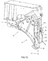
- the figure 12 shows in perspective a second embodiment of an automatic fairlead opening mechanism 20. There are two sectors 23 and 24. It is understood that this second embodiment can be implemented in a fairlead with only one sector.
- the tongue 33 making it possible to detect a force.
- a bolt 100 which, unlike the first embodiment, opens and closes in a translational movement along an axis 102.
- the bolt is guided in translation with respect to the sector 24 along the axis 102.
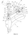
- the figure 13 shows a side view of the automatic opening mechanism of the second embodiment.
- the tongue 33 is, as above, movable in rotation about the axis 31 relative to the sector 24.
- the force sensor 32 makes it possible to detect a force in front of the bolt 30 in the direction of movement considered for the. cable 14.
- This advance is clearly visible on the figure 12 where the tongue 33 projects from the bolt 100 in at least one of the directions carried by the main direction 27 followed by the cable 14 in the sector 24.
- the tongue 33 protrudes from the bolt 100 in both directions.
- the outer shape of the tongue 33 on which the arms of the fish 12 are intended to rest makes it possible to define the advance relative to the bolt 100.
- a pinion 104 is integral with the tongue 33.
- the pinion 104 rotates around the axis 31.
- a second pinion 106 is movable in rotation with respect to the sector 24.
- the axis of rotation 108 of the pinion 106 is distinct from the axis of rotation 31 of the pinion 104.
- the pinion 106 is driven by the pinion 104 by means of a belt 110.
- the tongue 33, the pinions 104 and 106 as well as the belt fulfill the function of the force sensor 32.
- a cam 112 is integral with the pinion 106.
- An arm 114 can pivot at one of its ends 116 relative to the sector 24 about an axis 118 separate from the axes of rotation 31 and 108 of the two pinions 104 and 106.
- the arm 114 comprises a roller 120 forming a cam follower and resting on the cam 112.
- the bolt 100 comprises a pin 122 which can slide in a groove 124 made in the arm 114 at its second end 126.
- the cam 112, the arm 114 and the roller 120 perform the function of trigger 36.
- the arm 114 forms a lever making it possible to translate the bolt 100 along its axis 102.
- the shape of the cam 112 is defined to coordinate the translational movement of the bolt 100 as a function of the angular displacement of the tongue 33.
- the distance ratio between on the one hand, the pin 122 and the axis of rotation 118 and on the other hand the roller 120 and the axis of rotation 118 make it possible to amplify the translation of the bolt 100 relative to the rotation of the tongue 33.
- This amplification can be modified by the ratio of the diameters of the pinions 104 and 106.
- the pinions 104 and 106 as well as the arm 114 amplify the translational movement of the bolt 100. A reduction is also possible.
- any other means for transforming the rotational movement of the tongue 33 into a translational movement of the bolt 100 is possible within the framework of the invention, such as for example a system of the connecting rod-crank type.
- the latter advantageously comprises a groove 130 in which the roller 120 moves. The roller 120 then remains in contact with the two sides of the groove 130.
- the profile of the cam 112 on which the roller 120 rests is advantageously defined so that the mechanism is irreversible, that is to say that a force on the bolt 100 cannot open it. This makes it possible to prevent the friction of the cable on the bolt 100 from being able to make it go up. Thus only a force on the tongue 33 tending to make it pivot about its axis 31 makes it possible to open the bolt 100.
- the profile of the cam 112 is symmetrical with respect to the point of equilibrium shown on the figure 13 . This point of equilibrium corresponds to the low position of the bolt 100 where it closes the sector 24.
- the symmetrical shape of the cam 112 allows identical movements of the bolt 100 according to the rotation of the tongue 33 in both directions carried by the direction 27. It is possible to provide different shapes for each of the two directions as a function of the desired movements for the bolt 100.
- the mechanism comprises a return spring 132 tending to keep the bolt 100 in the closed position.
- a preload of the spring 132 makes it possible to define the minimum force to be exerted on the tongue 33 to open the bolt 100.
- the spring 132 can be directly fixed between the sector 24 and the bolt 100. This arrangement of the spring 132 only works if the mechanism is reversible. In the case of an irreversible mechanism, the spring 132 can be directly fixed between the sector 24 and the cam 112 in order to exert a torque on the cam 112, this torque tending to maintain the roller 120 in the equilibrium position. .
- the mechanism comprises a ring 134 movable in rotation relative to the sector 24 and a pinion 136 integral with the cam 112.
- the ring 134 and the pinion 136 roll without slide over each other.
- the crown 134 and the pinion 136 comprise, for example, cooperating gear teeth.
- the pinion 136 is located behind the cam 112, while the pinion 106 is located in front of the cam 112.
- the spring 132 is fixed between the sector 24 and the crown 134.
- the diameter ratio between the pinion 136 and the crown 134 amplifies the return force of the spring 132.
Landscapes
- Chemical & Material Sciences (AREA)
- Engineering & Computer Science (AREA)
- Combustion & Propulsion (AREA)
- Mechanical Engineering (AREA)
- Ocean & Marine Engineering (AREA)
- Transmission Devices (AREA)
- Measurement Of Velocity Or Position Using Acoustic Or Ultrasonic Waves (AREA)
- Catching Or Destruction (AREA)
Claims (14)
- Seilführung, dazu bestimmt, eine Schleppvorrichtung auszurüsten, installierbar auf der Brücke eines Schiffs (10) und umfassend eine Winde (16), ein Seil (14), welches unter Einwirkung der Winde (16) durch die Seilführung (20) läuft, wobei die Seilführung (20) einen Kanal (24) mit offenem Abschnitt umfasst, welcher sich in eine Hauptrichtung (27) erstreckt, um das Seil (14) zu führen, dadurch gekennzeichnet, dass die Seilführung (20) Folgendes umfasst:• einen beweglichen Riegel (30, 40, 100), welcher einen Abschnitt des Kanals (24) verschließt,• einen Kraftsensor (32), welcher vor dem Riegel (30, 40, 100) befindlich ist, in einer Richtung (34) der Hauptrichtung (27), und konfiguriert ist, um eine äußere Kraft zu detektieren, und• einen Auslöser (36), welcher zum Öffnen des Riegels (30, 40, 100) konfiguriert ist, wenn die auf den Sensor (32) ausgeübte und entlang der Hauptrichtung (27) in die Richtung (34) ausgerichtete Kraft eine vorbestimmte Kraft überschreitet und zum verschließen des Riegels (30, 40, 100), wenn diese Kraft verschwindet.
- Seilführung nach Anspruch 1, dadurch gekennzeichnet, dass der Kraftsensor (32) zum Detektieren einer äußeren Kraft vor dem Riegel (30, 40, 100) in beiden durch die Hauptrichtung (27) getragenen Richtungen konfiguriert ist, und der Auslöser (36) zum Öffnen des Riegels (30, 40, 100) konfiguriert ist, wenn eine auf den Sensor (32) ausgeübte und entlang der Hauptrichtung (27) in beide Richtungen ausgerichtete Kraft die vorbestimmte Kraft überschreitet und zum Verschließen des Riegels (30, 40, 100), wenn diese Kraft verschwindet.
- Seilführung nach einem der vorhergehenden Ansprüche, dadurch gekennzeichnet, dass der Riegel (30, 40) drehbar in Bezug auf den Kanal (24) um eine Rotationsachse (31) beweglich ist, welche im Wesentlichen rechtwinklig zur Hauptrichtung (27) ist.
- Seilführung nach Anspruch 3, dadurch gekennzeichnet, dass der Kraftsensor (32) eine drehbar um eine Rotationsachse (31) bewegliche Zunge (33) umfasst, dass der Auslöser (36) eine Klinke (52) umfasst, welche zwei Positionen einnehmen kann, deren erste Position, genannt geschlossene Position, effektiv ist wenn keine Kraft auf die Zunge (33) einwirkt, und deren zweite Position, genannt geöffnete Position, freies Drehen des Riegels (30, 40) zulässt, und dadurch, dass die Klinke (52) durch die Zunge (33) von der geschlossenen in die geöffnete Position angetrieben wird, nach Überschreitung der vorbestimmten Kraft, wobei die Seilführung zudem eine erste Feder (72) umfasst, welche zwischen dem Kanal (24) und der Zunge (33) verbunden ist, wobei die Steife der Feder (72) zu der vorbestimmten Kraft und zur Wiederausfluchtung des Riegels (30) mit der Zunge (33) beiträgt.
- Seilführung nach Anspruch 4, dadurch gekennzeichnet, dass die erste Feder (72) vorgespannt ist, wobei die Vorspannung zu der vorbestimmten Kraft und zur Wiederausfluchtung des Riegels (30) mit der Zunge (33) beiträgt.
- Seilführung nach einem der Ansprüche 4 oder 5, dadurch gekennzeichnet, dass der Auslöser (36) eine zweite Feder (74) umfasst, welche zum verschließen des Riegels (30, 40) tendiert, wobei die zweite Feder (74) in Reihe mit der ersten Feder (72) verbunden ist, dadurch, dass der Riegel (30) fest mit dem gemeinsamen Punkt zwischen den beiden Federn (72, 74) verbunden ist.
- Seilführung nach Anspruch 6, dadurch gekennzeichnet, dass die zweite Feder (74) eine Steife kleiner als die der ersten Feder (72) besitzt.
- Seilführung nach einem der Ansprüche 6 oder 7, dadurch gekennzeichnet, dass die zweite Feder (74) um einen Wert kleiner als der der ersten Feder (72) vorgespannt ist.
- Seilführung nach einem der Ansprüche 1 oder 2, dadurch gekennzeichnet, dass der Riegel (100) verschiebbar in Bezug auf den Kanal entlang einer Achse (102) beweglich ist, welche im Wesentlichen rechtwinklig zur Hauptrichtung (27) ist.
- Seilführung nach Anspruch 9, dadurch gekennzeichnet, dass der Kraftsensor (32) eine drehbar um eine Rotationsachse (31) bewegliche Zunge (33) umfasst, welche im Wesentlichen rechtwinklig zur Hauptrichtung (27) ist und Mittel zum Umwandeln einer Drehbewegung der Zunge (33) in eine Verschiebung des Riegels (100).
- Seilführung nach Anspruch 10, dadurch gekennzeichnet, dass die Mittel zum Umwandeln einer Drehbewegung der Zunge (33) in eine Verschiebung des Riegels (100) nicht umkehrbar sind.
- Seilführung nach einem der Ansprüche 10 oder 11, dadurch gekennzeichnet, dass sie eine mit der Zunge (33) drehende Nocke (112) und einen schwenkbaren Hebel (114), welcher entfernt von seiner Schwenkachse (118) einen Stift (120) umfasst, welcher sich auf die Nocke (112) stützt und eine Nut (124), in welche sich der Riegel (100) stützt, umfasst.
- Seilführung nach Anspruch 12, dadurch gekennzeichnet, dass sie eine Rückstellfeder (132) umfasst, welche dazu tendiert, die Nocke (112) in eine Gleichgewichtsposition zurückzubringen, in welcher der Riegel (100) geschlossen ist.
- Schleppvorrichtung, welche auf der Brücke eines Schiffs (10) installiert werden kann und eine Winde (16), ein Seil (14) und eine Seilführung (20) nach einem der vorhergehenden Ansprüche umfasst, wobei die Seilführung (20) und die Winde (16) in Bezug aufeinander fest sind.
Applications Claiming Priority (2)
| Application Number | Priority Date | Filing Date | Title |
|---|---|---|---|
| FR1601450A FR3057241B1 (fr) | 2016-10-06 | 2016-10-06 | Chaumard a ouverture automatique et dispositif de remorquage comprenant le chaumard |
| PCT/EP2017/075034 WO2018065385A1 (fr) | 2016-10-06 | 2017-10-03 | Chaumard a ouverture automatique et dispositif de remorquage comprenant le chaumard |
Publications (2)
| Publication Number | Publication Date |
|---|---|
| EP3523190A1 EP3523190A1 (de) | 2019-08-14 |
| EP3523190B1 true EP3523190B1 (de) | 2020-11-25 |
Family
ID=57906664
Family Applications (1)
| Application Number | Title | Priority Date | Filing Date |
|---|---|---|---|
| EP17777057.5A Active EP3523190B1 (de) | 2016-10-06 | 2017-10-03 | Selbstöffnende seilführung und schleppvorrichtung mit der seilführung |
Country Status (5)
| Country | Link |
|---|---|
| US (1) | US10766574B2 (de) |
| EP (1) | EP3523190B1 (de) |
| AU (1) | AU2017338287B2 (de) |
| FR (1) | FR3057241B1 (de) |
| WO (1) | WO2018065385A1 (de) |
Families Citing this family (3)
| Publication number | Priority date | Publication date | Assignee | Title |
|---|---|---|---|---|
| FR3101848B1 (fr) | 2019-10-10 | 2022-01-28 | Thales Sa | Dispositif sous-marin remorque et systeme de manutention du dispositif sous-marin |
| FR3135695B1 (fr) | 2022-05-19 | 2024-04-19 | Thales Sa | Dispositif sous-marin remorqué |
| CN118928645A (zh) * | 2024-08-26 | 2024-11-12 | 中船黄埔文冲船舶有限公司 | 导缆装置以及船舶 |
Family Cites Families (9)
| Publication number | Priority date | Publication date | Assignee | Title |
|---|---|---|---|---|
| US3347526A (en) * | 1966-11-16 | 1967-10-17 | Cymmer Thomas | Guide for faired cable |
| GB1522131A (en) * | 1975-07-29 | 1978-08-23 | British Petroleum Co | Launching towing and recovery apparatus |
| US4658750A (en) * | 1983-03-14 | 1987-04-21 | Columbia Gas System Service Corp. | Apparatus and method for detecting gas bubbles in water, and apparatus for handling an oceanographic device |
| CA1202828A (en) * | 1983-07-15 | 1986-04-08 | Robert S. Norminton | Compact towing system for underwater bodies |
| JP2001354189A (ja) * | 2000-06-09 | 2001-12-25 | Hitachi Zosen Corp | 水中曳航体の投入揚収装置及びその巻取り装置 |
| US8087372B1 (en) * | 2010-04-01 | 2012-01-03 | The United States Of America As Represented By The Secretary Of The Navy | Fairlead for a tow cable handling system |
| FR2982579B1 (fr) * | 2011-11-10 | 2015-12-25 | Thales Sa | Dispositif de remorquage a chaumard articule |
| FR3009271B1 (fr) * | 2013-08-02 | 2016-11-04 | Thales Sa | Dispositif de remorquage a chaumard en deux parties |
| CN104816806B (zh) * | 2015-05-04 | 2017-03-01 | 大连理工大学 | 一种大型水下组合拖曳装置及其使用方法 |
-
2016
- 2016-10-06 FR FR1601450A patent/FR3057241B1/fr not_active Expired - Fee Related
-
2017
- 2017-10-03 WO PCT/EP2017/075034 patent/WO2018065385A1/fr not_active Ceased
- 2017-10-03 AU AU2017338287A patent/AU2017338287B2/en active Active
- 2017-10-03 US US16/340,093 patent/US10766574B2/en active Active
- 2017-10-03 EP EP17777057.5A patent/EP3523190B1/de active Active
Non-Patent Citations (1)
| Title |
|---|
| None * |
Also Published As
| Publication number | Publication date |
|---|---|
| FR3057241B1 (fr) | 2018-11-30 |
| US10766574B2 (en) | 2020-09-08 |
| EP3523190A1 (de) | 2019-08-14 |
| WO2018065385A1 (fr) | 2018-04-12 |
| AU2017338287A1 (en) | 2019-05-23 |
| FR3057241A1 (fr) | 2018-04-13 |
| US20200047853A1 (en) | 2020-02-13 |
| AU2017338287B2 (en) | 2023-01-19 |
| CA3039548A1 (en) | 2018-04-12 |
Similar Documents
| Publication | Publication Date | Title |
|---|---|---|
| EP3027498B1 (de) | Schleppvorrichtung mit zweiteiliger klüse | |
| EP3523190B1 (de) | Selbstöffnende seilführung und schleppvorrichtung mit der seilführung | |
| EP2885202B1 (de) | Vorrichtung zum aussetzen und bergen eines geschleppten sonars | |
| FR2925231A1 (fr) | Antenne sonar d'emission a axe vertical enroulable sur un treuil | |
| EP2776309B1 (de) | Schleppvorrichtung mit einer schwenkbarem klüse | |
| WO2015071318A1 (fr) | Chaumard de guidage d'un élément d'ancrage | |
| EP3976461B1 (de) | Unterwasservorrichtung und unterwassersystem | |
| EP3729144B1 (de) | Schleppsensor mit variablem hydrodynamischem auftrieb und schlepptau mit dem schleppsensor | |
| FR2519062A1 (fr) | Dispositif de mise en tension d'une toile de store a rouleau | |
| EP4041625B1 (de) | Geschleppte unterwasservorrichtung und system zur handhabung der unterwasservorrichtung | |
| EP3976460B1 (de) | Sonarvorrichtung und sonarsystem | |
| EP3261912B1 (de) | Abschleppanlage | |
| FR2923452A1 (fr) | Dispositif retourneur d'ecailles notamment pour cable tracteur carene comportant de telles ecailles | |
| EP4526201B1 (de) | Gezogenes unterwassergerät | |
| EP3261914B1 (de) | Ummantelung eines schleppkabels | |
| CA3039548C (en) | Automatic-opening fairlead and towing device comprising the fairlead | |
| FR3134793A1 (fr) | Dispositif d’amarrage à tourelle externe et navire comportant un tel dispositif d’amarrage à tourelle externe. | |
| WO2020120544A2 (fr) | Câble tracteur caréné | |
| EP3740425A1 (de) | Boot mit einem drachen | |
| FR2966422A1 (fr) | Navire comprenant un dispositif de nettoyage et un dispositif de guidage d'objets flottants tels que des hydrocarbures |
Legal Events
| Date | Code | Title | Description |
|---|---|---|---|
| STAA | Information on the status of an ep patent application or granted ep patent |
Free format text: STATUS: UNKNOWN |
|
| STAA | Information on the status of an ep patent application or granted ep patent |
Free format text: STATUS: THE INTERNATIONAL PUBLICATION HAS BEEN MADE |
|
| PUAI | Public reference made under article 153(3) epc to a published international application that has entered the european phase |
Free format text: ORIGINAL CODE: 0009012 |
|
| STAA | Information on the status of an ep patent application or granted ep patent |
Free format text: STATUS: REQUEST FOR EXAMINATION WAS MADE |
|
| 17P | Request for examination filed |
Effective date: 20190411 |
|
| AK | Designated contracting states |
Kind code of ref document: A1 Designated state(s): AL AT BE BG CH CY CZ DE DK EE ES FI FR GB GR HR HU IE IS IT LI LT LU LV MC MK MT NL NO PL PT RO RS SE SI SK SM TR |
|
| AX | Request for extension of the european patent |
Extension state: BA ME |
|
| DAV | Request for validation of the european patent (deleted) | ||
| DAX | Request for extension of the european patent (deleted) | ||
| GRAP | Despatch of communication of intention to grant a patent |
Free format text: ORIGINAL CODE: EPIDOSNIGR1 |
|
| STAA | Information on the status of an ep patent application or granted ep patent |
Free format text: STATUS: GRANT OF PATENT IS INTENDED |
|
| INTG | Intention to grant announced |
Effective date: 20200604 |
|
| GRAJ | Information related to disapproval of communication of intention to grant by the applicant or resumption of examination proceedings by the epo deleted |
Free format text: ORIGINAL CODE: EPIDOSDIGR1 |
|
| STAA | Information on the status of an ep patent application or granted ep patent |
Free format text: STATUS: REQUEST FOR EXAMINATION WAS MADE |
|
| GRAP | Despatch of communication of intention to grant a patent |
Free format text: ORIGINAL CODE: EPIDOSNIGR1 |
|
| STAA | Information on the status of an ep patent application or granted ep patent |
Free format text: STATUS: GRANT OF PATENT IS INTENDED |
|
| GRAS | Grant fee paid |
Free format text: ORIGINAL CODE: EPIDOSNIGR3 |
|
| INTC | Intention to grant announced (deleted) | ||
| INTG | Intention to grant announced |
Effective date: 20200915 |
|
| GRAA | (expected) grant |
Free format text: ORIGINAL CODE: 0009210 |
|
| STAA | Information on the status of an ep patent application or granted ep patent |
Free format text: STATUS: THE PATENT HAS BEEN GRANTED |
|
| AK | Designated contracting states |
Kind code of ref document: B1 Designated state(s): AL AT BE BG CH CY CZ DE DK EE ES FI FR GB GR HR HU IE IS IT LI LT LU LV MC MK MT NL NO PL PT RO RS SE SI SK SM TR |
|
| REG | Reference to a national code |
Ref country code: GB Ref legal event code: FG4D Free format text: NOT ENGLISH |
|
| REG | Reference to a national code |
Ref country code: CH Ref legal event code: EP |
|
| REG | Reference to a national code |
Ref country code: DE Ref legal event code: R096 Ref document number: 602017028383 Country of ref document: DE |
|
| REG | Reference to a national code |
Ref country code: AT Ref legal event code: REF Ref document number: 1337985 Country of ref document: AT Kind code of ref document: T Effective date: 20201215 |
|
| REG | Reference to a national code |
Ref country code: IE Ref legal event code: FG4D Free format text: LANGUAGE OF EP DOCUMENT: FRENCH |
|
| REG | Reference to a national code |
Ref country code: AT Ref legal event code: MK05 Ref document number: 1337985 Country of ref document: AT Kind code of ref document: T Effective date: 20201125 |
|
| REG | Reference to a national code |
Ref country code: NL Ref legal event code: MP Effective date: 20201125 |
|
| PG25 | Lapsed in a contracting state [announced via postgrant information from national office to epo] |
Ref country code: RS Free format text: LAPSE BECAUSE OF FAILURE TO SUBMIT A TRANSLATION OF THE DESCRIPTION OR TO PAY THE FEE WITHIN THE PRESCRIBED TIME-LIMIT Effective date: 20201125 Ref country code: PT Free format text: LAPSE BECAUSE OF FAILURE TO SUBMIT A TRANSLATION OF THE DESCRIPTION OR TO PAY THE FEE WITHIN THE PRESCRIBED TIME-LIMIT Effective date: 20210325 Ref country code: FI Free format text: LAPSE BECAUSE OF FAILURE TO SUBMIT A TRANSLATION OF THE DESCRIPTION OR TO PAY THE FEE WITHIN THE PRESCRIBED TIME-LIMIT Effective date: 20201125 Ref country code: GR Free format text: LAPSE BECAUSE OF FAILURE TO SUBMIT A TRANSLATION OF THE DESCRIPTION OR TO PAY THE FEE WITHIN THE PRESCRIBED TIME-LIMIT Effective date: 20210226 Ref country code: NO Free format text: LAPSE BECAUSE OF FAILURE TO SUBMIT A TRANSLATION OF THE DESCRIPTION OR TO PAY THE FEE WITHIN THE PRESCRIBED TIME-LIMIT Effective date: 20210225 |
|
| PG25 | Lapsed in a contracting state [announced via postgrant information from national office to epo] |
Ref country code: BG Free format text: LAPSE BECAUSE OF FAILURE TO SUBMIT A TRANSLATION OF THE DESCRIPTION OR TO PAY THE FEE WITHIN THE PRESCRIBED TIME-LIMIT Effective date: 20210225 Ref country code: SE Free format text: LAPSE BECAUSE OF FAILURE TO SUBMIT A TRANSLATION OF THE DESCRIPTION OR TO PAY THE FEE WITHIN THE PRESCRIBED TIME-LIMIT Effective date: 20201125 Ref country code: IS Free format text: LAPSE BECAUSE OF FAILURE TO SUBMIT A TRANSLATION OF THE DESCRIPTION OR TO PAY THE FEE WITHIN THE PRESCRIBED TIME-LIMIT Effective date: 20210325 Ref country code: PL Free format text: LAPSE BECAUSE OF FAILURE TO SUBMIT A TRANSLATION OF THE DESCRIPTION OR TO PAY THE FEE WITHIN THE PRESCRIBED TIME-LIMIT Effective date: 20201125 Ref country code: LV Free format text: LAPSE BECAUSE OF FAILURE TO SUBMIT A TRANSLATION OF THE DESCRIPTION OR TO PAY THE FEE WITHIN THE PRESCRIBED TIME-LIMIT Effective date: 20201125 Ref country code: AT Free format text: LAPSE BECAUSE OF FAILURE TO SUBMIT A TRANSLATION OF THE DESCRIPTION OR TO PAY THE FEE WITHIN THE PRESCRIBED TIME-LIMIT Effective date: 20201125 |
|
| REG | Reference to a national code |
Ref country code: LT Ref legal event code: MG9D |
|
| PG25 | Lapsed in a contracting state [announced via postgrant information from national office to epo] |
Ref country code: HR Free format text: LAPSE BECAUSE OF FAILURE TO SUBMIT A TRANSLATION OF THE DESCRIPTION OR TO PAY THE FEE WITHIN THE PRESCRIBED TIME-LIMIT Effective date: 20201125 |
|
| PG25 | Lapsed in a contracting state [announced via postgrant information from national office to epo] |
Ref country code: RO Free format text: LAPSE BECAUSE OF FAILURE TO SUBMIT A TRANSLATION OF THE DESCRIPTION OR TO PAY THE FEE WITHIN THE PRESCRIBED TIME-LIMIT Effective date: 20201125 Ref country code: SK Free format text: LAPSE BECAUSE OF FAILURE TO SUBMIT A TRANSLATION OF THE DESCRIPTION OR TO PAY THE FEE WITHIN THE PRESCRIBED TIME-LIMIT Effective date: 20201125 Ref country code: SM Free format text: LAPSE BECAUSE OF FAILURE TO SUBMIT A TRANSLATION OF THE DESCRIPTION OR TO PAY THE FEE WITHIN THE PRESCRIBED TIME-LIMIT Effective date: 20201125 Ref country code: EE Free format text: LAPSE BECAUSE OF FAILURE TO SUBMIT A TRANSLATION OF THE DESCRIPTION OR TO PAY THE FEE WITHIN THE PRESCRIBED TIME-LIMIT Effective date: 20201125 Ref country code: CZ Free format text: LAPSE BECAUSE OF FAILURE TO SUBMIT A TRANSLATION OF THE DESCRIPTION OR TO PAY THE FEE WITHIN THE PRESCRIBED TIME-LIMIT Effective date: 20201125 Ref country code: LT Free format text: LAPSE BECAUSE OF FAILURE TO SUBMIT A TRANSLATION OF THE DESCRIPTION OR TO PAY THE FEE WITHIN THE PRESCRIBED TIME-LIMIT Effective date: 20201125 |
|
| REG | Reference to a national code |
Ref country code: DE Ref legal event code: R097 Ref document number: 602017028383 Country of ref document: DE |
|
| PG25 | Lapsed in a contracting state [announced via postgrant information from national office to epo] |
Ref country code: DK Free format text: LAPSE BECAUSE OF FAILURE TO SUBMIT A TRANSLATION OF THE DESCRIPTION OR TO PAY THE FEE WITHIN THE PRESCRIBED TIME-LIMIT Effective date: 20201125 |
|
| PLBE | No opposition filed within time limit |
Free format text: ORIGINAL CODE: 0009261 |
|
| STAA | Information on the status of an ep patent application or granted ep patent |
Free format text: STATUS: NO OPPOSITION FILED WITHIN TIME LIMIT |
|
| PG25 | Lapsed in a contracting state [announced via postgrant information from national office to epo] |
Ref country code: IT Free format text: LAPSE BECAUSE OF FAILURE TO SUBMIT A TRANSLATION OF THE DESCRIPTION OR TO PAY THE FEE WITHIN THE PRESCRIBED TIME-LIMIT Effective date: 20201125 Ref country code: NL Free format text: LAPSE BECAUSE OF FAILURE TO SUBMIT A TRANSLATION OF THE DESCRIPTION OR TO PAY THE FEE WITHIN THE PRESCRIBED TIME-LIMIT Effective date: 20201125 Ref country code: AL Free format text: LAPSE BECAUSE OF FAILURE TO SUBMIT A TRANSLATION OF THE DESCRIPTION OR TO PAY THE FEE WITHIN THE PRESCRIBED TIME-LIMIT Effective date: 20201125 |
|
| 26N | No opposition filed |
Effective date: 20210826 |
|
| PG25 | Lapsed in a contracting state [announced via postgrant information from national office to epo] |
Ref country code: SI Free format text: LAPSE BECAUSE OF FAILURE TO SUBMIT A TRANSLATION OF THE DESCRIPTION OR TO PAY THE FEE WITHIN THE PRESCRIBED TIME-LIMIT Effective date: 20201125 |
|
| PG25 | Lapsed in a contracting state [announced via postgrant information from national office to epo] |
Ref country code: ES Free format text: LAPSE BECAUSE OF FAILURE TO SUBMIT A TRANSLATION OF THE DESCRIPTION OR TO PAY THE FEE WITHIN THE PRESCRIBED TIME-LIMIT Effective date: 20201125 |
|
| REG | Reference to a national code |
Ref country code: CH Ref legal event code: PL |
|
| PG25 | Lapsed in a contracting state [announced via postgrant information from national office to epo] |
Ref country code: IS Free format text: LAPSE BECAUSE OF FAILURE TO SUBMIT A TRANSLATION OF THE DESCRIPTION OR TO PAY THE FEE WITHIN THE PRESCRIBED TIME-LIMIT Effective date: 20210325 |
|
| REG | Reference to a national code |
Ref country code: BE Ref legal event code: MM Effective date: 20211031 |
|
| PG25 | Lapsed in a contracting state [announced via postgrant information from national office to epo] |
Ref country code: MC Free format text: LAPSE BECAUSE OF FAILURE TO SUBMIT A TRANSLATION OF THE DESCRIPTION OR TO PAY THE FEE WITHIN THE PRESCRIBED TIME-LIMIT Effective date: 20201125 |
|
| PG25 | Lapsed in a contracting state [announced via postgrant information from national office to epo] |
Ref country code: LU Free format text: LAPSE BECAUSE OF NON-PAYMENT OF DUE FEES Effective date: 20211003 Ref country code: BE Free format text: LAPSE BECAUSE OF NON-PAYMENT OF DUE FEES Effective date: 20211031 |
|
| PG25 | Lapsed in a contracting state [announced via postgrant information from national office to epo] |
Ref country code: LI Free format text: LAPSE BECAUSE OF NON-PAYMENT OF DUE FEES Effective date: 20211031 Ref country code: CH Free format text: LAPSE BECAUSE OF NON-PAYMENT OF DUE FEES Effective date: 20211031 |
|
| PG25 | Lapsed in a contracting state [announced via postgrant information from national office to epo] |
Ref country code: IE Free format text: LAPSE BECAUSE OF NON-PAYMENT OF DUE FEES Effective date: 20211003 |
|
| PG25 | Lapsed in a contracting state [announced via postgrant information from national office to epo] |
Ref country code: CY Free format text: LAPSE BECAUSE OF FAILURE TO SUBMIT A TRANSLATION OF THE DESCRIPTION OR TO PAY THE FEE WITHIN THE PRESCRIBED TIME-LIMIT Effective date: 20201125 |
|
| P01 | Opt-out of the competence of the unified patent court (upc) registered |
Effective date: 20230606 |
|
| PG25 | Lapsed in a contracting state [announced via postgrant information from national office to epo] |
Ref country code: HU Free format text: LAPSE BECAUSE OF FAILURE TO SUBMIT A TRANSLATION OF THE DESCRIPTION OR TO PAY THE FEE WITHIN THE PRESCRIBED TIME-LIMIT; INVALID AB INITIO Effective date: 20171003 |
|
| PG25 | Lapsed in a contracting state [announced via postgrant information from national office to epo] |
Ref country code: MK Free format text: LAPSE BECAUSE OF FAILURE TO SUBMIT A TRANSLATION OF THE DESCRIPTION OR TO PAY THE FEE WITHIN THE PRESCRIBED TIME-LIMIT Effective date: 20201125 |
|
| PG25 | Lapsed in a contracting state [announced via postgrant information from national office to epo] |
Ref country code: MT Free format text: LAPSE BECAUSE OF FAILURE TO SUBMIT A TRANSLATION OF THE DESCRIPTION OR TO PAY THE FEE WITHIN THE PRESCRIBED TIME-LIMIT Effective date: 20201125 |
|
| PGFP | Annual fee paid to national office [announced via postgrant information from national office to epo] |
Ref country code: GB Payment date: 20250918 Year of fee payment: 9 |
|
| PGFP | Annual fee paid to national office [announced via postgrant information from national office to epo] |
Ref country code: FR Payment date: 20250922 Year of fee payment: 9 |
|
| PG25 | Lapsed in a contracting state [announced via postgrant information from national office to epo] |
Ref country code: TR Free format text: LAPSE BECAUSE OF FAILURE TO SUBMIT A TRANSLATION OF THE DESCRIPTION OR TO PAY THE FEE WITHIN THE PRESCRIBED TIME-LIMIT Effective date: 20201125 |
|
| PGFP | Annual fee paid to national office [announced via postgrant information from national office to epo] |
Ref country code: DE Payment date: 20250916 Year of fee payment: 9 |