EP3729144B1 - Schleppsensor mit variablem hydrodynamischem auftrieb und schlepptau mit dem schleppsensor - Google Patents
Schleppsensor mit variablem hydrodynamischem auftrieb und schlepptau mit dem schleppsensor Download PDFInfo
- Publication number
- EP3729144B1 EP3729144B1 EP18816142.6A EP18816142A EP3729144B1 EP 3729144 B1 EP3729144 B1 EP 3729144B1 EP 18816142 A EP18816142 A EP 18816142A EP 3729144 B1 EP3729144 B1 EP 3729144B1
- Authority
- EP
- European Patent Office
- Prior art keywords
- angle
- towfish
- appendage
- lift
- orientation
- Prior art date
- Legal status (The legal status is an assumption and is not a legal conclusion. Google has not performed a legal analysis and makes no representation as to the accuracy of the status listed.)
- Active
Links
Images




Classifications
-
- B—PERFORMING OPERATIONS; TRANSPORTING
- B63—SHIPS OR OTHER WATERBORNE VESSELS; RELATED EQUIPMENT
- B63B—SHIPS OR OTHER WATERBORNE VESSELS; EQUIPMENT FOR SHIPPING
- B63B21/00—Tying-up; Shifting, towing, or pushing equipment; Anchoring
- B63B21/56—Towing or pushing equipment
- B63B21/66—Equipment specially adapted for towing underwater objects or vessels, e.g. fairings for tow-cables
-
- B—PERFORMING OPERATIONS; TRANSPORTING
- B63—SHIPS OR OTHER WATERBORNE VESSELS; RELATED EQUIPMENT
- B63G—OFFENSIVE OR DEFENSIVE ARRANGEMENTS ON VESSELS; MINE-LAYING; MINE-SWEEPING; SUBMARINES; AIRCRAFT CARRIERS
- B63G8/00—Underwater vessels, e.g. submarines; Equipment specially adapted therefor
- B63G8/14—Control of attitude or depth
- B63G8/18—Control of attitude or depth by hydrofoils
-
- B—PERFORMING OPERATIONS; TRANSPORTING
- B63—SHIPS OR OTHER WATERBORNE VESSELS; RELATED EQUIPMENT
- B63G—OFFENSIVE OR DEFENSIVE ARRANGEMENTS ON VESSELS; MINE-LAYING; MINE-SWEEPING; SUBMARINES; AIRCRAFT CARRIERS
- B63G8/00—Underwater vessels, e.g. submarines; Equipment specially adapted therefor
- B63G8/42—Towed underwater vessels
-
- G—PHYSICS
- G01—MEASURING; TESTING
- G01V—GEOPHYSICS; GRAVITATIONAL MEASUREMENTS; DETECTING MASSES OR OBJECTS; TAGS
- G01V1/00—Seismology; Seismic or acoustic prospecting or detecting
- G01V1/38—Seismology; Seismic or acoustic prospecting or detecting specially adapted for water-covered areas
- G01V1/3817—Positioning of seismic devices
- G01V1/3826—Positioning of seismic devices dynamic steering, e.g. by paravanes or birds
-
- G—PHYSICS
- G01—MEASURING; TESTING
- G01S—RADIO DIRECTION-FINDING; RADIO NAVIGATION; DETERMINING DISTANCE OR VELOCITY BY USE OF RADIO WAVES; LOCATING OR PRESENCE-DETECTING BY USE OF THE REFLECTION OR RERADIATION OF RADIO WAVES; ANALOGOUS ARRANGEMENTS USING OTHER WAVES
- G01S15/00—Systems using the reflection or reradiation of acoustic waves, e.g. sonar systems
- G01S15/88—Sonar systems specially adapted for specific applications
- G01S15/89—Sonar systems specially adapted for specific applications for mapping or imaging
Definitions
- the invention concerns bodies towed behind a ship. These objects are commonly called fish. They are used in particular in the field of variable immersion sonars. The fish is then equipped with acoustic transmission or reception antennas.
- the fish is equipped with adequate hydrodynamic characteristics.
- the fish is configured to develop significant vertical forces that allow it to dive to a desired depth despite the towing speed that tends to make it rise to the surface.
- the simplest way to develop these vertical forces is to increase the weight of the fish beyond the buoyancy force.
- the weight has the advantage of being constant regardless of the speed of the vessel towing the fish.
- Another way is to place a set of hydrodynamic wings on the fish, the lift of which is directed downward. Given the density of water, these wings are quite stocky and fit easily onto a towed body.
- the hydrodynamic lift force downward increases with the square of the speed of the fish relative to the water. Therefore, the greater the speed, the more the fish is kept submerged.
- Towed sonars are mainly used in the military field. It may happen that the vessel operating with its sonar submerged at depth has to suddenly flee, for example in the event of being chased by a torpedo. In this case, given the urgency, it is not possible to bring the towed body back on board. The escape speed of the vessel must be able to be supported by both the towed body and the fish towing cable. Indeed, the cable is subjected to hydrodynamic drag which increases with speed.
- the cable must be sized to withstand a maximum tension generated by the vessel for a given escape velocity. Others elements, such as the towing machine and its attachments on the ship's deck, must also be sized to withstand this maximum tension.
- a high escape speed requires a oversizing of all elements involved in the towing operation. Oversizing the cable leads to increasing its dimensions and further increasing its hydrodynamic drag and consequently the traction force on the cable.
- a maneuver consists of bringing back on board as much cable as possible.
- the towing winch must also be oversized.
- the first consists of limiting the ship's escape speed and the second, in extreme cases, consists of cutting the towing line to prevent it from breaking unexpectedly. This of course results in the loss of the towed body.
- the patent application WO 2016/135326 filed in the name of the applicant describes a fish equipped with a wing providing it with downward-facing lift enabling it to maintain depth when towed.
- the fish is equipped with a lock enabling the wing to be released and the fish's lift to be reduced. Once the lock is released, the fish rises to the surface and the cable's pull is reduced, allowing the vessel towing the fish to increase its speed.
- the lock is controlled in a rudimentary manner, making it very simple and therefore very reliable. Once the lock is released, the fish retains its reduced lift. When the fish is towed, it is not possible to reset the lock to restore the fish's maximum downward-facing lift.
- the invention aims to overcome all or part of the problems mentioned above by proposing reversible means in water for reducing the lift of a towed fish. More specifically, the invention proposes to control the lift of the fish by means of the angle of the towing cable relative to the fish.
- the invention relates to a fish intended to be submerged and towed by a cable, the fish comprising a frame configured to move in the water in a main horizontal direction and at least one appendage configured to generate for the fish a hydrodynamic lift directed downwards when the fish moves in the water under the effect of towing, the appendage being orientable in order to modify its lift.
- the fish comprises a movable crook in rotation relative to the frame around a horizontal axis perpendicular to the main horizontal direction, the cable being intended to be fixed to the crook.
- the fish comprises a non-motorized mechanism configured so that an orientation of the appendage, allowing it to modify the lift, is a function of an angle formed between the crook and the frame defined from the main horizontal direction.
- a law relating the angle to the orientation of the appendage is configured so that as the value of the angle decreases, the orientation of the appendage is increased so as to reduce the hydrodynamic lift of the fish.
- the law is unstable so that a given value of the orientation of the appendage results in a reduction of the angle.
- the orientation of the appendage is fixed so as to generate a so-called operational lift of the fish and below the first given angle value, the orientation of the appendage is increased when the value of the angle decreases so as to reduce the lift relative to the operational lift.
- the orientation of the appendage is fixed so as to generate a so-called leakage lift lower than the operational lift.
- the orientation of the appendix can be positive or zero.
- a third intermediate angle value is defined between the first and second angle values and between the first and third angle values a law relating the angle to the orientation of the appendage (27) is advantageously configured to maintain the angle at a stable value.
- the range of angle values where the law is unstable is defined between the third and second angle values. Over this range, the law is advantageously configured to orient the appendage to achieve the escape lift.
- the fish may include a supporting wing forming the appendage and a stabilizing tail configured to maintain a substantially constant attitude of the fish during changes in the orientation of the appendage.
- the appendage may be movable in rotation relative to the frame around a second horizontal axis, the mobility of the appendage making it possible to modify the lift of the fish, and the second horizontal axis of rotation of the appendage is arranged substantially at the instantaneous center of rotation of the fish when the latter pivots due to a modification of the orientation of the appendage.
- the fish advantageously comprises a cam and a cam follower, one being integral with the appendage and the other with the butt, and the cam follower rests on a shape of the cam during rotation of the butt about the horizontal axis.
- the fish advantageously comprises a first lock configured to maintain the appendage at a fixed orientation when the value of the angle is beyond the first given angle value.
- the fish advantageously comprises a second lock configured to immobilize the stock relative to the frame when the value of the angle formed between the stock and the frame is below the second given angle value.
- the invention is described in relation to the towing of a sonar by a surface vessel. It is understood that the invention can be implemented for other towed elements and for other towing means.
- FIG. 1 represents a vessel 10 towing an active sonar 11 comprising an acoustic transmitting antenna 12 commonly called a fish and an acoustic receiving antenna 13 often called a streamer.
- the sonar 11 also comprises a cable 14 for towing the two antennas 12 and 13.
- the cable 14 also ensures the routing of signals and power supplies between the vessel and the antennas 12 and 13 of the sonar 11. It is also possible to provide two separate cables, one for towing the fish 12 and the other for the streamer 13, the cable towing the streamer then being fixed to the fish 12.
- the invention relates more particularly to the fish 12 and can be implemented without a streamer 13.
- the antennas 12 and 13 are mechanically secured and electrically and/or optically connected to the cable 14 in a suitable manner.
- the receiving antenna 13 is formed by a linear antenna of tubular shape identical to those found in passive sonars, hence its name of flute, while the antenna
- the transmitting antenna 12 is integrated into a volumetric structure having a shape resembling that of a fish.
- the receiving flute is generally arranged at the rear, at the end of the cable 14, the fish being positioned on the part of the cable 14 closest to the ship 10.
- the antenna 12 emits sound waves into the water and the receiving antenna 13 picks up any echoes coming from targets on which the sound waves coming from the antenna 12 are reflected.
- the launching and removal from the water of the antennas 12 and 13 is carried out by means of a winch 16 arranged on a deck 17 of the ship 10.
- the winch comprises a reel 18 sized to allow the winding of the cable 14 as well as the reception antenna 13.
- the winch 16 also comprises a chassis intended to be fixed on the deck of the ship.
- the reel 18 is able to pivot relative to the chassis to allow the winding of the cable.
- the winding of the cable 14 makes it possible to haul the fish 12 on board the ship 10, for example on a rear platform 19 provided for this purpose.
- a fairlead 20 is used to guide the cable 14 downstream of the reel 18.
- the fairlead 20 constitutes the last guiding element of the cable 14 before it is lowered into the water.
- the cable 14 comprises, for example, a core formed of electrical and/or optical conductors for transmitting energy and information between sonar equipment located on board the ship 10 and the antennas 12 and 13.
- the core of the cable 14 is generally covered with a strand of metal wires ensuring the mechanical strength of the cable 14, in particular under traction.
- the cable 14 may be covered with scales configured to adapt its hydrodynamic profile in order to limit its drag.
- the fish 12 comprises a stock 21 configured to allow the fish 12 to be fixed to the cable 14.
- the stock 21 comprises a mechanical connector that can be removed if necessary and, if necessary, a connector, for example electrical or optical, allowing information and/or power to be transmitted between the fish 12 and the cable 14.
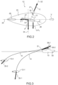
- the fish 12 is configured to move in the water in translation in a direction 25 shown horizontally on the figure 2 .
- the fish 12 comprises a frame 23 and at at least one wing 27 for generating for the fish 12 a hydrodynamic lift P directed downwards when the fish 12 moves in the direction 25.
- the fish 12 itself and other appendages of the fish 12 participate in the generation of the overall hydrodynamic lift of the fish 12.
- the wing 27 mainly generates the overall hydrodynamic lift of the fish 12.
- the wing 27 has for example a symmetrical profile around a direction 28.
- the direction 28 of the wing 27 is inclined at an angle ⁇ relative to the direction 25.
- the angle ⁇ is oriented negatively in the trigonometric sense in order to direct the lift P downwards.
- the fish 12 may also comprise a tail 29 located towards the rear of the fish 12 in the direction of movement of the fish along the direction 25. The tail 29 makes it possible to ensure the stability of the movement of the fish 12 in the direction 25.
- the cross 21 is movable in rotation relative to the frame 23 around a horizontal axis 30 perpendicular to the main direction 25.
- the axis 30 is perpendicular to the plane of the figure 2 .
- the horizontal axis 30 and the direction 25 are defined relative to the external shapes of the fish 12 orienting it in the water when it is towed by the cable 14.
- the fish 12 comprises for example a pivot connection 31 allowing the stock 21 and the frame 23 to be articulated between them.
- the pivot connection 31 allows the stock 21 to rotate relative to the frame 23 around the horizontal axis 30.
- the stock 21 has for example a sleeve in which the cable 14 is threaded.
- the sleeve extends along an axis 32.
- the cable 14 In the vicinity of the stock 21, the cable 14 also extends along the axis 32. More precisely, the cable 14 and the stock 21 are integral with each other.
- the connection between the cable 14 and the stock 21 is of the complete connection type also called a built-in connection.
- An angle ⁇ is defined between the axis 32 and the main direction 25 around the horizontal axis 30. In the vicinity of the fish 12, the cable 14 makes an angle ⁇ with the main horizontal direction 25.
- connection between the cross 21 and the frame 23 may comprise more than one degree of freedom in rotation. It may be a two-degree-of-freedom finger ball joint or a three-degree-of-freedom ball joint. For the implementation of the invention, only the angle ⁇ defined around the horizontal axis 30 is taken into account.
- the fish is subjected to different forces when it moves in direction 25: its weight G and the Archimedes' thrust F A , both represented by the same vector on the figure 2 , its drag T and the traction C exerted by the cable 14.
- the antenna 13 is absent. The possible presence of an antenna 13 would increase the drag T.
- the fish 12 comprises means for modifying the hydrodynamic lift of the wing 27 and therefore the overall hydrodynamic lift P of the fish 12.
- the lift P is here considered to be positive when it is directed downwards.
- the fish 12 has a lift subsequently called operational lift.
- This lift is ensured by an angle ⁇ of inclination of the wing 27 oriented downwards.
- the sign of the angle ⁇ is considered positive in the trigonometric sense.
- the angle ⁇ therefore has a negative value, for example of the order of -8°, to direct the lift P downwards and ensure the mission of the fish 12 in operational condition. It is understood that this angle value can be adapted according to the desired lift and the profile of the wing 27.
- the lift P of the fish 12 is reduced by modifying the angle ⁇ . Indeed, by reducing the lift P, the vector sum of the forces exerted on the fish 12 to balance the traction C is reduced and consequently the modulus of the traction C.
- the reduction of the lift P can be achieved by means of a single-piece wing whose inclination can be modified. It is also possible to add a movable flap at the end of a fixed wing.
- the reduction in lift can of course go as far as cancelling the lift and even making it negative, that is to say directed towards the high and tending to bring the fish 12 up towards the surface.
- too much negative lift would tend to increase the traction C on the cable 14.
- a rise of the fish 12 may be of interest when a shallow bottom appears.
- the lift P and the drag T are functions of the speed V of the fish 12 in the direction 25. This speed is at first approximation equal to the speed of the ship 10 when the fish 12 is in equilibrium. The more the speed V increases, the greater the lift P and the drag T. To maintain the balance of the forces exerted on the fish 12, the algebraic value of the traction C increases and the angle ⁇ also increases. For a given angle ⁇ , there is a function relating the angle ⁇ and the algebraic value of the traction T. In practice, the angle ⁇ varies as a function of the lift P and the drag T. The dimensions of the fish 12 are defined so that the angle ⁇ varies as a function of the speed V.
- the invention takes advantage of this relationship by controlling the orientation ⁇ of the wing 27 as a function of the angle ⁇ .
- the traction modulus C is reduced.
- the orientation of the wing 27 defined by the angle ⁇ is a function of an angle formed between the stock 21 and the frame 23 around the horizontal axis 30.
- this angle is considered to be the angle ⁇ between the cable 14 in the vicinity of the fish 12 and the main direction 25.
- the angle between the stock 21 and the frame 23 used to modify the orientation of the wing 27 can be offset by a fixed value depending on the configuration of the means for attaching the cable 14 to the stock 21.
- a variation in the angle ⁇ results in a variation in the orientation of the wing 27.
- FIG 3 represents two configurations in which the ship 10 tows the fish 12.
- the first configuration is the operational configuration and the fish 12 is marked 12-1.
- the wing 27 provides downward lift.
- the vector sum of the forces due to the weight G, the Archimedes' thrust F A , the drag T and the lift P is marked 35-1.
- This vector sum is opposite the traction C of the cable 14 on the fish 12.
- the resultant 35-1 causes a traction force 36-1 on the cable 14.
- the second configuration is called the escape configuration and the fish is marked 12-2. In the escape configuration, controlled by a variation of the angle ⁇ , the lift of the wing 27 has been reduced.
- the vector sum of the forces due to the weight G, the Archimedes' thrust F A , and the drag is marked 35-2. It is considered that in the leakage configuration, the lift P is zero. At the level of the ship 10, the resultant 35-2 causes a traction force 36-2 on the cable 14.
- the modulus of the tractive effort 36-2 is less than the modulus of the tractive effort 36-1. If the entire towing chain (winch, cable and fish) is sized to operate with a 36-1 effort at a given speed for the vessel 10, reducing the lift of the fish 12 allows the given speed to be increased until a 36-2 effort is reached whose modulus is equal to the modulus of the 36-1 effort at a lower speed.
- a single wing 27 is shown on one side of the fish 12. It is conventional for the fish 12 to comprise two wings 27 each arranged symmetrically with respect to the direction 25. In this case, the means for modifying the orientation ⁇ advantageously apply in a coordinated manner to the two wings 27. More generally, the fish 12 may comprise more than two wings all generating downward-directed lift. The invention already has an advantage in reducing the lift of one of the wings. Conversely, the fish 12 may comprise only one wing, for example arranged on the nose of the fish 12. The invention then consists of reducing the lift of this single wing.
- the wing 27 is movable in rotation relative to the frame 23 around a horizontal axis 33 parallel to the axis 30 of rotation of the butt 21.
- the tail 29 of the fish 12 is here fixed relative to the frame 23.
- This configuration makes it possible to maintain the overall attitude of the fish 12 when the angle ⁇ is modified.
- the directions of the weight G and the Archimedes' thrust F A are not modified relative to the frame 23.
- the fish is then in better conditions to support an increase in its speed.
- This configuration with a mobile tail makes it possible to limit the forces to be exerted on the mobile appendage, in this case the tail, to reduce the lift of the fish 12.
- the appendages intended to vary the attitude of an object navigating in a fluid, in the air or in water are articulated around an axis located in the vicinity of their leading edge in order to ensure their stability.
- FIGs 4 and 5 represent an example of a law for controlling the angle ⁇ of orientation of the wing 27 as a function of the angle ⁇ of the crosshead 21 relative to the frame 23.
- the angle ⁇ is represented on the abscissa and the angle ⁇ on the ordinate.
- the figure 4 represents the evolution of the angle ⁇ when the angle ⁇ decreases and the figure 5 when the angle ⁇ increases.
- the law is represented on a bundle of curves representing for each at a given speed V the angle ⁇ that the fish 21 naturally takes as a function of the angle ⁇ of orientation of the wing 27 in the absence of a piloting law.
- the law is defined so that between the two extreme speeds of 13 and 20 knots, a transition takes place between the operational lift value and the vanishing lift value.
- wing 27 is oriented downwards to obtain operational lift.
- the angle ⁇ is set to a first value, for example negative -10.5°, to obtain the operational lift.
- the tail angle is greater than 52° and the angle ⁇ remains constant at the value of -10.5°.
- the law is defined so as to reduce the angle ⁇ when the tail angle becomes less than 52°.
- the threshold for triggering the reduction in lift of the wing 27 is set at 52°. This threshold is marked 41 on the figure 4 . In other words, since there is a relationship between the crosshead angle ⁇ and the speed V, the angle ⁇ is reduced when the speed becomes greater than 16 knots.
- a second threshold 42 of angle ⁇ is defined below which the angle ⁇ of orientation of the wing 27 is set to a second value greater than the value defined when the hook angle ⁇ is greater than the first threshold 41.
- the second value of angle ⁇ can remain negative or positive or zero. In the example illustrated, the second value is 0°.
- a positive value may be of interest for generating upward lift and partially compensating for the weight G.
- the value of the angle ⁇ is 19°. At this value, the lift is reduced compared to the operational lift. This lift can be called trailing lift.
- the steering law is stable up to a stock angle of 40° corresponding to a speed of 19 knots.
- This stable part is marked 43 on the figure 4 .
- the piloting law enters an unstable part 44.
- the angle ⁇ of orientation of the wing 27 tends to increase jointly with a decrease in the angle ⁇ of the crosshead 21 until reaching the threshold 42 while keeping the speed of 19 knots substantially constant, except for its acceleration.
- threshold 42 corresponds to a crosse angle ⁇ of 19° and a wing orientation angle 27 ⁇ of 0°.
- the threshold between the stable and unstable parts is marked 45 on the figure 4 .
- the unstable part of the curve allows the lift of the wing 27 and the angle ⁇ of the butt to be reduced rapidly.
- the modulus of the traction C also decreases rapidly, which allows the ship 10 to accelerate further for a better escape.
- the slope of the curve defining the control law is lower than the slope of each of the curves of the beam defining the equilibrium of the fish 12 as a function of the angles ⁇ and ⁇ . More precisely, the curve defining the control law intersects several curves of the beam and at each intersection, the slope of the curve defining the control law is lower than the curve of the beam. On the contrary, in the unstable part of the control law, the slope of the curve defining the control law is higher than the curve of the intersected beam. Applied to the example of the figure 4 , when the speed increases and reaches 19 knots, fish 12 automatically rises until it reaches the equilibrium point defined by threshold 42. In practice, fish 12 can take several minutes to cross the unstable part and go from point 45 to point 42 due to its inertia.
- the angle ⁇ of the hook 21 will continue to decrease, but the angle ⁇ of orientation of the wing 27 remains fixed at a value of 0°.
- the ship can exceed 20 knots with a reduced traction force on the cable 14 compared to the force of traction that would be generated with an operational lift obtained with an angle ⁇ of orientation of the wing 27 of -10.5°.
- the angle ⁇ of orientation of wing 27 remains at 0°.
- the angle ⁇ of orientation of the wing 27 tends to decrease jointly with an increase in the angle ⁇ of the hook 21 until reaching the threshold 41 while keeping the speed of 16 knots substantially constant, except for its deceleration.
- the piloting law is completely unstable between the two angles ⁇ of orientation of the wing 27 from 0° to -10.5°.
- the curve defining the piloting law crosses iso-speed curves of the beam greater than 16 knots.
- the unstable part of the piloting law allows to obtain a hysteresis between acceleration and deceleration. More precisely, during acceleration, it is necessary to reach the speed of 19 knots to enter the unstable part and reach threshold 42. On the other hand, during deceleration as long as the speed remains above 16 knots, the orientation ⁇ of the wing 27 remains at its value of 0°.
- the control law includes a stable part and an unstable part. It is possible to define the entire law in a stable domain. There is then no hysteresis. Conversely, it is possible to define the control law in a completely unstable manner between the two thresholds 41 and 47, which makes it possible to reduce the traction on the cable more quickly. A control law defined in a completely unstable manner tends to increase the hysteresis. Too great a hysteresis would impose on the ship 10 to slow down too much to recover operational lift.
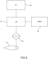
- the fish 12 comprises an angle sensor 50 for determining the angular position of the stock 21 relative to the frame 23.
- the sensor 50 is for example a resolver arranged in the pivot connection 31. Any other type of angle sensor can be used.
- the fish 12 also comprises a computer 51, a memory 52 and an actuator 53 for modifying the orientation of the wing 27 around its axis 33.
- the actuator 53 can be an electric stepper motor orienting the wing 27.
- a microcontroller can be implemented.
- the calculator 51 is configured to control the actuator 53 as a function of the angle ⁇ determined by the sensor 50.
- the memory 52 contains the control law of the actuator 53 as a function of the angle ⁇ and a program allowing the implementation of the control law.
- the main interest of the first embodiment lies in its flexibility of implementation. It is indeed possible to modify the control law easily by replacing the content of the memory 52. On the other hand, the presence of electronic components can degrade the reliability of this embodiment.
- the Figures 7a, 7b and 7c describe a second embodiment of the control of the orientation of the wing 27 as a function of the angle ⁇ .
- the second embodiment is completely mechanical without motorization. It is only the hydrodynamic forces (drag and lift), gravity, cable traction and Archimedes exerted on the fish 12 which make it possible to modify the orientation ⁇ of the wing 27 as a function of the angle ⁇ .
- the fish 12 comprises a cam and a cam follower.
- the cam is integral with the wing 27 and the cam follower is integral with the stock 21.
- the cam follower relies on a shape of the cam during rotation of the stock 21 around the horizontal axis 30.
- FIG. 7a represents in perspective, the cross 21, two wings 27 as well as the cam and the cam follower. To facilitate understanding, the frame 23 is not shown.
- the Figure 7b represents in perspective the cam integral with the wings 27 and the figure 7c represents the cam follower attached to the stock 21.
- the cam is formed by two symmetrical grooves 60 and the cam follower is formed by two pins 61, each guided in one of the grooves 60.
- the axis 33 of rotation of the wing 27 relative to the frame 23 can be arranged in a substantially secant manner with a vertical axis 34 carrying the lift force generated by the wing 27. This makes it possible to limit the torque necessary for the rotation of the wing. This torque can even be almost zero, negative or positive. In this configuration, it is useful to provide for the cam follower to bear bidirectionally on the cam.
- the grooves 60 allow this bidirectional support. In other words, in each of the grooves, the pin 61 considered can bear on one of the lateral faces of the corresponding groove 60.
- cam and cam follower are of course possible within the scope of the invention.
- FIGS. 8a to 8f represent different orientations ⁇ of the wing 27 as functions of the angle ⁇ of the butt 21 for the second embodiment. The description of these figures is made when the angle ⁇ increases from the Figure 8a towards the figure 8f . Conversely, when the angle ⁇ decreases, the relative configuration of the cross 21 and the wing 27 changes from figure 8f towards the Figure 8a .
- the crosse angle ⁇ is equal to 90° and the orientation ⁇ of the wing 27 is -10.5°.
- the angle of crosse ⁇ is equal to 73° and the orientation ⁇ of the wing 27 is also -10.5°. In these two configurations, the crosse angle ⁇ is greater than the threshold 41 and the orientation ⁇ of the wing 27 remains constant so as to generate the operational lift.
- the profile of the cam i.e. the shape of the grooves 60 on which the two pins 61 rest, is an arc of a circle of radius R1 centered on the axis 30 of rotation of the crosshead 21. It is possible to secure this part of the piloting law by adding a lock 65 formed by two mechanical parts 66 and 67, one, 66, fixed to the crosshead 21 and the other, 67, fixed to the wing 27.
- the crosshead angle ⁇ is generally equal to or close to 90° because the fish 12 is suspended out of the water by the cable 14. During these maneuvers, the wing 27 risks receiving impacts.
- the lock 65 makes it possible to absorb these possible shocks in order to prevent the grooves 60 and the pins 61 from being stressed.
- Lock 65 is visible in an insert of the figure 8b , in which the two mechanical parts 66 and 67 are shown in section.
- the part 66 comprises a cylindrical portion 68 centered on the axis 30 and extending in an angular sector ⁇ 1 .
- the part 67 comprises a cylindrical portion 69 centered on the axis 30 and extending in an angular sector ⁇ 2 .
- the two cylindrical portions 68 and 69 have the same radius, apart from the functional clearance, and are pressed against each other as long as the angle ⁇ remains greater than the threshold 41.
- the lock 65 prevents any rotation of the wing 27 and the angle ⁇ remains fixed at a value of -10.5°.
- the lock 65 is released.
- the shapes implemented for the lock 65 can also be used to fix the value of the angle ⁇ at the value of 0° when the angle ⁇ is less than the value of the threshold 42.
- the lock 65 is released and the butt angle ⁇ reaches the threshold 41 at a value of 52°.
- the orientation ⁇ of the wing 27 is still -10.5°.
- the crosse angle ⁇ reaches the threshold 45 at a value of 40°.
- the orientation ⁇ of the wing 27 is -6°.
- the cross angle ⁇ is 25°. This angle ⁇ corresponds to the balance point 47 shown on the figure 5 .
- the orientation ⁇ of wing 27 is 0° there.
- the butt angle ⁇ reaches the threshold 42 and has a value of 19° without changing the orientation ⁇ of the wing 27 to 0°.
- a second lock can immobilize the butt 21 relative to the frame 23 when the angle ⁇ reaches a minimum value, 15° in the example shown.
- the lock can be produced by means of the two mechanical parts 66 and 67 each comprising a stop, respectively 71 and 72 bearing on each other when the angle ⁇ reaches the desired value.
- the two stops 71 and 72 of the lock are visible on the Figures 7b and 7c .
- the shapes of the stops 71 and 72 can be implemented to immobilize the stock 21 relative to the frame 23 when the angle ⁇ reaches a maximum value, for example 90° as shown in the figure.
- Figure 8a the shapes of the stops 71 and 72 can be implemented to immobilize the stock 21 relative to the frame 23 when the angle ⁇ reaches a maximum value, for example 90° as shown in the figure.
Landscapes
- Engineering & Computer Science (AREA)
- Mechanical Engineering (AREA)
- Aviation & Aerospace Engineering (AREA)
- Life Sciences & Earth Sciences (AREA)
- Ocean & Marine Engineering (AREA)
- Combustion & Propulsion (AREA)
- Chemical & Material Sciences (AREA)
- Physics & Mathematics (AREA)
- Environmental & Geological Engineering (AREA)
- General Physics & Mathematics (AREA)
- Geophysics (AREA)
- General Life Sciences & Earth Sciences (AREA)
- Remote Sensing (AREA)
- Geology (AREA)
- Acoustics & Sound (AREA)
- Oceanography (AREA)
- Mechanical Means For Catching Fish (AREA)
- Measurement Of Velocity Or Position Using Acoustic Or Ultrasonic Waves (AREA)
- Structures Of Non-Positive Displacement Pumps (AREA)
- Farming Of Fish And Shellfish (AREA)
- Catching Or Destruction (AREA)
Claims (11)
- Schleppgerät, bestimmt zum Eintauchen und Schleppen mit einem Kabel (14), wobei das Schleppgerät (12) eine zum Bewegen im Wasser entlang einer horizontalen Hauptrichtung (25) konfigurierte Tragstruktur (23) und mindestens einen Anhang (27) umfasst, der zum Erzeugen eines nach unten gerichteten hydrodynamischen Auftriebs (P) für das Schleppgerät (12) konfiguriert ist, wenn das Schleppgerät (12) sich unter der Wirkung des Schleppens im Wasser bewegt, wobei der Anhang (27) orientiert werden kann, um seinen Auftrieb zu verändern, wobei das Schleppgerät (12) einen Kreuzkopf (21) umfasst, der in Bezug auf die Tragstruktur (23) um eine horizontale Achse (30) lotrecht zur horizontalen Hauptrichtung (25) drehbar ist, wobei das Kabel (14) zum Befestigen an dem Kreuzkopf (21) bestimmt ist, wobei das Schleppgerät (12) einen nicht motorisierten Mechanismus umfasst, der so konfiguriert ist, dass eine Orientierung (γ) des Anhangs (27), die es ihm ermöglicht, den Auftrieb (P) zu verändern, abhängig von einem Winkel (β) zwischen dem Kreuzkopf (21) und der Tragstruktur (23) ist, definiert auf der Basis der horizontalen Hauptrichtung (25), wobei ein Gesetz, das den Winkel (β) mit der Orientierung (γ) des Ansatzes (27) verbindet, so konfiguriert ist, dass, wenn der Wert des Winkels (β) abnimmt, die Orientierung (γ) des Anhangs (27) vergrößert wird, um den hydrodynamischen Auftrieb (P) des Schleppgeräts (12) zu verringern, und wobei oberhalb eines ersten gegebenen Wertes des Winkels (β) die Orientierung (γ) des Anhangs (27) fest ist, um einen sogenannten Betriebsauftrieb des Schleppgeräts (12) zu erzeugen, und unterhalb des ersten gegebenen Winkelwertes (β) die Orientierung (γ) des Anhangs (27) erhöht wird, wenn der Wert des Winkels (β) abnimmt, um den Auftrieb in Bezug auf den Betriebsauftrieb zu reduzieren.
- Schleppgerät nach Anspruch 1, dadurch gekennzeichnet, dass über einen Wertebereich des Winkels (β) das Gesetz instabil ist, so dass ein gegebener Wert der Orientierung (γ) des Anhangs (27) zu einer Verringerung des Winkels (β) führt.
- Schleppgerät nach einem der vorhergehenden Ansprüche, dadurch gekennzeichnet, dass unterhalb eines gegebenen zweiten Winkelwertes (β), der kleiner als der gegebene erste Winkelwert ist, die Orientierung (γ) des Anhangs (27) fest ist, so dass ein sogenannter Fluchtauftrieb erzeugt wird, der kleiner als der Betriebsauftrieb ist.
- Schleppgerät nach Anspruch 3, dadurch gekennzeichnet, dass unterhalb des zweiten gegebenen Winkelwertes (β) die Orientierung des Anhangs (27) positiv oder null ist.
- Schleppgerät nach Anspruch 3 oder 4, dadurch gekennzeichnet, dass ein dritter Winkelwert (β) zwischen dem ersten und dem zweiten Winkelwert vorgegeben ist, und dadurch, dass zwischen dem ersten und dem dritten Winkelwert ein Gesetz, das den Winkel (β) mit der Orientierung (γ) des Anhangs (27) verbindet, so konfiguriert ist, dass der Winkel (β) auf einem stabilen Wert gehalten wird.
- Schleppgerät nach den Ansprüchen 2 und 5, dadurch gekennzeichnet, dass der Wertebereich des Winkels (β), in dem das Gesetz instabil ist, zwischen dem dritten und dem zweiten Winkelwert definiert ist, und dadurch, dass das Gesetz so konfiguriert ist, dass der Anhang (27) zum Erreichen des Fluchtauftriebs orientiert wird.
- Schleppgerät nach einem der vorhergehenden Ansprüche, dadurch gekennzeichnet, dass es einen den Anhang bildenden tragenden Flügel (27) und ein stabilisierendes Leitwerk (29) umfasst, das so konfiguriert ist, dass es einen Trimm des Schleppgeräts (12) bei Änderungen der Orientierung (γ) des Anhangs (27) im Wesentlichen konstant hält.
- Schleppgerät nach einem der vorhergehenden Ansprüche, dadurch gekennzeichnet, dass der Anhang (27) in Bezug auf die Tragstruktur (23) um eine zweite horizontale Achse (33) drehbar ist, wobei die Beweglichkeit des Anhangs (27) es zulässt, den Auftrieb (P) des Schleppgeräts (12) zu verändern, und dadurch, dass sich die zweite horizontale Achse (33) zur Drehung des Anhangs (27) im Wesentlichen im momentanen Drehzentrum des Schleppgeräts (12) befindet, wenn dieser aufgrund einer Änderung der Orientierung (γ) des Anhangs (27) schwenkt.
- Schleppgerät nach einem der vorhergehenden Ansprüche, dadurch gekennzeichnet, dass er einen Nocken (60) und einen Nockenfolger (61) umfasst, von denen einer mit dem Anhang (27) und der andere mit dem Kreuzkopf (21) fest verbunden ist, und dadurch, dass der Nockenfolger (61) bei der Drehung des Kreuzkopfs (21) um die horizontale Achse (30) auf einer Form des Nockens (60) aufliegt.
- Schleppgerät nach Anspruch 8, dadurch gekennzeichnet, dass es einen ersten Riegel (65) umfasst, der zum Halten des Anhangs (27) in einer festen Orientierung (γ) konfiguriert ist, wenn der Wert des Winkels (β) über dem ersten gegebenen Winkelwert liegt.
- Schleppgerät nach Anspruch 9 oder 10 als von Anspruch 3 abhängige Ansprüche, dadurch gekennzeichnet, dass es einen zweiten Riegel (71, 72) umfasst, der zum Fixieren des Kreuzkopfs (21) in Bezug auf die Tragstruktur (23) konfiguriert ist, wenn der Wert des zwischen dem Kreuzkopf (21) und der Tragstruktur (23) gebildeten Winkels (β) unterhalb des zweiten gegebenen Winkelwerts liegt.
Applications Claiming Priority (2)
| Application Number | Priority Date | Filing Date | Title |
|---|---|---|---|
| FR1701323A FR3075164B1 (fr) | 2017-12-19 | 2017-12-19 | Poisson a portance hydrodynamique variable de facon reversible et ligne de remorquage comprenant le poisson |
| PCT/EP2018/085585 WO2019121743A1 (fr) | 2017-12-19 | 2018-12-18 | Poisson à portance hydrodynamique variable de façon réversible et ligne de remorquage comprenant le poisson |
Publications (3)
| Publication Number | Publication Date |
|---|---|
| EP3729144A1 EP3729144A1 (de) | 2020-10-28 |
| EP3729144B1 true EP3729144B1 (de) | 2024-09-04 |
| EP3729144C0 EP3729144C0 (de) | 2024-09-04 |
Family
ID=62222709
Family Applications (1)
| Application Number | Title | Priority Date | Filing Date |
|---|---|---|---|
| EP18816142.6A Active EP3729144B1 (de) | 2017-12-19 | 2018-12-18 | Schleppsensor mit variablem hydrodynamischem auftrieb und schlepptau mit dem schleppsensor |
Country Status (6)
| Country | Link |
|---|---|
| US (1) | US11396348B2 (de) |
| EP (1) | EP3729144B1 (de) |
| AU (1) | AU2018391787B2 (de) |
| CA (1) | CA3086075A1 (de) |
| FR (1) | FR3075164B1 (de) |
| WO (1) | WO2019121743A1 (de) |
Families Citing this family (3)
| Publication number | Priority date | Publication date | Assignee | Title |
|---|---|---|---|---|
| NO347397B1 (en) * | 2019-09-12 | 2023-10-16 | Kongsberg Maritime As | Intermediate docking station for underwater vehicles |
| DE102020206996A1 (de) | 2020-06-04 | 2021-12-09 | Thyssenkrupp Ag | Tiefenvariables Schleppsonar sowie Verfahren zum Betreiben |
| CN114852288B (zh) * | 2022-03-24 | 2023-04-18 | 中国船舶科学研究中心 | 一种有缆载人潜水器作业系统及操作方法 |
Family Cites Families (6)
| Publication number | Priority date | Publication date | Assignee | Title |
|---|---|---|---|---|
| US3613626A (en) * | 1970-03-20 | 1971-10-19 | Raymond E Kelly | Remote operated lift control device |
| FR2655940A1 (fr) * | 1980-05-09 | 1991-06-21 | Eca | Dispositif sous-marin remorque a aile portante. |
| US5000110A (en) * | 1989-09-27 | 1991-03-19 | Moore Barry B | Towline depressor |
| GB2309952A (en) * | 1996-02-06 | 1997-08-13 | Clevis Fulcrum Ltd | Controlling the azimuth and elevation of a towed object |
| GB2414976B (en) * | 2004-06-07 | 2008-03-05 | Thales Uk Plc | Towing device adapted to stabilise a towed body |
| FR3033157B1 (fr) | 2015-02-27 | 2018-03-23 | Thales | Poisson a portance hydrodynamique variable et ligne de remorquage comprenant le poisson |
-
2017
- 2017-12-19 FR FR1701323A patent/FR3075164B1/fr active Active
-
2018
- 2018-12-18 CA CA3086075A patent/CA3086075A1/fr active Pending
- 2018-12-18 EP EP18816142.6A patent/EP3729144B1/de active Active
- 2018-12-18 WO PCT/EP2018/085585 patent/WO2019121743A1/fr not_active Ceased
- 2018-12-18 US US16/955,032 patent/US11396348B2/en active Active
- 2018-12-18 AU AU2018391787A patent/AU2018391787B2/en active Active
Also Published As
| Publication number | Publication date |
|---|---|
| FR3075164B1 (fr) | 2020-08-28 |
| EP3729144A1 (de) | 2020-10-28 |
| US20200377179A1 (en) | 2020-12-03 |
| WO2019121743A1 (fr) | 2019-06-27 |
| US11396348B2 (en) | 2022-07-26 |
| AU2018391787A1 (en) | 2020-06-25 |
| EP3729144C0 (de) | 2024-09-04 |
| FR3075164A1 (fr) | 2019-06-21 |
| AU2018391787B2 (en) | 2024-06-27 |
| CA3086075A1 (fr) | 2019-06-27 |
Similar Documents
| Publication | Publication Date | Title |
|---|---|---|
| EP3261920B1 (de) | Schleppsensor mit variablem hydrodynamischem auftrieb und schlepptau mit dem schleppsensor | |
| FR2925231A1 (fr) | Antenne sonar d'emission a axe vertical enroulable sur un treuil | |
| EP2776309B1 (de) | Schleppvorrichtung mit einer schwenkbarem klüse | |
| WO2019121743A1 (fr) | Poisson à portance hydrodynamique variable de façon réversible et ligne de remorquage comprenant le poisson | |
| CA2784188A1 (fr) | Engin marin ou sous-marin et procede d'arrimage associe | |
| EP0584190B1 (de) | Winde zum schleppen von unterwasserobjekten | |
| EP3209546B1 (de) | System zum aussetzen und bergen von see- und unterseevorrichtungen mit unterstützung durch kippbare schutzkomponenten | |
| EP3976461B1 (de) | Unterwasservorrichtung und unterwassersystem | |
| FR2740427A1 (fr) | Navire tracte par cerf-volant via un bras articule | |
| EP3523190B1 (de) | Selbstöffnende seilführung und schleppvorrichtung mit der seilführung | |
| EP0290325B1 (de) | System zur Erforschung und Überwachung des Meeresbodens mit einem Unterwasserfahrzeug und zu dessen Steuerung | |
| EP2621796B1 (de) | System mit einem unterwasserfahrzeug und einer basis an der oberfläche | |
| CA2222314C (fr) | Emetteur acoustique remorque | |
| EP4041625B1 (de) | Geschleppte unterwasservorrichtung und system zur handhabung der unterwasservorrichtung | |
| EP3976460B1 (de) | Sonarvorrichtung und sonarsystem | |
| EP3245123B1 (de) | Vorrichtung zum schutz von geschleppten unterwassergegenständen vor angelleinen | |
| EP3871000B1 (de) | Sonarsystem | |
| WO1991007310A1 (fr) | Treuil pour remorquage d'objets immerges | |
| EP4526201A1 (de) | Gezogenes unterwassergerät | |
| CA3088656A1 (fr) | Bateau comportant un cerf-volant |
Legal Events
| Date | Code | Title | Description |
|---|---|---|---|
| STAA | Information on the status of an ep patent application or granted ep patent |
Free format text: STATUS: UNKNOWN |
|
| STAA | Information on the status of an ep patent application or granted ep patent |
Free format text: STATUS: THE INTERNATIONAL PUBLICATION HAS BEEN MADE |
|
| PUAI | Public reference made under article 153(3) epc to a published international application that has entered the european phase |
Free format text: ORIGINAL CODE: 0009012 |
|
| STAA | Information on the status of an ep patent application or granted ep patent |
Free format text: STATUS: REQUEST FOR EXAMINATION WAS MADE |
|
| 17P | Request for examination filed |
Effective date: 20200624 |
|
| AK | Designated contracting states |
Kind code of ref document: A1 Designated state(s): AL AT BE BG CH CY CZ DE DK EE ES FI FR GB GR HR HU IE IS IT LI LT LU LV MC MK MT NL NO PL PT RO RS SE SI SK SM TR |
|
| AX | Request for extension of the european patent |
Extension state: BA ME |
|
| DAV | Request for validation of the european patent (deleted) | ||
| DAX | Request for extension of the european patent (deleted) | ||
| STAA | Information on the status of an ep patent application or granted ep patent |
Free format text: STATUS: EXAMINATION IS IN PROGRESS |
|
| 17Q | First examination report despatched |
Effective date: 20221205 |
|
| GRAP | Despatch of communication of intention to grant a patent |
Free format text: ORIGINAL CODE: EPIDOSNIGR1 |
|
| STAA | Information on the status of an ep patent application or granted ep patent |
Free format text: STATUS: GRANT OF PATENT IS INTENDED |
|
| INTG | Intention to grant announced |
Effective date: 20240411 |
|
| GRAS | Grant fee paid |
Free format text: ORIGINAL CODE: EPIDOSNIGR3 |
|
| GRAA | (expected) grant |
Free format text: ORIGINAL CODE: 0009210 |
|
| STAA | Information on the status of an ep patent application or granted ep patent |
Free format text: STATUS: THE PATENT HAS BEEN GRANTED |
|
| AK | Designated contracting states |
Kind code of ref document: B1 Designated state(s): AL AT BE BG CH CY CZ DE DK EE ES FI FR GB GR HR HU IE IS IT LI LT LU LV MC MK MT NL NO PL PT RO RS SE SI SK SM TR |
|
| RAP3 | Party data changed (applicant data changed or rights of an application transferred) |
Owner name: THALES |
|
| REG | Reference to a national code |
Ref country code: GB Ref legal event code: FG4D Free format text: NOT ENGLISH |
|
| REG | Reference to a national code |
Ref country code: CH Ref legal event code: EP |
|
| REG | Reference to a national code |
Ref country code: IE Ref legal event code: FG4D Free format text: LANGUAGE OF EP DOCUMENT: FRENCH |
|
| REG | Reference to a national code |
Ref country code: DE Ref legal event code: R096 Ref document number: 602018074036 Country of ref document: DE |
|
| U01 | Request for unitary effect filed |
Effective date: 20240920 |
|
| U07 | Unitary effect registered |
Designated state(s): AT BE BG DE DK EE FI FR IT LT LU LV MT NL PT RO SE SI Effective date: 20241014 |
|
| U20 | Renewal fee for the european patent with unitary effect paid |
Year of fee payment: 7 Effective date: 20241121 |
|
| PG25 | Lapsed in a contracting state [announced via postgrant information from national office to epo] |
Ref country code: NO Free format text: LAPSE BECAUSE OF FAILURE TO SUBMIT A TRANSLATION OF THE DESCRIPTION OR TO PAY THE FEE WITHIN THE PRESCRIBED TIME-LIMIT Effective date: 20241204 |
|
| PG25 | Lapsed in a contracting state [announced via postgrant information from national office to epo] |
Ref country code: PL Free format text: LAPSE BECAUSE OF FAILURE TO SUBMIT A TRANSLATION OF THE DESCRIPTION OR TO PAY THE FEE WITHIN THE PRESCRIBED TIME-LIMIT Effective date: 20240904 Ref country code: GR Free format text: LAPSE BECAUSE OF FAILURE TO SUBMIT A TRANSLATION OF THE DESCRIPTION OR TO PAY THE FEE WITHIN THE PRESCRIBED TIME-LIMIT Effective date: 20241205 |
|
| PG25 | Lapsed in a contracting state [announced via postgrant information from national office to epo] |
Ref country code: HR Free format text: LAPSE BECAUSE OF FAILURE TO SUBMIT A TRANSLATION OF THE DESCRIPTION OR TO PAY THE FEE WITHIN THE PRESCRIBED TIME-LIMIT Effective date: 20240904 |
|
| PG25 | Lapsed in a contracting state [announced via postgrant information from national office to epo] |
Ref country code: RS Free format text: LAPSE BECAUSE OF FAILURE TO SUBMIT A TRANSLATION OF THE DESCRIPTION OR TO PAY THE FEE WITHIN THE PRESCRIBED TIME-LIMIT Effective date: 20241204 Ref country code: ES Free format text: LAPSE BECAUSE OF FAILURE TO SUBMIT A TRANSLATION OF THE DESCRIPTION OR TO PAY THE FEE WITHIN THE PRESCRIBED TIME-LIMIT Effective date: 20240904 |
|
| PG25 | Lapsed in a contracting state [announced via postgrant information from national office to epo] |
Ref country code: RS Free format text: LAPSE BECAUSE OF FAILURE TO SUBMIT A TRANSLATION OF THE DESCRIPTION OR TO PAY THE FEE WITHIN THE PRESCRIBED TIME-LIMIT Effective date: 20241204 Ref country code: PL Free format text: LAPSE BECAUSE OF FAILURE TO SUBMIT A TRANSLATION OF THE DESCRIPTION OR TO PAY THE FEE WITHIN THE PRESCRIBED TIME-LIMIT Effective date: 20240904 Ref country code: NO Free format text: LAPSE BECAUSE OF FAILURE TO SUBMIT A TRANSLATION OF THE DESCRIPTION OR TO PAY THE FEE WITHIN THE PRESCRIBED TIME-LIMIT Effective date: 20241204 Ref country code: HR Free format text: LAPSE BECAUSE OF FAILURE TO SUBMIT A TRANSLATION OF THE DESCRIPTION OR TO PAY THE FEE WITHIN THE PRESCRIBED TIME-LIMIT Effective date: 20240904 Ref country code: GR Free format text: LAPSE BECAUSE OF FAILURE TO SUBMIT A TRANSLATION OF THE DESCRIPTION OR TO PAY THE FEE WITHIN THE PRESCRIBED TIME-LIMIT Effective date: 20241205 Ref country code: ES Free format text: LAPSE BECAUSE OF FAILURE TO SUBMIT A TRANSLATION OF THE DESCRIPTION OR TO PAY THE FEE WITHIN THE PRESCRIBED TIME-LIMIT Effective date: 20240904 |
|
| PG25 | Lapsed in a contracting state [announced via postgrant information from national office to epo] |
Ref country code: IS Free format text: LAPSE BECAUSE OF FAILURE TO SUBMIT A TRANSLATION OF THE DESCRIPTION OR TO PAY THE FEE WITHIN THE PRESCRIBED TIME-LIMIT Effective date: 20250104 |
|
| PG25 | Lapsed in a contracting state [announced via postgrant information from national office to epo] |
Ref country code: SM Free format text: LAPSE BECAUSE OF FAILURE TO SUBMIT A TRANSLATION OF THE DESCRIPTION OR TO PAY THE FEE WITHIN THE PRESCRIBED TIME-LIMIT Effective date: 20240904 |
|
| PG25 | Lapsed in a contracting state [announced via postgrant information from national office to epo] |
Ref country code: CZ Free format text: LAPSE BECAUSE OF FAILURE TO SUBMIT A TRANSLATION OF THE DESCRIPTION OR TO PAY THE FEE WITHIN THE PRESCRIBED TIME-LIMIT Effective date: 20240904 |
|
| PG25 | Lapsed in a contracting state [announced via postgrant information from national office to epo] |
Ref country code: SK Free format text: LAPSE BECAUSE OF FAILURE TO SUBMIT A TRANSLATION OF THE DESCRIPTION OR TO PAY THE FEE WITHIN THE PRESCRIBED TIME-LIMIT Effective date: 20240904 |
|
| PG25 | Lapsed in a contracting state [announced via postgrant information from national office to epo] |
Ref country code: MC Free format text: LAPSE BECAUSE OF FAILURE TO SUBMIT A TRANSLATION OF THE DESCRIPTION OR TO PAY THE FEE WITHIN THE PRESCRIBED TIME-LIMIT Effective date: 20240904 |
|
| PLBE | No opposition filed within time limit |
Free format text: ORIGINAL CODE: 0009261 |
|
| STAA | Information on the status of an ep patent application or granted ep patent |
Free format text: STATUS: NO OPPOSITION FILED WITHIN TIME LIMIT |
|
| REG | Reference to a national code |
Ref country code: CH Ref legal event code: PL |
|
| 26N | No opposition filed |
Effective date: 20250605 |
|
| PG25 | Lapsed in a contracting state [announced via postgrant information from national office to epo] |
Ref country code: CH Free format text: LAPSE BECAUSE OF NON-PAYMENT OF DUE FEES Effective date: 20241231 |
|
| PG25 | Lapsed in a contracting state [announced via postgrant information from national office to epo] |
Ref country code: IE Free format text: LAPSE BECAUSE OF NON-PAYMENT OF DUE FEES Effective date: 20241218 |
|
| U20 | Renewal fee for the european patent with unitary effect paid |
Year of fee payment: 8 Effective date: 20251118 |
|
| PGFP | Annual fee paid to national office [announced via postgrant information from national office to epo] |
Ref country code: GB Payment date: 20251113 Year of fee payment: 8 |
|
| PGFP | Annual fee paid to national office [announced via postgrant information from national office to epo] |
Ref country code: TR Payment date: 20251211 Year of fee payment: 8 |