EP3524110A1 - Appareil d'aspiration doté d'un dispositif de recharge - Google Patents
Appareil d'aspiration doté d'un dispositif de recharge Download PDFInfo
- Publication number
- EP3524110A1 EP3524110A1 EP19164014.3A EP19164014A EP3524110A1 EP 3524110 A1 EP3524110 A1 EP 3524110A1 EP 19164014 A EP19164014 A EP 19164014A EP 3524110 A1 EP3524110 A1 EP 3524110A1
- Authority
- EP
- European Patent Office
- Prior art keywords
- charging
- suction
- suction device
- module
- energy storage
- Prior art date
- Legal status (The legal status is an assumption and is not a legal conclusion. Google has not performed a legal analysis and makes no representation as to the accuracy of the status listed.)
- Granted
Links
Images

Classifications
-
- A—HUMAN NECESSITIES
- A47—FURNITURE; DOMESTIC ARTICLES OR APPLIANCES; COFFEE MILLS; SPICE MILLS; SUCTION CLEANERS IN GENERAL
- A47L—DOMESTIC WASHING OR CLEANING; SUCTION CLEANERS IN GENERAL
- A47L9/00—Details or accessories of suction cleaners, e.g. mechanical means for controlling the suction or for effecting pulsating action; Storing devices specially adapted to suction cleaners or parts thereof; Carrying-vehicles specially adapted for suction cleaners
-
- A—HUMAN NECESSITIES
- A47—FURNITURE; DOMESTIC ARTICLES OR APPLIANCES; COFFEE MILLS; SPICE MILLS; SUCTION CLEANERS IN GENERAL
- A47L—DOMESTIC WASHING OR CLEANING; SUCTION CLEANERS IN GENERAL
- A47L5/00—Structural features of suction cleaners
- A47L5/12—Structural features of suction cleaners with power-driven air-pumps or air-compressors, e.g. driven by motor vehicle engine vacuum
- A47L5/22—Structural features of suction cleaners with power-driven air-pumps or air-compressors, e.g. driven by motor vehicle engine vacuum with rotary fans
- A47L5/36—Suction cleaners with hose between nozzle and casing; Suction cleaners for fixing on staircases; Suction cleaners for carrying on the back
- A47L5/365—Suction cleaners with hose between nozzle and casing; Suction cleaners for fixing on staircases; Suction cleaners for carrying on the back of the vertical type, e.g. tank or bucket type
-
- A—HUMAN NECESSITIES
- A47—FURNITURE; DOMESTIC ARTICLES OR APPLIANCES; COFFEE MILLS; SPICE MILLS; SUCTION CLEANERS IN GENERAL
- A47L—DOMESTIC WASHING OR CLEANING; SUCTION CLEANERS IN GENERAL
- A47L7/00—Suction cleaners adapted for additional purposes; Tables with suction openings for cleaning purposes; Containers for cleaning articles by suction; Suction cleaners adapted to cleaning of brushes; Suction cleaners adapted to taking-up liquids
- A47L7/009—Details of suction cleaner tools for additional purposes
-
- A—HUMAN NECESSITIES
- A47—FURNITURE; DOMESTIC ARTICLES OR APPLIANCES; COFFEE MILLS; SPICE MILLS; SUCTION CLEANERS IN GENERAL
- A47L—DOMESTIC WASHING OR CLEANING; SUCTION CLEANERS IN GENERAL
- A47L9/00—Details or accessories of suction cleaners, e.g. mechanical means for controlling the suction or for effecting pulsating action; Storing devices specially adapted to suction cleaners or parts thereof; Carrying-vehicles specially adapted for suction cleaners
- A47L9/28—Installation of the electric equipment, e.g. adaptation or attachment to the suction cleaner; Controlling suction cleaners by electric means
- A47L9/2857—User input or output elements for control, e.g. buttons, switches or displays
-
- A—HUMAN NECESSITIES
- A47—FURNITURE; DOMESTIC ARTICLES OR APPLIANCES; COFFEE MILLS; SPICE MILLS; SUCTION CLEANERS IN GENERAL
- A47L—DOMESTIC WASHING OR CLEANING; SUCTION CLEANERS IN GENERAL
- A47L9/00—Details or accessories of suction cleaners, e.g. mechanical means for controlling the suction or for effecting pulsating action; Storing devices specially adapted to suction cleaners or parts thereof; Carrying-vehicles specially adapted for suction cleaners
- A47L9/28—Installation of the electric equipment, e.g. adaptation or attachment to the suction cleaner; Controlling suction cleaners by electric means
- A47L9/2868—Arrangements for power supply of vacuum cleaners or the accessories thereof
- A47L9/2884—Details of arrangements of batteries or their installation
-
- H—ELECTRICITY
- H02—GENERATION; CONVERSION OR DISTRIBUTION OF ELECTRIC POWER
- H02J—ELECTRIC POWER NETWORKS; CIRCUIT ARRANGEMENTS OR SYSTEMS FOR SUPPLYING OR DISTRIBUTING ELECTRIC POWER; SYSTEMS FOR STORING ELECTRIC ENERGY
- H02J7/00—Circuit arrangements for charging or discharging batteries or for supplying loads from batteries
- H02J7/70—Circuit arrangements for charging or discharging batteries or for supplying loads from batteries characterised by the mechanical construction
- H02J7/751—Circuit arrangements for charging or discharging batteries or for supplying loads from batteries characterised by the mechanical construction concerning the insertion or the connection of the batteries
-
- H—ELECTRICITY
- H02—GENERATION; CONVERSION OR DISTRIBUTION OF ELECTRIC POWER
- H02J—ELECTRIC POWER NETWORKS; CIRCUIT ARRANGEMENTS OR SYSTEMS FOR SUPPLYING OR DISTRIBUTING ELECTRIC POWER; SYSTEMS FOR STORING ELECTRIC ENERGY
- H02J7/00—Circuit arrangements for charging or discharging batteries or for supplying loads from batteries
- H02J7/865—Battery or charger load switching, e.g. concurrent charging and load supply
Definitions
- the invention relates to a suction device for separating particles from a suction flow, with a suction motor for generating the suction flow and with a suction housing, in which the suction motor and a dust collecting space for collecting the separated from the suction flow particles is arranged.
- Such a suction device is for example off DE 10 2009 015 642 A1 known.
- the suction device sucks in particles via a suction hose, wherein the suction hose in turn can be connected to an electric hand-held machine tool in order to extract dust or particles generated by this hand-held machine tool during workpiece machining, for example sawing or drilling.
- the hand-held machine tool like the suction device, can be supplied with electrical energy by a rechargeable battery or an electrical energy store, so that the system can also be operated remotely from an electrical power supply, for example a 230V network.
- the energy storage of the suction device and the hand machine tool must be charged, ie at least one component of the entire assembly must be connected to a power grid.
- this is very uncomfortable.
- a suction device of the type mentioned has a charging device for charging an electrical energy storage module of a hand-held machine tool, wherein the charging device comprises electrical charging contacts for providing a charging voltage for the electrical energy storage module.
- the charging device is quasi on board the suction device, so that, for example, the already discharged energy storage module can be charged to the suction device, while the hand-held power tool is operated with another energy storage module.
- a separate charger for the hand-held power tool or its energy storage module is not necessary. The danger that a charger will be forgotten, for example, does not exist. If the suction device according to the invention is used, at the same time a charging device is available, for example on a construction site.
- the term "energy storage module” is to be understood that the electrical energy storage can also form an integral part of the hand-held machine tool. To recharge your energy storage then just the entire hand machine tool must be connected to the suction device or the charging device. However, a releasable configuration is preferred in which the energy storage module can be removed from a housing of the handheld machine tool such that a discharged energy storage module is against a freshly charged one Energy storage module can be replaced in a conventional manner.
- the suction device according to the invention is expediently a mobile suction device.
- the suction device preferably has wheels for driving on a ground.
- the suction device could also be a portable suction device which has rollers or has no rollers.
- the suction device according to the invention is expediently not designed as a self-sufficient, working in the manner of a robot suction device.
- the suction device can be taken by the operator and used on site.
- a suction hose can be connected to the suction device expediently.
- the charging contacts can be connected, for example, with a flexible cable or other electrical conductor with the power supplying them to the suction device.
- the cable or the conductor expediently form part of the suction device or is connected to it.
- a particularly preferred embodiment provides, however, that the charging device comprises a holder for holding the electrical energy storage module during the charging process.
- the holder advantageously has form-fitting contours which correspond to those which also have the hand-held machine tool in order to hold the electrical energy storage module.
- the holder comprises, for example, a plug-in receptacle or a plurality of plug receptacles and / or plug-in projections or more Plug-in projections to connect to the energy storage module.
- Locking means for latching the energy storage module e.g. at least one latching receptacle and / or at least one latching projection.
- the holder is expediently arranged on a control wall of the sucker housing provided for operating the suction device.
- the holder is available, for example, where else the operation of the nipple is done.
- the holder can also be arranged at a different location, for example an upper cover wall, a side wall or the like, of the sucker housing.
- the holder for holding the electric energy storage module during the charging process is on a recess or receiving recess provided for receiving a mains cable or is arranged on this recess or receiving recess.
- the charging device may form an integral part of the suction device in one embodiment of the invention, wherein the electrical charging contacts are arranged on the sucker housing. There is then also conveniently the holder.
- the charging device can also be of modular construction, ie that it can be designed, for example, as a separate from the sucker housing, a charger housing exhibiting loading module. On the sucker housing, in turn, a module receptacle for the loading module is arranged.
- the module holder can be one that, for example, also in DE 10 2009 015 642 A1 is described.
- a suction device communication module which can receive conduction-free control signals and does not form a device for charging an energy storage module for a hand-held machine tool, a radio module or the like can also be plugged into the module receptacle.
- An embodiment of the invention may expediently provide that the charging device is designed as a charging module and at the same time also forms a suction device communication module which is suitable for switching or activating the suction motor (a power control of the suction motor is also possible).
- the charging device may include an electrical switching device for switching on and off and / or for adjusting an electrical power of the suction motor or be designed to control such a switching device of the suction device.
- This switching device can, for example, measure a current flow which serves to supply power to an external device, for example a hand-held machine tool.
- the switching device comprises, for example, an electrical switch with which the suction motor is switched on or off or with which an electric power of the suction motor is adjustable.
- the charging device for example, the switching device, that is, that the charging device comprises a suction device communication device, such as a suction device receiver for receiving transmitted by an external communication device, wireless control signals and / or wireless message signals.
- the charging device then forms, for example, a Switching device, which is designed for controlling the suction motor, in particular for switching on and off, based on the wireless control signals.
- the message signals received without wires can indicate the charging device, for example, by means of display means (optical and / or acoustic display means) which expediently form part of the charging device.
- a particularly preferred embodiment provides that the charging device controls the electrical charging of the charge in the energy storage module based on the message signals, especially if the or the signaling signals indicate, for example, a state of charge of the externally operated, currently in use energy storage module.
- the external communication device can in this case form part of a system which comprises the charging device according to the invention. If, for example, the energy storage module currently in use is discharged relatively quickly, this transfers the external communication devices to the charging device on the basis of the signaling signal, which in turn then controls, for example, the charging process of the energy storage module to be charged as a function of the reporting signal, for example accelerating the electrical charging or slows down, the latter being gentle on the energy storage module to be charged, for example.
- the charging device can be configured as a suction device communication module and charging module, which can be removed from the suction device or its sucker housing. But it is also possible that the charging device forms an integral part of the suction device in this embodiment.
- the control signals and / or signaling signals transmitted or transferable without transmission are, for example, radio signals or optical signals or both.
- the communication means of the suction device communication device and the external communication device may comprise, for example, optical communication means or radio communication means.
- the communication interface of the suction device communication device and / or the external communication device may comprise, for example, a WLAN.
- infrared signals are possible.
- a line-of-sight connection is not necessary if the non-conducting signaling signals and / or control signals are or include radio signals. It is preferred if the radio signals can only be received by the suction device in a near range of, for example, up to a maximum of 2-8 m, so that interference by other external communication devices is not to be feared. As a rule, such a short range is also sufficient, since the suction device is also required at the location of the external communication device where dust particles are generated.
- an advantageous embodiment of the invention provides that the charging module or the suitable for charging the energy storage module suction device can communicate wirelessly with the energy storage module, for example, to control commands and / or To transfer messages from the suction device to the energy storage module and thus to the hand-held machine tool or vice versa from the hand-held machine tool to the suction device.
- the energy storage module receives a control command from the suction device to turn on or off the hand-held machine tool. It is also possible to send identification data of the suction device to the hand-held machine tool or to send the like or identification data of the hand-held machine tool to the suction device.
- the hand-held power tool which is equipped with such, an external communication device having energy storage module
- the suction device for example, wirelessly turns on or off.
- a conventional hand tool for example, with such an energy storage module for wireless communication with the suction device, so to speak.
- Even a conventional vacuum device is to be retrofitted with the charging module, which can then communicate wirelessly with the energy storage module and thus the hand-held machine tool.
- the energy storage module can, for example, detect a current flow when the hand-held machine tool is switched on and off and thus detect an operation of the hand-held machine tools and transmit it wirelessly to the loading module or the suction device in such a way that the hand-held machine tool is running or switched off.
- the charging module switches the suction device on or off, for example, changes its performance or the like.
- the charging device may in a preferred embodiment of the invention, a charging current for charging the energy storage module in response to the wireless control signals turn. It is thus possible, for example, for the charging device to switch on the charging current during a switch-on signal for the naturally aspirated engine and to switch it off for a switch-off signal for the naturally aspirated engine. If, for example, the suction device has a current sensor which measures a current flow to the charging device, the suction device recognizes from the signals of the current sensor whether there is a current flow or not. The flow of current virtually simulates a hand-held machine tool that is connected, for example, to an otherwise existing socket of the suction device.
- the charging device forms a charging module that can be plugged into a module receptacle of the suction device
- proprietary module contacts are preferably provided in the charging module and the module receptacle, that is not about protective contacts of the usual kind, which are common in power plugs, but contacts that only are present in the suction device according to the invention and the charging module according to the invention, so that a misuse is impossible.
- the charging voltage (L) is preferably a DC voltage and / or is suitably in a range of 5-25V
- the charging device expediently has current adaptation means and / or voltage adaptation means for providing the charging voltage on the basis of an input voltage which is provided, for example, by another electrical component of the suction device, for example via a mains cable from a 230 V network, or also power-electronic components which already have one provide a lower input voltage for the charging device and / or a DC voltage.
- the current adaptation means and / or voltage adaptation means ensure that the charging voltage is a DC voltage.
- the charging voltage is preferably in Range of 5-25 volts, corresponding to a typical charging voltage for an electrical energy store for hand-held machine tools. It is also possible that the charging voltage is for example 12 V, 15 V or 18 V.
- the charging device monitors the charging current and / or the state of charge of the energy storage module on the basis of monitoring means, so that the energy storage module is charged in a sufficient manner, but not too much.
- the suction device preferably has an internal electrical energy store. This may be, for example, an accumulator, i. a rechargeable, energy storage act.
- the suction device has, for example, a fuel cell, solar modules or the like other electric power generating means for providing electrical energy for the charging device.
- the charging device is expediently generously designed with electrical energy for charging the energy storage module or the hand-held power tool via the internal electrical energy store.
- a large capacity having internal electrical energy storage can be used to charge the relatively small energy storage of the energy storage module.
- the suction device is usually placed on a base, so that its weight does not play a significant role
- the energy storage module is preferably lightweight and compact, but can, so to speak, use the internal capacities of the suction device.
- the suction device preferably has a control device for controlling an electrical charge of the internal electrical energy store and the energy storage module.
- the control device preferably charges the internal electrical energy store, whereby electrical power upper limits are observed. Thus, it is prevented, for example, that an excessive mains current must be provided for the power supply of the suction device.
- the aforementioned control device or another control device is expediently designed to control an electrical charging of the energy storage module as a function of an operation of the intake engine. If, for example, an increased power requirement or even a power requirement is necessary for the naturally aspirated engine, the control device can reduce the charging current for charging the energy storage module. However, if the naturally aspirated engine is not running or is consuming less power, it will continue to charge at its optimum power, quickly charging the energy storage module.
- the suction device according to the invention is expediently not designed as a self-sufficient, working in the manner of a robot suction device.
- the suction device can be taken by the operator and used on site. Rollers for rolling on a substrate are expediently provided on the sucker housing. Furthermore, a suction hose can be connected to the suction device expediently.
- the suction device advantageously has a suction hose. On the sucker housing rollers are arranged for manual operation on a substrate expediently.
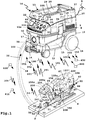
- a suction device 10 has a suction cup 11.
- the nipple housing 11 comprises a lower part 12 and an upper part 13, which is releasably connectable to the lower part 12.
- rollers 14 are arranged, of which the in FIG. 1 front castors are 14 castors.
- a dust collecting space 15 is provided, for example, a receptacle.
- a filter bag can be arranged, wherein the suction device 10 can be used without filter bag.
- the dust collecting space 15 is provided in the lower part 12.
- a suction inlet 17 is provided, to which a suction hose 18 can be connected. The suction inlet 17 opens into the dust collecting space 15.
- the electrical components of the suction device 10 are housed protected in the nipple housing 11.
- the electrical components in the upper part 13 are arranged, for example, a suction motor 19, with which a suction flow 20 can be generated.
- the suction motor 19 includes, for example, an unspecified explained the fan assembly for generating the suction flow 20th
- the suction device 10 can be operated in a manner known per se, for example via control elements 21, which are arranged on a control wall 22 provided above the front wall 16.
- control elements 21 which are arranged on a control wall 22 provided above the front wall 16.
- a main switch 23 for switching on or off the suction motor 19 or a setting switch 24 for setting a suction power of the suction device 10th
- a socket 25 is still provided, in which a power cord of an electrical load, for example, a hand-held machine tool, not shown, can be inserted.
- the suction device 10 can be supplied with electrical energy via a schematically represented internal energy storage 26, for example a fuel cell or an electric accumulator, and / or connected to an electrical power supply system N, for example 110 V to 230 V AC, for which a connection cable 27 is provided is.
- the connection cable 27 and the suction hose 18 can be inserted when not in use in a receptacle 28 on an upper side 29 of the sucker housing 11.
- the suction hose 18 has a housing end 30 which is configured as a plug-in end and can be plugged into or into the suction inlet 17 in a manner known per se. Its other end forms a suction end 31 and has a suction opening 32, with which, for example, a rigid suction tube, a brush or the like is connectable or what in FIG. 1
- a hand-held machine tool 80 is, for example, a jigsaw, although other saws, for example a circular saw, or milling or the like are alternatively possible.
- the hand-held power tool 80 is an electric machine, that is, it has an electric drive motor 81, but with respect to the later still leadless control concept and / or reporting concept, other drive concepts of a hand-held machine tool with, for example, a pneumatic motor in connection with a particular Polishing tool or grinding tool are readily possible.
- the drive motor 81 drives a tool 82, for example a saw blade, with which a workpiece W can be processed.
- a tool 82 for example a saw blade
- the hand machine tool 80 is used to cut a saw cut S into the workpiece W. This creates dust that is sucked by the suction device 10.
- the drive motor 81 is disposed in a machine housing 83 of the hand machine tool 80.
- a holder 84 for holding the energy storage module 90 hidden by an energy storage module 90 in the drawing, the holder 84 also having electrical contacts 85 (indicated schematically) for electrically connecting the energy storage module 90 to the electrical components inside of the machine housing 83 are located.
- the energy storage module 90 supplies the manual power tool 80 with electrical energy, so that it can be operated freely without connection to an electrical power supply network, for example the power supply network N.
- the hand-held power tool 80 has a dust suction port 86, for example, a connecting piece, which is connectable to the suction end 31 of the suction hose 18.
- a dust suction port 86 for example, a connecting piece, which is connectable to the suction end 31 of the suction hose 18.
- the suction device 10 can be switched by means of a wire-free operating concept without a line connection, so that, for example, the suction motor 19 runs or does not run when the manual machine tool 80 is used or not.
- the suction device 10 enables a comfortable charging of the energy storage module 90.
- an external communication device 50 is arranged, with the wireless control signals 51 for controlling the suction device 10, in particular for switching on and off the suction motor 19, can be generated.
- the external communication device 50 is attached to the suction hose 18, for example by means of a Velcro tape or other fastening means 52. It would also be possible for the suction hose 18 to have a pocket or other receptacle in which the external communication device 50 is arranged. It is also possible for the external communication device 50 to be encapsulated with the material, for example plastic, of the suction hose 18.
- the external communication device 50 includes, for example, a motion sensor 53, which responds to movements of the suction hose 18.
- a motion sensor 53 which responds to movements of the suction hose 18.
- the motion sensor 53 generates a sensor signal 54.
- the sensor signal 54 Based on the sensor signal 54 generates an external transmitter 55s the control signal 51, in this case a radio signal, the the external communication device 50 via an antenna 56 shipped.
- the external communication device 50 expediently has a local energy store 57, for example a battery and / or a storage capacitor, and / or a generator 58 for generating electrical energy.
- the generator 58 may for example be a generator which can be charged by means of a particular inductively operating charging device 33 which is arranged on or in the sucker housing 11, without wires, which is indicated by an arrow PL.
- the generator 58 can also be actuated by movements, for example. In any case, it is preferable if no line connection is necessary between the nipple housing 11 and the external communication device 50, wherein, for example, a line connection to the electrical power supply is also possible in principle.
- electrical charging contacts 133 may be provided for charging an external communication device according to the invention.
- the charging device 33 and the charging contacts 133 form charging means 233.
- a schematically illustrated charging bay or charging receptacle 355 with the charging contacts 133 and / or the charging device 33 is provided on the upper side 29 of the sucker housing 11.
- the suction device 10 has an electric suction device communication device 40 with a suction device receiver 41 r for receiving the control signals 51 sent by the external communication device 50.
- the suction device communication device 40 comprises, for example, a suction device communication module 42, which is accommodated in a module receptacle 34 on the suction cup housing 11.
- the sucker receiver 41r receives the control signals 51, e.g. via an antenna 46.
- the antenna 46 may e.g. protrude in front of a housing of the suction device communication module 42, be integrated into this or the like.
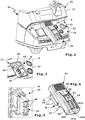
- the module receptacle 34 has, for example, a plug-in receptacle 35, into which a plug-in projection 43 described in more detail in connection with a charging module 60 can be plugged.
- electric module contacts 44 which can come into electrical connection with module contacts 36 of the module receptacle 34, are provided on the plug-in projection 43.
- the module contacts 44 are provided, for example, on a contact carrier 45 which is preferably configured in the form of a plug-in projection and which is provided for insertion into a plug-in receptacle 39 of the module receptacle 34.
- the module contacts 36, 44 are expediently proprietary contacts, that is not about protective contacts such as the example of the connection cable 27 arranged plug.
- the module contacts 36, 44 which for the transmission of electrical energy and / or for the transmission of control signals and / or alarm signals.
- the module receptacle 34 has, for example, a substantially rectangular cross-sectional contour and is designed as a recess.
- the suction device communication module 42 sends, for example via its module contacts 44, switching signals 47 to a control device 37, which in turn controls the suction motor 19, e.g. via suitable circuit breakers, semiconductors or the like.
- a control device 37 which in turn controls the suction motor 19, e.g. via suitable circuit breakers, semiconductors or the like.
- the suction device communication module 42 controls the control device 37 accordingly, which in turn turns on, off or also the suction motor 19 Adjustment of power, for example, the speed is reduced or increased, which is indicated by an arrow 48.
- a variant of the invention can provide that the control device of a suction device integrally a wireless interface, so that a separate suction device communication module, such as the suction device communication module 42, is not necessary.
- the suction device receiver 41r could form part of the control device 37.
- suction device communication device 40 e.g. forms an integral part of the suction device 10.
- the sucker communication device 40 may be e.g. form a part of the control device 37.
- a wireless interface could also be provided between the suction device communication device 40 and the control device 37.
- a puppenzialbuild coupling between the suction device-communication device 40 and the other electrical components of the suction device 10 is preferred, which can be achieved for example by means of optocouplers.
- an external communication device 150 is disposed on board the handheld machine tool 80, or an external communication device 250 is disposed on board the energy storage module 90 and can communicate with the suction device communication device 40 without a lead.
- the external communication devices 150 and 250 may be integral components of the energy storage module 90 and the handheld machine tool 80, respectively. However, it is also a modular concept possible, that is, for example, on the hand-held machine tool 80 and / or the energy storage module 90, a module recording is present, in which the corresponding modular, designed for example as plug-in external communication devices 150 or 250 can be arranged. Furthermore, the external communication devices 150 and / or 250 can also by means of fastening means, for example adhesives, snap-in connection means or the like, subsequently on the energy storage module 90 or the Hand machine tool 80 are arranged. Thus, a retrofit is possible.
- the external communication device 150 includes, for example, a rotational speed sensor 153, which detects a respective rotational speed of the drive motor 81.
- the speed sensor 153 controls an external transmitter 155s including, for example, a Bluetooth transmitter for transmitting control signals 151 through an antenna 156 integrated into the machine housing 83, for example is on, whereupon the suction device communication device 40 turns on the suction motor 19 or sends a switch-on signal to the control device 37.
- the external communication device 150 can control the suction device communication device 40 to an increased speed of the suction motor 19.
- the hand machine tool 80 is turned off, the external communication device 150 controls to turn off the suction motor 19.
- a magnetic sensor instead of or in addition to the rotational speed sensor 153, for example, a magnetic sensor, a Hall sensor or the like could be provided.
- a current sensor may be provided which detects the current flow to the drive motor 81 or not shown working area lighting of the hand-held machine tool 80, which lights up when operating the same, and the external communication device 150 accordingly a control signal 151 to Control of the suction device communication device 40 generated.
- a voltage sensor may also be provided which measures a supply voltage applied to the drive motor 81 or the working field illumination.
- a schematically indicated embodiment provides that, for example, a position sensor and / or a magnetic sensor and / or an electrical switching contact or the like of another sensor 153 'are arranged on a switch 87 which serves for switching on and off the drive motor 81 of the hand-held machine tool 80 is that detects the position of the switch 87 or actuated in dependence on its position, so that the external communication device 150 in response to a position of the switch 87 generates the control signals 51 and thus the suction motor 19 by means of the suction device communication device 40 turns on and / or turns off and / or stops its performance.
- an external communication device can of course also have a plurality of sensors, switching contacts and the like, so that it generates the control signal as a function of at least two sensor signals or signals from switching contacts.
- the external communication device 150 evaluates the sensor signals of the sensors 153 and 153 'and only transmits the control signal 51 for turning on the suction motor 19 when both sensors 153 and 153' indicate that the drive motor 81 of the hand machine tool 80 is running.
- the suction device 10 is still running after a fixed or preferably parameterizable follow-up time, ie the suction motor 19 only after a certain time, when the hand-held power tool 80 is already turned off, also turned off.
- the suction motor 19 even in the suction hose 18 befind Anlagen dust or in the environment around the tool 82 befind Anlagen dust can be sucked, even if the hand-held machine tool 80 is already switched off.
- a switch-on delay time is permanently set or parameterized, so that it turns on the suction motor 19 only after the switch-on delay time, if they by the control signal 51 for switching on the suction motor 19th has been controlled.
- the external communication device 250 forms a component of the energy storage module 90 and comprises a current sensor 253 which comprises a current flow from the energy storage module 90 to the manual power tool 80, in particular its drive motor 81.
- a current sensor 253 detects a current flow
- an external transmitter 255s generates a corresponding control signal 251 for driving the suction device communication device 40 to turn on the suction motor 19.
- the external communication device 250 sends a corresponding shutoff control signal 251, whereupon the suction device communication device 40 turns off the suction motor 19.
- the external communication device 250 is arranged in an energy storage housing of the energy storage module 90.
- an intermediate module 100 so to speak, which is connected between terminal contacts 92 of the energy storage module 90 and the contacts 85 of the hand-held machine tool 80 to detect the flow of current from the energy storage module 90 to the hand-held machine tool 80 and the drive motor 81 and to generate a corresponding control signal 251.
- the intermediate module 100 is indicated.
- a preferred embodiment provides that a suction device communication device and an external communication device, which communicate with each other without line, in the context of a learning process, e.g. a so-called teach function, so to speak, get to know each other.
- a misuse or a misuse can be prevented.
- the external communication device 50 first sends a communication identifier 59 to the suction device receiver 41r, which in turn checks, for example, using a comparison list, if the communication identifier 59 authorizes the external communication device 50 to transmit the control signals 51.
- suction devices for example, if several craftsmen work on a construction site and turn on and off with their hand tools according to the invention suction devices and thus can be prevented that it comes to interference.
- the suction device communication device 40 prefferably be ready to receive the communication identifier 59, for example by pressing an electrical contact of the suction device communication device, not shown in the drawing, thus thus the external communication device 50, 150, 250 as an authorized external Communication recognizes and then from her then the control signals 51, 151, 251 accepted.
- the charging module 60 can also have or form a suction device communication device according to the invention, for example a suction device communication device 140.
- the external communication device 150 may send a malfunction of the handheld machine tool 80 in the frame by means of an external transmitter 155s as a notification signal 101 to the suction device communication device 40 which in turn then receives the notification signal 101 via a suction device receiver 41r and, for example, one optical display 102, for example an LED, to display the message signal 101 drives.
- the external communication device 250 which is for example on board the energy storage module 90
- the charging module 60 which includes the suction device communication device 140
- a wireless communication is appropriate.
- the external communication device 250 by means of an external transmitter 255s to the charging module 60, so the charging device 61, by means of a message signal 201 to report the state of charge of the energy storage module 90.
- the sucker communication device 140 receives the notification signal via a sucker receiver 141r.
- an optical and / or acoustic display 103 can be provided on board the charging device 61, which displays the state of charge of the external energy storage module 90 operated on the hand-held power tool 80.
- the external communication device 250 includes, for example, a measuring device 257 for detecting the state of charge of the energy storage module 90 and for generating the reporting state of the reporting signal 201.
- the aforementioned wireless concept is also applicable in the reverse direction, that is, the suction device communication devices 40, 140 send messages or signals to the external communication devices 50, 150, 250.
- suction device transmitters 41 s and 141 s are provided, which are designed to send control signals and / or signaling signals to the external communication devices 50, 150, 250.
- the suction device transmitter 41s can send a message signal 105 to the external communication device 50, which outputs the content of the signaling signal 105 at optical or acoustic output means 106, which comprise eg an LED.
- the operator can recognize on the basis of this on-site, in the hand-held machine tool 80 signal output that he has to empty, for example, the sump of the suction device 10.
- the control device 37 can therefore generate an alarm signal 105 or a message by means of the suction device communication device 40, which sends it via the suction device transmitter 41s to one or more of the external communication devices 50, 150 or 250.
- the message signal 105 which as indicated may also be a complex message containing a plurality of information or may also comprise a plurality of separate messages, contains, for example, information about the size of the suction flow 20 and / or a suction power of the suction motor 19 and / or information about a level of the dust collecting space 15th
- the external communication devices 50, 150 or 250 may output one or more information of the signaling signal 105, for example to output means 106, which comprise, for example, a light display, for example LEDs, and / or a display and / or a loudspeaker or other acoustic output means. If, for example, the message signal 105 signals that soon the dust collecting space 15 and / or a filter arranged therein, not shown in the drawing, is completely filled and dirty, for example a display LED configured as a warning LED 107 of the external communication device 50 can display this ,
- the external communication device 150 or 250 disposed onboard the energy storage module 90 or the intermediate module 100 or the hand machine tool 80 may further include, for example, a haptic display, a vibration display or the like to output the notification signal 105.
- a haptic display for example, an optical and / or acoustic display 104 and / or a vibration element 109 may be provided as an output means on board the handheld machine tool 80, which at a critical level in the dust collection space 15 and / or at a lower suction power of the suction device 10, which in Signaling signal 105 is signaled vibrates and the operator indicates that he should take care of the suction device 10, so that the desired suction power is available.
- suction device 10 and / or the suction device communication devices 40 or 140 directly influence the function of the handheld machine tool 80 by means of a control signal 108.
- the control device 37 can send information 147 to the suction device communication devices 40 or 140, which generates the control signal 108 corresponding thereto and to the external communication devices 50.
- 150, 250 sends.
- the external communication devices 150 or 250 may then directly affect the operation of the handheld machine tool 80.
- the control signal 108 may instruct to reduce the power of the drive motor 81 or even turn it off completely. As a result, it can be avoided, for example, that the user takes damage to health from swirling particles when the suction device 10 can no longer adequately remove the particles produced by the hand-held machine tool 80.
- the external communications device 250 located onboard the energy storage module 90 may turn off and on the power flow to the handheld machine tool 80 by means of a switching device 258, e.g. after activation by the control signal 108.
- the external communication device 250 may, for example, a wired or preferably wireless interface 259,
- a wired or preferably wireless interface 259 For example, a radio interface for communication with the hand-held machine tool 80, in particular their control 88, for example, to forward the control signal 108 and / or the operating parameters 450, 400 and / or the identifiers 410, 460 to communicate.
- a wired interface 259 may provide that data is digitally transmitted and / or modulated over the supply lines to the handheld machine tool 80.
- the external communication device 150 is directly connected to the controller, for example, an on-board electronics, the hand-held machine tool 80 or forms part of it, so that this can directly influence the operation of the drive motor 81 in this way, so it can turn off, for example ,
- the controller for example, an on-board electronics, the hand-held machine tool 80 or forms part of it.
- the suction device communication devices 40, 140 and / or the external communication devices 50, 150, 250 have, for example, a microprocessor and / or are suitable for the execution of software modules with which the functions explained above or explained below can be implemented.
- the external communication device 50 has a microprocessor 70, which evaluates the sensor signals 54 by means of a program module 71 and controls or realizes, for example, the external transmitter 55s and / or the external receiver 55r.
- the program module 71 like the communication identifier 59, is expediently stored in a memory 72.
- the charging module 60 is for charging the energy storage module 90 or others, not in the drawing illustrated energy storage modules for hand-held machine tools, such as the hand-held machine tool 80 or a in FIG. 8 shown hand-tool 180 in the form of a cordless screwdriver or drill provided.
- the charging module 60 forms a charging device 61 for charging the electrical energy storage module 90.
- the charging module 60 has on its charger housing 62 a holder 63 for holding the energy storage module 90.
- the holder 63 includes, for example, a plug-in projection 64, which can be inserted into a plug-in receptacle 93 of the energy storage housing 91 or the energy storage module 90.
- the holder 63 also includes a plug receptacle or holding receptacle 68 into which a plug projection 94 on an upper side 95 of the energy storage housing 91 can engage.
- the bracket 63 corresponds to the bracket 84 of the handheld machine tool 80 or 180, i. it is designed for positive reception of the energy storage housing 91.
- electrical charging contacts 65 are provided for providing a charging voltage L for the electrical energy storage module 90.
- the charging voltage L is for example a DC voltage in a range of 5 V to 25 V.
- the charging module 60 detection means 66 to detect the respective type of the energy storage module 90 and accordingly set the charging voltage L. If, for example, a 12 V energy storage module is connected, the charging voltage L is set correspondingly lower, while for an energy storage module with a rated voltage of 18 V, a correspondingly higher charging voltage L is inserted.
- the detection means 66 include, for example, electrical means, optical means, or the like. It is also possible for the detection means 66 to include, for example, a bus interface in order to communicate with a bus coupler on board the energy storage module 90 and thus to acquire data of the energy storage module 90, for example its charge state, nominal voltage or the like.
- the charging device 61 can convert a supply voltage V provided, for example, from the supply network N to the charging voltage L.
- monitoring means 75 are advantageously provided for monitoring the charging voltage L and / or for monitoring a charging state of the energy storage module 90, so that it is optimally charged.
- the monitoring means 75 and / or detection means 66 and / or the adaptation means 67 comprise, for example, a microprocessor 76 which executes program code of software modules, for example a software module 78 stored in a memory 77.
- a microprocessor 76 which executes program code of software modules, for example a software module 78 stored in a memory 77.
- the charger housing 62 is partially configured similar to the suction device communication module 42, thus also has a plug projection 43, are provided on the module contacts 44 for establishing an electrical connection with the module contacts 36 of the module receptacle 34.
- adjustment means 67 from the suction device 10, ie, for example, via the connecting cable 27, are supplied with electrical energy to provide the charging voltage L.
- An additional fixation of the loading module 60 on the sucker housing 11 or the module receptacle 34 can be effected for example by means of screws 69, which can be screwed into corresponding screw openings 38 of the module receptacle 34.
- a magnetic stop, latching or the like of the loading module 60 on the sucker housing 11 is readily possible, but not shown in the drawing.
- the suction device communication module 42 can expediently also have corresponding holding means (screws, magnets, latching means) in order to find a secure hold in the module receptacle 34.
- the charging module 60 and the charging device 61 forms an integral part of the suction device 10, that is, for example, the charger housing 62 and the nipple housing 11 are integral.
- a holder in the manner of the holder 63 and charging contacts in the nature of the charging contacts 65 may be disposed at another location of the sucker housing 11, for example, above in the area of the receptacle 28, where the energy storage module to be charged can be accommodated protected, that is less exposed is than in the area of the control wall 22.
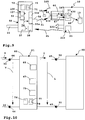
- the suction device communication device 140 formed by the loading module 60 has, for example, a suction device receiver 141r. Via the module contacts 36, the charging module 60 is supplied with electrical energy, for example a supply voltage V. A current sensor 49 on board the suction device 10, for example as a component or in combination with the control device 37, for example, detects whether an electrical current flows through the module contacts 36.
- the charging module 60 When the charging module 60 receives a control signal 51, 151, 251 for switching on the suction motor 19 via its suction device receiver 141r and an antenna 146 integrated, for example, in the charger housing 62, it begins charging the energy storage module 90, ie it generates the supply voltage V Charging voltage L, so that a charging current I flows. An input current E necessary for providing the charging current I is detected by the current sensor 49.
- the suction device 10 thus recognizes that an electrical load requires power and then turns on the naturally aspirated motor 19 in a manner known per se.
- the suction device communication device 140 or the charging module 60 reduces the power supply to the energy storage module 90 or switches off the charging process, so that the input side (supply voltage V) no input current E detectable by the current sensor 49 or an input current E lying below a detection threshold flows, and thus, for example, the control device 37 shuts off the suction motor 19.
- the charging module 60 can virtually simulate a network-connected electric hand-held machine tool, which is supplied via the suction device 10 with electrical energy - which is actually not the case.
- the charging device 61 is supplied by the energy storage 26 on board the suction device 10 with electrical energy.
- the control device 37 controls the provision of electrical energy to the module contacts 36. It is preferably provided that the control device 37, for example, the power output to the Module contacts 36 lowers when the suction motor 19 is running, then lifting again. Thus, for example, a power supply of the suction device 10, which provides the charging voltage L, less heavily loaded.
- the suction device communication devices 40 and / or 140 and the external communication devices 50, 150, 250 located on or connected to the suction device 10 are also suitable for a log-on procedure in which the suction device 10 has at least one operating parameter 400 and / or at least one Identification code 410 sends to the external device, for example the handheld machine tool 80 and / or its energy storage module 90 and / or in the reverse direction the device to be connected to the suction device 10, for example the handheld machine tool 80 or its energy storage module 90 at least one operating parameter 450 and / or or at least one identifier 460 sends to the suction device 10, so that only matching pairs of suction device and hand machine tool are used and / or the operating parameters of the suction device 10 and the hand-held machine tool 80 or 180 are set so that an optimal operation of respective hand-who Machine 80 or 180 on the suction device 10 is possible.
- the suction device 10 has at least one operating parameter 400 and / or at least one Identification code 410 sends to the external device, for example the handheld machine tool 80 and
- the suction power of the suction device 10 is insufficient for the operation of the manual power tool, it can be prevented from using the suction device 10 in conjunction with the manual power tool 80 by the procedure described in detail below.
- the suction power is sufficient for, for example, the hand machine tool 180, the suction apparatus 10 and the hand machine tool 180 may be used together.
- suction device 10 and the respective connected hand-held machine tool 80 or 180 coordinate their respective performances to each other by the one device registers with the other device and / or vice versa.
- a wireless communication between the hand-held power tool 80 and 180 on the one hand and the suction device 10, in particular their suction device communication devices 40, 140 is appropriate, but does not preclude that in particular for the registration procedure or identification procedure described below, but also the transmission of message signals and / or control signals, a wired communication, at least in one direction (from the suction device to the hand-machine tool or vice versa) within the scope of the invention.
- a wired communication at least in one direction (from the suction device to the hand-machine tool or vice versa) within the scope of the invention.
- in one direction that is, for example, from the suction device to the hand-held machine tool cable bound to be communicated in the reverse direction without wires or vice versa.
- At least one communication line 300 for example, an electrical line and / or an optical conductor, on the one hand, for example, the suction device communication devices 40 and / or the controller 37 or other component on board the suction device 10 is connected to communicate with the handheld machine tool 80 or 180.
- the external communication device 150 or 250 may be connected to the at least one communication line 300.
- the external communication device 150 or 250 sends the identification tag 460 identifying the handheld machine tool 80 to the suction device 10.
- the suction device communication device 40 receives the identification code 460 and forwards it, for example, to the control device 37, which recognizes, for example, the type of the hand-held machine tool 80, for example, what amount of particles is to be expected from this hand-held machine tool 80, which suction power corresponding to the identification code 460 is to be provided by the suction device 10 or the like.
- the control device 37 accordingly sets the function of the suction device 10, for example, such that the suction power of the suction motor 19 is adjustable on the adjusting switch 24, but not below a limit value which enables reliable extraction of the particles which the hand-held machine tool 80 generates ,
- control device 37 can check whether an operation of the hand-held machine tool 80 with the suction device 10 is even possible if at least one criterion is met. If, for example, it should be noted that the suction device 10 is intended to provide explosion protection in connection with the respective hand-held machine tool and / or at least one predetermined suction power of the suction device 10 is required so that the at least one criterion is met, the control device 37 can determine whether the identification tag 460 is indicated in a table 430 containing a plurality of identification tags. If so, the controller 37 releases the suction device 10 for operation with the hand machine tool 80.
- the nature of the particles may also be different, including, for example, larger chips or smaller chips. Accordingly, it is expedient for the handheld machine tool 80, for example as an operating parameter 450, to send information about the tool 82 used to the suction device communication devices 40 or 140.
- the control device 37 can, for example, set cleaning intervals of a cleaning device 9 which cleans a filter 8, which precedes the suction motor 19.
- the suction device 10 logs on, so to speak, before the start of an operation.
- the suction device communication device 40 sends an identification code 410 of the suction device 10 and / or at least one operating parameter 400 to the manual machine tool 80.
- a controller 88 on-board the handheld machine tool 80 checks, based on a check table, whether the identification tag 410 classifies the suction device 10 so that it can be used in conjunction with the handheld machine tool 80. Only then does the controller 88 release the drive motor 81. Otherwise, the controller 88 blocks the drive motor 81, so that, for example, health impairments of a user of the hand-held machine tool 80 can be avoided by non-aspirated particles.
- the suction device 10 can inform the hand-held machine tool 80, for example, which suction power can be available.
- the hand machine tool 80 then reduces, for example Maximum speed of the drive motor 81, so that even with a maximum switchable at the switch 87 speed of the drive motor 81, the suction of the suction device 10 is sufficient to reliably suck all accumulating particles or at least substantially all particles from the working area of the hand-held machine tool 80.
- the external communication devices 150 or 250 and / or the suction device communication devices 40 or 140 based on the respectively received identification code when the 410, 460 and / or the received operating parameters 400, 450 directly generate control signals and / or alarm signals and to the other Send communication equipment.
- the external communication devices 150 and / or 250 can determine from the identification code 410, for example, that the suction device 10 has to provide a specific output and accordingly sends a control signal 351 that controls the suction device 10 instructed to set a particular power level as a minimum adjustable power level on the control switch 24.
- a control signal 351 that controls the suction device 10 instructed to set a particular power level as a minimum adjustable power level on the control switch 24.
- the control signal 351 and a message signal 352 are generated, which is displayed for example by the display 102.
- the suction device 10 or the suction device communication devices 40, 140 can also be designed in this way.
- the suction device communication devices 40, 140 and / or the suction device 10 for example the control device 37, use the identification code 460 or the operating parameter 450 to determine which rotational speeds of the drive motor 81 of the handheld machine tool 80 are adjustable or adjustable and accordingly sends a control signal 353 and / or a Notification signal 354 to the external communication devices 150 or 250.
- the control signal 353 instructs them to tell, for example, the control device 88 which services of the drive motor 81 should be adjustable at the switch 87.
- the information of the notification signal 354 is displayed on the display 104, for example, so that the operator knows which power ranges to be set on the hand machine tool 80 and / or which tools are usable or the like.
Landscapes
- Engineering & Computer Science (AREA)
- Mechanical Engineering (AREA)
- Power Engineering (AREA)
- Auxiliary Devices For Machine Tools (AREA)
- Charge And Discharge Circuits For Batteries Or The Like (AREA)
Priority Applications (1)
| Application Number | Priority Date | Filing Date | Title |
|---|---|---|---|
| EP24177522.0A EP4398451A3 (fr) | 2012-02-17 | 2013-02-08 | Appareil d'aspiration doté d'un dispositif de charge |
Applications Claiming Priority (2)
| Application Number | Priority Date | Filing Date | Title |
|---|---|---|---|
| DE102012003075 | 2012-02-17 | ||
| EP13000691.9A EP2628428B1 (fr) | 2012-02-17 | 2013-02-08 | Appareil d'aspiration avec un dispositif de chargement |
Related Parent Applications (3)
| Application Number | Title | Priority Date | Filing Date |
|---|---|---|---|
| EP13000691.9A Division-Into EP2628428B1 (fr) | 2012-02-17 | 2013-02-08 | Appareil d'aspiration avec un dispositif de chargement |
| EP13000691.9A Division EP2628428B1 (fr) | 2012-02-17 | 2013-02-08 | Appareil d'aspiration avec un dispositif de chargement |
| EP13000691.9A Previously-Filed-Application EP2628428B1 (fr) | 2012-02-17 | 2013-02-08 | Appareil d'aspiration avec un dispositif de chargement |
Related Child Applications (2)
| Application Number | Title | Priority Date | Filing Date |
|---|---|---|---|
| EP24177522.0A Division EP4398451A3 (fr) | 2012-02-17 | 2013-02-08 | Appareil d'aspiration doté d'un dispositif de charge |
| EP24177522.0A Division-Into EP4398451A3 (fr) | 2012-02-17 | 2013-02-08 | Appareil d'aspiration doté d'un dispositif de charge |
Publications (2)
| Publication Number | Publication Date |
|---|---|
| EP3524110A1 true EP3524110A1 (fr) | 2019-08-14 |
| EP3524110B1 EP3524110B1 (fr) | 2024-07-17 |
Family
ID=47683507
Family Applications (3)
| Application Number | Title | Priority Date | Filing Date |
|---|---|---|---|
| EP24177522.0A Pending EP4398451A3 (fr) | 2012-02-17 | 2013-02-08 | Appareil d'aspiration doté d'un dispositif de charge |
| EP19164014.3A Active EP3524110B1 (fr) | 2012-02-17 | 2013-02-08 | Appareil d'aspiration doté d'un dispositif de recharge |
| EP13000691.9A Active EP2628428B1 (fr) | 2012-02-17 | 2013-02-08 | Appareil d'aspiration avec un dispositif de chargement |
Family Applications Before (1)
| Application Number | Title | Priority Date | Filing Date |
|---|---|---|---|
| EP24177522.0A Pending EP4398451A3 (fr) | 2012-02-17 | 2013-02-08 | Appareil d'aspiration doté d'un dispositif de charge |
Family Applications After (1)
| Application Number | Title | Priority Date | Filing Date |
|---|---|---|---|
| EP13000691.9A Active EP2628428B1 (fr) | 2012-02-17 | 2013-02-08 | Appareil d'aspiration avec un dispositif de chargement |
Country Status (4)
| Country | Link |
|---|---|
| EP (3) | EP4398451A3 (fr) |
| DE (1) | DE102013002251A1 (fr) |
| DK (1) | DK3524110T3 (fr) |
| FI (1) | FI3524110T3 (fr) |
Families Citing this family (14)
| Publication number | Priority date | Publication date | Assignee | Title |
|---|---|---|---|---|
| CN204833259U (zh) | 2012-07-17 | 2015-12-02 | 米沃奇电动工具公司 | 电动工具及电动工具系统 |
| JP2015154600A (ja) | 2014-02-14 | 2015-08-24 | 株式会社マキタ | 電動工具用電池パックの充電装置 |
| DE102015226190A1 (de) * | 2015-12-21 | 2017-06-22 | Robert Bosch Gmbh | System mit zumindest einer Werkzeugmaschine und mit zumindest einer mobilen Sensorvorrichtung |
| DE102016120329A1 (de) * | 2016-10-25 | 2018-04-26 | Festool Gmbh | Anschlussvorrichtung eines Elektrogeräts oder eines Energiespeichers |
| WO2019009938A1 (fr) | 2017-07-05 | 2019-01-10 | Milwaukee Electric Tool Corporation | Adaptateurs pour communication entre des outils électriques |
| DE102017115436A1 (de) * | 2017-07-10 | 2019-01-10 | Metabowerke Gmbh | Verfahren zur Benutzersteuerung eines Mehrzweckstaubsaugers |
| DE102017218852A1 (de) | 2017-10-23 | 2019-04-25 | Robert Bosch Gmbh | Absauganschlussadapter |
| US11011053B2 (en) | 2018-07-31 | 2021-05-18 | Tti (Macao Commercial Offshore) Limited | Systems and methods for remote power tool device control |
| CN111660180B (zh) * | 2019-02-19 | 2023-09-08 | 创科无线普通合伙 | 用于多个电气装置以实现同步操作的适配器 |
| DE102019106292A1 (de) * | 2019-03-12 | 2020-09-17 | Vorwerk & Co. Interholding Gmbh | Bodenbearbeitungsgerät mit einem Akkumulator und System aus einem Bodenbearbeitungsgerät und mindestens einem weiteren Akkumulator |
| DE102020200483A1 (de) | 2020-01-16 | 2021-07-22 | Robert Bosch Gesellschaft mit beschränkter Haftung | Verfahren zur Steuerung eines Sauggeräts |
| EP4247228A4 (fr) | 2020-11-19 | 2025-08-27 | Milwaukee Electric Tool Corp | Dépoussiéreur portatif |
| US12273937B2 (en) | 2021-02-16 | 2025-04-08 | Milwaukee Electric Tool Corporation | Communication between a wireless dust extractor and a power tool |
| EP4091514B1 (fr) * | 2021-05-20 | 2023-07-12 | Guido Valentini | Dispositif d'aspiration et tuyau d'aspiration pour un tel dispositif d'aspiration |
Citations (6)
| Publication number | Priority date | Publication date | Assignee | Title |
|---|---|---|---|---|
| US20040088817A1 (en) * | 2002-11-12 | 2004-05-13 | Cochran John R. | AC/DC hand portable wet/dry vacuum having improved portability and convenience |
| WO2006084561A1 (fr) * | 2005-02-11 | 2006-08-17 | Alfred Kärcher Gmbh & Co. Kg | Aspirateur a compartiment batterie |
| DE102008054489A1 (de) * | 2008-12-10 | 2010-06-17 | Hilti Aktiengesellschaft | Werkzeugsystem |
| EP2229857A2 (fr) * | 2009-03-21 | 2010-09-22 | Festool GmbH | Dispositif d'aspiration doté d'un module de fonctionnement |
| US20110239398A1 (en) * | 2010-04-05 | 2011-10-06 | Makita Corporation | Dust collecting devices |
| EP2451001A1 (fr) * | 2010-11-08 | 2012-05-09 | HILTI Aktiengesellschaft | Appareil électrique mobile doté d'un affichage d'état de chargement et accumulateur associé |
-
2013
- 2013-02-08 EP EP24177522.0A patent/EP4398451A3/fr active Pending
- 2013-02-08 DK DK19164014.3T patent/DK3524110T3/da active
- 2013-02-08 FI FIEP19164014.3T patent/FI3524110T3/fi active
- 2013-02-08 EP EP19164014.3A patent/EP3524110B1/fr active Active
- 2013-02-08 DE DE102013002251A patent/DE102013002251A1/de not_active Withdrawn
- 2013-02-08 EP EP13000691.9A patent/EP2628428B1/fr active Active
Patent Citations (7)
| Publication number | Priority date | Publication date | Assignee | Title |
|---|---|---|---|---|
| US20040088817A1 (en) * | 2002-11-12 | 2004-05-13 | Cochran John R. | AC/DC hand portable wet/dry vacuum having improved portability and convenience |
| WO2006084561A1 (fr) * | 2005-02-11 | 2006-08-17 | Alfred Kärcher Gmbh & Co. Kg | Aspirateur a compartiment batterie |
| DE102008054489A1 (de) * | 2008-12-10 | 2010-06-17 | Hilti Aktiengesellschaft | Werkzeugsystem |
| EP2229857A2 (fr) * | 2009-03-21 | 2010-09-22 | Festool GmbH | Dispositif d'aspiration doté d'un module de fonctionnement |
| DE102009015642A1 (de) | 2009-03-21 | 2010-09-30 | Festool Gmbh | Sauggerät mit Funktionsmodul |
| US20110239398A1 (en) * | 2010-04-05 | 2011-10-06 | Makita Corporation | Dust collecting devices |
| EP2451001A1 (fr) * | 2010-11-08 | 2012-05-09 | HILTI Aktiengesellschaft | Appareil électrique mobile doté d'un affichage d'état de chargement et accumulateur associé |
Also Published As
| Publication number | Publication date |
|---|---|
| DE102013002251A1 (de) | 2013-08-22 |
| DK3524110T3 (da) | 2024-09-02 |
| EP2628428B1 (fr) | 2019-05-22 |
| EP4398451A2 (fr) | 2024-07-10 |
| EP2628428A2 (fr) | 2013-08-21 |
| EP2628428A3 (fr) | 2018-01-17 |
| EP3524110B1 (fr) | 2024-07-17 |
| FI3524110T3 (fi) | 2024-07-23 |
| EP4398451A3 (fr) | 2024-10-02 |
Similar Documents
| Publication | Publication Date | Title |
|---|---|---|
| EP2628428B1 (fr) | Appareil d'aspiration avec un dispositif de chargement | |
| EP2628431B1 (fr) | Procédé d'identification pour un appareil d'aspiration et une machine-outil manuelle | |
| EP2628427B1 (fr) | Appareil d'aspiration avec émetteur d'appareil d'aspiration et installation de communication externe à cet effet | |
| DE102012003073A1 (de) | Sauggerät mit einer Sauggerät-Kommunikationseinrichtung | |
| EP3625782B1 (fr) | Dispositif de configuration pour un système avec outil de machine et aspirateur | |
| EP3635703B1 (fr) | Dispositif électrique pour commander un aspirateur | |
| EP2878249B1 (fr) | Aspirateur multifonction | |
| EP3635704B2 (fr) | Dispositif électrique en tant que composant de système pour commander un aspirateur | |
| DE102013222313A1 (de) | Gerätesystem | |
| DE102017205072A1 (de) | Sauggerät mit Steckmodul | |
| DE102017218852A1 (de) | Absauganschlussadapter | |
| EP3913595A1 (fr) | Module d'accumulation d'énergie pour une machine-outil portative | |
| EP3813622B1 (fr) | Système d'appareil d'aspiration et outil à main et procédé d'operation du système | |
| EP3687358A1 (fr) | Aspirateur |
Legal Events
| Date | Code | Title | Description |
|---|---|---|---|
| PUAI | Public reference made under article 153(3) epc to a published international application that has entered the european phase |
Free format text: ORIGINAL CODE: 0009012 |
|
| STAA | Information on the status of an ep patent application or granted ep patent |
Free format text: STATUS: THE APPLICATION HAS BEEN PUBLISHED |
|
| AC | Divisional application: reference to earlier application |
Ref document number: 2628428 Country of ref document: EP Kind code of ref document: P |
|
| AK | Designated contracting states |
Kind code of ref document: A1 Designated state(s): AL AT BE BG CH CY CZ DE DK EE ES FI FR GB GR HR HU IE IS IT LI LT LU LV MC MK MT NL NO PL PT RO RS SE SI SK SM TR |
|
| STAA | Information on the status of an ep patent application or granted ep patent |
Free format text: STATUS: REQUEST FOR EXAMINATION WAS MADE |
|
| 17P | Request for examination filed |
Effective date: 20200123 |
|
| RBV | Designated contracting states (corrected) |
Designated state(s): AL AT BE BG CH CY CZ DE DK EE ES FI FR GB GR HR HU IE IS IT LI LT LU LV MC MK MT NL NO PL PT RO RS SE SI SK SM TR |
|
| GRAP | Despatch of communication of intention to grant a patent |
Free format text: ORIGINAL CODE: EPIDOSNIGR1 |
|
| STAA | Information on the status of an ep patent application or granted ep patent |
Free format text: STATUS: GRANT OF PATENT IS INTENDED |
|
| INTG | Intention to grant announced |
Effective date: 20240215 |
|
| P01 | Opt-out of the competence of the unified patent court (upc) registered |
Effective date: 20240311 |
|
| GRAS | Grant fee paid |
Free format text: ORIGINAL CODE: EPIDOSNIGR3 |
|
| GRAA | (expected) grant |
Free format text: ORIGINAL CODE: 0009210 |
|
| STAA | Information on the status of an ep patent application or granted ep patent |
Free format text: STATUS: THE PATENT HAS BEEN GRANTED |
|
| AC | Divisional application: reference to earlier application |
Ref document number: 2628428 Country of ref document: EP Kind code of ref document: P |
|
| AK | Designated contracting states |
Kind code of ref document: B1 Designated state(s): AL AT BE BG CH CY CZ DE DK EE ES FI FR GB GR HR HU IE IS IT LI LT LU LV MC MK MT NL NO PL PT RO RS SE SI SK SM TR |
|
| REG | Reference to a national code |
Ref country code: FI Ref legal event code: FGE |
|
| REG | Reference to a national code |
Ref country code: CH Ref legal event code: EP |
|
| REG | Reference to a national code |
Ref country code: DE Ref legal event code: R096 Ref document number: 502013016532 Country of ref document: DE |
|
| REG | Reference to a national code |
Ref country code: IE Ref legal event code: FG4D Free format text: LANGUAGE OF EP DOCUMENT: GERMAN |
|
| REG | Reference to a national code |
Ref country code: NL Ref legal event code: FP |
|
| REG | Reference to a national code |
Ref country code: DK Ref legal event code: T3 Effective date: 20240827 |
|
| REG | Reference to a national code |
Ref country code: LT Ref legal event code: MG9D |
|
| PG25 | Lapsed in a contracting state [announced via postgrant information from national office to epo] |
Ref country code: PT Free format text: LAPSE BECAUSE OF FAILURE TO SUBMIT A TRANSLATION OF THE DESCRIPTION OR TO PAY THE FEE WITHIN THE PRESCRIBED TIME-LIMIT Effective date: 20241118 |
|
| PG25 | Lapsed in a contracting state [announced via postgrant information from national office to epo] |
Ref country code: PT Free format text: LAPSE BECAUSE OF FAILURE TO SUBMIT A TRANSLATION OF THE DESCRIPTION OR TO PAY THE FEE WITHIN THE PRESCRIBED TIME-LIMIT Effective date: 20241118 |
|
| PG25 | Lapsed in a contracting state [announced via postgrant information from national office to epo] |
Ref country code: NO Free format text: LAPSE BECAUSE OF FAILURE TO SUBMIT A TRANSLATION OF THE DESCRIPTION OR TO PAY THE FEE WITHIN THE PRESCRIBED TIME-LIMIT Effective date: 20241017 |
|
| PG25 | Lapsed in a contracting state [announced via postgrant information from national office to epo] |
Ref country code: GR Free format text: LAPSE BECAUSE OF FAILURE TO SUBMIT A TRANSLATION OF THE DESCRIPTION OR TO PAY THE FEE WITHIN THE PRESCRIBED TIME-LIMIT Effective date: 20241018 Ref country code: PL Free format text: LAPSE BECAUSE OF FAILURE TO SUBMIT A TRANSLATION OF THE DESCRIPTION OR TO PAY THE FEE WITHIN THE PRESCRIBED TIME-LIMIT Effective date: 20240717 |
|
| PG25 | Lapsed in a contracting state [announced via postgrant information from national office to epo] |
Ref country code: BG Free format text: LAPSE BECAUSE OF FAILURE TO SUBMIT A TRANSLATION OF THE DESCRIPTION OR TO PAY THE FEE WITHIN THE PRESCRIBED TIME-LIMIT Effective date: 20240717 |
|
| PG25 | Lapsed in a contracting state [announced via postgrant information from national office to epo] |
Ref country code: LV Free format text: LAPSE BECAUSE OF FAILURE TO SUBMIT A TRANSLATION OF THE DESCRIPTION OR TO PAY THE FEE WITHIN THE PRESCRIBED TIME-LIMIT Effective date: 20240717 |
|
| PG25 | Lapsed in a contracting state [announced via postgrant information from national office to epo] |
Ref country code: IS Free format text: LAPSE BECAUSE OF FAILURE TO SUBMIT A TRANSLATION OF THE DESCRIPTION OR TO PAY THE FEE WITHIN THE PRESCRIBED TIME-LIMIT Effective date: 20241117 |
|
| PG25 | Lapsed in a contracting state [announced via postgrant information from national office to epo] |
Ref country code: HR Free format text: LAPSE BECAUSE OF FAILURE TO SUBMIT A TRANSLATION OF THE DESCRIPTION OR TO PAY THE FEE WITHIN THE PRESCRIBED TIME-LIMIT Effective date: 20240717 |
|
| PG25 | Lapsed in a contracting state [announced via postgrant information from national office to epo] |
Ref country code: ES Free format text: LAPSE BECAUSE OF FAILURE TO SUBMIT A TRANSLATION OF THE DESCRIPTION OR TO PAY THE FEE WITHIN THE PRESCRIBED TIME-LIMIT Effective date: 20240717 Ref country code: RS Free format text: LAPSE BECAUSE OF FAILURE TO SUBMIT A TRANSLATION OF THE DESCRIPTION OR TO PAY THE FEE WITHIN THE PRESCRIBED TIME-LIMIT Effective date: 20241017 |
|
| PG25 | Lapsed in a contracting state [announced via postgrant information from national office to epo] |
Ref country code: RS Free format text: LAPSE BECAUSE OF FAILURE TO SUBMIT A TRANSLATION OF THE DESCRIPTION OR TO PAY THE FEE WITHIN THE PRESCRIBED TIME-LIMIT Effective date: 20241017 Ref country code: PL Free format text: LAPSE BECAUSE OF FAILURE TO SUBMIT A TRANSLATION OF THE DESCRIPTION OR TO PAY THE FEE WITHIN THE PRESCRIBED TIME-LIMIT Effective date: 20240717 Ref country code: NO Free format text: LAPSE BECAUSE OF FAILURE TO SUBMIT A TRANSLATION OF THE DESCRIPTION OR TO PAY THE FEE WITHIN THE PRESCRIBED TIME-LIMIT Effective date: 20241017 Ref country code: LV Free format text: LAPSE BECAUSE OF FAILURE TO SUBMIT A TRANSLATION OF THE DESCRIPTION OR TO PAY THE FEE WITHIN THE PRESCRIBED TIME-LIMIT Effective date: 20240717 Ref country code: IS Free format text: LAPSE BECAUSE OF FAILURE TO SUBMIT A TRANSLATION OF THE DESCRIPTION OR TO PAY THE FEE WITHIN THE PRESCRIBED TIME-LIMIT Effective date: 20241117 Ref country code: HR Free format text: LAPSE BECAUSE OF FAILURE TO SUBMIT A TRANSLATION OF THE DESCRIPTION OR TO PAY THE FEE WITHIN THE PRESCRIBED TIME-LIMIT Effective date: 20240717 Ref country code: GR Free format text: LAPSE BECAUSE OF FAILURE TO SUBMIT A TRANSLATION OF THE DESCRIPTION OR TO PAY THE FEE WITHIN THE PRESCRIBED TIME-LIMIT Effective date: 20241018 Ref country code: ES Free format text: LAPSE BECAUSE OF FAILURE TO SUBMIT A TRANSLATION OF THE DESCRIPTION OR TO PAY THE FEE WITHIN THE PRESCRIBED TIME-LIMIT Effective date: 20240717 Ref country code: BG Free format text: LAPSE BECAUSE OF FAILURE TO SUBMIT A TRANSLATION OF THE DESCRIPTION OR TO PAY THE FEE WITHIN THE PRESCRIBED TIME-LIMIT Effective date: 20240717 |
|
| PG25 | Lapsed in a contracting state [announced via postgrant information from national office to epo] |
Ref country code: RO Free format text: LAPSE BECAUSE OF FAILURE TO SUBMIT A TRANSLATION OF THE DESCRIPTION OR TO PAY THE FEE WITHIN THE PRESCRIBED TIME-LIMIT Effective date: 20240717 Ref country code: SM Free format text: LAPSE BECAUSE OF FAILURE TO SUBMIT A TRANSLATION OF THE DESCRIPTION OR TO PAY THE FEE WITHIN THE PRESCRIBED TIME-LIMIT Effective date: 20240717 |
|
| REG | Reference to a national code |
Ref country code: DE Ref legal event code: R097 Ref document number: 502013016532 Country of ref document: DE |
|
| PG25 | Lapsed in a contracting state [announced via postgrant information from national office to epo] |
Ref country code: EE Free format text: LAPSE BECAUSE OF FAILURE TO SUBMIT A TRANSLATION OF THE DESCRIPTION OR TO PAY THE FEE WITHIN THE PRESCRIBED TIME-LIMIT Effective date: 20240717 |
|
| PG25 | Lapsed in a contracting state [announced via postgrant information from national office to epo] |
Ref country code: CZ Free format text: LAPSE BECAUSE OF FAILURE TO SUBMIT A TRANSLATION OF THE DESCRIPTION OR TO PAY THE FEE WITHIN THE PRESCRIBED TIME-LIMIT Effective date: 20240717 |
|
| PG25 | Lapsed in a contracting state [announced via postgrant information from national office to epo] |
Ref country code: SK Free format text: LAPSE BECAUSE OF FAILURE TO SUBMIT A TRANSLATION OF THE DESCRIPTION OR TO PAY THE FEE WITHIN THE PRESCRIBED TIME-LIMIT Effective date: 20240717 |
|
| PLBE | No opposition filed within time limit |
Free format text: ORIGINAL CODE: 0009261 |
|
| STAA | Information on the status of an ep patent application or granted ep patent |
Free format text: STATUS: NO OPPOSITION FILED WITHIN TIME LIMIT |
|
| 26N | No opposition filed |
Effective date: 20250422 |
|
| PG25 | Lapsed in a contracting state [announced via postgrant information from national office to epo] |
Ref country code: SE Free format text: LAPSE BECAUSE OF FAILURE TO SUBMIT A TRANSLATION OF THE DESCRIPTION OR TO PAY THE FEE WITHIN THE PRESCRIBED TIME-LIMIT Effective date: 20240717 |
|
| PG25 | Lapsed in a contracting state [announced via postgrant information from national office to epo] |
Ref country code: MC Free format text: LAPSE BECAUSE OF FAILURE TO SUBMIT A TRANSLATION OF THE DESCRIPTION OR TO PAY THE FEE WITHIN THE PRESCRIBED TIME-LIMIT Effective date: 20240717 |
|
| REG | Reference to a national code |
Ref country code: CH Ref legal event code: PL |
|
| PG25 | Lapsed in a contracting state [announced via postgrant information from national office to epo] |
Ref country code: FI Free format text: LAPSE BECAUSE OF NON-PAYMENT OF DUE FEES Effective date: 20250208 |
|
| PG25 | Lapsed in a contracting state [announced via postgrant information from national office to epo] |
Ref country code: LU Free format text: LAPSE BECAUSE OF NON-PAYMENT OF DUE FEES Effective date: 20250208 |
|
| PG25 | Lapsed in a contracting state [announced via postgrant information from national office to epo] |
Ref country code: CH Free format text: LAPSE BECAUSE OF NON-PAYMENT OF DUE FEES Effective date: 20250228 |
|
| REG | Reference to a national code |
Ref country code: BE Ref legal event code: MM Effective date: 20250228 |
|
| PGFP | Annual fee paid to national office [announced via postgrant information from national office to epo] |
Ref country code: GB Payment date: 20251210 Year of fee payment: 14 |
|
| PG25 | Lapsed in a contracting state [announced via postgrant information from national office to epo] |
Ref country code: IT Free format text: LAPSE BECAUSE OF NON-PAYMENT OF DUE FEES Effective date: 20250208 |
|
| PGFP | Annual fee paid to national office [announced via postgrant information from national office to epo] |
Ref country code: FR Payment date: 20251210 Year of fee payment: 14 |
|
| PG25 | Lapsed in a contracting state [announced via postgrant information from national office to epo] |
Ref country code: BE Free format text: LAPSE BECAUSE OF NON-PAYMENT OF DUE FEES Effective date: 20250228 |
|
| PG25 | Lapsed in a contracting state [announced via postgrant information from national office to epo] |
Ref country code: IE Free format text: LAPSE BECAUSE OF NON-PAYMENT OF DUE FEES Effective date: 20250208 |
|
| PGFP | Annual fee paid to national office [announced via postgrant information from national office to epo] |
Ref country code: NL Payment date: 20260218 Year of fee payment: 14 |
|
| PGFP | Annual fee paid to national office [announced via postgrant information from national office to epo] |
Ref country code: DE Payment date: 20251210 Year of fee payment: 14 Ref country code: DK Payment date: 20260220 Year of fee payment: 14 |
|
| PG25 | Lapsed in a contracting state [announced via postgrant information from national office to epo] |
Ref country code: AT Free format text: LAPSE BECAUSE OF NON-PAYMENT OF DUE FEES Effective date: 20250208 |
|
| PG25 | Lapsed in a contracting state [announced via postgrant information from national office to epo] |
Ref country code: IT Free format text: LAPSE BECAUSE OF NON-PAYMENT OF DUE FEES Effective date: 20250208 |
|
| PGFP | Annual fee paid to national office [announced via postgrant information from national office to epo] |
Ref country code: IT Payment date: 20260224 Year of fee payment: 14 |
|
| PGRI | Patent reinstated in contracting state [announced from national office to epo] |
Ref country code: IT Effective date: 20250630 |
|
| REG | Reference to a national code |
Ref country code: AT Ref legal event code: MM01 Ref document number: 1703317 Country of ref document: AT Kind code of ref document: T Effective date: 20250208 |