EP3524331A1 - Vorrichtung zur thermischen behandlung von viskosem material, insbesondere zur thermischen auftrennung von in viskosem material enthaltenen materialkomponenten - Google Patents
Vorrichtung zur thermischen behandlung von viskosem material, insbesondere zur thermischen auftrennung von in viskosem material enthaltenen materialkomponenten Download PDFInfo
- Publication number
- EP3524331A1 EP3524331A1 EP18156079.8A EP18156079A EP3524331A1 EP 3524331 A1 EP3524331 A1 EP 3524331A1 EP 18156079 A EP18156079 A EP 18156079A EP 3524331 A1 EP3524331 A1 EP 3524331A1
- Authority
- EP
- European Patent Office
- Prior art keywords
- elements
- rotor
- treatment
- conveying
- housing
- Prior art date
- Legal status (The legal status is an assumption and is not a legal conclusion. Google has not performed a legal analysis and makes no representation as to the accuracy of the status listed.)
- Granted
Links
Images


Classifications
-
- B—PERFORMING OPERATIONS; TRANSPORTING
- B01—PHYSICAL OR CHEMICAL PROCESSES OR APPARATUS IN GENERAL
- B01J—CHEMICAL OR PHYSICAL PROCESSES, e.g. CATALYSIS OR COLLOID CHEMISTRY; THEIR RELEVANT APPARATUS
- B01J19/00—Chemical, physical or physico-chemical processes in general; Their relevant apparatus
- B01J19/18—Stationary reactors having moving elements inside
- B01J19/20—Stationary reactors having moving elements inside in the form of helices, e.g. screw reactors
-
- B—PERFORMING OPERATIONS; TRANSPORTING
- B01—PHYSICAL OR CHEMICAL PROCESSES OR APPARATUS IN GENERAL
- B01D—SEPARATION
- B01D1/00—Evaporating
- B01D1/22—Evaporating by bringing a thin layer of the liquid into contact with a heated surface
- B01D1/222—In rotating vessels; vessels with movable parts
- B01D1/223—In rotating vessels; vessels with movable parts containing a rotor
- B01D1/225—In rotating vessels; vessels with movable parts containing a rotor with blades or scrapers
- B01D1/226—In rotating vessels; vessels with movable parts containing a rotor with blades or scrapers in the form of a screw or with helical blade members
-
- B—PERFORMING OPERATIONS; TRANSPORTING
- B01—PHYSICAL OR CHEMICAL PROCESSES OR APPARATUS IN GENERAL
- B01D—SEPARATION
- B01D1/00—Evaporating
- B01D1/30—Accessories for evaporators ; Constructional details thereof
-
- B—PERFORMING OPERATIONS; TRANSPORTING
- B01—PHYSICAL OR CHEMICAL PROCESSES OR APPARATUS IN GENERAL
- B01D—SEPARATION
- B01D3/00—Distillation or related exchange processes in which liquids are contacted with gaseous media, e.g. stripping
- B01D3/12—Molecular distillation
-
- B—PERFORMING OPERATIONS; TRANSPORTING
- B01—PHYSICAL OR CHEMICAL PROCESSES OR APPARATUS IN GENERAL
- B01J—CHEMICAL OR PHYSICAL PROCESSES, e.g. CATALYSIS OR COLLOID CHEMISTRY; THEIR RELEVANT APPARATUS
- B01J19/00—Chemical, physical or physico-chemical processes in general; Their relevant apparatus
- B01J19/18—Stationary reactors having moving elements inside
- B01J19/1812—Tubular reactors
-
- B—PERFORMING OPERATIONS; TRANSPORTING
- B01—PHYSICAL OR CHEMICAL PROCESSES OR APPARATUS IN GENERAL
- B01J—CHEMICAL OR PHYSICAL PROCESSES, e.g. CATALYSIS OR COLLOID CHEMISTRY; THEIR RELEVANT APPARATUS
- B01J2208/00—Processes carried out in the presence of solid particles; Reactors therefor
- B01J2208/00796—Details of the reactor or of the particulate material
- B01J2208/00823—Mixing elements
- B01J2208/00858—Moving elements
- B01J2208/00867—Moving elements inside the bed, e.g. rotary mixer
Definitions
- the invention relates to a device for the thermal treatment of viscous material, in particular for the thermal separation of material components contained in viscous material, according to the preamble of claim 1, and in particular a short path evaporator.
- Short path evaporators are used for the thermal treatment of temperature-sensitive materials with the aim of concentrating or degassing the material or optionally distilling the gaseous material components escaping from the material.
- the principle of short-path evaporation is based on the fact that a substance mixture fed to the evaporator, which is referred to as "material” hereinafter, is heated on a treatment surface forming an evaporation surface and the escaping gaseous material components condense on a condenser surface opposite the evaporation surface.
- the distance between the evaporation surface and the capacitor surface is chosen to be very small in order to minimize pressure losses over the path from the evaporation surface to the capacitor surface. This makes it possible to work in short evaporators with very low operating pressures up to 0.001 mbar and correspondingly low boiling temperatures.
- Exemplary short-path evaporators are approximately in the EP 2 039 408 A1 and the EP 2 039 409 A1 described.
- EP 2 039 408 A1 a short path evaporator, which above the capacitor has a disk-shaped, rotatable about the longitudinal axis of the housing and rotating during operation rotor plate, at the peripheral edge region of a suspension is arranged circumferentially arranged therewith distribution means for distributing the supplied material on the evaporation surface.
- these distribution means according to the EP 2 039 408 in the form of wiper blades, which are arranged in the circumferential direction at regular intervals and in the axial direction offset from one another such that they lie on a spiral extending around the longitudinal axis.
- Short-path evaporators described are designed for relative deep-viscous mixtures, which flow downwards on the evaporation surface due to gravity and are permanently struck in this way on the evaporation surface, whereby the residence time is increased.
- DE 1 444 326 A describes a device for vaporizing, separating or distilling liquids with a heated, to a vertical axis rotationally symmetrical support surface on which the liquid can flow in a thin layer down.
- a spreading member is provided for spreading the liquid layer on the support surface, which helically extends, is rotatable about the axis and during the rotational movement is set in axial oscillations, which generate interference waves in the liquid layer.
- EP 2 039 408 A1 EP 2 039 409 A1 and DE 1 444 326
- Short-range steamer described for materials or mixtures of high viscosity is not or only partially suitable.
- the upper limit of viscosity for conventional short-path evaporators is usually about 25 Pas, since it must be ensured that the material to be treated can flow down under the action of gravity.
- the thermal treatment of highly viscous products while ensuring a uniform distribution of the material to be treated on the treatment area is the main focus DE 195 35 817 A1 .
- a device which has a core tube on which are arranged parallel to the rotor axis, angle-shaped web plates are welded to the outside of which leaf elements are arranged helically.
- the object of the invention is thus to provide an apparatus for the thermal treatment of material, in particular for the thermal separation of material components contained in the material, which makes it possible to achieve a good separation of material components contained in the material for temperature-sensitive materials, if the material has a very high viscosity, in particular a Viscosity higher than 100 Pas, in particular higher than 1'000 Pas.
- the device is designed for the thermal treatment of viscous material, in particular for the thermal separation of material components contained in viscous material. It relates in particular to a short-path evaporator.
- the device comprises a housing with a heatable housing jacket, which encloses a treatment chamber and forms a rotationally symmetrical, extending in the axial direction treatment surface.
- the device is typically vertically aligned;
- the axial direction referred to in the context of the present invention thus generally corresponds to the vertical.
- a material inlet for introducing the material to be treated into the treatment chamber is arranged, while in an outlet region of the housing a material outlet for discharging the material from the treatment chamber is arranged.
- This material outlet is thus arranged in the vertically aligned device in a lower region of the housing, while the material inlet is arranged higher up.
- the apparatus further comprises a drivable rotor arranged in the treatment chamber and coaxially extending to produce a film of material on the Treatment surface, wherein the rotor comprises a hollow shaft, distributed over the circumference coating elements are arranged, whose radially outermost, ie peripheral, end is spaced from the treatment surface.
- the distance of the peripheral end of the coating elements and the treatment surface is in the range of about 1 to 5 mm, and in some cases, especially in very large-volume devices, it can be up to 8 mm.
- the hollow shaft surrounds a condensation space, in which a static capacitor is arranged as a rule, and has passage openings through which gaseous material components escaping from the material during the thermal treatment can enter the condensation space.
- the hollow shaft is generally cylindrical, in particular circular cylindrical, designed, wherein the passage openings are arranged in the cylinder jacket surface.
- the coating elements are at least partially designed as conveying elements, which supply the material with a conveying component in the direction from the material inlet to the material outlet, i. usually down, lend.
- the coating elements are partially configured as conveying elements and partially as protruding from the hollow shaft distribution elements which comprise teeth whose shear edge relative to the axial direction encloses an angle smaller than 45 °.
- coating elements which primarily have a conveying function and which thus form a conveying element, and coating elements which primarily assume a distribution function and thus form distribution elements.
- the conveying elements Due to the presence of the conveying elements, on the one hand, it is ensured that even very high-viscosity materials are conveyed through the treatment chamber at a sufficiently high delivery rate, thus keeping the residence time or the treatment duration, during which the material is exposed to elevated temperatures and high shear rates, sufficiently low can.
- the presence of the distribution elements ensures a very good distribution and optimum surface renewal on the treatment surface even when the material has a very high viscosity.
- an optimal treatment in particular a high degassing rate, of very high-viscosity material can be achieved and at the same time the energy input into the material can be reduced to a level at which the material is not damaged and, in particular, no thermally induced degradation takes place.
- the device according to the invention thus makes it possible to optimally treat materials having a viscosity of up to 15,000 Pas, in particular to degasify them and, in some cases, also to react, either in combination with the degassing or independently thereof.
- the device according to the invention is suitable for the treatment of very high-viscosity polymers in which, after the polymerization reaction, they are still present in the polymer Solvents and / or excess or be formed during a reaction undesirably formed monomers or oligomers with a relatively high boiling point.
- the device according to the invention is particularly advantageous for the treatment of polymers based on renewable raw materials, since these are generally relatively temperature-sensitive.
- the device according to the invention is particularly advantageous for the treatment of polymers and highly viscous materials, which should have a particularly high degree of degassing for applications in the field of medicine, cosmetics and food technology.
- the device is particularly well suited for the treatment of relatively temperature-sensitive materials because the heat energy to which the material is exposed can be optimally adjusted by the relatively low selectable temperature and residence time on the treatment surface.
- the viscosity of the material to be treated with the device according to the invention is in the range from 100 to 15,000 Pas, in particular from 1,000 Pas to 10,000 Pas, and in particular from 1,500 Pas to 6,000 Pas.
- this is generally in the range from 40 to 400.degree. C., in particular from 150 to 350.degree. C. and in particular from 20 to 300.degree.
- the claimed features that the coating elements "at least in a longitudinal section of the rotor" partly as conveying elements and partly as distribution elements are formed, means that the invention includes embodiments in which this formation of the coating elements over the entire length of the rotor is realized as well as embodiments in which this is realized only over part of the rotor length, in particular only in a central longitudinal section.
- the distributing elements comprise teeth which protrude from the hollow shaft. It is conceivable that the teeth protrude in at least approximately radial direction of the hollow shaft or at an angle to the radial direction. In general, the teeth are each fixed to one of a plurality of arranged on the hollow shaft, axially extending flanges.
- the shearing edge of at least part of the teeth encloses an angle in the range of 0 to 40 ° relative to the axial direction.
- the distributor elements thus also impart to the material to be treated a conveying component in the direction of the material outlet, this conveying component being smaller than that of the conveying elements.
- the teeth have a proximal portion, which lies in a direction parallel to the axial direction plane and over which the teeth are flanged, and a distal portion which lies in a plane extending obliquely to the axial direction and the radially outer End of the shear edge forms.
- the shearing edge of at least part of the distribution elements encloses an angle smaller than the above-mentioned angle and in particular runs at least approximately parallel to the axial direction, i. relative to this angle of about 0 ° includes.
- the distribution elements are completely neutral in promoting and have exclusively distributive function. Which specific configuration of the distribution elements is chosen ultimately depends on the material to be treated and can vary within the definition according to the invention.
- the conveying elements comprise at least one conveying rib whose radial outer edge, as a rule, encloses an angle greater than 45 ° with respect to the axial direction.
- the delivery component imparted by the delivery member is sufficiently high to maintain a desired delivery rate through the treatment chamber.
- the radial outer edge of the conveyor rib encloses an angle of at most 65 ° with respect to the axial direction.
- the angle is in a range of 50 ° to 60 °.
- the conveying effect of a conveyor element is determined by the angle of attack of the radial outer edge of a conveyor rib
- the conveying effect of the conveyor element can be adjusted in addition to the number of conveyor ribs or the distance between the successive in the axial direction conveyor ribs.
- the conveying elements each comprise an at least approximately parallel to the axial direction arranged, angular web plate, on the outside of which at least one helically extending conveyor rib is arranged. Due to the angular shape of the web plate is thus divided into a first and second land sheet surface, which lie in mutually inclined planes.
- the conveying element contributes to an optimal distribution of the material on the treatment surface.
- the distribution elements are arranged alternately with the conveying elements in the circumferential direction of the rotor, since a very homogeneous distribution of the material on the treatment surface can be ensured thereby.
- the coating elements of the rotor in the region of the material inlet merely as conveying elements in order to achieve a high conveying rate, in particular in this area, and thus to counteract damming up of material.
- a pressure in the range of 0.1 to 0.5 Pa before, in order to achieve the highest possible degassing rate even at moderate temperatures.
- the material to be treated is in equilibrium with the gas phase immediately prior to introduction.
- the operating pressure of the device may also be higher, if this makes it possible to ensure a good treatment, in particular a sufficient degassing.
- the device in order to avoid that entrained material can reach the hollow shaft and ultimately into the condensation space and contaminate the condensate, the device according to a preferred embodiment in the region of the material inlet on a completely surrounding the hollow shaft splash guard on.
- the spray protection jacket is formed by the conveying elements and by two sheets which connect successively in the circumferential direction and which connect conveying elements.
- the conveying elements each have an angular Web plate having at least one on the outside helically extending conveyor rib, thus, a first roof side of a first conveyor element with the second side of the roof in the direction of rotation of the first conveyor element second conveyor element can be connected, as further explained in connection with the figures.
- the coating elements of the rotor are merely designed as conveying elements in this area as well.
- the number of circumferentially distributed coating elements is between 4 and 80, preferably between 6 and 48, and most preferably between 8 and 32. This allows very good promotion and distribution of the material during its treatment on the treatment surface , The optimum number of coating elements depends on the particular application and on the size or diameter of the rotor.
- These alternate in the central area each with a distribution element, which also each in axial Continued to a conveying element of the inlet region is arranged.
- the capacitor is arranged according to the invention in a condensation space, which is enclosed by the hollow shaft.
- the condenser comprises an inner tube and an outer tube concentrically surrounding the inner tube.
- Both the outer tube and the inner tube each have an outer wall and an inner wall which are at least partially spaced from each other and thus form an inner tube cooling medium circulation channel in the inner tube and an outer tube cooling medium circulation channel in the outer tube.
- the inner tube cooling medium circulation channel and the outer tube cooling medium circulation channel are flow-connected to one another.
- the condenser is usually designed such that in one of the twodemediumzirkulationskanäle, ie for example in the outer tubemémediumzirkulationskanal, ademediumzu ein opens and away from each otherdemediumzirkulationskanal, so in the example of the inner tubemémediumzirkulationskanal, ademediumauslass.
- the cooling medium supply line and the cooling medium outlet are arranged in a lower region of the condenser and the connection between the cooling medium circulation channels is arranged in an upper region.
- the cooling medium flows from a lower region of the one outer / inner tube upwards, passes in an upper region into the respective other tube and flows from there in the inner or outer tube downwards.
- the inner tube and the outer tube are each formed from a plate in which the inner wall with the outer wall are selectively welded together, wherein the resulting between the inner wall and the outer wall hollow cushion serves as a cooling medium circulation channel.
- Welding circuits may be provided for the welding connection, while at the upper and lower ends of the plate, the hollow cushion is generally closed by circumferential seams. This allows a very light and compact, but nevertheless very stable design of the capacitor.
- windows are generally arranged in the outer tube, which are intended to ensure that the gaseous components can also reach the inner tube for condensation.
- the windows are preferably arranged uniformly in the longitudinal direction and in the circumferential direction.
- the capacitor is designed as a tube-bundle capacitor
- the above-mentioned particularly preferred embodiment of the capacitor results in improved static properties, which is just in view of an increased L / D ratio compared to conventional devices is particularly advantageous for the treatment of very highly viscous materials oriented device according to the invention.
- a tube bundle capacitor may be preferred for very large devices, with the use of a tube bundle capacitor is not excluded, even for smaller devices.
- the tubes of the Tube bundle capacitor arranged in two concentric rows opaque offset from each other.
- the housing has a vacuum connection, which is designed in such a way, a vacuum directly at the condensation space, i. to be applied to the interior of the hollow shaft. It is particularly preferred that the vacuum port opens into an upper part of the housing, which is fluidly connected to the condensation space and sealed relative to the treatment chamber, wherein in particular a rotating labyrinth seal can be provided for the seal.
- the rotor is usually cantilevered. According to a preferred embodiment, it has in its materialauslass sectionen, ie lower end portion at least two axially symmetrically arranged bearing shoes and is guided radially by a bearing ring of the housing, which forms a material-lubricated bearing together with the bearing shoes.
- the bearing shoes are preferably configured in a manner during the rotation of the rotor to press material in the radial gap between the bearing ring and bearing shoe. It is further preferred that additional conveyor elements are arranged between the bearing shoes, in particular conveyor elements according to the above description comprising an angular web plate with at least one on its outside helically extending conveyor rib. This ensures that the material transport through the radial rotor guide or the bearing can be at least approximately maintained.
- the material inlet of the device according to the invention is in the form of a connection oriented tangentially to the housing; this in contrast to previously known short path evaporators, such as that according to EP 2 039 409 , in which the material supply from above, that is done by the top of the treatment chamber lid.
- the material outlet is preferably designed in the form of a discharge device which adjoins the treatment chamber in the axial direction, that is to say centrally.
- This can be in the form of a funnel with a conical inlet tank and a level-controlled pump.
- the device according to the invention differs further from previously known short path evaporators, such as the in EP 2 039 409 shown, in which the material is carried out laterally, usually via a cup, from the treatment chamber.
- a delivery aid mounted from below and driven, in particular a conveyor screw can be provided, which feeds the product to a laterally arranged pump.
- the device in order to ensure that any accumulating material can not reach the condenser and clog the condensate outlet, the device according to a further preferred embodiment has a static cover plate concentrically surrounding the condenser.
- the cover plate tapers conically upwards. But it is also conceivable a cylindrical cover plate.
- the cover plate is cylindrical
- at the height of the cover plate of the rotor has on its inner side designed as a counterpart to the cover plate bushing with an inside applied conveyor coil.
- This socket thus rotates with the rotor.
- the conveyor spiral has a conveying direction downwards, ie toward the material outlet.
- the gap between the bushing and the cover plate is less than the gap formed between the rotor and the condenser, whereby the conveyor coil runs at a relatively short distance from the cover plate and ultimately results in a very effective material delivery downwards and a good sealing of the condensate outlet can be guaranteed.
- the present invention relates to a device for the thermal treatment of viscous material, in particular for the thermal separation of material components contained in viscous material, comprising a housing with a heatable housing jacket, which encloses a treatment chamber and a rotationally symmetrical forming an axially extending treatment surface, a material inlet arranged in an inlet region of the housing for introducing the material to be treated into the treatment chamber, a material outlet disposed in an outlet region of the housing for discharging the material from the treatment chamber, and a coaxially extending and arranged in the treatment chamber , drivable rotor for generating a film of material on the treatment surface, wherein the rotor comprises a hollow shaft, arranged distributed over the circumference coating elements are, whose radially outermost end is spaced from the treatment surface, wherein the hollow shaft encloses a condensation space in which a capacitor is arranged, and passage openings through which in the thermal treatment of the material escaping gas
- This aspect of the invention makes it possible to provide a device which has improved static properties compared to devices in which the capacitor is designed as a tube bundle capacitor.
- devices are made possible with an increased L / D ratio compared with conventional devices, which enables optimal treatment of the material, especially with regard to the use of the device for treating very high-viscosity materials.
- the present invention further relates to a device for the thermal treatment of viscous material, in particular for thermal separation of material components contained in viscous material, comprising a housing with a heatable housing jacket, which encloses a treatment chamber and forms a rotationally symmetrical, axially extending treatment surface, a material inlet arranged in an inlet region of the housing for introducing the material to be treated into the treatment chamber, a material outlet arranged in an outlet region of the housing for discharging the material from the treatment chamber, and a drivable rotor arranged coaxially in the treatment chamber for producing a material film on the treatment surface, wherein the rotor comprises a hollow shaft, distributed over the circumference spreading coating elements are, whose radially outermost end is spaced from the treatment surface, wherein the hollow shaft encloses a condensation space in which a capacitor is arranged, and passage Having openings through which escaping during the thermal treatment of the material escaping gaseous material components in the condensation space, characterized in that the
- the invention relates to a device for the thermal treatment of viscous material, in particular for the thermal separation of material components contained in viscous material, comprising a housing with a heatable housing jacket, which encloses a treatment chamber and forms a rotationally symmetrical, extending in the axial direction treatment surface, a material inlet arranged in an inlet region of the housing for introducing the material to be treated into the treatment chamber, a material outlet disposed in an outlet region of the housing for discharging the material from the treatment chamber, and a drivable rotor arranged coaxially in the treatment chamber for producing a Material film on the treatment surface, wherein the rotor comprises a hollow shaft, distributed over the circumference coating elements are arranged, the radially outermost end of the devissf is spaced, wherein the hollow shaft encloses a condensation space, in which a capacitor is arranged, and has passage openings through which escaping during the thermal treatment of the material escaping gaseous material components in the condensation space,
- a device can be provided with which only gaseous components are passed, which have passed through the condensation space, which ultimately results in a high condensation rate of the lower-boiling components of the treated material.
- the device 10 comprises a vertically aligned housing 12 with a heatable housing jacket 14, which encloses a treatment chamber 16 and forms on its inside a rotationally symmetrical treatment surface 18 extending in the axial direction A.
- the device further comprises a material inlet 20 leading through the housing jacket 14 for introducing the material to be treated into the treatment chamber 16 and a material outlet 22.
- the material inlet 20 oriented tangentially to the housing jacket is incidentally eg in FIG Fig. 4 shown.
- a coaxially extending, via a drive unit 24 drivable rotor 26 is arranged.
- This comprises a hollow shaft 28 and distributed over the circumference, projecting from the hollow shaft 28 coating elements 30.
- the radially outermost end of the coating elements 30 is spaced from the treatment surface 18 to operate, i. during rotation of the rotor 26, to spread the material into a thin film of material on the treatment surface 18.
- the hollow shaft 28 encloses a condensation chamber 32, in which a static capacitor 34 is arranged, and has passage openings 36 through which escaping during the thermal treatment of the material escaping gaseous material components in the condensation chamber 32 in order to condense there at the capacitor 34 can.
- the coating elements are distributed over the circumference of the hollow shaft 28 distributed in a total of 16 parallel to the axial direction rows.
- all coating elements 30 are designed as a conveying element 301, which impart a conveying component to the material in the direction from the material inlet 20 to the material outlet 22.
- the conveying elements 301 include an angular web plate 38, on the outside of helically extending conveyor ribs 40 are arranged.
- the rooftop of the web plate 38 forms an axially extending shearing edge 42, which is set back relative to the radial outer edge 44 of the conveyor rib 40 and thus compared to this of the treatment surface 18 is arranged at a greater distance, as in particular Fig. 5 will be shown.
- the roof tip of the web plate 38 and the shearing edge 42 of the conveying element 301 in the embodiment shown approximately 5 mm from the treatment surface 18 spaced, while the distance of the radial outer edge 44 of the conveyor rib 40 of the treatment surface is only about 3 mm.
- a central region 46 is arranged between the inlet region 21 and the outlet region 23, in which all coating elements 30 are configured as conveying element 301.
- a central region 46 is arranged between the inlet region 21 and the outlet region 23, in which all coating elements 30 are configured as conveying element 301.
- the distribution elements 302 protrude radially from the hollow shaft and in the embodiment shown comprise a multiplicity of teeth 48 arranged axially one after the other.
- the radially outermost end of the teeth 48 in each case forms a shearing edge 50 which runs parallel to the axis A of the rotor 26.
- the distribution member 302 falls primarily a distribution function with negligible or nonexistent conveying function, while the conveyor element 301 following in the circumferential direction primarily has a conveying function and secondarily - by the shearing edge 42 of the web plate - a distribution function.
- the shearing edge 50 of the teeth which is neutral due to the axial orientation, is arranged at a smaller distance from the treatment surface 18 than is the case for the shearing edge 42 of the web plate of the conveying elements, as already mentioned, and in particular in FIG Fig. 5 will be shown. Due to the resulting narrower gap for the spreading of the material, the distributing elements 302 are thus higher in shear than the conveying elements 301.
- the housing 12 has a top 52 arranged above it and sealed relative to the treatment chamber, into which the rotor 26 and the condenser 34 protrude. Specifically, for the seal between the treatment chamber 16 and upper part 52 about a rotating labyrinth seal 54 is conceivable.
- the vacuum is applied directly to the condensation chamber 32 connected to the vacuum connection 56, but not to the treatment chamber 16 sealed to the upper part 52.
- a first roof side 38a of the web plate of a first conveying element is connected to the second roof side 38b of the web plate of a second conveying element which precedes the first conveying element in the direction of rotation.
- a completely surrounding the hollow shaft 28 spray protection jacket 60 is formed, which prevents material which is exposed during the introduction into the treatment chamber of a "flash evaporation" and can be entrained by the instantaneously escaping from the material gaseous material components, on the hollow shaft 28 or in the condensation chamber 32 and ultimately can contaminate the condensate.
- the rotor 26 of the embodiment shown is cantilevered and is guided in the outlet region 23 radially through a bearing ring (not shown), which together with arranged on the hollow shaft 28, in Fig. 2 shown bearing shoes 62 forms a material-lubricated bearing.
- the bearing shoes are configured in a manner to press material into the radial gap between the bearing ring and the bearing shoe during the rotation of the rotor 26.
- the condenser 34 is arranged in a condensation chamber 32 surrounded by the hollow shaft 28, which is connected to the treatment chamber 16 via passage openings 36 for the passage of the gaseous material components escaping from the material during the thermal treatment and finally the condensation of the less volatile ones contained in these material components substances.
- the stationary capacitor 34 is stabilized via a centrally disposed pin 66, which is held in a hollow shaft 28 top closing plate 64.
- the pin is fixed at the upper end of the inner tube of the capacitor projecting beyond the outer tube.
- the condenser 34 comprises an inner tube 68 and an outer tube concentrically surrounding the inner tube 70, wherein the inner tube 68 protrudes in height above the outer tube 70 and at its upper end has the aforementioned pin 66.
- Both the inner tube 68 and the outer tube 70 each have an outer wall 681 and 701 and an inner wall 682 and 702, which are partially spaced from each other and such a gap for form the circulation of a cooling medium.
- an inner tube cooling medium circulation channel 683 is formed in the inner tube 68 and an outer tube cooling medium circulation channel 703 is formed in the outer tube 70, wherein these are flow-connected to one another.
- uniformly distributed windows 69 are arranged in the outer tube in the longitudinal direction and in the circumferential direction, which ensure that the gaseous components can also reach the inner tube 68 for condensation.
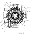
- the cooling medium inlet 74 and thedemediumauslass 78 lead radially away from the housing and are spaced apart by approximately 120 °, such as in Fig. 7 in synopsis with Fig. 8 is shown.
- heat energy is transferred from the gaseous material components via the condenser surface to the cooling medium, which ultimately leads to the condensation of the less volatile substances on the condenser surface.
- the resulting condensate flows down the condenser surface and ultimately onto the condenser bottom in the form of a sink or tub 80, from where it is discharged via corresponding, leading away from the lowest point of the capacitor bottom condensate outlets 82.
- the condensate outlets leading radially away from the housing are spaced 180 degrees, such as in FIG Fig. 7 is shown.
- the material outlet 22 is configured in the form of a subsequent to the treatment chamber and flanged to this discharge device 221.
- the device also has a concentric surrounding the capacitor 34, static cover plate 91, which is cylindrical in the embodiment shown.
- cover plate 91 which is cylindrical in the embodiment shown.
- the rotor 26 has on its inside a bushing 92 with a conveyor coil 94 in the conveying direction down.
- This bushing 92 is disposed at the height of the rotor 26, the height of the in Fig. 8 and 9 shown cover plate 91 corresponds, and formed as a counterpart to the cover plate.
- the gap between the bushing 92 and the cover plate 91 is less than the gap between the rotor 26 and the condenser 34, which is formed further above.
- the bushing 92 rotating with the rotor or the delivery spiral 94 thus becomes a very effective material delivery down and thus ensures a good seal of Kondensatauslasses 82.
Landscapes
- Chemical & Material Sciences (AREA)
- Chemical Kinetics & Catalysis (AREA)
- Organic Chemistry (AREA)
- Vaporization, Distillation, Condensation, Sublimation, And Cold Traps (AREA)
- Processing And Handling Of Plastics And Other Materials For Molding In General (AREA)
Abstract
Description
- Die Erfindung betrifft eine Vorrichtung zur thermischen Behandlung von viskosem Material, insbesondere zur thermischen Auftrennung von in viskosem Material enthaltenen Materialkomponenten, gemäss dem Oberbegriff des Anspruchs 1, und insbesondere einen Kurzwegverdampfer.
- Kurzwegverdampfer werden zur thermischen Behandlung von temperaturempfindlichen Materialien eingesetzt mit dem Ziel, das Material zu konzentrieren oder zu entgasen bzw. die dabei aus dem Material entweichenden gasförmigen Materialkomponenten wahlweise zu destillieren.
- Das Prinzip der Kurzwegverdampfung beruht darauf, dass ein dem Verdampfer zugeführtes Stoffgemisch, welches im Folgenden als "Material" bezeichnet wird, an einer eine Verdampfungsfläche bildenden Behandlungsfläche erhitzt wird und die dabei entweichenden gasförmigen Materialkomponenten an einer der Verdampfungsfläche gegenüberliegenden Kondensatorfläche kondensieren. Dabei wird der Abstand zwischen der Verdampfungsfläche und der Kondensatorfläche sehr gering gewählt, um Druckverluste über den Weg von der Verdampfungsfläche zur Kondensatorfläche zu minimieren. Dies erlaubt es, in Kurzverdampfern mit sehr niedrigen Betriebsdrücken bis 0,001 mbar und entsprechend niedrigen Siedetemperaturen zu arbeiten.
- Beispielhafte Kurzwegverdampfer werden etwa in der
EP 2 039 408 A1 und derEP 2 039 409 A1 beschrieben. - So wird in
EP 2 039 408 A1 konkret ein Kurzwegverdampfer beschrieben, welcher oberhalb des Kondensators eine scheibenförmige, um die Längsachse des Gehäuses drehbare und während des Betriebs rotierende Rotorplatte aufweist, an deren peripherem Randbereich eine Aufhängung angeordnet ist mit daran umlaufend angeordneten Verteilungsmitteln zur Verteilung des zugeführten Materials auf der Verdampfungsfläche. Konkret können diese Verteilungsmittel gemäss derEP 2 039 408 in Form von Wischblättern vorliegen, welche in Umfangsrichtung in regelmässigen Abständen und in axialer Richtung derart versetzt zueinander angeordnet sind, dass sie auf einer um die Längsachse herum verlaufenden Spirale liegen. - Die in
EP 2 039 408 A1 undEP 2 039 409 A1 beschriebenen Kurzwegverdampfer sind auf relative tiefviskose Stoffgemische ausgelegt, welche auf der Verdampfungsfläche aufgrund der Gravitation nach unten fliessen und auf diesem Weg permanent auf der Verdampfungsfläche ausgestrichen werden, wodurch die Verweilzeit erhöht wird. - Weiter wird in
DE 1 444 326 A eine Vorrichtung zum Verdampfen, Trennen oder Destillieren von Flüssigkeiten mit einer beheizten, zu einer vertikalen Achse rotationssymmetrischen Trägerfläche beschrieben, auf welcher die Flüssigkeit in dünner Schicht nach unten fliessen kann. Dabei wird zum Ausbreiten der Flüssigkeitsschicht auf der Trägerfläche ein Streichorgan vorgesehen, welches schraubenlinienförmig verläuft, um die Achse drehbar ist und während der Rotationsbewegung in axiale Schwingungen versetzt wird, die in der Flüssigkeitsschicht Interferenzwellen erzeugen. - Allerdings sind die in
EP 2 039 408 A1 ,EP 2 039 409 A1 undDE 1 444 326 beschriebenen Kurzwegdampfer für Materialien bzw. Stoffgemische mit hoher Viskosität nicht oder nur beschränkt geeignet. So liegt die Viskositätsobergrenze für konventionelle Kurzwegverdampfer üblicherweise bei ca. 25 Pas, da gewährleistet sein muss, dass das zu behandelnde Gut unter Einwirkung der Schwerkraft nach unten fliessen kann. - Mit der thermischen Behandlung hochviskoser Produkte unter gleichzeitiger Gewährleistung einer gleichmässigen Verteilung des zu behandelnden Guts auf der Behandlungsfläche befasst sich die
DE 195 35 817 A1 . In diesem Zusammenhang wird eine Vorrichtung beschrieben, welche ein Kernrohr aufweist, an dem parallel zur Rotorachse angeordnete, winkelförmige Stegbleche angeschweisst sind, an deren Aussenseite Blattelemente schraubenförmig angeordnet sind. Obschon damit im Vergleich zu den oben beschriebenen Verteilelementen bzw. Streichorganen die Verweilzeit von viskosem Material verkürzt werden kann, ist die Vorrichtung für die Behandlung von sehr hochviskosen Materialien, insbesondere Materialien mit einer Viskosität weit höher als 25 Pas, nur beschränkt geeignet. - Aufgabe der Erfindung ist es somit, eine Vorrichtung zur thermischen Behandlung von Material, insbesondere zur thermischen Auftrennung von im Material enthaltenen Materialkomponenten, zur Verfügung zu stellen, welche es erlaubt, für temperaturempfindliche Materialien auch dann eine gute Auftrennung von im Material enthaltenen Materialkomponenten zu erzielen, wenn das Material eine sehr hohe Viskosität aufweist, insbesondere eine Viskosität höher als 100 Pas, im Speziellen höher als 1'000 Pas.
- Die erfindungsgemässe Aufgabe wird gelöst durch die Vorrichtung nach Anspruch 1. Bevorzugte Ausführungsformen sind in den abhängigen Ansprüchen wiedergegeben.
- Wie eingangs erwähnt ist die Vorrichtung auf die thermische Behandlung von viskosem Material, insbesondere auf die thermische Auftrennung von in viskosem Material enthaltenen Materialkomponenten ausgerichtet. Sie betrifft insbesondere einen Kurzwegverdampfer.
- Die Vorrichtung umfasst ein Gehäuse mit einem beheizbaren Gehäusemantel, welcher eine Behandlungskammer umschliesst und eine rotationssymmetrische, sich in Achsrichtung erstreckende Behandlungsfläche bildet. Die Vorrichtung ist typischerweise vertikal ausgerichtet; die Achsrichtung, auf die im Rahmen der vorliegenden Erfindung Bezug genommen wird, entspricht somit in der Regel der Vertikalen.
- In einem Einlassbereich des Gehäuses ist ein Materialeinlass zum Einführen des zu behandelnden Materials in die Behandlungskammer angeordnet, während in einem Auslassbereich des Gehäuses ein Materialauslass zum Austragen des Materials aus der Behandlungskammer angeordnet ist. Dieser Materialauslass ist bei der vertikal ausgerichteten Vorrichtung somit in einem unteren Bereich des Gehäuses angeordnet, während der Materialeinlass weiter oben angeordnet ist.
- Die Vorrichtung weist zudem einen in der Behandlungskammer angeordneten und sich koaxial erstreckenden, antreibbaren Rotor zur Erzeugung eines Materialfilms auf der Behandlungsfläche auf, wobei der Rotor eine Hohlwelle umfasst, über deren Umfang verteilt Streichelemente angeordnet sind, deren radial äusserstes, d.h. peripheres, Ende von der Behandlungsfläche beabstandet ist. Typischerweise liegt der Abstand des peripheren Endes der Streichelemente und der Behandlungsfläche im Bereich von ca. 1 bis 5 mm, wobei er in manchen Fällen, insbesondere bei sehr grossvolumigen Vorrichtungen, bis zu 8 mm betragen kann.
- Die Hohlwelle umschliesst einen Kondensationsraum, in welchem ein in der Regel statischer Kondensator angeordnet ist, und weist Durchlassöffnungen auf, durch welche bei der thermischen Behandlung aus dem Material entweichende gasförmige Materialkomponenten in den Kondensationsraum gelangen können. Die Hohlwelle ist in der Regel zylinderförmig, insbesondere kreiszylinderförmig, ausgestaltet, wobei die Durchlassöffnungen in der Zylindermantelfläche angeordnet sind.
- Die Streichelemente sind mindestens teilweise als Förderelemente ausgestaltet, welche dem Material eine Förderkomponente in Richtung vom Materialeinlass zum Materialauslass hin, d.h. in der Regel nach unten, verleihen.
- Gemäss der Erfindung sind mindestens in einem Längsabschnitt des Rotors, insbesondere in einem zentralen Längsabschnitt, die Streichelemente teilweise als Förderelemente ausgestaltet und teilweise als von der Hohlwelle abstehende Verteilelemente, welche Zähne umfassen, deren Scherkante bezogen zur Achsrichtung einen Winkel kleiner als 45° einschliesst.
- Erfindungsgemäss liegen somit Streichelemente vor, denen primär eine Förderfunktion zukommt und die somit ein Förderelement bilden, und Streichelemente, die in erster Linie eine Verteilfunktion übernehmen und somit Verteilelemente bilden.
- Aufgrund des Vorliegens der Förderelemente wird einerseits gewährleistet, dass auch sehr hochviskose Materialien mit einer ausreichend hohen Förderrate durch die Behandlungskammer hindurch gefördert werden und somit die Verweilzeit bzw. die Behandlungsdauer, während welcher das Material erhöhten Temperaturen und hohen Scherraten ausgesetzt wird, ausreichend tief gehalten werden kann. Andererseits wird durch das Vorliegen der Verteilelemente eine sehr gute Verteilung und eine optimale Oberflächenerneuerung auf der Behandlungsfläche auch dann gewährleistet, wenn das Material eine sehr hohe Viskosität aufweist.
- Letztendlich kann somit erfindungsgemäss eine optimale Behandlung, insbesondere eine hohe Entgasungsrate, von sehr hochviskosem Material erzielt werden und gleichzeitig der Energieeintrag in das Material auf ein Mass beschränkt werden, bei dem das Material keinen Schaden nimmt und insbesondere kein thermisch bedingter Abbau erfolgt.
- Die erfindungsgemässe Vorrichtung erlaubt es somit, Materialien mit einer Viskosität von bis zu 15'000 Pas optimal zu behandeln, insbesondere zu entgasen und in manchen Fällen auch zu reagieren, sei es in Kombination mit der Entgasung oder unabhängig davon. Im Speziellen eignet sich die erfindungsgemässe Vorrichtung für die Behandlung sehr hochviskoser Polymere, bei welchen nach der Polymerisationsreaktion noch im Polymerisat enthaltene Lösemittel und/oder überschüssige oder während einer Reaktion unerwünscht gebildete Monomere oder Oligomere mit relativ hohem Siedepunkt abzutrennen sind.
- In besonderem Masse vorteilhaft ist die erfindungsgemässe Vorrichtung für die Behandlung von Polymeren auf der Basis von nachwachsenden Rohstoffen, da diese im Allgemeinen relativ temperaturempfindlich sind. Die erfindungsgemässe Vorrichtung ist insbesondere auch für die Behandlung von Polymeren und hochviskosen Materialien vorteilhaft, die für Anwendungen im Bereich der Medizin, Kosmetik und Lebensmitteltechnologie einen besonders hohen Grad an Entgasung aufweisen sollen. Wie erwähnt ist die Vorrichtung gerade zur Behandlung von relativ temperaturempfindlichen Materialien besonders gut geeignet, weil die Wärmeenergie, der das Material ausgesetzt wird, durch die relativ tief wählbare Temperatur und Verweilzeit auf der Behandlungsfläche, optimal eingestellt werden kann.
- Typischerweise liegt die Viskosität des mit der erfindungsgemässen Vorrichtung zu behandelnden Materials im Bereich von 100 bis 15'000 Pas, insbesondere von 1'000 Pas bis 10'000 Pas und im Speziellen von 1'500 Pas bis 6'000 Pas. Die Viskositätswerte beziehen sich dabei auf die Betriebstemperatur und ein Schergefälle von D=10 sec-1.
- Was die Betriebstemperatur der erfindungsgemässen Vorrichtung betrifft, so liegt diese im Allgemeinen in einem Bereich von 40 bis 400°C, insbesondere von 150 bis 350°C und im Speziellen von 20 bis 300°C.
- Das anspruchsgemässe Merkmale, dass die Streichelemente "mindestens in einem Längsabschnitt des Rotors" teilweise als Förderelemente und teilweise als Verteilelemente ausgebildet sind, bedeutet, dass von der Erfindung Ausführungsformen umfasst sind, in welcher diese Ausbildung der Streichelemente über die gesamte Länge des Rotors verwirklicht ist als auch Ausführungsformen, in welchen dies nur über einen Teil der Rotorlänge verwirklicht ist, insbesondere nur in einem zentralen Längsabschnitt.
- Wie erwähnt umfassen die Verteilelemente Zähne, die von der Hohlwelle abstehen. Denkbar ist dabei, dass die Zähne in mindestens annähernd radialer Richtung von der Hohlwelle abragen oder aber in einem Winkel zur radialen Richtung. In der Regel sind die Zähne jeweils an einem von mehreren auf der Hohlwelle angeordneten, axial verlaufenden Flanschen fixiert.
- Gemäss einer bevorzugten Ausführungsform schliesst die Scherkante mindestens eines Teils der Zähne bezogen zur Achsrichtung einen Winkel im Bereich von 0 bis 40° ein.
- Abhängig von der jeweiligen Anwendung kann insbesondere bevorzugt sein, dass besagter Winkel im Bereich von 10 bis 30° liegt und im Speziellen bei ca. 20°. Gemäss dieser Ausführungsform erteilen somit auch die Verteilelemente dem zum behandelnden Material eine Förderkomponente in Richtung zum Materialauslass hin, wobei diese Förderkomponente geringer ist als diejenige der Förderelemente. Denkbar ist für diese Ausführungsform etwa, dass die Zähne ein proximales Teilstück aufweisen, welches in einer parallel zur Achsrichtung verlaufenden Ebene liegt und über welches die Zähne angeflanscht werden, und ein distales Teilstück, das in einer schräg zur Achsrichtung verlaufenden Ebene liegt und dessen radial äusseres Ende die Scherkante bildet.
- Je nach Anwendung kann alternativ zu dieser Ausführungsform bevorzugt sein, dass die Scherkante mindestens eines Teils der Verteilelemente einen geringeren als den oben genannten Winkel einschliesst und insbesondere mindestens annähernd parallel zur Achsrichtung verläuft, d.h. bezogen zu dieser einen Winkel von ca. 0° einschliesst. Im letztgenannten Fall sind die Verteilelemente vollkommen förderneutral und haben ausschliesslich verteilende Funktion. Welche konkrete Konfiguration der Verteilelemente gewählt wird, hängt letztendlich vom zu behandelnden Material ab und kann innerhalb der erfindungsgemässen Definition variieren.
- Was die Förderelemente betrifft, so umfassen diese mindestens eine Förderrippe, deren radiale Aussenkante bezogen zur Achsrichtung in der Regel einen Winkel grösser als 45° einschliesst. Somit ist auch bei sehr hochviskosem Material die durch das Förderelement verliehene Förderkomponente ausreichend hoch, um eine gewünschte Förderrate durch die Behandlungskammer hindurch zu erhalten.
- Vorzugsweise schliesst die radiale Aussenkante der Förderrippe bezogen zur Achsrichtung einen Winkel von höchstens 65° ein. Im Speziellen liegt der Winkel in einem Bereich von 50° bis 60°.
- Nebst dem, dass die Förderwirkung eines Förderelementes durch den Anstellwinkel der radialen Aussenkante einer Förderrippe bestimmt wird, kann die Förderwirkung des Förderelementes zusätzlich über die Anzahl der Förderrippen bzw. den Abstand zwischen den in Achsrichtung aufeinanderfolgenden Förderrippen eingestellt werden.
- Gemäss einer besonders bevorzugten Ausführungsform umfassen die Förderelemente jeweils ein wenigstens annähernd parallel zur Achsrichtung angeordnetes, winkelförmiges Stegblech, an dessen Aussenseite mindestens eine helikal verlaufende Förderrippe angeordnet ist. Durch die Winkelform wird das Stegblech somit in eine erste und zweite Stegblechfläche unterteilt, welche in zueinander schräg verlaufenden Ebenen liegen.
- Nebst der Aussenkante der Förderrippe ergibt sich bei dieser Ausführungsform durch die Winkelform des Stegblechs eine in der Regel axial verlaufende Scherkante, welche gegenüber der radialen Aussenkante der Förderrippe zurückversetzt ist und somit im Vergleich zu dieser von der Behandlungsfläche in einem grösseren Abstand angeordnet ist. Somit trägt gemäss dieser Ausführungsform auch das Förderelement zu einer optimalen Verteilung des Materials auf der Behandlungsfläche bei.
- Gemäss einer weiteren bevorzugten Ausführungsform sind in Umfangsrichtung des Rotors die Verteilelemente mit den Förderelementen alternierend angeordnet, da dadurch eine sehr homogene Verteilung des Materials auf der Behandlungsfläche gewährleistet werden kann.
- Des Weiteren kann bevorzugt sein, im Bereich des Materialeinlasses die Streichelemente des Rotors lediglich als Förderelemente auszubilden, um insbesondere in diesem Bereich eine hohe Förderrate zu erzielen und damit einem Aufstauen von Material entgegenzuwirken.
- Typischerweise liegt im Betrieb der Vorrichtung in der Behandlungskammer ein Druck im Bereich von 0.1 bis 0.5 Pa vor, um auch bei moderaten Temperaturen eine möglichst hohe Entgasungsrate zu erzielen.
- Bei einem derart tiefen Betriebsdruck bzw. einem derart hohen Vakuum wird vorzugsweise eine Vorentgasungsstufe vorgesehen, die einen Grossteil der flüchtigen Bestandteile des zu behandelnden Materials abtrennt, bevor das Material in die Behandlungskammer eingeführt wird. Damit wird der Gasvolumenstrom in einem handhabbaren Mass gehalten. Vorzugsweise befindet sich das zu behandelnde Material unmittelbar vor der Einführung im Gleichgewicht mit der Gasphase.
- Selbstverständlich kann je nach Anwendungsfall der Betriebsdruck der Vorrichtung auch höher sein, wenn sich dadurch eine gute Behandlung, insbesondere eine ausreichende Entgasung, gewährleisten lässt.
- Aufgrund dessen, dass das Material bei der Einführung in die Behandlungskammer einer starken Druckverminderung ausgesetzt wird, können nichtsdestotrotz gasförmige Komponenten (im Zuge einer sogenannten "Flash"-Verdampfung) instantan aus dem Material entweichen, was wiederum zu einem Mitriss von Material führen kann. Um zu vermeiden, dass mitgerissenes Material auf die Hohlwelle und letztendlich in den Kondensationsraum gelangen und das Kondensat verunreinigen kann, weist die Vorrichtung gemäss einer bevorzugten Ausführungsform im Bereich des Materialeinlasses einen die Hohlwelle vollständig umgebenden Spritzschutzmantel auf.
- Dabei wird gemäss einer möglichst einfachen und daher bevorzugten Ausführungsform der Spritzschutzmantel von den Förderelementen und von jeweils zwei in Umfangsrichtung aufeinanderfolgenden, Förderelemente verbindenden Blechen gebildet. Für die oben genannte Ausführungsform, in welcher die Förderelemente jeweils ein winkelförmiges Stegblech mit mindestens einer an der Aussenseite helikal verlaufenden Förderrippe umfassen, kann somit eine erste Dachseite eines ersten Förderelements mit der zweiten Dachseite eines in Rotationsrichtung dem ersten Förderelement vorauslaufenden zweiten Förderelements verbunden werden, wie im Zusammenhang mit den Figuren weiter ausgeführt wird.
- Um auch im Bereich des Materialauslasses ein Aufstauen von Material zu verhindern, sind gemäss einer weiteren bevorzugten Ausführungsform auch in diesem Bereich die Streichelemente des Rotors lediglich als Förderelemente ausgebildet.
- In der Regel liegt die Anzahl an in Umfangsrichtung verteilten Streichelementen zwischen 4 und 80, bevorzugt zwischen 6 und 48, und beträgt am meisten bevorzugt zwischen 8 und 32. Dadurch kann eine sehr gute Förderung und Verteilung des Materials während seiner Behandlung auf der Behandlungsfläche erzielt werden. Die optimale Anzahl an Streichelementen hängt dabei von der jeweiligen Anwendung und von der Grösse bzw. dem Durchmesser des Rotors ab.
- Wie ebenfalls im Rahmen der Figuren ausgeführt wird, weist gemäss einer besonders bevorzugten Ausführungsform der Rotor zwischen dem Einlassbereich und dem Auslassbereich, in welchen sämtliche Streichelemente als Förderelement ausgestaltet sind, einen Zentralbereich auf, über den sich Förderelemente in axialer Fortsetzung eines Teils der Förderelemente des Einlassbereichs hin erstrecken. Diese alternieren im Zentralbereich jeweils mit einem Verteilelement, welches jeweils ebenfalls in axialer Fortsetzung zu einem Förderelement des Einlassbereichs angeordnet ist.
- Wie erwähnt ist der Kondensator erfindungsgemäss in einem Kondensationsraum angeordnet, der von der Hohlwelle umschlossen wird.
- Gemäss einer besonders bevorzugten Ausführungsform umfasst der Kondensator ein Innenrohr und ein das Innenrohr konzentrisch umgebendes Aussenrohr. Sowohl das Aussenrohr als auch das Innenrohr weisen jeweils eine Aussenwand und eine Innenwand auf, die mindestens bereichsweise voneinander beabstandet sind und derart im Innenrohr einen Innenrohr-Kühlmediumzirkulationskanal und im Aussenrohr einen Aussenrohr-Kühlmediumzirkulationskanal bilden. Dabei sind der Innenrohr-Kühlmediumzirkulationskanal und der Aussenrohr-Kühlmediumzirkulationskanal miteinander strömungsverbunden. Dabei ist der Kondensator in der Regel derart ausgestaltet, dass in einen der beiden Kühlmediumzirkulationskanäle, also z.B. in den Aussenrohr-Kühlmediumzirkulationskanal, eine Kühlmediumzuleitung mündet und vom jeweils anderen Kühlmediumzirkulationskanal, also im genannten Beispiel vom Innenrohr-Kühlmediumzirkulationskanal, ein Kühlmediumauslass wegführt. Typischerweise sind die Kühlmediumzuleitung und der Kühlmediumauslass in einem unteren Bereich des Kondensators angeordnet und die Verbindung zwischen den Kühlmediumzirkulationskanälen in einem oberen Bereich. Somit strömt das Kühlmedium im Betrieb von einem unteren Bereich des einen Aussen/Innenrohrs nach oben, tritt in einem oberen Bereich in das jeweils andere Rohr über und strömt von dort im Innen- bzw. Aussenrohrs nach unten.
- Denkbar ist weiter, dass das Innenrohr und das Aussenrohr jeweils aus einer Platte gebildet werden, in welcher die Innenwand mit der Aussenwand punktuell miteinander verschweisst sind, wobei das sich zwischen der Innenwand und der Aussenwand ergebende Hohlkissen als Kühlmediumzirkulationskanal dient. Für die Schweissverbindung können dabei Schweisskreise vorgesehen sein, während am jeweils oberen und unteren Ende der Platte das Hohlkissen in der Regel über umlaufende Nähte abgeschlossen ist. Dies erlaubt eine sehr leichte und kompakte, aber nichtsdestotrotz sehr stabile Ausgestaltung des Kondensators.
- Weiter sind im Aussenrohr in der Regel Fenster angeordnet, welche gewährleisten sollen, dass die gasförmigen Komponenten zur Kondensation auch an das Innenrohr gelangen können. Die Fenster sind dabei vorzugsweise in Längs- und in Umfangsrichtung gleichmässig angeordnet.
- Im Vergleich zu von der Erfindung ebenfalls mitumfassten Vorrichtungen, in welchen der Kondensator als Rohrbündelkondensator ausgebildet ist, ergeben sich für die oben genannte besonders bevorzugte Ausgestaltung des Kondensators verbesserte statische Eigenschaften, was gerade im Hinblick auf ein gegenüber herkömmlichen Vorrichtungen erhöhtes L/D-Verhältnis der auf die Behandlung sehr hochviskoser Materialien ausgerichteten erfindungsgemässen Vorrichtung besonders vorteilhaft ist.
- Ein Rohrbündelkondensator kann etwa bei sehr grossen Vorrichtungen bevorzugt sein, wobei die Verwendung eines Rohrbündelkondensators auch für kleinere Vorrichtungen nicht ausgeschlossen ist. Vorzugsweise sind die Rohre des Rohrbündelkondensators in zwei konzentrischen Reihen blickdicht versetzt zueinander angeordnet.
- Gemäss einer weiteren bevorzugten Ausführungsform der erfindungsgemässen Vorrichtung weist das Gehäuse einen Vakuumanschluss auf, welcher derart ausgestaltet ist, ein Vakuum direkt am Kondensationsraum, d.h. am Innenraum der Hohlwelle anzulegen. Dabei ist besonders bevorzugt, dass der Vakuumanschluss in einen Oberteil des Gehäuses mündet, welcher mit dem Kondensationsraum strömungsverbunden ist und gegenüber der Behandlungskammer abgedichtet ist, wobei für die Abdichtung insbesondere eine rotierende Labyrinthdichtung vorgesehen werden kann.
- Insbesondere im Zusammenhang mit der oben genannten Ausführungsform, gemäss welcher im Bereich des Materialeinlasses ein die Hohlwelle vollständig umgebender Spritzschutzmantel vorliegt, kann somit gewährleistet werden, dass in diesem Bereich das Material im Gleichstrom geführt wird und dass lediglich gasförmige Komponenten abgezogen werden, die den Kondensationsraum passiert haben und somit unter den gegebenen Bedingungen nicht kondensierbar sind (d.h. leichtflüchtige Komponenten darstellen). Dies resultiert letztendlich in einer hohen Kondensationsrate der niedriger siedenden Komponenten des behandelten Materials.
- Der Rotor ist in der Regel fliegend gelagert. Gemäss einer bevorzugten Ausführungsform weist er in seinem materialauslassseitigen, d.h. unteren Endbereich mindestens zwei achsensymmetrisch angeordnete Lagerschuhe auf und wird radial von einem Lagerring des Gehäuses geführt, welcher zusammen mit den Lagerschuhen ein materialgeschmiertes Lager bildet.
- Die Lagerschuhe sind dabei vorzugsweise in einer Art und Weise ausgestaltet, während der Rotation des Rotors Material in den radialen Spalt zwischen Lagerring und Lagerschuh zu drücken. Weiter ist bevorzugt, dass zwischen den Lagerschuhen zusätzlich Förderelemente angeordnet sind, insbesondere Förderelemente gemäss obiger Beschreibung umfassend ein winkelförmiges Stegblech mit mindestens eine an dessen Aussenseite helikal verlaufende Förderrippe. Dadurch wird gewährleistet, dass der Materialtransport durch die radiale Rotorführung bzw. das Lager mindestens annähernd beibehalten werden kann.
- Durch die radiale Führung im unteren Bereich des Rotors werden Vorrichtungen mit einem gegenüber herkömmlichen Kurzwegverdampfern sehr hohen L/D-Verhältnis ermöglicht, was gerade im Hinblick darauf, dass die erfindungsgemässe Vorrichtung auf die Behandlung sehr hochviskoser Materialien ausgerichtet ist, besonders vorteilhaft ist.
- In der Regel liegt der Materialeinlass der erfindungsgemässen Vorrichtung in Form eines tangential zum Gehäuse ausgerichteten Anschlusses vor; dies im Unterschied zu vorbekannten Kurzwegverdampfern, wie etwa demjenigen gemäss
EP 2 039 409 , in welchem die Materialzuführung von oben, also durch den die Behandlungskammer oben abschliessenden Deckel erfolgt. - Was den Materialauslass betrifft, so ist dieser vorzugsweise in Form einer sich in Achsrichtung an die Behandlungskammer anschliessenden, also zentral angeordneten, Austragsvorrichtung ausgebildet. Diese kann etwa in Form eines Trichters mit einem konischen Zulaufbehälter und einer standgeregelten Pumpe vorliegen. Damit unterscheidet sich die erfindungsgemässe Vorrichtung weiter von vorbekannten Kurzwegverdampfern, wie etwa dem in
EP 2 039 409 gezeigten, in welchen das Material seitlich, in der Regel über eine Tasse, aus der Behandlungskammer ausgeführt wird. - Gemäss einer besonderen Ausführungsform kann eine von unten angebaute und angetriebene Austragshilfe, insbesondere eine Förderschnecke, vorgesehen sein, welche das Produkt einer seitlich angeordneten Pumpe zuführt. Gemäss einer weiteren besonderen Ausführungsform ist denkbar, die Austragshilfe direkt an das beschriebene Lager anzuschliessen und mit der gleichen Drehzahl wie der Rotor das behandelte Material einer unten angeordneten Austragspumpe zuzuführen.
- Damit wird auch bei einer sehr hohen Viskosität des fertig behandelten, auszutragenden Materials eine relativ hohe Austragsförderrate gewährleistet und ein Aufstauen vor dem Materialauslass minimiert oder verhindert.
- Um nichtsdestotrotz sicherzustellen, dass sich allfällig aufstauendes Material nicht an den Kondensator gelangen und den Kondensatauslass verstopfen kann, weist die Vorrichtung gemäss einer weiteren bevorzugten Ausführungsform ein den Kondensator konzentrisch umgebendes statisches Abdeckblech auf. So wird Material, welches bei einem unzureichenden Materialaustrag nach oben gedrückt wird, durch das Abdeckblech vom Kondensator ferngehalten. Hierfür kann bevorzugt sein, dass sich das Abdeckblech nach oben hin konisch verjüngt. Es ist aber auch ein zylindrisches Abdeckblech denkbar.
- Insbesondere hinsichtlich der Ausführungsform, in welcher das Abdeckblech zylindrisch ausgebildet ist, ist weiter bevorzugt, dass auf der Höhe des Abdeckblechs der Rotor auf seiner Innenseite eine als Gegenstück zum Abdeckblech ausgebildete Buchse mit einer darauf innenseitig aufgebrachten Förderwendel aufweist. Diese Buchse rotiert somit mit dem Rotor. Die Förderwendel weist eine Förderrichtung nach unten, d.h. zum Materialauslass hin, auf. Der Spalt zwischen der Buchse und dem Abdeckblech ist dabei geringer als der weiter oben ausgebildete Spalt zwischen dem Rotor und dem Kondensator, womit die Förderwendel in einem relativ kurzen Abstand zum Abdeckblech läuft und wodurch letztendlich eine sehr effektive Materialförderung nach unten und eine gute Abdichtung des Kondensatauslasses gewährleistet werden kann.
- Nebst der oben beschriebenen Vorrichtung betrifft die vorliegende Erfindung gemäss einem weiteren Aspekt eine Vorrichtung zur thermischen Behandlung von viskosem Material, insbesondere zur thermischen Auftrennung von in viskosem Material enthaltenen Materialkomponenten, umfassend ein Gehäuse mit einem beheizbaren Gehäusemantel, welcher eine Behandlungskammer umschliesst und eine rotationssymmetrische, sich in Achsrichtung erstreckende Behandlungsfläche bildet, einen in einem Einlassbereich des Gehäuses angeordneten Materialeinlass zum Einführen des zu behandelnden Materials in die Behandlungskammer, einen in einem Auslassbereich des Gehäuses angeordneten Materialauslass zum Austragen des Materials aus der Behandlungskammer, und einen in der Behandlungskammer angeordneten und sich koaxial erstreckenden, antreibbaren Rotor zur Erzeugung eines Materialfilms auf der Behandlungsfläche, wobei der Rotor eine Hohlwelle umfasst, über deren Umfang verteilt Streichelemente angeordnet sind, deren radial äusserstes Ende von der Behandlungsfläche beabstandet ist, wobei die Hohlwelle einen Kondensationsraum umschliesst, in welchem ein Kondensator angeordnet ist, und Durchlassöffnungen aufweist, durch welche bei der thermischen Behandlung aus dem Material entweichende gasförmige Materialkomponenten in den Kondensationsraum gelangen können, dadurch gekennzeichnet, dass der Kondensator ein Innenrohr und ein das Innenrohr konzentrisch umgebendes Aussenrohr umfasst, welche jeweils eine Aussenwand und eine Innenwand aufweisen, die mindestens bereichsweise voneinander beabstandet sind und derart im Innenrohr einen Innenrohr-Kühlmediumzirkulationskanal und im Aussenrohr einen Aussenrohr-Kühlmediumzirkulationskanal bilden, und der Innenrohr-Kühlmediumzirkulationskanal und der Aussenrohr-Kühlmediumzirkulationskanal miteinander strömungsverbunden sind.
- Dieser Aspekt der Erfindung erlaubt es, eine Vorrichtung zur Verfügung zu stellen, welche im Vergleich zu Vorrichtungen, in welchen der Kondensator als Rohrbündelkondensator ausgebildet ist, verbesserte statische Eigenschaften aufweist. Insbesondere werden Vorrichtungen mit einem gegenüber herkömmlichen Vorrichtungen erhöhten L/D-Verhältnis ermöglicht, was gerade hinsichtlich der Anwendung der Vorrichtung zur Behandlung sehr hochviskoser Materialien eine optimale Behandlung des Materials ermöglicht.
- Gemäss einem weiteren Aspekt betrifft die vorliegende Erfindung im Übrigen eine Vorrichtung zur thermischen Behandlung von viskosem Material, insbesondere zur thermischen Auftrennung von in viskosem Material enthaltenen Materialkomponenten, umfassend ein Gehäuse mit einem beheizbaren Gehäusemantel, welcher eine Behandlungskammer umschliesst und eine rotationssymmetrische, sich in Achsrichtung erstreckende Behandlungsfläche bildet, einen in einem Einlassbereich des Gehäuses angeordneten Materialeinlass zum Einführen des zu behandelnden Materials in die Behandlungskammer, einen in einem Auslassbereich des Gehäuses angeordneten Materialauslass zum Austragen des Materials aus der Behandlungskammer, und einen in der Behandlungskammer angeordneten und sich koaxial erstreckenden, antreibbaren Rotor zur Erzeugung eines Materialfilms auf der Behandlungsfläche, wobei der Rotor eine Hohlwelle umfasst, über deren Umfang verteilt Streichelemente angeordnet sind, deren radial äusserstes Ende von der Behandlungsfläche beabstandet ist, wobei die Hohlwelle einen Kondensationsraum umschliesst, in welchem ein Kondensator angeordnet ist, und Durchlassöffnungen aufweist, durch welche bei der thermischen Behandlung aus dem Material entweichende gasförmige Materialkomponenten in den Kondensationsraum gelangen können, dadurch gekennzeichnet, dass die Vorrichtung im Bereich des Materialeinlasses einen die Hohlwelle vollständig umgebenden Spritzschutzmantel aufweist.
- Wie oben dargelegt wird dadurch vermieden, dass Material, welches bei der Einführung in die Behandlungskammer durch eine Flash-Verdampfung mitgerissen wird, auf die Hohlwelle und letztendlich in den Kondensationsraum gelangen und das Kondensat verunreinigen kann.
- Gemäss einem weiteren Aspekt betrifft die Erfindung eine Vorrichtung zur thermischen Behandlung von viskosem Material, insbesondere zur thermischen Auftrennung von in viskosem Material enthaltenen Materialkomponenten, umfassend ein Gehäuse mit einem beheizbaren Gehäusemantel, welcher eine Behandlungskammer umschliesst und eine rotationssymmetrische, sich in Achsrichtung erstreckende Behandlungsfläche bildet, einen in einem Einlassbereich des Gehäuses angeordneten Materialeinlass zum Einführen des zu behandelnden Materials in die Behandlungskammer, einen in einem Auslassbereich des Gehäuses angeordneten Materialauslass zum Austragen des Materials aus der Behandlungskammer, und einen in der Behandlungskammer angeordneten und sich koaxial erstreckenden, antreibbaren Rotor zur Erzeugung eines Materialfilms auf der Behandlungsfläche, wobei der Rotor eine Hohlwelle umfasst, über deren Umfang verteilt Streichelemente angeordnet sind, deren radial äusserstes Ende von der Behandlungsfläche beabstandet ist, wobei die Hohlwelle einen Kondensationsraum umschliesst, in welchem ein Kondensator angeordnet ist, und Durchlassöffnungen aufweist, durch welche bei der thermischen Behandlung aus dem Material entweichende gasförmige Materialkomponenten in den Kondensationsraum gelangen können, und die Streichelemente mindestens teilweise als Förderelemente ausgestaltet sind, welche dem Material eine Förderkomponente in Richtung vom Materialeinlass zum Materialauslass hin verleihen, dadurch gekennzeichnet, dass das Gehäuse einen Vakuumanschluss aufweist, welcher derart ausgestaltet ist, Vakuum direkt am Kondensationsraum, d.h. am Innenraum der Hohlwelle anzulegen, insbesondere dass der Vakuumanschluss in einen Oberteil des Gehäuses mündet, welcher mit dem Kondensationsraum strömungsverbunden ist und gegenüber der Behandlungskammer abgedichtet ist.
- Somit kann eine Vorrichtung zur Verfügung gestellt werden, mit welcher lediglich gasförmige Komponenten abgezogen werden, die den Kondensationsraum passiert haben, was letztendlich in einer hohen Kondensationsrate der niedriger siedenden Komponenten des behandelten Materials resultiert.
- Für alle der beschriebenen weiteren Aspekte der Erfindung gelten die für den ersten Aspekt als bevorzugt genannten Merkmale gleichermassen als bevorzugt.
- Die Erfindung wird anhand der anliegenden Figuren weiter veranschaulicht.
- Es zeigt:
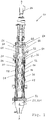
- Fig. 1
- eine Vorrichtung gemäss der vorliegenden Erfindung, wobei der Anschaulichkeit halber der Gehäusemantel und die Hohlwelle insoweit aus der Darstellung entfernt wurden, um den Blick auf den Kondensator freizugeben;
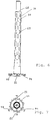
- Fig. 2
- eine Ansicht des Rotors der Vorrichtung gemäss
Fig. 1 ; - Fig. 3
- eine perspektivische Ansicht einer oberhalb des Materialeinlasses quer zur Achsrichtung geschnittenen Vorrichtung gemäss der vorliegenden Erfindung;
- Fig. 4
- einen Querschnitt durch die Vorrichtung gemäss
Fig. 3 auf der Höhe des Materialeinlasses; - Fig. 5
- eine Detailansicht der in
Fig. 4 gezeigten Förderelemente; - Fig. 6
- eine Ansicht des Kondensators der Vorrichtung gemäss
Fig. 1 ; - Fig. 7
- den in
Fig. 6 gezeigten Kondensator im Querschnitt; - Fig. 8
- den in
Fig. 6 gezeigten Kondensator im Längsschnitt entlang den inFig. 7 gezeigten Schnittebenen; - Fig. 9
- einen vergrösserten Längsschnitt des untersten Teils des in
Fig. 6 gezeigten Kondensators; und - Fig. 10
- eine perspektivische Ansicht des materialauslassseitigen Endbereichs des Rotors.
- Wie in
Fig. 1 gezeigt, umfasst die erfindungsgemässe Vorrichtung 10 ein vertikal ausgerichtetes Gehäuse 12 mit einem beheizbaren Gehäusemantel 14, welcher eine Behandlungskammer 16 umschliesst und auf seiner Innenseite eine rotationssymmetrische, sich in Achsrichtung A erstreckende Behandlungsfläche 18 bildet. - Die Vorrichtung umfasst zudem einen durch den Gehäusemantel 14 hindurchführenden Materialeinlass 20 zum Einführen des zu behandelnden Materials in die Behandlungskammer 16 sowie einen Materialauslass 22. Der tangential zum Gehäusemantel ausgerichtete Materialeinlass 20 ist im Übrigen z.B. in
Fig. 4 gezeigt. - In der Behandlungskammer 16 ist ein sich koaxial erstreckender, über eine Antriebseinheit 24 antreibbarer Rotor 26 angeordnet. Dieser umfasst eine Hohlwelle 28 und über deren Umfang verteilt angeordnete, von der Hohlwelle 28 abstehende Streichelemente 30. Dabei ist das radial äusserste Ende der Streichelemente 30 von der Behandlungsfläche 18 beabstandet, um im Betrieb, d.h. während der Rotation des Rotors 26, das Material zu einem dünnen Materialfilm auf der Behandlungsfläche 18 auszustreichen.
- Die Hohlwelle 28 umschliesst einen Kondensationsraum 32, in welchem ein statischer Kondensator 34 angeordnet ist, und weist Durchlassöffnungen 36 auf, durch welche bei der thermischen Behandlung aus dem Material entweichende gasförmige Materialkomponenten in den Kondensationsraum 32 gelangen, um dort am Kondensator 34 kondensieren zu können.
- In dem in den
Fig. 2 bis 4 gezeigten Rotor 26 sind die Streichelemente in insgesamt 16 parallel zur Achsrichtung verlaufenden Reihen über den Umfang der Hohlwelle 28 verteilt angeordnet. - In einem Einlassbereich 21, d.h. in einem Bereich des Rotors 26 auf der Höhe des Materialeinlasses 20, und in einem Auslassbereich 23 sind sämtliche Streichelemente 30 als Förderelement 301 ausgestaltet, welche dem Material eine Förderkomponente in Richtung vom Materialeinlass 20 zum Materialauslass 22 hin verleihen. Konkret umfassen die Förderelemente 301 ein winkelförmiges Stegblech 38, an deren Aussenseite helikal verlaufende Förderrippen 40 angeordnet sind.
- Die Aussenkante dieser Förderrippen 40 schliesst in der gezeigten Ausführungsform bezogen zur Achse des Rotors einen Winkel von ca. 60° ein.
- Zudem bildet die Dachspitze des Stegblechs 38 eine axial verlaufende Scherkante 42, welche gegenüber der radialen Aussenkante 44 der Förderrippe 40 zurückversetzt ist und somit im Vergleich zu dieser von der Behandlungsfläche 18 in einem grösseren Abstand angeordnet ist, wie insbesondere in
Fig. 5 gezeigt wird. Konkret ist die Dachspitze des Stegblechs 38 bzw. die Scherkante 42 des Förderelements 301 in der gezeigten Ausführungsform ca. 5 mm von der Behandlungsfläche 18 beabstandet, während der Abstand der radialen Aussenkante 44 der Förderrippe 40 von der Behandlungsfläche nur ca. 3 mm beträgt. - Zwischen dem Einlassbereich 21 und dem Auslassbereich 23, in welchem sämtliche Streichelemente 30 als Förderelement 301 ausgestaltet sind, ist ein Zentralbereich 46 angeordnet. In diesem sind lediglich die Hälfte der in Umfangsrichtung verteilten Streichelemente, d.h. im konkreten Fall 8 Streichelemente, in axialer Fortsetzung des jeweiligen Förderelements des Einlassbereichs 21, als Förderelemente 301 ausgebildet. Diese alternieren jeweils mit einem Verteilelement 302, welches jeweils ebenfalls in axialer Fortsetzung zu einem Förderelement 301 des Einlassbereichs 21 angeordnet ist.
- Die Verteilelemente 302 ragen radial von der Hohlwelle ab und umfassen in der gezeigten Ausführungsform eine Vielzahl von axial nacheinander angeordneten Zähnen 48. Dabei bildet das radial äusserste Ende der Zähne 48 jeweils eine Scherkante 50, welche parallel zur Achse A des Rotors 26 verläuft. Somit fällt dem Verteilelement 302 primär eine Verteilfunktion mit vernachlässigbarer bzw. nicht vorhandener Förderfunktion zu, während dem in Umfangsrichtung nachfolgenden Förderelement 301 primär eine Förderfunktion zukommt und sekundär - durch die Scherkante 42 des Stegbleches - eine Verteilfunktion. Die aufgrund der axialen Ausrichtung förderneutrale Scherkante 50 der Zähne ist dabei in einem geringeren Abstand von der Behandlungsfläche 18 angeordnet, als dies für die Scherkante 42 des Stegblechs der Förderelemente der Fall ist, wie bereits erwähnt wurde und wie insbesondere in
Fig. 5 gezeigt wird. Aufgrund des sich ergebenden engeren Spalts für das Ausstreichen des Materials sind die Verteilelemente 302 somit höher scherend als die Förderelemente 301. - Nebst der Behandlungskammer 16 weist das Gehäuse 12 einen oberhalb davon angeordneten und gegenüber der Behandlungskammer abgedichteten Oberteil 52 auf, in welchen der Rotor 26 und der Kondensator 34 hineinragen. Konkret ist für die Abdichtung zwischen Behandlungskammer 16 und Oberteil 52 etwa eine rotierende Labyrinthdichtung 54 denkbar.
- In den Oberteil 52 des Gehäuses 12 mündet ein Vakuumanschluss 56. Somit wird in dieser Ausführungsform das Vakuum direkt an dem mit dem Vakuumanschluss 56 strömungsverbundenen Kondensationsraum 32 angelegt, nicht aber an der gegenüber dem Oberteil 52 abgedichteten Behandlungskammer 16. Somit passieren sämtliche über den Vakuumanschluss 56 abgezogenen gasförmige Komponenten den Kondensationsraum 32, was zu einer sehr hohen Ausbeute an zu kondensierenden tiefersiedenden Materialkomponenten führt.
- Im Übrigen sind im Einlassbereich 21 jeweils zwei in Umfangsrichtung aufeinanderfolgende Förderelemente 301 mit einem Verbindungsblech 58 verbunden, wie insbesondere in den
Fig. 4 und5 gezeigt wird. Konkret ist eine erste Dachseite 38a des Stegblechs eines ersten Förderelements mit der zweiten Dachseite 38b des Stegbleches eines in Rotationsrichtung dem ersten Förderelement vorauslaufenden zweiten Förderelements verbunden. - Dadurch wird ein die Hohlwelle 28 vollständig umgebender Spritzschutzmantel 60 ausgebildet, welcher verhindert, dass Material, welches bei der Einführung in die Behandlungskammer einer "Flash-Verdampfung" ausgesetzt wird und von den instantan aus dem Material entweichenden gasförmigen Materialkomponenten mitgerissen werden kann, auf die Hohlwelle 28 bzw. in den Kondensationsraum 32 gelangen und letztendlich das Kondensat verunreinigen kann.
- Im Bereich, in welchem ein Spritzschutzmantel 60 ausgebildet ist, werden das Material und die bei der Behandlung entweichenden gasförmigen Materialkomponenten somit im Gleichstrom geführt, während in dem in Förderrichtung daran anschliessenden Zentralbereich 46 und im Auslassbereich 23 das Material und die gasförmigen Materialkomponenten im Gegenstrom geführt werden. Somit wird nach einem in Förderrichtung ersten Bereich, in welchem der sich beim Eintritt in das hohe Vakuum bzw. der sich dadurch ergebenden "Flash-Verdampfung" Rechnung getragen wird, in einem zweiten Bereich eine optimale Entgasung erzielt, da ein Kontakt zwischen dem zum behandelnden Material und den angereicherten Brüden minimiert wird.
- Der Rotor 26 der gezeigten Ausführungsform ist fliegend gelagert und wird im Auslassbereich 23 radial durch einen Lagerring (nicht gezeigt) geführt, welcher zusammen mit an der Hohlwelle 28 angeordneten, in
Fig. 2 gezeigten Lagerschuhen 62 ein materialgeschmiertes Lager bildet. Zu diesem Zweck sind die Lagerschuhe in einer Art und Weise ausgestaltet, um während der Rotation des Rotors 26 Material in den radialen Spalt zwischen Lagerring und Lagerschuh zu drücken. - Wie erwähnt ist der Kondensator 34 in einem von der Hohlwelle 28 umgegebenen Kondensationsraum 32 angeordnet, welcher mit der Behandlungskammer 16 über Durchlassöffnungen 36 verbunden ist zwecks Durchlasses der bei der thermischen Behandlung aus dem Material entweichenden gasförmigen Materialkomponenten und letztendlich der Kondensation der in diesen Materialkomponenten enthaltenen schwererflüchtigen Stoffe.
- Der stationär stehende Kondensator 34 wird über einen mittig angeordneten Zapfen 66 stabilisiert, welcher in einer die Hohlwelle 28 oben abschliessenden Platte 64 gehalten wird. In der konkret gezeigten Ausführungsform ist der Zapfen am oberen Ende des über das Aussenrohr hinausragenden Innenrohrs des Kondensators fixiert.
- Konkret umfasst der Kondensator 34 ein Innenrohr 68 und ein das Innenrohr konzentrisch umgebendes Aussenrohr 70, wobei das Innenrohr 68 in der Höhe über das Aussenrohr 70 hinausragt und an seinem oberen Ende den erwähnten Zapfen 66 aufweist. Sowohl das Innenrohr 68 als auch das Aussenrohr 70 weisen jeweils eine Aussenwand 681 bzw. 701 und eine Innenwand 682 bzw. 702 auf, die bereichsweise voneinander beabstandet sind und derart einen Spalt für die Zirkulation eines Kühlmediums ausbilden. Somit wird im Innenrohr 68 ein Innenrohr-Kühlmediumzirkulationskanal 683 und im Aussenrohr 70 ein Aussenrohr-Kühlmediumzirkulationskanal 703 ausgebildet, wobei diese miteinander strömungsverbunden sind.
- Zudem sind im Aussenrohr in Längs- und in Umfangsrichtung gleichmässig verteilte Fenster 69 angeordnet, welche gewährleisten, dass die gasförmigen Komponenten zur Kondensation auch an das Innenrohr 68 gelangen können.
- In der konkret gezeigten Ausführungsform bzw. der Detaildarstellung gemäss
Fig. 9 münden im Auslassbereich Kühlmediumzuleitungen 72 von einem über einen Kühlmediumzulauf 74 gespeisten Kühlmediumreservoir 76 in den Aussenrohr-Kühlmediumzirkulationskanals 703. Von dort strömt das Kühlmedium nach oben, tritt über einen inFig. 8 gezeigten Verbindungskanal 75 in den Innenrohr-Kühlmediumzirkulationskanal 683 über und strömt in diesem nach unten, bevor es über einen Kühlmediumauslass 78 aus dem Innenrohr-Kühlmediumzirkulationskanal 683 weggeführt wird. Der Kühlmediumzulauf 74 und der Kühlmediumauslass 78 führen dabei radial vom Gehäuse weg und sind um ca. 120° voneinander beabstandet, wie etwa inFig. 7 in Zusammenschau mitFig. 8 gezeigt ist. Während der Zirkulation des Kühlmediums wird Wärmeenergie von den gasförmigen Materialkomponenten über die Kondensatorfläche auf das Kühlmedium übertragen, was letztendlich zur Kondensation der schwererflüchtigen Stoffe auf der Kondensatorfläche führt. - Das dabei entstehende Kondensat fliesst auf der Kondensatorfläche nach unten und letztendlich auf den in Form einer Senke oder Wanne ausgebildeten Kondensatorboden 80, von wo es über entsprechende, von der untersten Stelle des Kondensatorbodens wegführende Kondensatauslässe 82 ausgetragen wird. Konkret sind in der gezeigten Ausführungsform die radial vom Gehäuse wegführenden Kondensatauslässe um 180° beabstandet, wie etwa in
Fig. 7 gezeigt ist. - Um das nach der Behandlung vorliegende entgaste viskose Material aus dem Gehäuse auszuführen, ist der Materialauslass 22 in Form einer an die Behandlungskammer anschliessenden und an dieser angeflanschten Austragsvorrichtung 221 ausgestaltet.
- Wie aus den
Fig. 8 und9 hervorgeht, weist die Vorrichtung zudem ein den Kondensator 34 konzentrisch umgebendes, statisches Abdeckblech 91 auf, welches in der gezeigten Ausführungsform zylindrisch ist. So wird Material, welches bei einem unzureichenden Materialaustrag nach oben gedrückt wird, durch das Abdeckblech 91 vom Kondensator 34 ferngehalten, wodurch letztendlich auch ein Verstopfen des Kondensatauslasses 82 verhindert werden kann. - Wie in
Fig. 10 gezeigt ist, weist der Rotor 26 auf seiner Innenseite eine Buchse 92 mit einer Förderwendel 94 mit Förderrichtung nach unten auf. Diese Buchse 92 ist auf derjenigen Höhe des Rotors 26 angeordnet, die der Höhe des inFig. 8 und9 gezeigten Abdeckblechs 91 entspricht, und als Gegenstück zum Abdeckblech ausgebildet. Der Spalt zwischen der Buchse 92 und dem Abdeckblech 91 ist dabei geringer ist als der weiter oben ausgebildete Spalt zwischen dem Rotor 26 und dem Kondensator 34. Während des Betriebs der Vorrichtung wird somit durch die mit dem Rotor rotierende Buchse 92 bzw. der Förderwendel 94 eine sehr effektive Materialförderung nach unten und damit eine gute Abdichtung des Kondensatauslasses 82 gewährleistet. -
- 10
- Vorrichtung
- 12
- Gehäuse
- 14
- Gehäusemantel
- 16
- Behandlungskammer
- 18
- Behandlungsfläche
- 20
- Materialeinlass
- 21
- Einlassbereich
- 22
- Materialauslass
- 221
- Austragstrichter
- 23
- Auslassbereich
- 24
- Antriebseinheit
- 26
- Rotor
- 28
- Hohlwelle
- 30
- Streichelemente
- 301
- Förderelement
- 302
- Verteilelement
- 32
- Kondensationsraum
- 34
- Kondensator
- 36
- Durchlassöffnungen
- 38
- winkelförmiges Stegblech
- 38a, b
- Dachseiten des Stegblechs
- 40
- Förderrippe
- 42
- Scherkante des Stegblechs
- 44
- radiale Aussenkante der Förderrippe
- 46
- Zentralbereich
- 48
- Zahn des Verteilelements
- 50
- Scherkante der Zähne
- 52
- Oberteil
- 54
- Labyrinthdichtung
- 56
- Vakuumanschluss
- 58
- (Verbindungs-)Blech
- 60
- Spritzschutzmantel
- 62
- Lagerschuh
- 64
- Platte (oberer Abschluss der Hohlwelle)
- 66
- Zapfen
- 68
- Innenrohr
- 681
- Aussenwand des Innenrohrs
- 682
- Innenwand des Innenrohrs
- 683
- Innenrohr-Kühlmediumzirkulationskanal
- 69
- Fenster
- 70
- Aussenrohr
- 701
- Aussenwand des Aussenrohrs
- 702
- Innenwand des Aussenrohrs
- 703
- Aussenrohr-Kühlmediumzirkulationskanal
- 72
- Kühlmediumzuleitung
- 74
- Kühlmediumzulauf
- 76
- Kühlmediumreservoir
- 78
- Kühlmediumauslass
- 80
- Kondensatorboden
- 82
- Kondensatauslass
- 91
- Abdeckblech
- 92
- Buchse
- 94
- Förderwendel
- A
- Achsrichtung
Claims (16)
- Vorrichtung zur thermischen Behandlung von viskosem Material, insbesondere zur thermischen Auftrennung von in viskosem Material enthaltenen Materialkomponenten, umfassend
ein Gehäuse (12) mit einem beheizbaren Gehäusemantel (14), welcher eine Behandlungskammer (16) umschliesst und eine rotationssymmetrische, sich in Achsrichtung (A) erstreckende Behandlungsfläche (18) bildet,
einen in einem Einlassbereich (21) des Gehäuses angeordneten Materialeinlass (20) zum Einführen des zu behandelnden Materials in die Behandlungskammer,
einen in einem Auslassbereich (23) des Gehäuses angeordneten Materialauslass (22) zum Austragen des Materials aus der Behandlungskammer, und
einen in der Behandlungskammer angeordneten und sich koaxial erstreckenden, antreibbaren Rotor (26) zur Erzeugung eines Materialfilms auf der Behandlungsfläche, wobei der Rotor eine Hohlwelle (28) umfasst, über deren Umfang verteilt Streichelemente (30) angeordnet sind, deren radial äusserstes Ende von der Behandlungsfläche beabstandet ist,
wobei die Hohlwelle einen Kondensationsraum (32) umschliesst, in welchem ein Kondensator (34) angeordnet ist, und Durchlassöffnungen (36) aufweist, durch welche bei der thermischen Behandlung aus dem Material entweichende gasförmige Materialkomponenten in den Kondensationsraum gelangen können, und die Streichelemente mindestens teilweise als Förderelemente (301) ausgestaltet sind, welche dem Material eine Förderkomponente in Richtung vom Materialeinlass zum Materialauslass hin verleihen,
dadurch gekennzeichnet, dass mindestens in einem Längsabschnitt des Rotors die Streichelemente teilweise als Förderelemente (301) ausgestaltet sind und teilweise als von der Hohlwelle abstehende Verteilelemente (302), welche Zähne (48) umfassen, deren Scherkante (50) bezogen zur Achsrichtung (A) einen Winkel kleiner als 45° einschliesst. - Vorrichtung gemäss Anspruch 1, dadurch gekennzeichnet, dass die Scherkante (50) mindestens eines Teils der Zähne (48) der Verteilelemente (302) bezogen zur Achsrichtung (A) einen Winkel im Bereich von 0 bis 40°, vorzugsweise von 10 bis 30°, und im Speziellen von ca. 20°, einschliesst.
- Vorrichtung gemäss einem der vorhergehenden Ansprüche, dadurch gekennzeichnet, dass die Förderelemente (301) mindestens eine Förderrippe (40) umfassen, deren radiale Aussenkante (44) bezogen zur Achsrichtung (A) einen Winkel grösser als 45° einschliesst, wobei der Winkel insbesondere kleiner als 65° ist und im Speziellen im Bereich von 50° bis 60° liegt.
- Vorrichtung gemäss einem der vorhergehenden Ansprüche, dadurch gekennzeichnet, dass die Förderelemente (301) jeweils ein wenigstens annähernd parallel zur Achsrichtung (A) angeordnetes, winkelförmiges Stegblech (38) umfassen, an dessen Aussenseite mindestens eine helikal verlaufende Förderrippe (40) angeordnet ist.
- Vorrichtung gemäss einem der vorhergehenden Ansprüche, dadurch gekennzeichnet, dass in Umfangsrichtung des Rotors (26) die Verteilelemente (302) mit den Förderelementen (301) alternieren.
- Vorrichtung gemäss einem der vorhergehenden Ansprüche, dadurch gekennzeichnet, dass im Einlassbereich (21) und/oder im Auslassbereich (23) die Streichelemente lediglich als Förderelemente (301) ausgebildet sind.
- Vorrichtung gemäss einem der vorhergehenden Ansprüche, dadurch gekennzeichnet, dass sie im Einlassbereich (21) einen die Hohlwelle (28) vollständig umgebenden Spritzschutzmantel (60) aufweist.
- Vorrichtung gemäss Anspruch 7, dadurch gekennzeichnet, dass der Spritzschutzmantel (60) von Förderelementen (301) und von jeweils zwei in Umfangsrichtung aufeinanderfolgende Förderelemente verbindenden Blechen (58) gebildet ist.
- Vorrichtung gemäss einem der vorhergehenden Ansprüche, dadurch gekennzeichnet, dass die Anzahl an in Umfangsrichtung verteilten Streichelementen (30) zwischen 4 und 80 liegt, bevorzugt zwischen 6 und 48, und am meisten bevorzugt zwischen 8 und 32.
- Vorrichtung gemäss einem der vorhergehenden Ansprüche, dadurch gekennzeichnet, dass der Kondensator (34) ein Innenrohr (68) und ein das Innenrohr konzentrisch umgebendes Aussenrohr (70) umfasst, welche jeweils eine Aussenwand (681 bzw. 701) und eine Innenwand (682 bzw. 702) aufweisen, die mindestens bereichsweise voneinander beabstandet sind und derart im Innenrohr einen Innenrohr-Kühlmediumzirkulationskanal (683) und im Aussenrohr einen Aussenrohr-Kühlmediumzirkulationskanal (703) bilden, und der Innenrohr-Kühlmediumzirkulationskanal und der Aussenrohr-Kühlmediumzirkulationskanal miteinander strömungsverbunden sind.
- Vorrichtung gemäss Anspruch 10, dadurch gekennzeichnet, dass in einen der beiden Kühlmediumzirkulationskanäle (683 bzw. 703) eine Kühlmediumzuleitung (72) mündet und vom jeweils anderen Kühlmediumzirkulationskanal (703 bzw. 683) ein Kühlmediumauslass (78) wegführt.
- Vorrichtung gemäss einem der vorhergehenden Ansprüche, dadurch gekennzeichnet, dass das Gehäuse einen Vakuumanschluss (56) aufweist, welcher derart ausgestaltet ist, ein Vakuum direkt am Kondensationsraum (32) anzulegen.
- Vorrichtung gemäss Anspruch 12, dadurch gekennzeichnet, dass der Vakuumanschluss (56) in einen Oberteil (52) des Gehäuses (12) mündet, welcher mit dem Kondensationsraum (32) strömungsverbunden ist und gegenüber der Behandlungskammer (16) abgedichtet ist.
- Vorrichtung gemäss einem der vorhergehenden Ansprüche, dadurch gekennzeichnet, dass der Rotor (26) im Auslassbereich (23) mindestens zwei achsensymmetrisch angeordnete Lagerschuhe (62) aufweist und radial von einem Lagerring des Gehäuses geführt ist, welcher zusammen mit den Lagerschuhen (62) ein materialgeschmiertes Lager bildet.
- Vorrichtung gemäss einem der vorhergehenden Ansprüche, dadurch gekennzeichnet, dass der Kondensator (34) im Auslassbereich (23) konzentrisch von einem statischen Abdeckblech (91) umgeben ist.
- Vorrichtung gemäss einem der vorhergehenden Ansprüche, dadurch gekennzeichnet, dass der Materialauslass (22) in Form einer sich in Achsrichtung an die Behandlungskammer (16) anschliessenden Austragsvorrichtung (221) ausgebildet ist.
Priority Applications (4)
| Application Number | Priority Date | Filing Date | Title |
|---|---|---|---|
| EP18156079.8A EP3524331B1 (de) | 2018-02-09 | 2018-02-09 | Vorrichtung zur thermischen behandlung von viskosem material, insbesondere zur thermischen auftrennung von in viskosem material enthaltenen materialkomponenten |
| JP2019007158A JP6761059B2 (ja) | 2018-02-09 | 2019-01-18 | 粘性の材料を熱処理する、特に粘性の材料に含まれる材料成分を熱的に分離する、装置 |
| CN201910107447.1A CN110124340B (zh) | 2018-02-09 | 2019-02-02 | 用于热处理黏稠物料、尤其热分离其所含物料成分的装置 |
| US16/272,121 US10821414B2 (en) | 2018-02-09 | 2019-02-11 | Device for the thermal treatment of viscous material, in particular for the thermal separation of material components contained in viscous material |
Applications Claiming Priority (1)
| Application Number | Priority Date | Filing Date | Title |
|---|---|---|---|
| EP18156079.8A EP3524331B1 (de) | 2018-02-09 | 2018-02-09 | Vorrichtung zur thermischen behandlung von viskosem material, insbesondere zur thermischen auftrennung von in viskosem material enthaltenen materialkomponenten |
Publications (2)
| Publication Number | Publication Date |
|---|---|
| EP3524331A1 true EP3524331A1 (de) | 2019-08-14 |
| EP3524331B1 EP3524331B1 (de) | 2024-05-22 |
Family
ID=61189343
Family Applications (1)
| Application Number | Title | Priority Date | Filing Date |
|---|---|---|---|
| EP18156079.8A Active EP3524331B1 (de) | 2018-02-09 | 2018-02-09 | Vorrichtung zur thermischen behandlung von viskosem material, insbesondere zur thermischen auftrennung von in viskosem material enthaltenen materialkomponenten |
Country Status (4)
| Country | Link |
|---|---|
| US (1) | US10821414B2 (de) |
| EP (1) | EP3524331B1 (de) |
| JP (1) | JP6761059B2 (de) |
| CN (1) | CN110124340B (de) |
Cited By (2)
| Publication number | Priority date | Publication date | Assignee | Title |
|---|---|---|---|---|
| CH716490A1 (de) * | 2019-08-12 | 2021-02-15 | Buss Sms Canzler Gmbh | Vorrichtung zur thermischen Behandlung von Material, insbesondere zur thermischen Auftrennung von im Material enthaltenen Materialkomponenten. |
| DE102024111498A1 (de) * | 2024-04-24 | 2025-10-30 | Buss-Sms-Canzler Gmbh | Dünnschichtverdampfer |
Families Citing this family (6)
| Publication number | Priority date | Publication date | Assignee | Title |
|---|---|---|---|---|
| US11173416B2 (en) * | 2019-03-29 | 2021-11-16 | Julian Alexander Bublies | Short-path evaporator |
| FI131688B1 (en) * | 2019-06-12 | 2025-09-17 | Aurotec Gmbh | Thin-film treatment apparatus |
| US12504229B2 (en) * | 2019-12-09 | 2025-12-23 | Grant Prideco, Inc. | Apparatus for continuous thermal separation of a multi-component substance |
| EP3882479A1 (de) | 2020-03-17 | 2021-09-22 | Dresser-Rand SAS | Kupplungsschutz für ein rotierendes element |
| US10953381B1 (en) | 2020-03-24 | 2021-03-23 | Tge Ip Llc | Chemical reactor with high speed rotary mixing, for catalytic thermal conversion of organic materials into diesel and other liquid fuels, and applications thereof |
| CN112221454A (zh) * | 2020-12-17 | 2021-01-15 | 蓬莱禄昊化工机械有限公司 | 一种化工生产中快速降温的化工反应釜 |
Citations (10)
| Publication number | Priority date | Publication date | Assignee | Title |
|---|---|---|---|---|
| CH453297A (de) * | 1967-03-21 | 1968-06-14 | Bayer Ag | Rotor für Dünnschichtverdampfer |
| DE1444326A1 (de) | 1962-10-14 | 1968-12-12 | Walter Buechi | Duennschichtapparat zum Verdampfen,Trennen oder Destillieren von Fluessigkeiten |
| JPH06182101A (ja) * | 1992-12-18 | 1994-07-05 | Hitachi Ltd | 立形遠心薄膜蒸発器 |
| DE19535817A1 (de) * | 1994-09-28 | 1996-04-04 | Buss Ag | Vorrichtung zur thermischen Behandlung eines viskosen Gutes, insbesondere eines thermoplastischen Elastomers |
| DE19535187A1 (de) | 1995-09-22 | 1997-03-27 | Schlueter Systems Gmbh | Trägerprofil zum Anbringen an einer Wand |
| DE10024418A1 (de) * | 2000-05-19 | 2001-11-29 | Gea Canzler Gmbh | Kurzwegverdampfer |
| AT505461A1 (de) * | 2007-06-21 | 2009-01-15 | Chemiefaser Lenzing Ag | Dünnschichtbehandlungsapparat |
| EP2039409A1 (de) | 2007-09-22 | 2009-03-25 | Buss-SMS-Canzler GmbH | Kurzwegverdampfer für siedende Flüssigkeiten mit separater Gaszuführung zum Kondensator |
| EP2039408A1 (de) | 2007-09-22 | 2009-03-25 | Buss-SMS-Canzler GmbH | Kurzwegverdampfer |
| EP2147708A1 (de) * | 2003-10-02 | 2010-01-27 | VTU Holding GmbH | Dünnschichtverdampfer |
Family Cites Families (17)
| Publication number | Priority date | Publication date | Assignee | Title |
|---|---|---|---|---|
| US1981544A (en) * | 1932-11-30 | 1934-11-20 | Gen Electric | Flash light device |
| US2546381A (en) * | 1947-03-03 | 1951-03-27 | Hurd Corp | Apparatus for concentrating liquids |
| US3292683A (en) * | 1962-10-14 | 1966-12-20 | Buchi Walter | Wiped falling film evaporator |
| CH470900A (de) * | 1966-10-14 | 1969-04-15 | Bayer Ag | Dünnschichtverdampfer |
| CH523087A (de) * | 1969-03-21 | 1972-05-31 | Luwa Ag | Dünnschichtbehandlungsapparat |
| IT1197949B (it) * | 1986-11-04 | 1988-12-21 | Montedipe Spa | Evaporatore a film sottile per fluidi ad elevata viscosita |
| JPH03238001A (ja) * | 1990-02-14 | 1991-10-23 | Shinko Pantec Co Ltd | 薄膜精留装置 |
| GB9219693D0 (en) * | 1992-09-17 | 1992-10-28 | Courtaulds Plc | Forming solutions |
| JP3302320B2 (ja) * | 1998-03-10 | 2002-07-15 | 株式会社東芝 | 遠心薄膜乾燥機 |
| CN101636416B (zh) * | 2007-01-17 | 2012-10-03 | 连津格股份公司 | 溶液的制备 |
| CN101053697A (zh) * | 2007-04-20 | 2007-10-17 | 张亚宇 | 旋转刮板蒸发器 |
| CN101362027B (zh) * | 2008-09-19 | 2011-06-29 | 无锡力马化工机械有限公司 | 一种旋转式薄膜蒸发器 |
| CN102872605A (zh) * | 2012-10-23 | 2013-01-16 | 无锡力马化工机械有限公司 | 采用齿形刮板装置的旋转式薄膜蒸发器 |
| CN105194890B (zh) * | 2015-10-09 | 2017-09-26 | 新疆丝凯食品研发中心(有限公司) | 一种提取物浓缩液的脱溶设备 |
| CN106422383B (zh) * | 2016-10-10 | 2019-02-15 | 肇庆市和邦机械制造有限公司 | 一种短程蒸发器 |
| CN106621425B (zh) * | 2016-11-17 | 2018-11-13 | 浙江工业大学 | 一种高沸点高粘度热敏性物料的蒸发装置 |
| CN206463521U (zh) * | 2016-12-30 | 2017-09-05 | 天津横天生物科技有限公司 | 一种刮板式薄膜浓缩器 |
-
2018
- 2018-02-09 EP EP18156079.8A patent/EP3524331B1/de active Active
-
2019
- 2019-01-18 JP JP2019007158A patent/JP6761059B2/ja active Active
- 2019-02-02 CN CN201910107447.1A patent/CN110124340B/zh not_active Expired - Fee Related
- 2019-02-11 US US16/272,121 patent/US10821414B2/en active Active
Patent Citations (10)
| Publication number | Priority date | Publication date | Assignee | Title |
|---|---|---|---|---|
| DE1444326A1 (de) | 1962-10-14 | 1968-12-12 | Walter Buechi | Duennschichtapparat zum Verdampfen,Trennen oder Destillieren von Fluessigkeiten |
| CH453297A (de) * | 1967-03-21 | 1968-06-14 | Bayer Ag | Rotor für Dünnschichtverdampfer |
| JPH06182101A (ja) * | 1992-12-18 | 1994-07-05 | Hitachi Ltd | 立形遠心薄膜蒸発器 |
| DE19535817A1 (de) * | 1994-09-28 | 1996-04-04 | Buss Ag | Vorrichtung zur thermischen Behandlung eines viskosen Gutes, insbesondere eines thermoplastischen Elastomers |
| DE19535187A1 (de) | 1995-09-22 | 1997-03-27 | Schlueter Systems Gmbh | Trägerprofil zum Anbringen an einer Wand |
| DE10024418A1 (de) * | 2000-05-19 | 2001-11-29 | Gea Canzler Gmbh | Kurzwegverdampfer |
| EP2147708A1 (de) * | 2003-10-02 | 2010-01-27 | VTU Holding GmbH | Dünnschichtverdampfer |
| AT505461A1 (de) * | 2007-06-21 | 2009-01-15 | Chemiefaser Lenzing Ag | Dünnschichtbehandlungsapparat |
| EP2039409A1 (de) | 2007-09-22 | 2009-03-25 | Buss-SMS-Canzler GmbH | Kurzwegverdampfer für siedende Flüssigkeiten mit separater Gaszuführung zum Kondensator |
| EP2039408A1 (de) | 2007-09-22 | 2009-03-25 | Buss-SMS-Canzler GmbH | Kurzwegverdampfer |
Cited By (3)
| Publication number | Priority date | Publication date | Assignee | Title |
|---|---|---|---|---|
| CH716490A1 (de) * | 2019-08-12 | 2021-02-15 | Buss Sms Canzler Gmbh | Vorrichtung zur thermischen Behandlung von Material, insbesondere zur thermischen Auftrennung von im Material enthaltenen Materialkomponenten. |
| US11241637B2 (en) | 2019-08-12 | 2022-02-08 | Buss-Sms-Canzler Gmbh | Device for the thermal treatment of material, in particular for the thermal separation of material components contained in the material |
| DE102024111498A1 (de) * | 2024-04-24 | 2025-10-30 | Buss-Sms-Canzler Gmbh | Dünnschichtverdampfer |
Also Published As
| Publication number | Publication date |
|---|---|
| JP6761059B2 (ja) | 2020-09-23 |
| JP2019166518A (ja) | 2019-10-03 |
| EP3524331B1 (de) | 2024-05-22 |
| CN110124340B (zh) | 2021-05-18 |
| US20190247823A1 (en) | 2019-08-15 |
| CN110124340A (zh) | 2019-08-16 |
| US10821414B2 (en) | 2020-11-03 |
Similar Documents
| Publication | Publication Date | Title |
|---|---|---|
| EP3524331B1 (de) | Vorrichtung zur thermischen behandlung von viskosem material, insbesondere zur thermischen auftrennung von in viskosem material enthaltenen materialkomponenten | |
| EP2212091B1 (de) | Entgasungsextruder zur entgasung eines polymermaterials sowie verfahren zur entgasung eines sirups aus polymeren, lösungsmitteln und/oder monomeren unter verwendung eines entgasungsextruders | |
| EP1135245B1 (de) | Verfahren zur aufbereitung eines thermoplastischen polykondensats | |
| DD266276A5 (de) | Duennschichtverdampfer fuer hochviskose fluessigkeiten | |
| EP3777987A1 (de) | Vorrichtung zur thermischen behandlung von material, insbesondere zur thermischen auftrennung von im material enthaltenen materialkomponenten | |
| DE69512278T2 (de) | Verfahren zum einspritzen von einem produckt in eine flüssigkeit | |
| EP3318311B1 (de) | Dünnschichtbehandlungsvorrichtung | |
| DE69019623T2 (de) | Dünnschichtverdampfer. | |
| EP3103538B1 (de) | Dünnschichtverdampfer | |
| EP0927095B1 (de) | Vorrichtung zum homogenisieren, mischen und/oder granulieren von chemischen stoffen | |
| CH619150A5 (de) | ||
| DE3022731A1 (de) | Verfahren und vorrichtung zum thermischen behandeln von fliessfaehigem gut | |
| DE1930221A1 (de) | Vorrichtung zum Behandeln von Fluessigkeiten in duennen Schichten,insbesondere Duennschichtverdampfer | |
| EP1477223B1 (de) | Grossvolumiger Reaktor mit mehreren Prozessräumen | |
| DE69614345T2 (de) | Rührvorrichtung für viskose Flüssigkeiten und Verfahren zur Herstellung von Polycarbonat unter Verwendung der Rührvorrichtung | |
| DE2825857C2 (de) | Verfahren und Vorrichtung zur Herstellung von pulverförmigem Polycarbonat aus einer Polycarbonatlösung | |
| CH689444A5 (de) | Vorrichtung zur thermischen Behandlung eines viskosen Gutes, insbesondere eines thermoplastischen Elastomers. | |
| EP0451602B1 (de) | Kontinuierliches Verfahren zum Aufkonzentrieren von Polymerlösungen bis zu einem geforderten Spezifikationsgrad an Restlösungsmitteln | |
| WO1997031766A2 (de) | Schneckenmaschine | |
| CH434204A (de) | Trenn-Kolonne zur Nassreinigung von Gasen oder zur Destillation oder Trennung von Flüssigkeiten | |
| DE3544642A1 (de) | Verfahren und vorrichtung zum absondern einer phase aus einem heterogenen gemisch von unvermischbaren fluessigkeiten | |
| DE2848273C2 (de) | Vorrichtung zum Aufbereiten von durch Wärme plastifizierbaren Kunststoffen und polymeren Materialien | |
| DE1642910A1 (de) | Vorrichtung zum Behandeln von Fluessigkeiten in duennen Schichten | |
| EP0821010A1 (de) | Verfahren und Vorrichtung zum Entfernen von flüchtigen Bestandteilen aus hochviskosen Lösungen oder Suspensionen | |
| DE1813956C (de) | Reaktor und dessen Verwendung zur Behandlung viskoser Ausgangs massen |
Legal Events
| Date | Code | Title | Description |
|---|---|---|---|
| PUAI | Public reference made under article 153(3) epc to a published international application that has entered the european phase |
Free format text: ORIGINAL CODE: 0009012 |
|
| STAA | Information on the status of an ep patent application or granted ep patent |
Free format text: STATUS: THE APPLICATION HAS BEEN PUBLISHED |
|
| AK | Designated contracting states |
Kind code of ref document: A1 Designated state(s): AL AT BE BG CH CY CZ DE DK EE ES FI FR GB GR HR HU IE IS IT LI LT LU LV MC MK MT NL NO PL PT RO RS SE SI SK SM TR |
|
| AX | Request for extension of the european patent |
Extension state: BA ME |
|
| STAA | Information on the status of an ep patent application or granted ep patent |
Free format text: STATUS: REQUEST FOR EXAMINATION WAS MADE |
|
| 17P | Request for examination filed |
Effective date: 20200210 |
|
| RBV | Designated contracting states (corrected) |
Designated state(s): AL AT BE BG CH CY CZ DE DK EE ES FI FR GB GR HR HU IE IS IT LI LT LU LV MC MK MT NL NO PL PT RO RS SE SI SK SM TR |
|
| STAA | Information on the status of an ep patent application or granted ep patent |
Free format text: STATUS: EXAMINATION IS IN PROGRESS |
|
| 17Q | First examination report despatched |
Effective date: 20230328 |
|
| GRAP | Despatch of communication of intention to grant a patent |
Free format text: ORIGINAL CODE: EPIDOSNIGR1 |
|
| STAA | Information on the status of an ep patent application or granted ep patent |
Free format text: STATUS: GRANT OF PATENT IS INTENDED |
|
| INTG | Intention to grant announced |
Effective date: 20240207 |
|
| GRAS | Grant fee paid |
Free format text: ORIGINAL CODE: EPIDOSNIGR3 |
|
| GRAA | (expected) grant |
Free format text: ORIGINAL CODE: 0009210 |
|
| STAA | Information on the status of an ep patent application or granted ep patent |
Free format text: STATUS: THE PATENT HAS BEEN GRANTED |
|
| P01 | Opt-out of the competence of the unified patent court (upc) registered |
Effective date: 20240402 |
|
| AK | Designated contracting states |
Kind code of ref document: B1 Designated state(s): AL AT BE BG CH CY CZ DE DK EE ES FI FR GB GR HR HU IE IS IT LI LT LU LV MC MK MT NL NO PL PT RO RS SE SI SK SM TR |
|
| REG | Reference to a national code |
Ref country code: GB Ref legal event code: FG4D Free format text: NOT ENGLISH |
|
| REG | Reference to a national code |
Ref country code: CH Ref legal event code: EP |
|
| REG | Reference to a national code |
Ref country code: DE Ref legal event code: R096 Ref document number: 502018014630 Country of ref document: DE |
|
| REG | Reference to a national code |
Ref country code: IE Ref legal event code: FG4D Free format text: LANGUAGE OF EP DOCUMENT: GERMAN |
|
| REG | Reference to a national code |
Ref country code: LT Ref legal event code: MG9D |
|
| REG | Reference to a national code |
Ref country code: NL Ref legal event code: MP Effective date: 20240522 |
|
| PG25 | Lapsed in a contracting state [announced via postgrant information from national office to epo] |
Ref country code: IS Free format text: LAPSE BECAUSE OF FAILURE TO SUBMIT A TRANSLATION OF THE DESCRIPTION OR TO PAY THE FEE WITHIN THE PRESCRIBED TIME-LIMIT Effective date: 20240922 |
|
| PG25 | Lapsed in a contracting state [announced via postgrant information from national office to epo] |
Ref country code: BG Free format text: LAPSE BECAUSE OF FAILURE TO SUBMIT A TRANSLATION OF THE DESCRIPTION OR TO PAY THE FEE WITHIN THE PRESCRIBED TIME-LIMIT Effective date: 20240522 |
|
| PG25 | Lapsed in a contracting state [announced via postgrant information from national office to epo] |
Ref country code: FI Free format text: LAPSE BECAUSE OF FAILURE TO SUBMIT A TRANSLATION OF THE DESCRIPTION OR TO PAY THE FEE WITHIN THE PRESCRIBED TIME-LIMIT Effective date: 20240522 Ref country code: HR Free format text: LAPSE BECAUSE OF FAILURE TO SUBMIT A TRANSLATION OF THE DESCRIPTION OR TO PAY THE FEE WITHIN THE PRESCRIBED TIME-LIMIT Effective date: 20240522 |
|
| PG25 | Lapsed in a contracting state [announced via postgrant information from national office to epo] |
Ref country code: GR Free format text: LAPSE BECAUSE OF FAILURE TO SUBMIT A TRANSLATION OF THE DESCRIPTION OR TO PAY THE FEE WITHIN THE PRESCRIBED TIME-LIMIT Effective date: 20240823 |
|
| PG25 | Lapsed in a contracting state [announced via postgrant information from national office to epo] |
Ref country code: PT Free format text: LAPSE BECAUSE OF FAILURE TO SUBMIT A TRANSLATION OF THE DESCRIPTION OR TO PAY THE FEE WITHIN THE PRESCRIBED TIME-LIMIT Effective date: 20240923 |
|
| PG25 | Lapsed in a contracting state [announced via postgrant information from national office to epo] |
Ref country code: NL Free format text: LAPSE BECAUSE OF FAILURE TO SUBMIT A TRANSLATION OF THE DESCRIPTION OR TO PAY THE FEE WITHIN THE PRESCRIBED TIME-LIMIT Effective date: 20240522 |
|
| PG25 | Lapsed in a contracting state [announced via postgrant information from national office to epo] |
Ref country code: ES Free format text: LAPSE BECAUSE OF FAILURE TO SUBMIT A TRANSLATION OF THE DESCRIPTION OR TO PAY THE FEE WITHIN THE PRESCRIBED TIME-LIMIT Effective date: 20240522 |
|
| PG25 | Lapsed in a contracting state [announced via postgrant information from national office to epo] |
Ref country code: PL Free format text: LAPSE BECAUSE OF FAILURE TO SUBMIT A TRANSLATION OF THE DESCRIPTION OR TO PAY THE FEE WITHIN THE PRESCRIBED TIME-LIMIT Effective date: 20240522 |
|
| PG25 | Lapsed in a contracting state [announced via postgrant information from national office to epo] |
Ref country code: LV Free format text: LAPSE BECAUSE OF FAILURE TO SUBMIT A TRANSLATION OF THE DESCRIPTION OR TO PAY THE FEE WITHIN THE PRESCRIBED TIME-LIMIT Effective date: 20240522 |
|
| PG25 | Lapsed in a contracting state [announced via postgrant information from national office to epo] |
Ref country code: PT Free format text: LAPSE BECAUSE OF FAILURE TO SUBMIT A TRANSLATION OF THE DESCRIPTION OR TO PAY THE FEE WITHIN THE PRESCRIBED TIME-LIMIT Effective date: 20240923 Ref country code: PL Free format text: LAPSE BECAUSE OF FAILURE TO SUBMIT A TRANSLATION OF THE DESCRIPTION OR TO PAY THE FEE WITHIN THE PRESCRIBED TIME-LIMIT Effective date: 20240522 Ref country code: NO Free format text: LAPSE BECAUSE OF FAILURE TO SUBMIT A TRANSLATION OF THE DESCRIPTION OR TO PAY THE FEE WITHIN THE PRESCRIBED TIME-LIMIT Effective date: 20240822 Ref country code: NL Free format text: LAPSE BECAUSE OF FAILURE TO SUBMIT A TRANSLATION OF THE DESCRIPTION OR TO PAY THE FEE WITHIN THE PRESCRIBED TIME-LIMIT Effective date: 20240522 Ref country code: LV Free format text: LAPSE BECAUSE OF FAILURE TO SUBMIT A TRANSLATION OF THE DESCRIPTION OR TO PAY THE FEE WITHIN THE PRESCRIBED TIME-LIMIT Effective date: 20240522 Ref country code: IS Free format text: LAPSE BECAUSE OF FAILURE TO SUBMIT A TRANSLATION OF THE DESCRIPTION OR TO PAY THE FEE WITHIN THE PRESCRIBED TIME-LIMIT Effective date: 20240922 Ref country code: HR Free format text: LAPSE BECAUSE OF FAILURE TO SUBMIT A TRANSLATION OF THE DESCRIPTION OR TO PAY THE FEE WITHIN THE PRESCRIBED TIME-LIMIT Effective date: 20240522 Ref country code: GR Free format text: LAPSE BECAUSE OF FAILURE TO SUBMIT A TRANSLATION OF THE DESCRIPTION OR TO PAY THE FEE WITHIN THE PRESCRIBED TIME-LIMIT Effective date: 20240823 Ref country code: FI Free format text: LAPSE BECAUSE OF FAILURE TO SUBMIT A TRANSLATION OF THE DESCRIPTION OR TO PAY THE FEE WITHIN THE PRESCRIBED TIME-LIMIT Effective date: 20240522 Ref country code: ES Free format text: LAPSE BECAUSE OF FAILURE TO SUBMIT A TRANSLATION OF THE DESCRIPTION OR TO PAY THE FEE WITHIN THE PRESCRIBED TIME-LIMIT Effective date: 20240522 Ref country code: BG Free format text: LAPSE BECAUSE OF FAILURE TO SUBMIT A TRANSLATION OF THE DESCRIPTION OR TO PAY THE FEE WITHIN THE PRESCRIBED TIME-LIMIT Effective date: 20240522 Ref country code: RS Free format text: LAPSE BECAUSE OF FAILURE TO SUBMIT A TRANSLATION OF THE DESCRIPTION OR TO PAY THE FEE WITHIN THE PRESCRIBED TIME-LIMIT Effective date: 20240822 |
|
| PG25 | Lapsed in a contracting state [announced via postgrant information from national office to epo] |
Ref country code: DK Free format text: LAPSE BECAUSE OF FAILURE TO SUBMIT A TRANSLATION OF THE DESCRIPTION OR TO PAY THE FEE WITHIN THE PRESCRIBED TIME-LIMIT Effective date: 20240522 |
|
| PG25 | Lapsed in a contracting state [announced via postgrant information from national office to epo] |
Ref country code: EE Free format text: LAPSE BECAUSE OF FAILURE TO SUBMIT A TRANSLATION OF THE DESCRIPTION OR TO PAY THE FEE WITHIN THE PRESCRIBED TIME-LIMIT Effective date: 20240522 |
|
| PG25 | Lapsed in a contracting state [announced via postgrant information from national office to epo] |
Ref country code: CZ Free format text: LAPSE BECAUSE OF FAILURE TO SUBMIT A TRANSLATION OF THE DESCRIPTION OR TO PAY THE FEE WITHIN THE PRESCRIBED TIME-LIMIT Effective date: 20240522 |
|
| PG25 | Lapsed in a contracting state [announced via postgrant information from national office to epo] |
Ref country code: SK Free format text: LAPSE BECAUSE OF FAILURE TO SUBMIT A TRANSLATION OF THE DESCRIPTION OR TO PAY THE FEE WITHIN THE PRESCRIBED TIME-LIMIT Effective date: 20240522 Ref country code: RO Free format text: LAPSE BECAUSE OF FAILURE TO SUBMIT A TRANSLATION OF THE DESCRIPTION OR TO PAY THE FEE WITHIN THE PRESCRIBED TIME-LIMIT Effective date: 20240522 |
|
| PG25 | Lapsed in a contracting state [announced via postgrant information from national office to epo] |
Ref country code: SM Free format text: LAPSE BECAUSE OF FAILURE TO SUBMIT A TRANSLATION OF THE DESCRIPTION OR TO PAY THE FEE WITHIN THE PRESCRIBED TIME-LIMIT Effective date: 20240522 |
|
| PG25 | Lapsed in a contracting state [announced via postgrant information from national office to epo] |
Ref country code: SM Free format text: LAPSE BECAUSE OF FAILURE TO SUBMIT A TRANSLATION OF THE DESCRIPTION OR TO PAY THE FEE WITHIN THE PRESCRIBED TIME-LIMIT Effective date: 20240522 Ref country code: SK Free format text: LAPSE BECAUSE OF FAILURE TO SUBMIT A TRANSLATION OF THE DESCRIPTION OR TO PAY THE FEE WITHIN THE PRESCRIBED TIME-LIMIT Effective date: 20240522 Ref country code: RO Free format text: LAPSE BECAUSE OF FAILURE TO SUBMIT A TRANSLATION OF THE DESCRIPTION OR TO PAY THE FEE WITHIN THE PRESCRIBED TIME-LIMIT Effective date: 20240522 Ref country code: EE Free format text: LAPSE BECAUSE OF FAILURE TO SUBMIT A TRANSLATION OF THE DESCRIPTION OR TO PAY THE FEE WITHIN THE PRESCRIBED TIME-LIMIT Effective date: 20240522 Ref country code: DK Free format text: LAPSE BECAUSE OF FAILURE TO SUBMIT A TRANSLATION OF THE DESCRIPTION OR TO PAY THE FEE WITHIN THE PRESCRIBED TIME-LIMIT Effective date: 20240522 Ref country code: CZ Free format text: LAPSE BECAUSE OF FAILURE TO SUBMIT A TRANSLATION OF THE DESCRIPTION OR TO PAY THE FEE WITHIN THE PRESCRIBED TIME-LIMIT Effective date: 20240522 |
|
| PG25 | Lapsed in a contracting state [announced via postgrant information from national office to epo] |
Ref country code: IT Free format text: LAPSE BECAUSE OF FAILURE TO SUBMIT A TRANSLATION OF THE DESCRIPTION OR TO PAY THE FEE WITHIN THE PRESCRIBED TIME-LIMIT Effective date: 20240522 |
|
| REG | Reference to a national code |
Ref country code: DE Ref legal event code: R097 Ref document number: 502018014630 Country of ref document: DE |
|
| PLBE | No opposition filed within time limit |
Free format text: ORIGINAL CODE: 0009261 |
|
| STAA | Information on the status of an ep patent application or granted ep patent |
Free format text: STATUS: NO OPPOSITION FILED WITHIN TIME LIMIT |
|
| PG25 | Lapsed in a contracting state [announced via postgrant information from national office to epo] |
Ref country code: SI Free format text: LAPSE BECAUSE OF FAILURE TO SUBMIT A TRANSLATION OF THE DESCRIPTION OR TO PAY THE FEE WITHIN THE PRESCRIBED TIME-LIMIT Effective date: 20240522 |
|
| 26N | No opposition filed |
Effective date: 20250225 |
|
| REG | Reference to a national code |
Ref country code: DE Ref legal event code: R119 Ref document number: 502018014630 Country of ref document: DE |
|
| PG25 | Lapsed in a contracting state [announced via postgrant information from national office to epo] |
Ref country code: SE Free format text: LAPSE BECAUSE OF FAILURE TO SUBMIT A TRANSLATION OF THE DESCRIPTION OR TO PAY THE FEE WITHIN THE PRESCRIBED TIME-LIMIT Effective date: 20240522 |
|
| PG25 | Lapsed in a contracting state [announced via postgrant information from national office to epo] |
Ref country code: MC Free format text: LAPSE BECAUSE OF FAILURE TO SUBMIT A TRANSLATION OF THE DESCRIPTION OR TO PAY THE FEE WITHIN THE PRESCRIBED TIME-LIMIT Effective date: 20240522 |
|
| REG | Reference to a national code |
Ref country code: CH Ref legal event code: PL |
|
| PG25 | Lapsed in a contracting state [announced via postgrant information from national office to epo] |
Ref country code: LU Free format text: LAPSE BECAUSE OF NON-PAYMENT OF DUE FEES Effective date: 20250209 |
|
| PG25 | Lapsed in a contracting state [announced via postgrant information from national office to epo] |
Ref country code: CH Free format text: LAPSE BECAUSE OF NON-PAYMENT OF DUE FEES Effective date: 20250228 |
|
| GBPC | Gb: european patent ceased through non-payment of renewal fee |
Effective date: 20250209 |
|
| REG | Reference to a national code |
Ref country code: BE Ref legal event code: MM Effective date: 20250228 |
|
| PG25 | Lapsed in a contracting state [announced via postgrant information from national office to epo] |
Ref country code: DE Free format text: LAPSE BECAUSE OF NON-PAYMENT OF DUE FEES Effective date: 20250902 |
|
| PG25 | Lapsed in a contracting state [announced via postgrant information from national office to epo] |
Ref country code: GB Free format text: LAPSE BECAUSE OF NON-PAYMENT OF DUE FEES Effective date: 20250209 |
|
| PG25 | Lapsed in a contracting state [announced via postgrant information from national office to epo] |
Ref country code: FR Free format text: LAPSE BECAUSE OF NON-PAYMENT OF DUE FEES Effective date: 20250228 |
|
| PG25 | Lapsed in a contracting state [announced via postgrant information from national office to epo] |
Ref country code: BE Free format text: LAPSE BECAUSE OF NON-PAYMENT OF DUE FEES Effective date: 20250228 |
|
| PG25 | Lapsed in a contracting state [announced via postgrant information from national office to epo] |
Ref country code: IE Free format text: LAPSE BECAUSE OF NON-PAYMENT OF DUE FEES Effective date: 20250209 |
|
| PG25 | Lapsed in a contracting state [announced via postgrant information from national office to epo] |
Ref country code: AT Free format text: LAPSE BECAUSE OF NON-PAYMENT OF DUE FEES Effective date: 20250209 |
|
| REG | Reference to a national code |
Ref country code: AT Ref legal event code: MM01 Ref document number: 1688315 Country of ref document: AT Kind code of ref document: T Effective date: 20250209 |