EP3524331A1 - Dispositif de traitement thermique de matière visqueuse, en particulier de séparation thermique de composants de matière contenus dans la matière visqueuse - Google Patents
Dispositif de traitement thermique de matière visqueuse, en particulier de séparation thermique de composants de matière contenus dans la matière visqueuse Download PDFInfo
- Publication number
- EP3524331A1 EP3524331A1 EP18156079.8A EP18156079A EP3524331A1 EP 3524331 A1 EP3524331 A1 EP 3524331A1 EP 18156079 A EP18156079 A EP 18156079A EP 3524331 A1 EP3524331 A1 EP 3524331A1
- Authority
- EP
- European Patent Office
- Prior art keywords
- elements
- rotor
- treatment
- conveying
- housing
- Prior art date
- Legal status (The legal status is an assumption and is not a legal conclusion. Google has not performed a legal analysis and makes no representation as to the accuracy of the status listed.)
- Granted
Links
Images


Classifications
-
- B—PERFORMING OPERATIONS; TRANSPORTING
- B01—PHYSICAL OR CHEMICAL PROCESSES OR APPARATUS IN GENERAL
- B01J—CHEMICAL OR PHYSICAL PROCESSES, e.g. CATALYSIS OR COLLOID CHEMISTRY; THEIR RELEVANT APPARATUS
- B01J19/00—Chemical, physical or physico-chemical processes in general; Their relevant apparatus
- B01J19/18—Stationary reactors having moving elements inside
- B01J19/20—Stationary reactors having moving elements inside in the form of helices, e.g. screw reactors
-
- B—PERFORMING OPERATIONS; TRANSPORTING
- B01—PHYSICAL OR CHEMICAL PROCESSES OR APPARATUS IN GENERAL
- B01D—SEPARATION
- B01D1/00—Evaporating
- B01D1/22—Evaporating by bringing a thin layer of the liquid into contact with a heated surface
- B01D1/222—In rotating vessels; vessels with movable parts
- B01D1/223—In rotating vessels; vessels with movable parts containing a rotor
- B01D1/225—In rotating vessels; vessels with movable parts containing a rotor with blades or scrapers
- B01D1/226—In rotating vessels; vessels with movable parts containing a rotor with blades or scrapers in the form of a screw or with helical blade members
-
- B—PERFORMING OPERATIONS; TRANSPORTING
- B01—PHYSICAL OR CHEMICAL PROCESSES OR APPARATUS IN GENERAL
- B01D—SEPARATION
- B01D1/00—Evaporating
- B01D1/30—Accessories for evaporators ; Constructional details thereof
-
- B—PERFORMING OPERATIONS; TRANSPORTING
- B01—PHYSICAL OR CHEMICAL PROCESSES OR APPARATUS IN GENERAL
- B01D—SEPARATION
- B01D3/00—Distillation or related exchange processes in which liquids are contacted with gaseous media, e.g. stripping
- B01D3/12—Molecular distillation
-
- B—PERFORMING OPERATIONS; TRANSPORTING
- B01—PHYSICAL OR CHEMICAL PROCESSES OR APPARATUS IN GENERAL
- B01J—CHEMICAL OR PHYSICAL PROCESSES, e.g. CATALYSIS OR COLLOID CHEMISTRY; THEIR RELEVANT APPARATUS
- B01J19/00—Chemical, physical or physico-chemical processes in general; Their relevant apparatus
- B01J19/18—Stationary reactors having moving elements inside
- B01J19/1812—Tubular reactors
-
- B—PERFORMING OPERATIONS; TRANSPORTING
- B01—PHYSICAL OR CHEMICAL PROCESSES OR APPARATUS IN GENERAL
- B01J—CHEMICAL OR PHYSICAL PROCESSES, e.g. CATALYSIS OR COLLOID CHEMISTRY; THEIR RELEVANT APPARATUS
- B01J2208/00—Processes carried out in the presence of solid particles; Reactors therefor
- B01J2208/00796—Details of the reactor or of the particulate material
- B01J2208/00823—Mixing elements
- B01J2208/00858—Moving elements
- B01J2208/00867—Moving elements inside the bed, e.g. rotary mixer
Definitions
- the invention relates to a device for the thermal treatment of viscous material, in particular for the thermal separation of material components contained in viscous material, according to the preamble of claim 1, and in particular a short path evaporator.
- Short path evaporators are used for the thermal treatment of temperature-sensitive materials with the aim of concentrating or degassing the material or optionally distilling the gaseous material components escaping from the material.
- the principle of short-path evaporation is based on the fact that a substance mixture fed to the evaporator, which is referred to as "material” hereinafter, is heated on a treatment surface forming an evaporation surface and the escaping gaseous material components condense on a condenser surface opposite the evaporation surface.
- the distance between the evaporation surface and the capacitor surface is chosen to be very small in order to minimize pressure losses over the path from the evaporation surface to the capacitor surface. This makes it possible to work in short evaporators with very low operating pressures up to 0.001 mbar and correspondingly low boiling temperatures.
- Exemplary short-path evaporators are approximately in the EP 2 039 408 A1 and the EP 2 039 409 A1 described.
- EP 2 039 408 A1 a short path evaporator, which above the capacitor has a disk-shaped, rotatable about the longitudinal axis of the housing and rotating during operation rotor plate, at the peripheral edge region of a suspension is arranged circumferentially arranged therewith distribution means for distributing the supplied material on the evaporation surface.
- these distribution means according to the EP 2 039 408 in the form of wiper blades, which are arranged in the circumferential direction at regular intervals and in the axial direction offset from one another such that they lie on a spiral extending around the longitudinal axis.
- Short-path evaporators described are designed for relative deep-viscous mixtures, which flow downwards on the evaporation surface due to gravity and are permanently struck in this way on the evaporation surface, whereby the residence time is increased.
- DE 1 444 326 A describes a device for vaporizing, separating or distilling liquids with a heated, to a vertical axis rotationally symmetrical support surface on which the liquid can flow in a thin layer down.
- a spreading member is provided for spreading the liquid layer on the support surface, which helically extends, is rotatable about the axis and during the rotational movement is set in axial oscillations, which generate interference waves in the liquid layer.
- EP 2 039 408 A1 EP 2 039 409 A1 and DE 1 444 326
- Short-range steamer described for materials or mixtures of high viscosity is not or only partially suitable.
- the upper limit of viscosity for conventional short-path evaporators is usually about 25 Pas, since it must be ensured that the material to be treated can flow down under the action of gravity.
- the thermal treatment of highly viscous products while ensuring a uniform distribution of the material to be treated on the treatment area is the main focus DE 195 35 817 A1 .
- a device which has a core tube on which are arranged parallel to the rotor axis, angle-shaped web plates are welded to the outside of which leaf elements are arranged helically.
- the object of the invention is thus to provide an apparatus for the thermal treatment of material, in particular for the thermal separation of material components contained in the material, which makes it possible to achieve a good separation of material components contained in the material for temperature-sensitive materials, if the material has a very high viscosity, in particular a Viscosity higher than 100 Pas, in particular higher than 1'000 Pas.
- the device is designed for the thermal treatment of viscous material, in particular for the thermal separation of material components contained in viscous material. It relates in particular to a short-path evaporator.
- the device comprises a housing with a heatable housing jacket, which encloses a treatment chamber and forms a rotationally symmetrical, extending in the axial direction treatment surface.
- the device is typically vertically aligned;
- the axial direction referred to in the context of the present invention thus generally corresponds to the vertical.
- a material inlet for introducing the material to be treated into the treatment chamber is arranged, while in an outlet region of the housing a material outlet for discharging the material from the treatment chamber is arranged.
- This material outlet is thus arranged in the vertically aligned device in a lower region of the housing, while the material inlet is arranged higher up.
- the apparatus further comprises a drivable rotor arranged in the treatment chamber and coaxially extending to produce a film of material on the Treatment surface, wherein the rotor comprises a hollow shaft, distributed over the circumference coating elements are arranged, whose radially outermost, ie peripheral, end is spaced from the treatment surface.
- the distance of the peripheral end of the coating elements and the treatment surface is in the range of about 1 to 5 mm, and in some cases, especially in very large-volume devices, it can be up to 8 mm.
- the hollow shaft surrounds a condensation space, in which a static capacitor is arranged as a rule, and has passage openings through which gaseous material components escaping from the material during the thermal treatment can enter the condensation space.
- the hollow shaft is generally cylindrical, in particular circular cylindrical, designed, wherein the passage openings are arranged in the cylinder jacket surface.
- the coating elements are at least partially designed as conveying elements, which supply the material with a conveying component in the direction from the material inlet to the material outlet, i. usually down, lend.
- the coating elements are partially configured as conveying elements and partially as protruding from the hollow shaft distribution elements which comprise teeth whose shear edge relative to the axial direction encloses an angle smaller than 45 °.
- coating elements which primarily have a conveying function and which thus form a conveying element, and coating elements which primarily assume a distribution function and thus form distribution elements.
- the conveying elements Due to the presence of the conveying elements, on the one hand, it is ensured that even very high-viscosity materials are conveyed through the treatment chamber at a sufficiently high delivery rate, thus keeping the residence time or the treatment duration, during which the material is exposed to elevated temperatures and high shear rates, sufficiently low can.
- the presence of the distribution elements ensures a very good distribution and optimum surface renewal on the treatment surface even when the material has a very high viscosity.
- an optimal treatment in particular a high degassing rate, of very high-viscosity material can be achieved and at the same time the energy input into the material can be reduced to a level at which the material is not damaged and, in particular, no thermally induced degradation takes place.
- the device according to the invention thus makes it possible to optimally treat materials having a viscosity of up to 15,000 Pas, in particular to degasify them and, in some cases, also to react, either in combination with the degassing or independently thereof.
- the device according to the invention is suitable for the treatment of very high-viscosity polymers in which, after the polymerization reaction, they are still present in the polymer Solvents and / or excess or be formed during a reaction undesirably formed monomers or oligomers with a relatively high boiling point.
- the device according to the invention is particularly advantageous for the treatment of polymers based on renewable raw materials, since these are generally relatively temperature-sensitive.
- the device according to the invention is particularly advantageous for the treatment of polymers and highly viscous materials, which should have a particularly high degree of degassing for applications in the field of medicine, cosmetics and food technology.
- the device is particularly well suited for the treatment of relatively temperature-sensitive materials because the heat energy to which the material is exposed can be optimally adjusted by the relatively low selectable temperature and residence time on the treatment surface.
- the viscosity of the material to be treated with the device according to the invention is in the range from 100 to 15,000 Pas, in particular from 1,000 Pas to 10,000 Pas, and in particular from 1,500 Pas to 6,000 Pas.
- this is generally in the range from 40 to 400.degree. C., in particular from 150 to 350.degree. C. and in particular from 20 to 300.degree.
- the claimed features that the coating elements "at least in a longitudinal section of the rotor" partly as conveying elements and partly as distribution elements are formed, means that the invention includes embodiments in which this formation of the coating elements over the entire length of the rotor is realized as well as embodiments in which this is realized only over part of the rotor length, in particular only in a central longitudinal section.
- the distributing elements comprise teeth which protrude from the hollow shaft. It is conceivable that the teeth protrude in at least approximately radial direction of the hollow shaft or at an angle to the radial direction. In general, the teeth are each fixed to one of a plurality of arranged on the hollow shaft, axially extending flanges.
- the shearing edge of at least part of the teeth encloses an angle in the range of 0 to 40 ° relative to the axial direction.
- the distributor elements thus also impart to the material to be treated a conveying component in the direction of the material outlet, this conveying component being smaller than that of the conveying elements.
- the teeth have a proximal portion, which lies in a direction parallel to the axial direction plane and over which the teeth are flanged, and a distal portion which lies in a plane extending obliquely to the axial direction and the radially outer End of the shear edge forms.
- the shearing edge of at least part of the distribution elements encloses an angle smaller than the above-mentioned angle and in particular runs at least approximately parallel to the axial direction, i. relative to this angle of about 0 ° includes.
- the distribution elements are completely neutral in promoting and have exclusively distributive function. Which specific configuration of the distribution elements is chosen ultimately depends on the material to be treated and can vary within the definition according to the invention.
- the conveying elements comprise at least one conveying rib whose radial outer edge, as a rule, encloses an angle greater than 45 ° with respect to the axial direction.
- the delivery component imparted by the delivery member is sufficiently high to maintain a desired delivery rate through the treatment chamber.
- the radial outer edge of the conveyor rib encloses an angle of at most 65 ° with respect to the axial direction.
- the angle is in a range of 50 ° to 60 °.
- the conveying effect of a conveyor element is determined by the angle of attack of the radial outer edge of a conveyor rib
- the conveying effect of the conveyor element can be adjusted in addition to the number of conveyor ribs or the distance between the successive in the axial direction conveyor ribs.
- the conveying elements each comprise an at least approximately parallel to the axial direction arranged, angular web plate, on the outside of which at least one helically extending conveyor rib is arranged. Due to the angular shape of the web plate is thus divided into a first and second land sheet surface, which lie in mutually inclined planes.
- the conveying element contributes to an optimal distribution of the material on the treatment surface.
- the distribution elements are arranged alternately with the conveying elements in the circumferential direction of the rotor, since a very homogeneous distribution of the material on the treatment surface can be ensured thereby.
- the coating elements of the rotor in the region of the material inlet merely as conveying elements in order to achieve a high conveying rate, in particular in this area, and thus to counteract damming up of material.
- a pressure in the range of 0.1 to 0.5 Pa before, in order to achieve the highest possible degassing rate even at moderate temperatures.
- the material to be treated is in equilibrium with the gas phase immediately prior to introduction.
- the operating pressure of the device may also be higher, if this makes it possible to ensure a good treatment, in particular a sufficient degassing.
- the device in order to avoid that entrained material can reach the hollow shaft and ultimately into the condensation space and contaminate the condensate, the device according to a preferred embodiment in the region of the material inlet on a completely surrounding the hollow shaft splash guard on.
- the spray protection jacket is formed by the conveying elements and by two sheets which connect successively in the circumferential direction and which connect conveying elements.
- the conveying elements each have an angular Web plate having at least one on the outside helically extending conveyor rib, thus, a first roof side of a first conveyor element with the second side of the roof in the direction of rotation of the first conveyor element second conveyor element can be connected, as further explained in connection with the figures.
- the coating elements of the rotor are merely designed as conveying elements in this area as well.
- the number of circumferentially distributed coating elements is between 4 and 80, preferably between 6 and 48, and most preferably between 8 and 32. This allows very good promotion and distribution of the material during its treatment on the treatment surface , The optimum number of coating elements depends on the particular application and on the size or diameter of the rotor.
- These alternate in the central area each with a distribution element, which also each in axial Continued to a conveying element of the inlet region is arranged.
- the capacitor is arranged according to the invention in a condensation space, which is enclosed by the hollow shaft.
- the condenser comprises an inner tube and an outer tube concentrically surrounding the inner tube.
- Both the outer tube and the inner tube each have an outer wall and an inner wall which are at least partially spaced from each other and thus form an inner tube cooling medium circulation channel in the inner tube and an outer tube cooling medium circulation channel in the outer tube.
- the inner tube cooling medium circulation channel and the outer tube cooling medium circulation channel are flow-connected to one another.
- the condenser is usually designed such that in one of the twodemediumzirkulationskanäle, ie for example in the outer tubemémediumzirkulationskanal, ademediumzu ein opens and away from each otherdemediumzirkulationskanal, so in the example of the inner tubemémediumzirkulationskanal, ademediumauslass.
- the cooling medium supply line and the cooling medium outlet are arranged in a lower region of the condenser and the connection between the cooling medium circulation channels is arranged in an upper region.
- the cooling medium flows from a lower region of the one outer / inner tube upwards, passes in an upper region into the respective other tube and flows from there in the inner or outer tube downwards.
- the inner tube and the outer tube are each formed from a plate in which the inner wall with the outer wall are selectively welded together, wherein the resulting between the inner wall and the outer wall hollow cushion serves as a cooling medium circulation channel.
- Welding circuits may be provided for the welding connection, while at the upper and lower ends of the plate, the hollow cushion is generally closed by circumferential seams. This allows a very light and compact, but nevertheless very stable design of the capacitor.
- windows are generally arranged in the outer tube, which are intended to ensure that the gaseous components can also reach the inner tube for condensation.
- the windows are preferably arranged uniformly in the longitudinal direction and in the circumferential direction.
- the capacitor is designed as a tube-bundle capacitor
- the above-mentioned particularly preferred embodiment of the capacitor results in improved static properties, which is just in view of an increased L / D ratio compared to conventional devices is particularly advantageous for the treatment of very highly viscous materials oriented device according to the invention.
- a tube bundle capacitor may be preferred for very large devices, with the use of a tube bundle capacitor is not excluded, even for smaller devices.
- the tubes of the Tube bundle capacitor arranged in two concentric rows opaque offset from each other.
- the housing has a vacuum connection, which is designed in such a way, a vacuum directly at the condensation space, i. to be applied to the interior of the hollow shaft. It is particularly preferred that the vacuum port opens into an upper part of the housing, which is fluidly connected to the condensation space and sealed relative to the treatment chamber, wherein in particular a rotating labyrinth seal can be provided for the seal.
- the rotor is usually cantilevered. According to a preferred embodiment, it has in its materialauslass sectionen, ie lower end portion at least two axially symmetrically arranged bearing shoes and is guided radially by a bearing ring of the housing, which forms a material-lubricated bearing together with the bearing shoes.
- the bearing shoes are preferably configured in a manner during the rotation of the rotor to press material in the radial gap between the bearing ring and bearing shoe. It is further preferred that additional conveyor elements are arranged between the bearing shoes, in particular conveyor elements according to the above description comprising an angular web plate with at least one on its outside helically extending conveyor rib. This ensures that the material transport through the radial rotor guide or the bearing can be at least approximately maintained.
- the material inlet of the device according to the invention is in the form of a connection oriented tangentially to the housing; this in contrast to previously known short path evaporators, such as that according to EP 2 039 409 , in which the material supply from above, that is done by the top of the treatment chamber lid.
- the material outlet is preferably designed in the form of a discharge device which adjoins the treatment chamber in the axial direction, that is to say centrally.
- This can be in the form of a funnel with a conical inlet tank and a level-controlled pump.
- the device according to the invention differs further from previously known short path evaporators, such as the in EP 2 039 409 shown, in which the material is carried out laterally, usually via a cup, from the treatment chamber.
- a delivery aid mounted from below and driven, in particular a conveyor screw can be provided, which feeds the product to a laterally arranged pump.
- the device in order to ensure that any accumulating material can not reach the condenser and clog the condensate outlet, the device according to a further preferred embodiment has a static cover plate concentrically surrounding the condenser.
- the cover plate tapers conically upwards. But it is also conceivable a cylindrical cover plate.
- the cover plate is cylindrical
- at the height of the cover plate of the rotor has on its inner side designed as a counterpart to the cover plate bushing with an inside applied conveyor coil.
- This socket thus rotates with the rotor.
- the conveyor spiral has a conveying direction downwards, ie toward the material outlet.
- the gap between the bushing and the cover plate is less than the gap formed between the rotor and the condenser, whereby the conveyor coil runs at a relatively short distance from the cover plate and ultimately results in a very effective material delivery downwards and a good sealing of the condensate outlet can be guaranteed.
- the present invention relates to a device for the thermal treatment of viscous material, in particular for the thermal separation of material components contained in viscous material, comprising a housing with a heatable housing jacket, which encloses a treatment chamber and a rotationally symmetrical forming an axially extending treatment surface, a material inlet arranged in an inlet region of the housing for introducing the material to be treated into the treatment chamber, a material outlet disposed in an outlet region of the housing for discharging the material from the treatment chamber, and a coaxially extending and arranged in the treatment chamber , drivable rotor for generating a film of material on the treatment surface, wherein the rotor comprises a hollow shaft, arranged distributed over the circumference coating elements are, whose radially outermost end is spaced from the treatment surface, wherein the hollow shaft encloses a condensation space in which a capacitor is arranged, and passage openings through which in the thermal treatment of the material escaping gas
- This aspect of the invention makes it possible to provide a device which has improved static properties compared to devices in which the capacitor is designed as a tube bundle capacitor.
- devices are made possible with an increased L / D ratio compared with conventional devices, which enables optimal treatment of the material, especially with regard to the use of the device for treating very high-viscosity materials.
- the present invention further relates to a device for the thermal treatment of viscous material, in particular for thermal separation of material components contained in viscous material, comprising a housing with a heatable housing jacket, which encloses a treatment chamber and forms a rotationally symmetrical, axially extending treatment surface, a material inlet arranged in an inlet region of the housing for introducing the material to be treated into the treatment chamber, a material outlet arranged in an outlet region of the housing for discharging the material from the treatment chamber, and a drivable rotor arranged coaxially in the treatment chamber for producing a material film on the treatment surface, wherein the rotor comprises a hollow shaft, distributed over the circumference spreading coating elements are, whose radially outermost end is spaced from the treatment surface, wherein the hollow shaft encloses a condensation space in which a capacitor is arranged, and passage Having openings through which escaping during the thermal treatment of the material escaping gaseous material components in the condensation space, characterized in that the
- the invention relates to a device for the thermal treatment of viscous material, in particular for the thermal separation of material components contained in viscous material, comprising a housing with a heatable housing jacket, which encloses a treatment chamber and forms a rotationally symmetrical, extending in the axial direction treatment surface, a material inlet arranged in an inlet region of the housing for introducing the material to be treated into the treatment chamber, a material outlet disposed in an outlet region of the housing for discharging the material from the treatment chamber, and a drivable rotor arranged coaxially in the treatment chamber for producing a Material film on the treatment surface, wherein the rotor comprises a hollow shaft, distributed over the circumference coating elements are arranged, the radially outermost end of the devissf is spaced, wherein the hollow shaft encloses a condensation space, in which a capacitor is arranged, and has passage openings through which escaping during the thermal treatment of the material escaping gaseous material components in the condensation space,
- a device can be provided with which only gaseous components are passed, which have passed through the condensation space, which ultimately results in a high condensation rate of the lower-boiling components of the treated material.
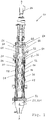
- the device 10 comprises a vertically aligned housing 12 with a heatable housing jacket 14, which encloses a treatment chamber 16 and forms on its inside a rotationally symmetrical treatment surface 18 extending in the axial direction A.
- the device further comprises a material inlet 20 leading through the housing jacket 14 for introducing the material to be treated into the treatment chamber 16 and a material outlet 22.
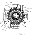
- the material inlet 20 oriented tangentially to the housing jacket is incidentally eg in FIG Fig. 4 shown.
- a coaxially extending, via a drive unit 24 drivable rotor 26 is arranged.
- This comprises a hollow shaft 28 and distributed over the circumference, projecting from the hollow shaft 28 coating elements 30.
- the radially outermost end of the coating elements 30 is spaced from the treatment surface 18 to operate, i. during rotation of the rotor 26, to spread the material into a thin film of material on the treatment surface 18.
- the hollow shaft 28 encloses a condensation chamber 32, in which a static capacitor 34 is arranged, and has passage openings 36 through which escaping during the thermal treatment of the material escaping gaseous material components in the condensation chamber 32 in order to condense there at the capacitor 34 can.
- the coating elements are distributed over the circumference of the hollow shaft 28 distributed in a total of 16 parallel to the axial direction rows.
- all coating elements 30 are designed as a conveying element 301, which impart a conveying component to the material in the direction from the material inlet 20 to the material outlet 22.
- the conveying elements 301 include an angular web plate 38, on the outside of helically extending conveyor ribs 40 are arranged.
- the rooftop of the web plate 38 forms an axially extending shearing edge 42, which is set back relative to the radial outer edge 44 of the conveyor rib 40 and thus compared to this of the treatment surface 18 is arranged at a greater distance, as in particular Fig. 5 will be shown.
- the roof tip of the web plate 38 and the shearing edge 42 of the conveying element 301 in the embodiment shown approximately 5 mm from the treatment surface 18 spaced, while the distance of the radial outer edge 44 of the conveyor rib 40 of the treatment surface is only about 3 mm.
- a central region 46 is arranged between the inlet region 21 and the outlet region 23, in which all coating elements 30 are configured as conveying element 301.
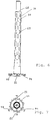
- a central region 46 is arranged between the inlet region 21 and the outlet region 23, in which all coating elements 30 are configured as conveying element 301.
- the distribution elements 302 protrude radially from the hollow shaft and in the embodiment shown comprise a multiplicity of teeth 48 arranged axially one after the other.
- the radially outermost end of the teeth 48 in each case forms a shearing edge 50 which runs parallel to the axis A of the rotor 26.
- the distribution member 302 falls primarily a distribution function with negligible or nonexistent conveying function, while the conveyor element 301 following in the circumferential direction primarily has a conveying function and secondarily - by the shearing edge 42 of the web plate - a distribution function.
- the shearing edge 50 of the teeth which is neutral due to the axial orientation, is arranged at a smaller distance from the treatment surface 18 than is the case for the shearing edge 42 of the web plate of the conveying elements, as already mentioned, and in particular in FIG Fig. 5 will be shown. Due to the resulting narrower gap for the spreading of the material, the distributing elements 302 are thus higher in shear than the conveying elements 301.
- the housing 12 has a top 52 arranged above it and sealed relative to the treatment chamber, into which the rotor 26 and the condenser 34 protrude. Specifically, for the seal between the treatment chamber 16 and upper part 52 about a rotating labyrinth seal 54 is conceivable.
- the vacuum is applied directly to the condensation chamber 32 connected to the vacuum connection 56, but not to the treatment chamber 16 sealed to the upper part 52.
- a first roof side 38a of the web plate of a first conveying element is connected to the second roof side 38b of the web plate of a second conveying element which precedes the first conveying element in the direction of rotation.
- a completely surrounding the hollow shaft 28 spray protection jacket 60 is formed, which prevents material which is exposed during the introduction into the treatment chamber of a "flash evaporation" and can be entrained by the instantaneously escaping from the material gaseous material components, on the hollow shaft 28 or in the condensation chamber 32 and ultimately can contaminate the condensate.
- the rotor 26 of the embodiment shown is cantilevered and is guided in the outlet region 23 radially through a bearing ring (not shown), which together with arranged on the hollow shaft 28, in Fig. 2 shown bearing shoes 62 forms a material-lubricated bearing.
- the bearing shoes are configured in a manner to press material into the radial gap between the bearing ring and the bearing shoe during the rotation of the rotor 26.
- the condenser 34 is arranged in a condensation chamber 32 surrounded by the hollow shaft 28, which is connected to the treatment chamber 16 via passage openings 36 for the passage of the gaseous material components escaping from the material during the thermal treatment and finally the condensation of the less volatile ones contained in these material components substances.
- the stationary capacitor 34 is stabilized via a centrally disposed pin 66, which is held in a hollow shaft 28 top closing plate 64.
- the pin is fixed at the upper end of the inner tube of the capacitor projecting beyond the outer tube.
- the condenser 34 comprises an inner tube 68 and an outer tube concentrically surrounding the inner tube 70, wherein the inner tube 68 protrudes in height above the outer tube 70 and at its upper end has the aforementioned pin 66.
- Both the inner tube 68 and the outer tube 70 each have an outer wall 681 and 701 and an inner wall 682 and 702, which are partially spaced from each other and such a gap for form the circulation of a cooling medium.
- an inner tube cooling medium circulation channel 683 is formed in the inner tube 68 and an outer tube cooling medium circulation channel 703 is formed in the outer tube 70, wherein these are flow-connected to one another.
- uniformly distributed windows 69 are arranged in the outer tube in the longitudinal direction and in the circumferential direction, which ensure that the gaseous components can also reach the inner tube 68 for condensation.
- the cooling medium inlet 74 and thedemediumauslass 78 lead radially away from the housing and are spaced apart by approximately 120 °, such as in Fig. 7 in synopsis with Fig. 8 is shown.
- heat energy is transferred from the gaseous material components via the condenser surface to the cooling medium, which ultimately leads to the condensation of the less volatile substances on the condenser surface.
- the resulting condensate flows down the condenser surface and ultimately onto the condenser bottom in the form of a sink or tub 80, from where it is discharged via corresponding, leading away from the lowest point of the capacitor bottom condensate outlets 82.
- the condensate outlets leading radially away from the housing are spaced 180 degrees, such as in FIG Fig. 7 is shown.
- the material outlet 22 is configured in the form of a subsequent to the treatment chamber and flanged to this discharge device 221.
- the device also has a concentric surrounding the capacitor 34, static cover plate 91, which is cylindrical in the embodiment shown.
- cover plate 91 which is cylindrical in the embodiment shown.
- the rotor 26 has on its inside a bushing 92 with a conveyor coil 94 in the conveying direction down.
- This bushing 92 is disposed at the height of the rotor 26, the height of the in Fig. 8 and 9 shown cover plate 91 corresponds, and formed as a counterpart to the cover plate.
- the gap between the bushing 92 and the cover plate 91 is less than the gap between the rotor 26 and the condenser 34, which is formed further above.
- the bushing 92 rotating with the rotor or the delivery spiral 94 thus becomes a very effective material delivery down and thus ensures a good seal of Kondensatauslasses 82.
Landscapes
- Chemical & Material Sciences (AREA)
- Chemical Kinetics & Catalysis (AREA)
- Organic Chemistry (AREA)
- Vaporization, Distillation, Condensation, Sublimation, And Cold Traps (AREA)
- Processing And Handling Of Plastics And Other Materials For Molding In General (AREA)
Priority Applications (4)
| Application Number | Priority Date | Filing Date | Title |
|---|---|---|---|
| EP18156079.8A EP3524331B1 (fr) | 2018-02-09 | 2018-02-09 | Dispositif de traitement thermique de matière visqueuse, en particulier de séparation thermique de composants de matière contenus dans la matière visqueuse |
| JP2019007158A JP6761059B2 (ja) | 2018-02-09 | 2019-01-18 | 粘性の材料を熱処理する、特に粘性の材料に含まれる材料成分を熱的に分離する、装置 |
| CN201910107447.1A CN110124340B (zh) | 2018-02-09 | 2019-02-02 | 用于热处理黏稠物料、尤其热分离其所含物料成分的装置 |
| US16/272,121 US10821414B2 (en) | 2018-02-09 | 2019-02-11 | Device for the thermal treatment of viscous material, in particular for the thermal separation of material components contained in viscous material |
Applications Claiming Priority (1)
| Application Number | Priority Date | Filing Date | Title |
|---|---|---|---|
| EP18156079.8A EP3524331B1 (fr) | 2018-02-09 | 2018-02-09 | Dispositif de traitement thermique de matière visqueuse, en particulier de séparation thermique de composants de matière contenus dans la matière visqueuse |
Publications (2)
| Publication Number | Publication Date |
|---|---|
| EP3524331A1 true EP3524331A1 (fr) | 2019-08-14 |
| EP3524331B1 EP3524331B1 (fr) | 2024-05-22 |
Family
ID=61189343
Family Applications (1)
| Application Number | Title | Priority Date | Filing Date |
|---|---|---|---|
| EP18156079.8A Active EP3524331B1 (fr) | 2018-02-09 | 2018-02-09 | Dispositif de traitement thermique de matière visqueuse, en particulier de séparation thermique de composants de matière contenus dans la matière visqueuse |
Country Status (4)
| Country | Link |
|---|---|
| US (1) | US10821414B2 (fr) |
| EP (1) | EP3524331B1 (fr) |
| JP (1) | JP6761059B2 (fr) |
| CN (1) | CN110124340B (fr) |
Cited By (2)
| Publication number | Priority date | Publication date | Assignee | Title |
|---|---|---|---|---|
| CH716490A1 (de) * | 2019-08-12 | 2021-02-15 | Buss Sms Canzler Gmbh | Vorrichtung zur thermischen Behandlung von Material, insbesondere zur thermischen Auftrennung von im Material enthaltenen Materialkomponenten. |
| DE102024111498A1 (de) * | 2024-04-24 | 2025-10-30 | Buss-Sms-Canzler Gmbh | Dünnschichtverdampfer |
Families Citing this family (6)
| Publication number | Priority date | Publication date | Assignee | Title |
|---|---|---|---|---|
| US11173416B2 (en) * | 2019-03-29 | 2021-11-16 | Julian Alexander Bublies | Short-path evaporator |
| FI131688B1 (en) * | 2019-06-12 | 2025-09-17 | Aurotec Gmbh | Thin-film treatment apparatus |
| US12504229B2 (en) * | 2019-12-09 | 2025-12-23 | Grant Prideco, Inc. | Apparatus for continuous thermal separation of a multi-component substance |
| EP3882479A1 (fr) | 2020-03-17 | 2021-09-22 | Dresser-Rand SAS | Dispositif de protection de couplage pour élément rotatif |
| US10953381B1 (en) | 2020-03-24 | 2021-03-23 | Tge Ip Llc | Chemical reactor with high speed rotary mixing, for catalytic thermal conversion of organic materials into diesel and other liquid fuels, and applications thereof |
| CN112221454A (zh) * | 2020-12-17 | 2021-01-15 | 蓬莱禄昊化工机械有限公司 | 一种化工生产中快速降温的化工反应釜 |
Citations (10)
| Publication number | Priority date | Publication date | Assignee | Title |
|---|---|---|---|---|
| CH453297A (de) * | 1967-03-21 | 1968-06-14 | Bayer Ag | Rotor für Dünnschichtverdampfer |
| DE1444326A1 (de) | 1962-10-14 | 1968-12-12 | Walter Buechi | Duennschichtapparat zum Verdampfen,Trennen oder Destillieren von Fluessigkeiten |
| JPH06182101A (ja) * | 1992-12-18 | 1994-07-05 | Hitachi Ltd | 立形遠心薄膜蒸発器 |
| DE19535817A1 (de) * | 1994-09-28 | 1996-04-04 | Buss Ag | Vorrichtung zur thermischen Behandlung eines viskosen Gutes, insbesondere eines thermoplastischen Elastomers |
| DE19535187A1 (de) | 1995-09-22 | 1997-03-27 | Schlueter Systems Gmbh | Trägerprofil zum Anbringen an einer Wand |
| DE10024418A1 (de) * | 2000-05-19 | 2001-11-29 | Gea Canzler Gmbh | Kurzwegverdampfer |
| AT505461A1 (de) * | 2007-06-21 | 2009-01-15 | Chemiefaser Lenzing Ag | Dünnschichtbehandlungsapparat |
| EP2039409A1 (fr) | 2007-09-22 | 2009-03-25 | Buss-SMS-Canzler GmbH | Evaporateur à court trajet avec entrée séparée de gaz au condensateur |
| EP2039408A1 (fr) | 2007-09-22 | 2009-03-25 | Buss-SMS-Canzler GmbH | Evaporateur à court trajet |
| EP2147708A1 (fr) * | 2003-10-02 | 2010-01-27 | VTU Holding GmbH | Evaporateur à couche mince |
Family Cites Families (17)
| Publication number | Priority date | Publication date | Assignee | Title |
|---|---|---|---|---|
| US1981544A (en) * | 1932-11-30 | 1934-11-20 | Gen Electric | Flash light device |
| US2546381A (en) * | 1947-03-03 | 1951-03-27 | Hurd Corp | Apparatus for concentrating liquids |
| US3292683A (en) * | 1962-10-14 | 1966-12-20 | Buchi Walter | Wiped falling film evaporator |
| CH470900A (de) * | 1966-10-14 | 1969-04-15 | Bayer Ag | Dünnschichtverdampfer |
| CH523087A (de) * | 1969-03-21 | 1972-05-31 | Luwa Ag | Dünnschichtbehandlungsapparat |
| IT1197949B (it) * | 1986-11-04 | 1988-12-21 | Montedipe Spa | Evaporatore a film sottile per fluidi ad elevata viscosita |
| JPH03238001A (ja) * | 1990-02-14 | 1991-10-23 | Shinko Pantec Co Ltd | 薄膜精留装置 |
| GB9219693D0 (en) * | 1992-09-17 | 1992-10-28 | Courtaulds Plc | Forming solutions |
| JP3302320B2 (ja) * | 1998-03-10 | 2002-07-15 | 株式会社東芝 | 遠心薄膜乾燥機 |
| CN101636416B (zh) * | 2007-01-17 | 2012-10-03 | 连津格股份公司 | 溶液的制备 |
| CN101053697A (zh) * | 2007-04-20 | 2007-10-17 | 张亚宇 | 旋转刮板蒸发器 |
| CN101362027B (zh) * | 2008-09-19 | 2011-06-29 | 无锡力马化工机械有限公司 | 一种旋转式薄膜蒸发器 |
| CN102872605A (zh) * | 2012-10-23 | 2013-01-16 | 无锡力马化工机械有限公司 | 采用齿形刮板装置的旋转式薄膜蒸发器 |
| CN105194890B (zh) * | 2015-10-09 | 2017-09-26 | 新疆丝凯食品研发中心(有限公司) | 一种提取物浓缩液的脱溶设备 |
| CN106422383B (zh) * | 2016-10-10 | 2019-02-15 | 肇庆市和邦机械制造有限公司 | 一种短程蒸发器 |
| CN106621425B (zh) * | 2016-11-17 | 2018-11-13 | 浙江工业大学 | 一种高沸点高粘度热敏性物料的蒸发装置 |
| CN206463521U (zh) * | 2016-12-30 | 2017-09-05 | 天津横天生物科技有限公司 | 一种刮板式薄膜浓缩器 |
-
2018
- 2018-02-09 EP EP18156079.8A patent/EP3524331B1/fr active Active
-
2019
- 2019-01-18 JP JP2019007158A patent/JP6761059B2/ja active Active
- 2019-02-02 CN CN201910107447.1A patent/CN110124340B/zh not_active Expired - Fee Related
- 2019-02-11 US US16/272,121 patent/US10821414B2/en active Active
Patent Citations (10)
| Publication number | Priority date | Publication date | Assignee | Title |
|---|---|---|---|---|
| DE1444326A1 (de) | 1962-10-14 | 1968-12-12 | Walter Buechi | Duennschichtapparat zum Verdampfen,Trennen oder Destillieren von Fluessigkeiten |
| CH453297A (de) * | 1967-03-21 | 1968-06-14 | Bayer Ag | Rotor für Dünnschichtverdampfer |
| JPH06182101A (ja) * | 1992-12-18 | 1994-07-05 | Hitachi Ltd | 立形遠心薄膜蒸発器 |
| DE19535817A1 (de) * | 1994-09-28 | 1996-04-04 | Buss Ag | Vorrichtung zur thermischen Behandlung eines viskosen Gutes, insbesondere eines thermoplastischen Elastomers |
| DE19535187A1 (de) | 1995-09-22 | 1997-03-27 | Schlueter Systems Gmbh | Trägerprofil zum Anbringen an einer Wand |
| DE10024418A1 (de) * | 2000-05-19 | 2001-11-29 | Gea Canzler Gmbh | Kurzwegverdampfer |
| EP2147708A1 (fr) * | 2003-10-02 | 2010-01-27 | VTU Holding GmbH | Evaporateur à couche mince |
| AT505461A1 (de) * | 2007-06-21 | 2009-01-15 | Chemiefaser Lenzing Ag | Dünnschichtbehandlungsapparat |
| EP2039409A1 (fr) | 2007-09-22 | 2009-03-25 | Buss-SMS-Canzler GmbH | Evaporateur à court trajet avec entrée séparée de gaz au condensateur |
| EP2039408A1 (fr) | 2007-09-22 | 2009-03-25 | Buss-SMS-Canzler GmbH | Evaporateur à court trajet |
Cited By (3)
| Publication number | Priority date | Publication date | Assignee | Title |
|---|---|---|---|---|
| CH716490A1 (de) * | 2019-08-12 | 2021-02-15 | Buss Sms Canzler Gmbh | Vorrichtung zur thermischen Behandlung von Material, insbesondere zur thermischen Auftrennung von im Material enthaltenen Materialkomponenten. |
| US11241637B2 (en) | 2019-08-12 | 2022-02-08 | Buss-Sms-Canzler Gmbh | Device for the thermal treatment of material, in particular for the thermal separation of material components contained in the material |
| DE102024111498A1 (de) * | 2024-04-24 | 2025-10-30 | Buss-Sms-Canzler Gmbh | Dünnschichtverdampfer |
Also Published As
| Publication number | Publication date |
|---|---|
| JP6761059B2 (ja) | 2020-09-23 |
| JP2019166518A (ja) | 2019-10-03 |
| EP3524331B1 (fr) | 2024-05-22 |
| CN110124340B (zh) | 2021-05-18 |
| US20190247823A1 (en) | 2019-08-15 |
| CN110124340A (zh) | 2019-08-16 |
| US10821414B2 (en) | 2020-11-03 |
Similar Documents
| Publication | Publication Date | Title |
|---|---|---|
| EP3524331B1 (fr) | Dispositif de traitement thermique de matière visqueuse, en particulier de séparation thermique de composants de matière contenus dans la matière visqueuse | |
| EP2212091B1 (fr) | Extrudeuse-dégazeuse destinée au dégazage d'un matériau polymère et procédé de dégazage d'un sirop de polymères, solvants et/ou monomères à l'aide d'une extrudeuse-dégazeuse | |
| EP1135245B1 (fr) | Procede pour le traitement d'un polycondensat thermoplastique | |
| DD266276A5 (de) | Duennschichtverdampfer fuer hochviskose fluessigkeiten | |
| EP3777987A1 (fr) | Dispositif de traitement thermique de matériau, en particulier de séparation thermique des composants de matériau contenus dans le matériau | |
| DE69512278T2 (de) | Verfahren zum einspritzen von einem produckt in eine flüssigkeit | |
| EP3318311B1 (fr) | Dispositif de traitement de couche mince | |
| DE69019623T2 (de) | Dünnschichtverdampfer. | |
| EP3103538B1 (fr) | Vaporisateur a couche mince | |
| EP0927095B1 (fr) | Dispositif pour homogeneiser, melanger et/ou granuler des matieres chimiques | |
| CH619150A5 (fr) | ||
| DE3022731A1 (de) | Verfahren und vorrichtung zum thermischen behandeln von fliessfaehigem gut | |
| DE1930221A1 (de) | Vorrichtung zum Behandeln von Fluessigkeiten in duennen Schichten,insbesondere Duennschichtverdampfer | |
| EP1477223B1 (fr) | Reacteur de grand volume avec plusieurs chambres | |
| DE69614345T2 (de) | Rührvorrichtung für viskose Flüssigkeiten und Verfahren zur Herstellung von Polycarbonat unter Verwendung der Rührvorrichtung | |
| DE2825857C2 (de) | Verfahren und Vorrichtung zur Herstellung von pulverförmigem Polycarbonat aus einer Polycarbonatlösung | |
| CH689444A5 (de) | Vorrichtung zur thermischen Behandlung eines viskosen Gutes, insbesondere eines thermoplastischen Elastomers. | |
| EP0451602B1 (fr) | Procédé continu pour concentrer des solutions polymères jusqu'à une spécification demandée des solvants résiduels | |
| WO1997031766A2 (fr) | Machine a vis sans fin | |
| CH434204A (de) | Trenn-Kolonne zur Nassreinigung von Gasen oder zur Destillation oder Trennung von Flüssigkeiten | |
| DE3544642A1 (de) | Verfahren und vorrichtung zum absondern einer phase aus einem heterogenen gemisch von unvermischbaren fluessigkeiten | |
| DE2848273C2 (de) | Vorrichtung zum Aufbereiten von durch Wärme plastifizierbaren Kunststoffen und polymeren Materialien | |
| DE1642910A1 (de) | Vorrichtung zum Behandeln von Fluessigkeiten in duennen Schichten | |
| EP0821010A1 (fr) | Procédé et appareil pour éliminer des composants volatiles des solutions ou suspensions très visqueuses | |
| DE1813956C (de) | Reaktor und dessen Verwendung zur Behandlung viskoser Ausgangs massen |
Legal Events
| Date | Code | Title | Description |
|---|---|---|---|
| PUAI | Public reference made under article 153(3) epc to a published international application that has entered the european phase |
Free format text: ORIGINAL CODE: 0009012 |
|
| STAA | Information on the status of an ep patent application or granted ep patent |
Free format text: STATUS: THE APPLICATION HAS BEEN PUBLISHED |
|
| AK | Designated contracting states |
Kind code of ref document: A1 Designated state(s): AL AT BE BG CH CY CZ DE DK EE ES FI FR GB GR HR HU IE IS IT LI LT LU LV MC MK MT NL NO PL PT RO RS SE SI SK SM TR |
|
| AX | Request for extension of the european patent |
Extension state: BA ME |
|
| STAA | Information on the status of an ep patent application or granted ep patent |
Free format text: STATUS: REQUEST FOR EXAMINATION WAS MADE |
|
| 17P | Request for examination filed |
Effective date: 20200210 |
|
| RBV | Designated contracting states (corrected) |
Designated state(s): AL AT BE BG CH CY CZ DE DK EE ES FI FR GB GR HR HU IE IS IT LI LT LU LV MC MK MT NL NO PL PT RO RS SE SI SK SM TR |
|
| STAA | Information on the status of an ep patent application or granted ep patent |
Free format text: STATUS: EXAMINATION IS IN PROGRESS |
|
| 17Q | First examination report despatched |
Effective date: 20230328 |
|
| GRAP | Despatch of communication of intention to grant a patent |
Free format text: ORIGINAL CODE: EPIDOSNIGR1 |
|
| STAA | Information on the status of an ep patent application or granted ep patent |
Free format text: STATUS: GRANT OF PATENT IS INTENDED |
|
| INTG | Intention to grant announced |
Effective date: 20240207 |
|
| GRAS | Grant fee paid |
Free format text: ORIGINAL CODE: EPIDOSNIGR3 |
|
| GRAA | (expected) grant |
Free format text: ORIGINAL CODE: 0009210 |
|
| STAA | Information on the status of an ep patent application or granted ep patent |
Free format text: STATUS: THE PATENT HAS BEEN GRANTED |
|
| P01 | Opt-out of the competence of the unified patent court (upc) registered |
Effective date: 20240402 |
|
| AK | Designated contracting states |
Kind code of ref document: B1 Designated state(s): AL AT BE BG CH CY CZ DE DK EE ES FI FR GB GR HR HU IE IS IT LI LT LU LV MC MK MT NL NO PL PT RO RS SE SI SK SM TR |
|
| REG | Reference to a national code |
Ref country code: GB Ref legal event code: FG4D Free format text: NOT ENGLISH |
|
| REG | Reference to a national code |
Ref country code: CH Ref legal event code: EP |
|
| REG | Reference to a national code |
Ref country code: DE Ref legal event code: R096 Ref document number: 502018014630 Country of ref document: DE |
|
| REG | Reference to a national code |
Ref country code: IE Ref legal event code: FG4D Free format text: LANGUAGE OF EP DOCUMENT: GERMAN |
|
| REG | Reference to a national code |
Ref country code: LT Ref legal event code: MG9D |
|
| REG | Reference to a national code |
Ref country code: NL Ref legal event code: MP Effective date: 20240522 |
|
| PG25 | Lapsed in a contracting state [announced via postgrant information from national office to epo] |
Ref country code: IS Free format text: LAPSE BECAUSE OF FAILURE TO SUBMIT A TRANSLATION OF THE DESCRIPTION OR TO PAY THE FEE WITHIN THE PRESCRIBED TIME-LIMIT Effective date: 20240922 |
|
| PG25 | Lapsed in a contracting state [announced via postgrant information from national office to epo] |
Ref country code: BG Free format text: LAPSE BECAUSE OF FAILURE TO SUBMIT A TRANSLATION OF THE DESCRIPTION OR TO PAY THE FEE WITHIN THE PRESCRIBED TIME-LIMIT Effective date: 20240522 |
|
| PG25 | Lapsed in a contracting state [announced via postgrant information from national office to epo] |
Ref country code: FI Free format text: LAPSE BECAUSE OF FAILURE TO SUBMIT A TRANSLATION OF THE DESCRIPTION OR TO PAY THE FEE WITHIN THE PRESCRIBED TIME-LIMIT Effective date: 20240522 Ref country code: HR Free format text: LAPSE BECAUSE OF FAILURE TO SUBMIT A TRANSLATION OF THE DESCRIPTION OR TO PAY THE FEE WITHIN THE PRESCRIBED TIME-LIMIT Effective date: 20240522 |
|
| PG25 | Lapsed in a contracting state [announced via postgrant information from national office to epo] |
Ref country code: GR Free format text: LAPSE BECAUSE OF FAILURE TO SUBMIT A TRANSLATION OF THE DESCRIPTION OR TO PAY THE FEE WITHIN THE PRESCRIBED TIME-LIMIT Effective date: 20240823 |
|
| PG25 | Lapsed in a contracting state [announced via postgrant information from national office to epo] |
Ref country code: PT Free format text: LAPSE BECAUSE OF FAILURE TO SUBMIT A TRANSLATION OF THE DESCRIPTION OR TO PAY THE FEE WITHIN THE PRESCRIBED TIME-LIMIT Effective date: 20240923 |
|
| PG25 | Lapsed in a contracting state [announced via postgrant information from national office to epo] |
Ref country code: NL Free format text: LAPSE BECAUSE OF FAILURE TO SUBMIT A TRANSLATION OF THE DESCRIPTION OR TO PAY THE FEE WITHIN THE PRESCRIBED TIME-LIMIT Effective date: 20240522 |
|
| PG25 | Lapsed in a contracting state [announced via postgrant information from national office to epo] |
Ref country code: ES Free format text: LAPSE BECAUSE OF FAILURE TO SUBMIT A TRANSLATION OF THE DESCRIPTION OR TO PAY THE FEE WITHIN THE PRESCRIBED TIME-LIMIT Effective date: 20240522 |
|
| PG25 | Lapsed in a contracting state [announced via postgrant information from national office to epo] |
Ref country code: PL Free format text: LAPSE BECAUSE OF FAILURE TO SUBMIT A TRANSLATION OF THE DESCRIPTION OR TO PAY THE FEE WITHIN THE PRESCRIBED TIME-LIMIT Effective date: 20240522 |
|
| PG25 | Lapsed in a contracting state [announced via postgrant information from national office to epo] |
Ref country code: LV Free format text: LAPSE BECAUSE OF FAILURE TO SUBMIT A TRANSLATION OF THE DESCRIPTION OR TO PAY THE FEE WITHIN THE PRESCRIBED TIME-LIMIT Effective date: 20240522 |
|
| PG25 | Lapsed in a contracting state [announced via postgrant information from national office to epo] |
Ref country code: PT Free format text: LAPSE BECAUSE OF FAILURE TO SUBMIT A TRANSLATION OF THE DESCRIPTION OR TO PAY THE FEE WITHIN THE PRESCRIBED TIME-LIMIT Effective date: 20240923 Ref country code: PL Free format text: LAPSE BECAUSE OF FAILURE TO SUBMIT A TRANSLATION OF THE DESCRIPTION OR TO PAY THE FEE WITHIN THE PRESCRIBED TIME-LIMIT Effective date: 20240522 Ref country code: NO Free format text: LAPSE BECAUSE OF FAILURE TO SUBMIT A TRANSLATION OF THE DESCRIPTION OR TO PAY THE FEE WITHIN THE PRESCRIBED TIME-LIMIT Effective date: 20240822 Ref country code: NL Free format text: LAPSE BECAUSE OF FAILURE TO SUBMIT A TRANSLATION OF THE DESCRIPTION OR TO PAY THE FEE WITHIN THE PRESCRIBED TIME-LIMIT Effective date: 20240522 Ref country code: LV Free format text: LAPSE BECAUSE OF FAILURE TO SUBMIT A TRANSLATION OF THE DESCRIPTION OR TO PAY THE FEE WITHIN THE PRESCRIBED TIME-LIMIT Effective date: 20240522 Ref country code: IS Free format text: LAPSE BECAUSE OF FAILURE TO SUBMIT A TRANSLATION OF THE DESCRIPTION OR TO PAY THE FEE WITHIN THE PRESCRIBED TIME-LIMIT Effective date: 20240922 Ref country code: HR Free format text: LAPSE BECAUSE OF FAILURE TO SUBMIT A TRANSLATION OF THE DESCRIPTION OR TO PAY THE FEE WITHIN THE PRESCRIBED TIME-LIMIT Effective date: 20240522 Ref country code: GR Free format text: LAPSE BECAUSE OF FAILURE TO SUBMIT A TRANSLATION OF THE DESCRIPTION OR TO PAY THE FEE WITHIN THE PRESCRIBED TIME-LIMIT Effective date: 20240823 Ref country code: FI Free format text: LAPSE BECAUSE OF FAILURE TO SUBMIT A TRANSLATION OF THE DESCRIPTION OR TO PAY THE FEE WITHIN THE PRESCRIBED TIME-LIMIT Effective date: 20240522 Ref country code: ES Free format text: LAPSE BECAUSE OF FAILURE TO SUBMIT A TRANSLATION OF THE DESCRIPTION OR TO PAY THE FEE WITHIN THE PRESCRIBED TIME-LIMIT Effective date: 20240522 Ref country code: BG Free format text: LAPSE BECAUSE OF FAILURE TO SUBMIT A TRANSLATION OF THE DESCRIPTION OR TO PAY THE FEE WITHIN THE PRESCRIBED TIME-LIMIT Effective date: 20240522 Ref country code: RS Free format text: LAPSE BECAUSE OF FAILURE TO SUBMIT A TRANSLATION OF THE DESCRIPTION OR TO PAY THE FEE WITHIN THE PRESCRIBED TIME-LIMIT Effective date: 20240822 |
|
| PG25 | Lapsed in a contracting state [announced via postgrant information from national office to epo] |
Ref country code: DK Free format text: LAPSE BECAUSE OF FAILURE TO SUBMIT A TRANSLATION OF THE DESCRIPTION OR TO PAY THE FEE WITHIN THE PRESCRIBED TIME-LIMIT Effective date: 20240522 |
|
| PG25 | Lapsed in a contracting state [announced via postgrant information from national office to epo] |
Ref country code: EE Free format text: LAPSE BECAUSE OF FAILURE TO SUBMIT A TRANSLATION OF THE DESCRIPTION OR TO PAY THE FEE WITHIN THE PRESCRIBED TIME-LIMIT Effective date: 20240522 |
|
| PG25 | Lapsed in a contracting state [announced via postgrant information from national office to epo] |
Ref country code: CZ Free format text: LAPSE BECAUSE OF FAILURE TO SUBMIT A TRANSLATION OF THE DESCRIPTION OR TO PAY THE FEE WITHIN THE PRESCRIBED TIME-LIMIT Effective date: 20240522 |
|
| PG25 | Lapsed in a contracting state [announced via postgrant information from national office to epo] |
Ref country code: SK Free format text: LAPSE BECAUSE OF FAILURE TO SUBMIT A TRANSLATION OF THE DESCRIPTION OR TO PAY THE FEE WITHIN THE PRESCRIBED TIME-LIMIT Effective date: 20240522 Ref country code: RO Free format text: LAPSE BECAUSE OF FAILURE TO SUBMIT A TRANSLATION OF THE DESCRIPTION OR TO PAY THE FEE WITHIN THE PRESCRIBED TIME-LIMIT Effective date: 20240522 |
|
| PG25 | Lapsed in a contracting state [announced via postgrant information from national office to epo] |
Ref country code: SM Free format text: LAPSE BECAUSE OF FAILURE TO SUBMIT A TRANSLATION OF THE DESCRIPTION OR TO PAY THE FEE WITHIN THE PRESCRIBED TIME-LIMIT Effective date: 20240522 |
|
| PG25 | Lapsed in a contracting state [announced via postgrant information from national office to epo] |
Ref country code: SM Free format text: LAPSE BECAUSE OF FAILURE TO SUBMIT A TRANSLATION OF THE DESCRIPTION OR TO PAY THE FEE WITHIN THE PRESCRIBED TIME-LIMIT Effective date: 20240522 Ref country code: SK Free format text: LAPSE BECAUSE OF FAILURE TO SUBMIT A TRANSLATION OF THE DESCRIPTION OR TO PAY THE FEE WITHIN THE PRESCRIBED TIME-LIMIT Effective date: 20240522 Ref country code: RO Free format text: LAPSE BECAUSE OF FAILURE TO SUBMIT A TRANSLATION OF THE DESCRIPTION OR TO PAY THE FEE WITHIN THE PRESCRIBED TIME-LIMIT Effective date: 20240522 Ref country code: EE Free format text: LAPSE BECAUSE OF FAILURE TO SUBMIT A TRANSLATION OF THE DESCRIPTION OR TO PAY THE FEE WITHIN THE PRESCRIBED TIME-LIMIT Effective date: 20240522 Ref country code: DK Free format text: LAPSE BECAUSE OF FAILURE TO SUBMIT A TRANSLATION OF THE DESCRIPTION OR TO PAY THE FEE WITHIN THE PRESCRIBED TIME-LIMIT Effective date: 20240522 Ref country code: CZ Free format text: LAPSE BECAUSE OF FAILURE TO SUBMIT A TRANSLATION OF THE DESCRIPTION OR TO PAY THE FEE WITHIN THE PRESCRIBED TIME-LIMIT Effective date: 20240522 |
|
| PG25 | Lapsed in a contracting state [announced via postgrant information from national office to epo] |
Ref country code: IT Free format text: LAPSE BECAUSE OF FAILURE TO SUBMIT A TRANSLATION OF THE DESCRIPTION OR TO PAY THE FEE WITHIN THE PRESCRIBED TIME-LIMIT Effective date: 20240522 |
|
| REG | Reference to a national code |
Ref country code: DE Ref legal event code: R097 Ref document number: 502018014630 Country of ref document: DE |
|
| PLBE | No opposition filed within time limit |
Free format text: ORIGINAL CODE: 0009261 |
|
| STAA | Information on the status of an ep patent application or granted ep patent |
Free format text: STATUS: NO OPPOSITION FILED WITHIN TIME LIMIT |
|
| PG25 | Lapsed in a contracting state [announced via postgrant information from national office to epo] |
Ref country code: SI Free format text: LAPSE BECAUSE OF FAILURE TO SUBMIT A TRANSLATION OF THE DESCRIPTION OR TO PAY THE FEE WITHIN THE PRESCRIBED TIME-LIMIT Effective date: 20240522 |
|
| 26N | No opposition filed |
Effective date: 20250225 |
|
| REG | Reference to a national code |
Ref country code: DE Ref legal event code: R119 Ref document number: 502018014630 Country of ref document: DE |
|
| PG25 | Lapsed in a contracting state [announced via postgrant information from national office to epo] |
Ref country code: SE Free format text: LAPSE BECAUSE OF FAILURE TO SUBMIT A TRANSLATION OF THE DESCRIPTION OR TO PAY THE FEE WITHIN THE PRESCRIBED TIME-LIMIT Effective date: 20240522 |
|
| PG25 | Lapsed in a contracting state [announced via postgrant information from national office to epo] |
Ref country code: MC Free format text: LAPSE BECAUSE OF FAILURE TO SUBMIT A TRANSLATION OF THE DESCRIPTION OR TO PAY THE FEE WITHIN THE PRESCRIBED TIME-LIMIT Effective date: 20240522 |
|
| REG | Reference to a national code |
Ref country code: CH Ref legal event code: PL |
|
| PG25 | Lapsed in a contracting state [announced via postgrant information from national office to epo] |
Ref country code: LU Free format text: LAPSE BECAUSE OF NON-PAYMENT OF DUE FEES Effective date: 20250209 |
|
| PG25 | Lapsed in a contracting state [announced via postgrant information from national office to epo] |
Ref country code: CH Free format text: LAPSE BECAUSE OF NON-PAYMENT OF DUE FEES Effective date: 20250228 |
|
| GBPC | Gb: european patent ceased through non-payment of renewal fee |
Effective date: 20250209 |
|
| REG | Reference to a national code |
Ref country code: BE Ref legal event code: MM Effective date: 20250228 |
|
| PG25 | Lapsed in a contracting state [announced via postgrant information from national office to epo] |
Ref country code: DE Free format text: LAPSE BECAUSE OF NON-PAYMENT OF DUE FEES Effective date: 20250902 |
|
| PG25 | Lapsed in a contracting state [announced via postgrant information from national office to epo] |
Ref country code: GB Free format text: LAPSE BECAUSE OF NON-PAYMENT OF DUE FEES Effective date: 20250209 |
|
| PG25 | Lapsed in a contracting state [announced via postgrant information from national office to epo] |
Ref country code: FR Free format text: LAPSE BECAUSE OF NON-PAYMENT OF DUE FEES Effective date: 20250228 |
|
| PG25 | Lapsed in a contracting state [announced via postgrant information from national office to epo] |
Ref country code: BE Free format text: LAPSE BECAUSE OF NON-PAYMENT OF DUE FEES Effective date: 20250228 |
|
| PG25 | Lapsed in a contracting state [announced via postgrant information from national office to epo] |
Ref country code: IE Free format text: LAPSE BECAUSE OF NON-PAYMENT OF DUE FEES Effective date: 20250209 |
|
| PG25 | Lapsed in a contracting state [announced via postgrant information from national office to epo] |
Ref country code: AT Free format text: LAPSE BECAUSE OF NON-PAYMENT OF DUE FEES Effective date: 20250209 |
|
| REG | Reference to a national code |
Ref country code: AT Ref legal event code: MM01 Ref document number: 1688315 Country of ref document: AT Kind code of ref document: T Effective date: 20250209 |