EP3524712A1 - Procédé de fabrication d'un corps métallique poreux, et dispositif de placage - Google Patents
Procédé de fabrication d'un corps métallique poreux, et dispositif de placage Download PDFInfo
- Publication number
- EP3524712A1 EP3524712A1 EP18852709.7A EP18852709A EP3524712A1 EP 3524712 A1 EP3524712 A1 EP 3524712A1 EP 18852709 A EP18852709 A EP 18852709A EP 3524712 A1 EP3524712 A1 EP 3524712A1
- Authority
- EP
- European Patent Office
- Prior art keywords
- porous body
- power supply
- rotation shaft
- resin porous
- metal
- Prior art date
- Legal status (The legal status is an assumption and is not a legal conclusion. Google has not performed a legal analysis and makes no representation as to the accuracy of the status listed.)
- Pending
Links
- 238000007747 plating Methods 0.000 title claims abstract description 104
- 238000004519 manufacturing process Methods 0.000 title claims abstract description 28
- 229910052751 metal Inorganic materials 0.000 claims abstract description 134
- 239000002184 metal Substances 0.000 claims abstract description 134
- 239000011347 resin Substances 0.000 claims abstract description 106
- 229920005989 resin Polymers 0.000 claims abstract description 106
- 239000000843 powder Substances 0.000 claims abstract description 60
- 238000009713 electroplating Methods 0.000 claims abstract description 48
- 239000000314 lubricant Substances 0.000 claims abstract description 44
- 238000005299 abrasion Methods 0.000 claims description 19
- 230000017525 heat dissipation Effects 0.000 claims description 10
- PXHVJJICTQNCMI-UHFFFAOYSA-N Nickel Chemical compound [Ni] PXHVJJICTQNCMI-UHFFFAOYSA-N 0.000 description 18
- 239000000463 material Substances 0.000 description 14
- 239000012530 fluid Substances 0.000 description 12
- 238000000034 method Methods 0.000 description 11
- 230000002829 reductive effect Effects 0.000 description 10
- 229910052759 nickel Inorganic materials 0.000 description 9
- 230000004931 aggregating effect Effects 0.000 description 8
- 229940057995 liquid paraffin Drugs 0.000 description 8
- 238000010586 diagram Methods 0.000 description 7
- 230000006866 deterioration Effects 0.000 description 6
- 230000000694 effects Effects 0.000 description 6
- 239000006260 foam Substances 0.000 description 6
- OKTJSMMVPCPJKN-UHFFFAOYSA-N Carbon Chemical compound [C] OKTJSMMVPCPJKN-UHFFFAOYSA-N 0.000 description 5
- 208000012661 Dyskinesia Diseases 0.000 description 5
- RYGMFSIKBFXOCR-UHFFFAOYSA-N Copper Chemical compound [Cu] RYGMFSIKBFXOCR-UHFFFAOYSA-N 0.000 description 4
- XEEYBQQBJWHFJM-UHFFFAOYSA-N Iron Chemical compound [Fe] XEEYBQQBJWHFJM-UHFFFAOYSA-N 0.000 description 4
- 239000004020 conductor Substances 0.000 description 4
- 229910052802 copper Inorganic materials 0.000 description 4
- 239000010949 copper Substances 0.000 description 4
- 238000007772 electroless plating Methods 0.000 description 4
- 239000007789 gas Substances 0.000 description 4
- 150000002430 hydrocarbons Chemical class 0.000 description 4
- 239000007788 liquid Substances 0.000 description 4
- 239000011148 porous material Substances 0.000 description 4
- 238000004544 sputter deposition Methods 0.000 description 4
- UFHFLCQGNIYNRP-UHFFFAOYSA-N Hydrogen Chemical compound [H][H] UFHFLCQGNIYNRP-UHFFFAOYSA-N 0.000 description 3
- 125000004432 carbon atom Chemical group C* 0.000 description 3
- 239000006229 carbon black Substances 0.000 description 3
- 238000005260 corrosion Methods 0.000 description 3
- 230000007797 corrosion Effects 0.000 description 3
- 238000005336 cracking Methods 0.000 description 3
- 230000003247 decreasing effect Effects 0.000 description 3
- 230000005611 electricity Effects 0.000 description 3
- -1 felt Substances 0.000 description 3
- 229930195733 hydrocarbon Natural products 0.000 description 3
- 239000011261 inert gas Substances 0.000 description 3
- 239000010687 lubricating oil Substances 0.000 description 3
- 239000000203 mixture Substances 0.000 description 3
- 230000004048 modification Effects 0.000 description 3
- 238000012986 modification Methods 0.000 description 3
- 238000007254 oxidation reaction Methods 0.000 description 3
- CURLTUGMZLYLDI-UHFFFAOYSA-N Carbon dioxide Chemical compound O=C=O CURLTUGMZLYLDI-UHFFFAOYSA-N 0.000 description 2
- JOYRKODLDBILNP-UHFFFAOYSA-N Ethyl urethane Chemical compound CCOC(N)=O JOYRKODLDBILNP-UHFFFAOYSA-N 0.000 description 2
- 229910001200 Ferrotitanium Inorganic materials 0.000 description 2
- PPBRXRYQALVLMV-UHFFFAOYSA-N Styrene Chemical compound C=CC1=CC=CC=C1 PPBRXRYQALVLMV-UHFFFAOYSA-N 0.000 description 2
- RTAQQCXQSZGOHL-UHFFFAOYSA-N Titanium Chemical compound [Ti] RTAQQCXQSZGOHL-UHFFFAOYSA-N 0.000 description 2
- 239000003054 catalyst Substances 0.000 description 2
- 229910002804 graphite Inorganic materials 0.000 description 2
- 239000010439 graphite Substances 0.000 description 2
- 239000012535 impurity Substances 0.000 description 2
- 229910052742 iron Inorganic materials 0.000 description 2
- 238000012423 maintenance Methods 0.000 description 2
- 239000002905 metal composite material Substances 0.000 description 2
- 239000012188 paraffin wax Substances 0.000 description 2
- 239000003208 petroleum Substances 0.000 description 2
- 229930195734 saturated hydrocarbon Natural products 0.000 description 2
- 229910001220 stainless steel Inorganic materials 0.000 description 2
- 239000010935 stainless steel Substances 0.000 description 2
- 239000000758 substrate Substances 0.000 description 2
- 239000010936 titanium Substances 0.000 description 2
- KWSLGOVYXMQPPX-UHFFFAOYSA-N 5-[3-(trifluoromethyl)phenyl]-2h-tetrazole Chemical compound FC(F)(F)C1=CC=CC(C2=NNN=N2)=C1 KWSLGOVYXMQPPX-UHFFFAOYSA-N 0.000 description 1
- 101100165186 Caenorhabditis elegans bath-34 gene Proteins 0.000 description 1
- 101100493710 Caenorhabditis elegans bath-40 gene Proteins 0.000 description 1
- 239000004215 Carbon black (E152) Substances 0.000 description 1
- 230000002378 acidificating effect Effects 0.000 description 1
- 230000004913 activation Effects 0.000 description 1
- 239000011149 active material Substances 0.000 description 1
- 150000001335 aliphatic alkanes Chemical class 0.000 description 1
- 125000001931 aliphatic group Chemical group 0.000 description 1
- 229910003481 amorphous carbon Inorganic materials 0.000 description 1
- 239000007864 aqueous solution Substances 0.000 description 1
- 150000004945 aromatic hydrocarbons Chemical class 0.000 description 1
- 101150062523 bath-39 gene Proteins 0.000 description 1
- 239000011230 binding agent Substances 0.000 description 1
- 229910052799 carbon Inorganic materials 0.000 description 1
- 229910002092 carbon dioxide Inorganic materials 0.000 description 1
- 239000001569 carbon dioxide Substances 0.000 description 1
- 239000003153 chemical reaction reagent Substances 0.000 description 1
- 239000003638 chemical reducing agent Substances 0.000 description 1
- 238000005660 chlorination reaction Methods 0.000 description 1
- 238000004140 cleaning Methods 0.000 description 1
- 239000010779 crude oil Substances 0.000 description 1
- 238000004821 distillation Methods 0.000 description 1
- 239000004519 grease Substances 0.000 description 1
- 230000020169 heat generation Effects 0.000 description 1
- 238000010438 heat treatment Methods 0.000 description 1
- 239000001257 hydrogen Substances 0.000 description 1
- 229910052739 hydrogen Inorganic materials 0.000 description 1
- 238000007654 immersion Methods 0.000 description 1
- 150000002739 metals Chemical class 0.000 description 1
- LNOPIUAQISRISI-UHFFFAOYSA-N n'-hydroxy-2-propan-2-ylsulfonylethanimidamide Chemical compound CC(C)S(=O)(=O)CC(N)=NO LNOPIUAQISRISI-UHFFFAOYSA-N 0.000 description 1
- LGQLOGILCSXPEA-UHFFFAOYSA-L nickel sulfate Chemical compound [Ni+2].[O-]S([O-])(=O)=O LGQLOGILCSXPEA-UHFFFAOYSA-L 0.000 description 1
- 229910000363 nickel(II) sulfate Inorganic materials 0.000 description 1
- 239000004745 nonwoven fabric Substances 0.000 description 1
- 150000002894 organic compounds Chemical class 0.000 description 1
- 229910052763 palladium Inorganic materials 0.000 description 1
- KDLHZDBZIXYQEI-UHFFFAOYSA-N palladium Substances [Pd] KDLHZDBZIXYQEI-UHFFFAOYSA-N 0.000 description 1
- 239000002245 particle Substances 0.000 description 1
- 238000002360 preparation method Methods 0.000 description 1
- 230000002265 prevention Effects 0.000 description 1
- 239000002994 raw material Substances 0.000 description 1
- 238000009751 slip forming Methods 0.000 description 1
- 229910001379 sodium hypophosphite Inorganic materials 0.000 description 1
- 150000003464 sulfur compounds Chemical class 0.000 description 1
- 239000002759 woven fabric Substances 0.000 description 1
Images



Classifications
-
- C—CHEMISTRY; METALLURGY
- C25—ELECTROLYTIC OR ELECTROPHORETIC PROCESSES; APPARATUS THEREFOR
- C25D—PROCESSES FOR THE ELECTROLYTIC OR ELECTROPHORETIC PRODUCTION OF COATINGS; ELECTROFORMING; APPARATUS THEREFOR
- C25D1/00—Electroforming
- C25D1/04—Wires; Strips; Foils
-
- C—CHEMISTRY; METALLURGY
- C25—ELECTROLYTIC OR ELECTROPHORETIC PROCESSES; APPARATUS THEREFOR
- C25D—PROCESSES FOR THE ELECTROLYTIC OR ELECTROPHORETIC PRODUCTION OF COATINGS; ELECTROFORMING; APPARATUS THEREFOR
- C25D5/00—Electroplating characterised by the process; Pretreatment or after-treatment of workpieces
- C25D5/54—Electroplating of non-metallic surfaces
- C25D5/56—Electroplating of non-metallic surfaces of plastics
-
- C—CHEMISTRY; METALLURGY
- C25—ELECTROLYTIC OR ELECTROPHORETIC PROCESSES; APPARATUS THEREFOR
- C25D—PROCESSES FOR THE ELECTROLYTIC OR ELECTROPHORETIC PRODUCTION OF COATINGS; ELECTROFORMING; APPARATUS THEREFOR
- C25D1/00—Electroforming
-
- C—CHEMISTRY; METALLURGY
- C25—ELECTROLYTIC OR ELECTROPHORETIC PROCESSES; APPARATUS THEREFOR
- C25D—PROCESSES FOR THE ELECTROLYTIC OR ELECTROPHORETIC PRODUCTION OF COATINGS; ELECTROFORMING; APPARATUS THEREFOR
- C25D1/00—Electroforming
- C25D1/08—Perforated or foraminous objects, e.g. sieves
-
- C—CHEMISTRY; METALLURGY
- C25—ELECTROLYTIC OR ELECTROPHORETIC PROCESSES; APPARATUS THEREFOR
- C25D—PROCESSES FOR THE ELECTROLYTIC OR ELECTROPHORETIC PRODUCTION OF COATINGS; ELECTROFORMING; APPARATUS THEREFOR
- C25D7/00—Electroplating characterised by the article coated
- C25D7/06—Wires; Strips; Foils
- C25D7/0614—Strips or foils
- C25D7/0657—Conducting rolls
-
- H—ELECTRICITY
- H01—ELECTRIC ELEMENTS
- H01M—PROCESSES OR MEANS, e.g. BATTERIES, FOR THE DIRECT CONVERSION OF CHEMICAL ENERGY INTO ELECTRICAL ENERGY
- H01M4/00—Electrodes
- H01M4/02—Electrodes composed of, or comprising, active material
- H01M4/64—Carriers or collectors
- H01M4/66—Selection of materials
-
- H—ELECTRICITY
- H01—ELECTRIC ELEMENTS
- H01R—ELECTRICALLY-CONDUCTIVE CONNECTIONS; STRUCTURAL ASSOCIATIONS OF A PLURALITY OF MUTUALLY-INSULATED ELECTRICAL CONNECTING ELEMENTS; COUPLING DEVICES; CURRENT COLLECTORS
- H01R39/00—Rotary current collectors, distributors or interrupters
- H01R39/02—Details for dynamo electric machines
- H01R39/38—Brush holders
-
- H—ELECTRICITY
- H01—ELECTRIC ELEMENTS
- H01R—ELECTRICALLY-CONDUCTIVE CONNECTIONS; STRUCTURAL ASSOCIATIONS OF A PLURALITY OF MUTUALLY-INSULATED ELECTRICAL CONNECTING ELEMENTS; COUPLING DEVICES; CURRENT COLLECTORS
- H01R39/00—Rotary current collectors, distributors or interrupters
- H01R39/02—Details for dynamo electric machines
- H01R39/56—Devices for lubricating or polishing slip-rings or commutators during operation of the collector
-
- H—ELECTRICITY
- H01—ELECTRIC ELEMENTS
- H01R—ELECTRICALLY-CONDUCTIVE CONNECTIONS; STRUCTURAL ASSOCIATIONS OF A PLURALITY OF MUTUALLY-INSULATED ELECTRICAL CONNECTING ELEMENTS; COUPLING DEVICES; CURRENT COLLECTORS
- H01R39/00—Rotary current collectors, distributors or interrupters
- H01R39/02—Details for dynamo electric machines
- H01R39/38—Brush holders
- H01R39/381—Brush holders characterised by the application of pressure to brush
-
- Y—GENERAL TAGGING OF NEW TECHNOLOGICAL DEVELOPMENTS; GENERAL TAGGING OF CROSS-SECTIONAL TECHNOLOGIES SPANNING OVER SEVERAL SECTIONS OF THE IPC; TECHNICAL SUBJECTS COVERED BY FORMER USPC CROSS-REFERENCE ART COLLECTIONS [XRACs] AND DIGESTS
- Y02—TECHNOLOGIES OR APPLICATIONS FOR MITIGATION OR ADAPTATION AGAINST CLIMATE CHANGE
- Y02E—REDUCTION OF GREENHOUSE GAS [GHG] EMISSIONS, RELATED TO ENERGY GENERATION, TRANSMISSION OR DISTRIBUTION
- Y02E60/00—Enabling technologies; Technologies with a potential or indirect contribution to GHG emissions mitigation
- Y02E60/10—Energy storage using batteries
Definitions
- the present invention relates to a method for producing a metal porous body and a plating apparatus.
- a sheet-like metal porous body having a skeleton with a three-dimensional network structure has been used for various uses such as a filter that requires heat resistance, a battery electrode plate, a catalyst support, and a metal composite.
- a method for producing the metal porous body a method has been known in which, after the surface of the skeleton of a resin porous body is subjected to electrical conduction treatment, metal plating is performed by means of electroplating treatment and treatment of removing the resin porous body is performed, thereby obtaining a metal porous body (see, for example, PATENT LITERATURE 1).
- electroplating treatment is repeatedly performed in a plurality of plating tanks while the resin porous body is being sequentially fed by feeding rollers and electrode rollers that serve as power supply cathodes outside the plating tanks.
- a current is sent to each electrode roller by bringing a rotation shaft of the electrode roller and a power supply brush into sliding contact with each other (see, for example, PATENT LITERATURE 2).
- a method for producing a metal porous body according to the present disclosure is a method for producing a metal porous body, including the steps of: performing electrical conduction treatment on a surface of a skeleton of a sheet-like resin porous body having the skeleton with a three-dimensional network structure, to obtain a conductive resin porous body having a conductive layer; performing electroplating treatment on a surface of a skeleton of the conductive resin porous body to obtain a plated resin porous body having a metal plating layer; and performing treatment of removing at least the resin porous body from the plated resin porous body to obtain a metal porous body, wherein, in the electroplating treatment, power is supplied to a rotation shaft of a rotating electrode roller while a contact surface of a power supply brush composed of a sintered body is brought into sliding contact with the rotation shaft with a lubricant, not containing conductive metal powder, interposed therebetween.
- Not containing conductive metal powder means to include not only the case where conductive metal powder is not contained at all but also the case where conductive metal powder is contained in a certain amount such that the advantageous effects of the present disclosure are achieved.
- a plating apparatus is a plating apparatus for performing electroplating treatment on a surface of a skeleton of a conductive resin porous body obtained by forming a conductive layer on a surface of a skeleton of a sheet-like resin porous body having the skeleton with a three-dimensional network structure, to form a metal plating layer
- the plating apparatus including: a plating tank; an electrode roller having a rotatable rotation shaft and configured to feed the conductive resin porous body to the plating tank by rotating the rotation shaft; and a power supply brush composed of a sintered body, wherein the power supply brush has a contact surface that is brought into sliding contact with the rotation shaft of the electrode roller with a lubricant, not containing conductive metal powder, interposed therebetween.
- the surface of the power supply brush for which a sintered body is used is porous, thus the frictional resistance between the power supply brush and the rotation shaft of the electrode roller increases, and jerkiness (rotational failure) easily occurs at the electrode roller that rotates at a low speed.
- jerkiness occurs, if the amount of plating on the resin porous body is small in the electroplating treatment, the plating thickness of a produced metal porous body is small, so that the skeleton of the metal porous body may be cracked thus reducing the strength, resulting in a decrease in the quality of the metal porous body.
- an object of the present disclosure is to provide a method for producing a metal porous body and a plating apparatus that can improve the quality of the metal porous body.
- the contact surface of the power supply brush composed of a sintered body is brought into sliding contact with the rotation shaft of the electrode roller with the lubricant interposed therebetween, and thus the frictional resistance between the power supply brush and the rotation shaft of the electrode roller can be reduced. Accordingly, even when the amount of plating is reduced in the electroplating treatment, occurrence of jerkiness at the rotation shaft of the electrode roller can be inhibited. As a result, occurrence of cracking, in a metal porous body obtained after the electroplating treatment, that reduces the strength of the metal porous body can be inhibited, and thus the quality of the metal porous body can be improved.
- a method in which a conductive material such as metal powder is mixed into the fluid to cause the fluid itself to have electrical conductivity is adopted.
- conductive metal powder is contained in a lubricant that corresponds to the fluid, when the lubricant is used over a long period of time, the metal powder may be oxidized, resulting in significant deterioration of electrical conductivity, and the metal powder may aggregate into lumps and accumulate between the contact surface of the power supply brush and the rotation shaft of the electrode roller, thereby decreasing the contact area between the contact surface and the rotation shaft of the electrode roller.
- the lubricant does not contain conductive metal powder, deterioration of electrical conductivity due to oxidization of metal powder can be prevented.
- metal powder can be prevented from aggregating into lumps and accumulating between the contact surface of the power supply brush and the rotation shaft of the electrode roller, a decrease in the contact area between the contact surface and the rotation shaft of the electrode roller can be prevented, and the contact area that is stable can be ensured.
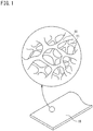
- FIG. 1 is a schematic diagram showing a metal porous body.
- the metal porous body 10 has a sheet-like appearance and has a skeleton 11 forming a three-dimensional network structure. A large number of pores defined by the three-dimensional network structure are formed so as to be arranged from the surface of the metal porous body 10 to the interior of the metal porous body 10.
- the metal porous body 10 can be used, for example, as a positive electrode plate 21 of a battery 20 as shown in FIG. 2 . That is, as shown in FIG. 2 , the battery 20 in which the metal porous body 10 according to the present embodiment is used mainly includes the positive electrode plate 21, a separator 22, and a negative electrode plate 23 that are disposed within a casing 24. The positive electrode plate 21, the separator 22, and the negative electrode plate 23 are disposed within the casing 24 in a state of being layered. The layered body of the positive electrode plate 21, the separator 22, and the negative electrode plate 23 is held in a wound state.
- the positive electrode plate 21 includes the metal porous body 10 according to the present embodiment and an active material (not shown) with which the metal porous body 10 is filled.
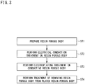
- FIG. 3 is a flowchart showing a method for producing the metal porous body 10 according to an embodiment of the present invention. Hereinafter, the flow of the entirety of the method for producing the metal porous body 10 will be described with reference to FIG. 3 .
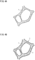
- FIG. 4A is an enlarged schematic view of the surface of a resin porous body 1 serving as a base.
- a large number of pores defined by a three-dimensional network structure are formed so as to be arranged from the surface of the resin porous body 1 to the interior of the resin porous body 1.
- step ST2 electrical conduction treatment is performed on the surface of the skeleton of the resin porous body 1 (step ST2).
- a conductive resin porous body 3 having a conductive layer 2 formed by a thin electric conductor on the surface of the skeleton of the resin porous body 1 as shown in FIG. 4B can be obtained.
- step ST3 electroplating treatment is performed on the surface of the skeleton of the conductive resin porous body 3 (step ST3).
- a plated resin porous body 5 having a metal plating layer 4 formed on the surface of the skeleton of the conductive resin porous body 3 as shown in FIG. 4C can be obtained.
- step ST4 treatment of removing the resin porous body 1, which is the base, from the plated resin porous body 5 is performed.
- the resin porous body 1 is eliminated by burning or the like, whereby the metal porous body 10 in which only the metal plating layer 4 is left can be obtained (see FIG. 4D ).
- each step will be sequentially described in detail.
- the sheet-like resin porous body 1 having the skeleton with the three-dimensional network structure is prepared.
- the material of the resin porous body 1 include a resin foam, a nonwoven fabric, felt, and a woven fabric, and these materials may be combined as necessary.
- the material of the resin porous body 1 is not particularly limited, but a material that can be eliminated by burning after the metal plating layer 4 is formed on the surface of the skeleton by the electroplating treatment is preferable.
- the material of the resin porous body 1 is preferably a flexible material, since a sheet-like material is particularly easily broken due to handling thereof if the rigidity of the material is high.
- a resin foam is preferably used as the material of the resin porous body 1.
- the resin foam only needs to be porous, and a known or commercially-available one can be used. Examples of such a material include foamed urethane and foamed styrene. Among them, foamed urethane is particularly preferable from the viewpoint of having a high porosity.
- the thickness, the porosity, and the average pore size of the resin foam are not particularly limited in the present invention, and can be set as appropriate according to use.
- the thickness of the resin foam in the present embodiment is, for example, 1.0 mm to 2.5 mm, preferably 1.0 mm to 1.6 mm, and more preferably 1.0 mm to 1.3 mm.
- the average pore size of the resin foam in the present embodiment is, for example, 250 ⁇ m to 500 ⁇ m, preferably 300 ⁇ m to 450 ⁇ m, and more preferably 300 ⁇ m to 400 ⁇ m.
- the method for the electrical conduction treatment is not particularly limited as long as the conductive layer 2 can be formed on the surface of the skeleton of the resin porous body 1.
- the material for forming the conductive layer 2 include metals such as nickel, titanium, and stainless steel, and carbon powder such as graphite and amorphous carbon including carbon black, etc. Among them, particularly, carbon powder is preferable, and carbon black is more preferable.
- the conductive layer 2 only needs to be continuously formed on the surface of the skeleton of the resin porous body 1.
- the weight of the conductive layer 2 per unit area is not particularly limited, and may be normally about 5 g/m 2 to about 15 g/m 2 , and preferably about 7 g/m 2 to about 10 g/m 2 .
- the electrical conduction treatment for example, in the case of using nickel, electroless plating treatment, sputtering treatment, and the like are preferable.
- a material such as carbon black, graphite, or a metal such as titanium and stainless steel
- treatment in which a mixture obtained by adding a binder to fine powder of the material is applied to the surface of the skeleton of the resin porous body 1 is preferable.
- the resin porous body 1 may be immersed into a known electroless nickel plating bath such as a nickel sulfate aqueous solution containing sodium hypophosphite as a reducing agent. Before the immersion into the plating bath, the resin porous body 1 may be immersed as necessary into an activation liquid containing a very small amount of palladium ions (a cleaning liquid manufactured by JAPAN KANIGEN Co., Ltd.) or the like.
- a known electroless nickel plating bath such as a nickel sulfate aqueous solution containing sodium hypophosphite as a reducing agent.
- an activation liquid containing a very small amount of palladium ions a cleaning liquid manufactured by JAPAN KANIGEN Co., Ltd.
- the resin porous body 1 may be attached to a substrate holder, then a DC voltage may be applied between the substrate holder and a target (nickel) while inert gas is being introduced, whereby ionized inert gas may be collided against the nickel, and the blown nickel particles may be accumulated on the surface of the skeleton of the resin porous body 1.
- a DC voltage may be applied between the substrate holder and a target (nickel) while inert gas is being introduced, whereby ionized inert gas may be collided against the nickel, and the blown nickel particles may be accumulated on the surface of the skeleton of the resin porous body 1.
- the thickness of the metal plating layer is increased by at least one of the above electroless plating treatment and the above sputtering treatment, it is not necessary to perform electroplating treatment.
- a method is preferably adopted in which, as described above, first, electrical conduction treatment is performed on the resin porous body 1, and then the metal plating layer 4 is formed on the conductive resin porous body 3 by electroplating treatment.
- the electroplating treatment only needs to be performed according to an ordinary method.
- a known or commercially-available one can be used as a plating bath.
- the plating bath include a Watts bath, a chlorination bath, and a sulfamic acid bath.
- the conductive resin porous body 3 is immersed into the plating bath, the conductive resin porous body 3 and a counter electrode plate of a plating metal are connected to a cathode and an anode, respectively, and a DC or pulse interrupted current is applied thereto, whereby the metal plating layer 4 can be further formed on the conductive layer 2 of the conductive resin porous body 3.
- the metal plating layer 4 only needs to be formed on the conductive layer 2 such that the conductive layer 2 is not exposed (see FIG. 4C ).
- FIG. 5 is a side cross-sectional view showing an example of a plating apparatus 30 that continuously performs electroplating treatment on the sheet-like conductive resin porous body 3.
- the plating apparatus 30 of the present embodiment is configured to feed the sheet-like conductive resin porous body 3 from the left side to the right side in FIG. 5 , and includes a first plating tank 31, a second plating tank 32 disposed at the downstream side of the first plating tank 31, and a power supply device 50 (see FIG. 7 ).
- the first plating tank 31 includes a plating bath 33, a cylindrical electrode 34 (cylindrical cathode), and an anode 35 (cylindrical anode) provided on an inner wall of a container.
- a plating bath 33 a cylindrical electrode 34 (cylindrical cathode), and an anode 35 (cylindrical anode) provided on an inner wall of a container.
- the second plating tank 32 includes a plurality of tanks 36 for forming the metal plating layer 4 on the other surface side (the upper surface side in FIG. 5 ) of the conductive resin porous body 3.
- the conductive resin porous body 3 undergoes metal plating by being sequentially fed and passing through plating baths 39 in a state of being held between a plurality of feeding rollers 37 and a plurality of electrode rollers 38, which are disposed adjacent to the respective tanks 36.
- an anode 40 is provided at the other surface side of the conductive resin porous body 3 with the plating bath 39 interposed therebetween.
- the metal plating layer 4 is formed on the other surface side of the conductive resin porous body 3.
- FIG. 6 is a plan view showing a structure for supplying power to the rotation shafts 38a of the electrode roller 38.
- the rotation shafts 38a of the electrode roller 38 are provided at both axial end portions of the electrode roller 38 which rotates in contact with the sheet-like conductive resin porous body 3.
- Each of the rotation shafts 38a of each electrode roller 38 is supplied with power by a plurality of power supply brushes 51 each of which is in sliding contact with the outer circumferential surface of the rotation shaft 38a.
- Each power supply brush 51 is composed of, for example, a sintered body containing copper as a main component, such that a large current can be applied to the rotation shaft 38a of the electrode roller 38.
- the "main component” refers to a component having a highest mass content, and impurities may be contained as long as the advantageous effects of the present embodiment are achieved.
- Each of the rotation shafts 38a of each electrode roller 38 is composed of a sintered body made of metal, and plating can be performed on the rotation shaft 38a from the viewpoint of prevention of corrosion.
- Each power supply brush 51 may be composed of a sintered body containing a main component other than copper, such as iron.
- Each power supply brush 51 is designed to be abraded against the rotation shaft 38a of the electrode roller 38.
- the coefficient of dynamic friction of each power supply brush 51 is about 0.01 to 0.40 and preferably 0.10 to 0.30. This is because: when the coefficient of dynamic friction is less than these ranges, it is disadvantageous in cost; and when the coefficient of dynamic friction is greater than these ranges, the problem arises that the slidability is deteriorated and the amount of abrasion is increased.
- FIG. 7 is a cross-sectional view showing the power supply device 50 including the plurality of power supply brushes 51.
- the power supply device 50 is provided at each of both axial end portions of the electrode roller 38.
- the power supply device 50 of the present embodiment includes the plurality of (in this example, two) power supply brushes 51, a plurality of biasing members 52 that press and bias the respective power supply brushes 51 against the outer circumferential surface of the rotation shaft 38a of the electrode roller 38, and a casing 53.
- the casing 53 is formed, for example, by a metal member having electric conductivity.
- the casing 53 of the present embodiment is formed in a rectangular cross-sectional shape so as to surround the rotation shaft 38a of the electrode roller 38, and the biasing members 52 are attached to two surfaces, that is, the upper surface and the left surface, among four inner surfaces of the casing 53.
- Each biasing member 52 is not particularly limited as long as the biasing member 52 presses and biases the power supply brush 51 against the outer circumferential surface of the rotation shaft 38a of the electrode roller 38.
- each biasing member 52 of the present embodiment is formed by a plate spring that is bent in an S cross-sectional shape.
- One end portion of each biasing member 52 is attached to the corresponding inner surface of the casing 53, for example, by a fixing plate 56A and a bolt 57A, and the power supply brush 51 is connected to the other end portion of each biasing member 52, for example, by a fixing plate 56B and a bolt 57B.
- contact surfaces 51a (described later) of the two power supply brushes 51 are pressed against the outer circumferential surface of the rotation shaft 38a of the electrode roller 38 from the upper side and the left side in FIG. 7 by the biasing force of the corresponding biasing members 52.
- Each biasing member 52 is preferably formed by a metal member having both excellent electric conductivity and excellent heat dissipation.
- Each biasing member 52 of the present embodiment is formed by a metal member obtained by tinning copper having electric conductivity and having excellent heat dissipation.
- the fixing plates 56A and 56B also have heat dissipation.
- the biasing member 52 and the fixing plates 56A and 56B serve as a heat dissipation member that dissipates heat generated in the power supply brush 51 connected to this biasing member 52, to the outside.
- the heat dissipation member connected to the power supply brush 51 may be formed by a member other than the biasing member 52 and the fixing plates 56A and 56B, or may be formed by the biasing member 52, the fixing plates 56A and 56B, and the casing 53.
- each power supply brush 51 a surface that faces the outer circumferential surface of the rotation shaft 38a of the electrode roller 38 is the contact surface 51a that is in sliding contact with the outer circumferential surface.
- the contact surface 51a is formed in a circular arc shape along the outer circumferential surface of the rotation shaft 38a of the electrode roller 38.
- a lubricant 58 not containing conductive metal powder is applied to the contact surface 51a.
- “Not containing conductive metal powder” means to include not only the case where conductive metal powder is not contained at all but also the case where conductive metal powder is contained in a certain amount such that the advantageous effects of the present embodiment are achieved.
- a lubricating oil that is a liquid, or grease is used as the lubricant 58.
- liquid paraffin which is a lubricating oil
- paraffin is a type of hydrocarbon compound (organic compound), is a generic term for alkanes having 20 or more carbon atoms (chain saturated hydrocarbons having the general formula of C n H 2n+2 ), and is considered synonymous for aliphatic saturated hydrocarbons C n H 2n+2 in some cases regardless of the number of carbon atoms.
- paraffin is a mixture of hydrocarbons obtained from petroleum or crude oil through processes such as distillation and refinement and is a colorless and transparent liquid. Liquid paraffin can be considered as a pure hydrocarbon since liquid paraffin is highly purified by removing impurities such as aromatic hydrocarbons and sulfur compounds contained in lube-oil distillate of petroleum that is a raw material.
- the liquid paraffin is a mixture (weight-average molecular weight: 483) of hydrocarbons (the number of carbon atoms is about 15 to 20), and a reagent having a purity of about 95% equivalent to first class grade is preferably used.
- the density of the liquid paraffin is preferably not less than 0.855 g/ml, and is, for example, 0.87 g/ml in the present embodiment.
- the viscosity of the liquid paraffin is preferably the low viscosity to the lower limit of the intermediate viscosity from the viewpoint of easy handling.
- the viscosity of the liquid paraffin is, for example, 75.8 cSt
- the kinetic viscosity of the liquid paraffin is, for example, 67.65 cSt (mm 2 /s at 40°C).
- the lubricant 58 is stored within a container 59 that is disposed on the lower surface within the casing 53 and below the rotation shaft 38a of the electrode roller 38.
- An opening 59a is formed at the upper side of the container 59.
- a part of the outer circumference of the rotation shaft 38a of the electrode roller 38 is immersed in the lubricant 58 within the container 59 through the opening 59a. Accordingly, by rotating the electrode roller 38, the lubricant 58 within the container 59 is applied to the entirety of the outer circumferential surface of the rotation shaft 38a.
- each power supply brush 51 can supply power to the rotation shaft 38a by bringing the contact surface 51a of the power supply brush 51 into sliding contact with the outer circumferential surface of the rotation shaft 38a with the lubricant 58 interposed therebetween.
- the dropping abrasion powder can be received within the container 59 through the opening 59a.
- FIG. 8A is a side view showing the power supply brush 51.
- FIG. 8B is a diagram of the power supply brush 51 as seen from the lower side in FIG. 8A .
- a plurality of (in this example, three) slit-shaped grooves 55 are formed on the contact surface 51a of the power supply brush 51. These grooves 55 are formed on the contact surface 51a at regular intervals in the longitudinal direction of the contact surface 51a (the right-left direction in FIG. 8A and FIG. 8 ).
- Each groove 55 is formed so as to extend in a direction crossing a tangent direction T (see FIG. 8B ) in which the contact surface 51a of the power supply brush 51 is tangent to the rotation shaft 38a of the electrode roller 38.
- each groove 55 is formed so as to extend linearly over the entirety of the contact surface 51a in the lateral direction of the contact surface 51a (the up-down direction in FIG. 8A and FIG. 8 ) in a state of being inclined at a predetermined angle (for example, 30°) relative to the lateral direction. Accordingly, abrasion powder generated on the contact surface 51a of the power supply brush 51 due to sliding contact with the rotation shaft 38a of the electrode roller 38 can be efficiently guided and discharged to the outside by the plurality of grooves 55.
- the current density during supply of power from each power supply brush 51 to the rotation shaft 38a of the electrode roller 38 (the ratio of the current to the total cross-sectional area of the power supply brush 51) is about 5 A/cm 2 to about 15 A/cm 2 and preferably 8 A/cm 2 to 13 A/cm 2 .
- the current density is less than these ranges, the size of the entire power supply device 50 is increased and the distance from the power supply device 50 to the corresponding tank 36 is lengthened, and thus voltage loss is increased.
- the current density is greater than these ranges, the temperature of the power supply brush 51 rises, and thus it is necessary to ensure heat resistance of members around the power supply brush 51, which is disadvantageous in cost.
- the weight of the metal plating layer 4 per unit area is not particularly limited, but is normally about 150 g/m 2 to about 400 g/m 2 , and the sum of the weight of the conductive layer 2 per unit area and the weight of the metal plating layer 4 per unit area is preferably not less than 200 g/m 2 and not greater than 350 g/m 2 . This is because: when the above sum is less than this range, the strength of the metal porous body may be reduced; and when the above sum is greater than this range, the power supply brush made of carbon has increased heat generation, or the amount of plating is increased, which is disadvantageous in cost.
- the electroplating treatment is not limited to the electroplating treatment of the present embodiment, and, for example, a plating treatment method using a preliminary plating tank or a plating treatment method using a preliminary plating tank and a lift type main plating tank may be adopted.
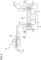
- FIG. 9 is a schematic diagram showing a modification of the plating apparatus 30.
- the plating apparatus 30 includes a preliminary plating tank 61 and a lift type main plating tank 62 disposed at the downstream side of the preliminary plating tank 61.
- the preliminary plating tank 61 includes a plating bath 63, an anode 64 (cylindrical anode), a presser roller 65, and an electrode roller 66 having a rotation shaft 66a (power supply cathode) at each end portion thereof.
- the conductive resin porous body 3 preliminarily undergoes plating on one side surface (the upper surface side in FIG. 9 ) of the conductive resin porous body 3 by being sequentially fed and passing through the inside of the plating bath 63 in a state of being held between the presser roller 65 and the electrode roller 66,
- the main plating tank 62 includes a plating bath 67, a first presser roller 68, a first electrode roller 69 having a rotation shaft 69a (power supply cathode) at each end portion thereof, a pair of first anodes 70 (cylindrical anodes), a first feeding roller 71, a second feeding roller 72, a pair of second anodes 73 (cylindrical anodes), a second presser roller 74, and a second electrode roller 75 having a rotation shaft 75a (power supply cathode) at each end portion thereof.
- the conductive resin porous body 3 is sequentially drawn in between the pair of first anodes 70 within the plating bath 67 in a state of being held between the first presser roller 68 and the first electrode roller 69. At this time, plating is performed on both surface sides of the conductive resin porous body 3 by supplying power to the rotation shafts 69a of the first electrode roller 69 and the pair of first anodes 70. Next, the conductive resin porous body 3 is sequentially fed between the pair of second anodes 73 by the first and second feeding rollers 71 and 72 within the plating bath 67.
- the conductive resin porous body 3 is sequentially lifted from the inside of the plating bath 67 in a state of being held between the second presser roller 74 and the second electrode roller 75. At this time, plating is performed on both surface sides of the conductive resin porous body 3 by supplying power to the pair of second anodes 73 and the rotation shafts 75a of the second electrode roller 75.
- the rotation shafts 66a of the electrode roller 66 of the preliminary plating tank 61 are supplied with power by power supply brushes (not shown) that are in sliding contact with the rotation shafts 66a.
- the rotation shafts 69a and 75a of the first and second electrode rollers 69 and 75 of the main plating tank 62 are supplied with power by power supply brushes (not shown) that are in sliding contact with the rotation shafts 69a and the rotation shafts 75a.
- the power supply brushes that supply power to the rotation shafts 66a, 69a, and 75a of the respective electrode rollers 66, 69, and 75 are formed similar to the above embodiment, and thus the description thereof is omitted.
- the resin porous body 1 is removed from the plated resin porous body 5 in an acidic atmosphere such as atmospheric air at not lower than about 600°C and not higher than 800°C and preferably not lower than 600°C and not higher than 700°C, and then heating is performed in a reductive atmosphere at 750°C or higher (higher temperatures are desirable but the temperature is preferably 1000°C, since higher temperatures are disadvantageous in cost, or from the viewpoint of the material of the body of a reducing furnace).
- an acidic atmosphere such as atmospheric air at not lower than about 600°C and not higher than 800°C and preferably not lower than 600°C and not higher than 700°C
- heating is performed in a reductive atmosphere at 750°C or higher (higher temperatures are desirable but the temperature is preferably 1000°C, since higher temperatures are disadvantageous in cost, or from the viewpoint of the material of the body of a reducing furnace).
- reductive gas hydrogen gas or a mixed gas of hydrogen and carbon dioxide or an inert gas can be used, or these gases can be also used in combination as necessary.
- hydrogen gas is always added to reductive gas, since the efficiency of redox is improved.
- the contact surface 51a of each power supply brush 51 which is composed of a sintered body, is brought into sliding contact with the rotation shaft 38a of the electrode roller 38 with the lubricant 58 interposed therebetween, and thus the frictional resistance between the power supply brush 51 and the rotation shaft 38a of the electrode roller 38 can be reduced. Accordingly, even when the amount of plating is reduced in the electroplating treatment, occurrence of jerkiness at the rotation shafts 38a of the electrode rollers 38 can be inhibited. As a result, occurrence of cracking, in the metal porous body 10, that reduces the strength of the metal porous body 10 can be inhibited, and thus the quality of the metal porous body 10 can be improved.
- a method in which a conductive material such as metal powder is mixed into the fluid to cause the fluid itself to have electrical conductivity is adopted.
- conductive metal powder is contained in a lubricant that corresponds to the fluid, when the lubricant is used over a long period of time, the metal powder may be oxidized, resulting in significant deterioration of electrical conductivity, and the metal powder may aggregate into lumps and accumulate between the contact surface 51a of the power supply brush 51 and the rotation shaft 38a of the electrode roller 38, thereby decreasing the contact area between the contact surface 51a and the rotation shaft 38a of the electrode roller 38.
- the lubricant 58 does not contain conductive metal powder, deterioration of electrical conductivity due to oxidization of metal powder can be prevented.
- metal powder can be prevented from aggregating into lumps and accumulating between the contact surface 51a of the power supply brush 51 and the rotation shaft 38a of the electrode roller 38, a decrease in the contact area between the contact surface 51a and the rotation shaft 38a of the electrode roller 38 can be prevented, and the contact area that is stable can be ensured.
- each power supply brush 51 heat generated in each power supply brush 51 can be dissipated to the outside by the biasing member 52 and the fixing plates 56A and 56B connected to the power supply brush 51. Accordingly, a rise in the temperature of the power supply brush 51 composed of a sintered body can be effectively inhibited, and thus corrosion of the sintered body due to a rise in the temperature of the power supply brush 51 can be inhibited.
- abrasion powder generated on the contact surface 51a of each power supply brush 51 can be guided and discharged to the outside by the grooves 55 formed on the contact surface 51a. Accordingly, the abrasion powder can be inhibited from aggregating into lumps and accumulating between the contact surface 51a of the power supply brush 51 and the rotation shaft 38a of the electrode roller 38. Thus, a decrease in the contact area between the contact surface 51a and the rotation shaft 38a of the electrode roller 38 can be inhibited, and the contact area that is stable can be ensured.
- each groove 55 is formed so as to extend in the direction crossing the tangent direction T in which the contact surface 51a of the power supply brush 51 is tangent to the rotation shaft 38a of the electrode roller 38, the abrasion powder can be efficiently guided and discharged to the outside by the groove 55. Accordingly, the abrasion powder can be further inhibited from aggregating into lumps and accumulating between the contact surface 51a of the power supply brush 51 and the rotation shaft 38a of the electrode roller 38.
- the power supply brushes 51 are disposed at the respective rotation shafts 38a provided at both axial end portions of the electrode roller 38, and power is supplied to each rotation shaft 38a, in the electroplating treatment, while the contact surfaces 51a of the corresponding power supply brushes 51 are brought into sliding contact with the rotation shaft 38a with the lubricant 58 interposed therebetween. Accordingly, at the time of supply of power, it is possible to adjust the current density to be in an appropriate range via the power supply brushes 51, which are disposed at the respective rotation shafts 38a provided at both axial end portions of the electrode roller 38.
- each power supply brush 51 is biased and pressed against the rotation shaft 38a of the electrode roller 38 by the biasing member 52, the contact pressure between the contact surface 51a of the power supply brush 51 and the rotation shaft 38a of the electrode roller 38 can be increased.
- each power supply brush 51 being composed of a sintered body and recesses and projections being formed on the surface of the power supply brush 51, even if the lubricant 58 not containing conductive metal powder is used, a layer of the lubricant 58 becomes partially thin (at a portion where each local projection of the power supply brush 51 and the electrode roller 38 are in contact with each other). Thus, even with the lubricant 58 not containing conductive metal powder, flow of a current can be inhibited from being blocked.
- each electrode roller 38a By rotating each electrode roller 38a, the lubricant 58 within the container 59 can be applied to the entirety of the outer circumferential surface of the rotation shaft 38a.
- the contact surface 51a of each power supply brush 51 can be brought into sliding contact with the rotation shaft 38a of the electrode roller 38 with the lubricant 58 interposed therebetween.
- the container 59 is disposed below the rotation shaft 38a of the electrode roller 38, when abrasion powder generated on the contact surface 51a of the power supply brush 51 drops due to the weight thereof or the like, the dropping abrasion powder can be received within the container 59 through the opening 59a. Accordingly, the abrasion powder can be easily collected during maintenance work.
- the method for producing a metal porous body according to the above embodiment has been described for the case of application to a method for producing a metal porous body that is used as an electrode of a battery, the use of the metal porous body is not necessarily limited to an electrode of a battery, and the method may be applied to a method for producing a metal porous body that is used as a filter, a catalyst support, a metal composite, or the like that requires heat resistance. However, it is particularly effective to apply the method for producing a metal porous body according to the above embodiment to a method for producing a metal porous body that is used as an electrode of a battery.
Landscapes
- Chemical & Material Sciences (AREA)
- Engineering & Computer Science (AREA)
- Chemical Kinetics & Catalysis (AREA)
- Electrochemistry (AREA)
- Materials Engineering (AREA)
- Metallurgy (AREA)
- Organic Chemistry (AREA)
- General Chemical & Material Sciences (AREA)
- Electroplating Methods And Accessories (AREA)
- Cell Electrode Carriers And Collectors (AREA)
Applications Claiming Priority (2)
| Application Number | Priority Date | Filing Date | Title |
|---|---|---|---|
| JP2017240119 | 2017-12-15 | ||
| PCT/JP2018/030040 WO2019116631A1 (fr) | 2017-12-15 | 2018-08-10 | Procédé de fabrication d'un corps métallique poreux, et dispositif de placage |
Publications (2)
| Publication Number | Publication Date |
|---|---|
| EP3524712A1 true EP3524712A1 (fr) | 2019-08-14 |
| EP3524712A4 EP3524712A4 (fr) | 2020-08-05 |
Family
ID=66819624
Family Applications (1)
| Application Number | Title | Priority Date | Filing Date |
|---|---|---|---|
| EP18852709.7A Pending EP3524712A4 (fr) | 2017-12-15 | 2018-08-10 | Procédé de fabrication d'un corps métallique poreux, et dispositif de placage |
Country Status (4)
| Country | Link |
|---|---|
| US (1) | US11459666B2 (fr) |
| EP (1) | EP3524712A4 (fr) |
| JP (1) | JP6600869B1 (fr) |
| WO (1) | WO2019116631A1 (fr) |
Families Citing this family (1)
| Publication number | Priority date | Publication date | Assignee | Title |
|---|---|---|---|---|
| WO2023181552A1 (fr) * | 2022-03-24 | 2023-09-28 | 住友電気工業株式会社 | Corps poreux métallique, batterie nickel-zinc et batterie zinc-air |
Family Cites Families (24)
| Publication number | Priority date | Publication date | Assignee | Title |
|---|---|---|---|---|
| US340537A (en) * | 1886-04-27 | Commutator for d yn am o-electri g machines | ||
| US2153049A (en) * | 1936-07-18 | 1939-04-04 | Nat Carbon Co Inc | Brush for electrical machinery |
| US2446548A (en) | 1939-01-16 | 1948-08-10 | John S Nachtman | Contact roll construction |
| US2393816A (en) * | 1943-01-01 | 1946-01-29 | Gen Electric | Electrical contact element |
| US2575409A (en) * | 1948-06-30 | 1951-11-20 | Crown Cork & Seal Co | Current collector for electroplating apparatus |
| US3839606A (en) * | 1972-02-25 | 1974-10-01 | Steel Corp | Conductor roll assembly for electrolytic strip tinning |
| JPS5517118B2 (fr) * | 1973-04-16 | 1980-05-09 | ||
| JPS5917542Y2 (ja) | 1977-08-31 | 1984-05-22 | 三菱電機株式会社 | 回転被通電体用集電装置 |
| JPS58117090U (ja) * | 1982-02-04 | 1983-08-10 | 帝国カ−ボン工業株式会社 | 給電用ブラシ保持装置 |
| LU85086A1 (fr) * | 1983-11-11 | 1985-07-17 | Cockerill Sambre Sa | Dispositif pour le depot electrolytique d'une couche d'un metal de recouvrement sur une bande metallique |
| US5164059A (en) * | 1991-03-11 | 1992-11-17 | Newcor, Inc. | Electroplating apparatus with improved current collector |
| JP2559713Y2 (ja) | 1992-06-09 | 1998-01-19 | 上村工業株式会社 | プリント基板への給電装置 |
| JPH0684775A (ja) | 1992-08-31 | 1994-03-25 | Hitachi Ltd | 回転機構 |
| JP3308844B2 (ja) * | 1997-02-20 | 2002-07-29 | 新日本製鐵株式会社 | コレクターリングレスコンダクターロール |
| JPH1134395A (ja) * | 1997-07-07 | 1999-02-09 | Kano Densan Hongkong Yugenkoshi | 出力装置及び出力装置における出力制御方法 |
| JP3517588B2 (ja) * | 1998-06-01 | 2004-04-12 | キヤノン株式会社 | 電析装置とその制御方法 |
| JP2001157413A (ja) | 1999-11-24 | 2001-06-08 | Asmo Co Ltd | 給電ブラシ装置 |
| JP2001346363A (ja) | 2000-05-31 | 2001-12-14 | Hitachi Chem Co Ltd | カーボンブラシ材 |
| JP3075438U (ja) | 2000-08-07 | 2001-02-23 | 栄電子工業株式会社 | 連続メッキ装置における給電ローラ |
| JP4038402B2 (ja) * | 2002-06-26 | 2008-01-23 | アルプス電気株式会社 | 摺動接点と摺動型電気部品及びセンサ |
| JP3959059B2 (ja) * | 2003-11-04 | 2007-08-15 | 新日本製鐵株式会社 | 通電ロール装置 |
| JP5825705B2 (ja) | 2010-03-26 | 2015-12-02 | 東洋炭素株式会社 | カーボンブラシ |
| JP5648588B2 (ja) * | 2011-06-03 | 2015-01-07 | 住友電気工業株式会社 | アルミニウム構造体の製造方法およびアルミニウム構造体 |
| JP6251938B2 (ja) * | 2014-02-17 | 2017-12-27 | 富山住友電工株式会社 | 金属多孔体およびその製造方法、電極板および電池 |
-
2018
- 2018-08-10 US US16/331,681 patent/US11459666B2/en active Active
- 2018-08-10 EP EP18852709.7A patent/EP3524712A4/fr active Pending
- 2018-08-10 WO PCT/JP2018/030040 patent/WO2019116631A1/fr not_active Ceased
- 2018-08-10 JP JP2018565080A patent/JP6600869B1/ja active Active
Also Published As
| Publication number | Publication date |
|---|---|
| JP6600869B1 (ja) | 2019-11-06 |
| US20210040638A1 (en) | 2021-02-11 |
| US11459666B2 (en) | 2022-10-04 |
| EP3524712A4 (fr) | 2020-08-05 |
| WO2019116631A1 (fr) | 2019-06-20 |
| JPWO2019116631A1 (ja) | 2019-12-19 |
Similar Documents
| Publication | Publication Date | Title |
|---|---|---|
| JP5466664B2 (ja) | 多孔質金属箔およびその製造方法 | |
| Hu et al. | Alternating assembly of Ni–Al layered double hydroxide and graphene for high-rate alkaline battery cathode | |
| JP5604017B2 (ja) | 電気化学用電極とその製造方法 | |
| JP5400826B2 (ja) | 複合金属箔およびその製造方法 | |
| EP3202957B1 (fr) | Plaque d'aluminium | |
| JP6722266B2 (ja) | 電解銅箔、それを含む電極、それを含む二次電池、及びその製造方法 | |
| JP5613138B2 (ja) | 多孔質銅箔の製造方法 | |
| US20160294002A1 (en) | Method for manufacturing aluminum plate, aluminum plate, collector for storage device, and storage device | |
| TW201245495A (en) | Method for synthesizing fluorine compound by electrolysis and electrode therefor | |
| TW200909705A (en) | Roll unit dipped in surface treatment liquid | |
| EP3527698B1 (fr) | Procédé de fabrication d'un corps métallique poreux, et dispositif de placage | |
| WO2011118460A1 (fr) | Procédé de fabrication de corps métallique poreux et corps d'aluminium poreux, matériau d'électrode de batterie utilisant le corps métallique poreux ou le corps d'aluminium poreux et matériau d'électrode destiné à un condensateur à double couche électrique | |
| WO2012096220A1 (fr) | Procédé de production d'une structure d'aluminium, et structure d'aluminium | |
| US11459666B2 (en) | Method for producing metal porous body, and plating apparatus | |
| Ge et al. | Promoting the Corrosion Resistance of Mo‐FeCoP@ MnOx/NF via Double Protection Mechanisms Toward Electrolysis of Seawater at Ampere‐Level Current Density | |
| US20150211143A1 (en) | Aluminum plating apparatus and method for producing aluminum film using same | |
| JP4578348B2 (ja) | 水素発生用電極 | |
| Zhang et al. | Facile synthesis of highly active Ti/Sb-SnO2 electrode by sol-gel spinning technique for landfill leachate treatment | |
| Zhang et al. | A Pd/PW12/RGO composite catalyst prepared by electro-codeposition for formic acid electro-oxidation | |
| TW201506207A (zh) | 具耐磨潤滑特性之金屬基材及其製造方法 | |
| Xiaoyang et al. | Preparation and electrochemical properties of (Ru, Ir, Sn) O2 electrodes modified with graphene barrier | |
| JP2008169402A (ja) | 電気化学的反応方法 | |
| JP6657548B2 (ja) | 金属多孔体の製造方法、及びめっき処理装置 | |
| WO2021171778A1 (fr) | Appareil de revêtement | |
| JP2015107446A (ja) | 塗工装置 |
Legal Events
| Date | Code | Title | Description |
|---|---|---|---|
| STAA | Information on the status of an ep patent application or granted ep patent |
Free format text: STATUS: UNKNOWN |
|
| STAA | Information on the status of an ep patent application or granted ep patent |
Free format text: STATUS: THE INTERNATIONAL PUBLICATION HAS BEEN MADE |
|
| PUAI | Public reference made under article 153(3) epc to a published international application that has entered the european phase |
Free format text: ORIGINAL CODE: 0009012 |
|
| STAA | Information on the status of an ep patent application or granted ep patent |
Free format text: STATUS: REQUEST FOR EXAMINATION WAS MADE |
|
| 17P | Request for examination filed |
Effective date: 20190311 |
|
| AK | Designated contracting states |
Kind code of ref document: A1 Designated state(s): AL AT BE BG CH CY CZ DE DK EE ES FI FR GB GR HR HU IE IS IT LI LT LU LV MC MK MT NL NO PL PT RO RS SE SI SK SM TR |
|
| AX | Request for extension of the european patent |
Extension state: BA ME |
|
| A4 | Supplementary search report drawn up and despatched |
Effective date: 20200708 |
|
| RIC1 | Information provided on ipc code assigned before grant |
Ipc: H01M 4/66 20060101ALI20200702BHEP Ipc: C25D 1/04 20060101ALI20200702BHEP Ipc: C25D 7/06 20060101ALI20200702BHEP Ipc: C25D 1/00 20060101AFI20200702BHEP Ipc: H01R 39/00 20060101ALI20200702BHEP Ipc: C25D 1/08 20060101ALI20200702BHEP Ipc: C25D 7/00 20060101ALI20200702BHEP |
|
| DAV | Request for validation of the european patent (deleted) | ||
| DAX | Request for extension of the european patent (deleted) | ||
| STAA | Information on the status of an ep patent application or granted ep patent |
Free format text: STATUS: EXAMINATION IS IN PROGRESS |
|
| 17Q | First examination report despatched |
Effective date: 20231103 |
|
| RIN1 | Information on inventor provided before grant (corrected) |
Inventor name: YOSHIKAWA, RYUUICHI Inventor name: TSUCHIDA, HITOSHI |