EP3524882B1 - Wärmezelle mit metallischem dämmring - Google Patents
Wärmezelle mit metallischem dämmring Download PDFInfo
- Publication number
- EP3524882B1 EP3524882B1 EP19155450.0A EP19155450A EP3524882B1 EP 3524882 B1 EP3524882 B1 EP 3524882B1 EP 19155450 A EP19155450 A EP 19155450A EP 3524882 B1 EP3524882 B1 EP 3524882B1
- Authority
- EP
- European Patent Office
- Prior art keywords
- burner
- door
- insulation ring
- heat cell
- circular region
- Prior art date
- Legal status (The legal status is an assumption and is not a legal conclusion. Google has not performed a legal analysis and makes no representation as to the accuracy of the status listed.)
- Active
Links
Images

Classifications
-
- F—MECHANICAL ENGINEERING; LIGHTING; HEATING; WEAPONS; BLASTING
- F23—COMBUSTION APPARATUS; COMBUSTION PROCESSES
- F23M—CASINGS, LININGS, WALLS OR DOORS SPECIALLY ADAPTED FOR COMBUSTION CHAMBERS, e.g. FIREBRIDGES; DEVICES FOR DEFLECTING AIR, FLAMES OR COMBUSTION PRODUCTS IN COMBUSTION CHAMBERS; SAFETY ARRANGEMENTS SPECIALLY ADAPTED FOR COMBUSTION APPARATUS; DETAILS OF COMBUSTION CHAMBERS, NOT OTHERWISE PROVIDED FOR
- F23M7/00—Doors
-
- F—MECHANICAL ENGINEERING; LIGHTING; HEATING; WEAPONS; BLASTING
- F23—COMBUSTION APPARATUS; COMBUSTION PROCESSES
- F23M—CASINGS, LININGS, WALLS OR DOORS SPECIALLY ADAPTED FOR COMBUSTION CHAMBERS, e.g. FIREBRIDGES; DEVICES FOR DEFLECTING AIR, FLAMES OR COMBUSTION PRODUCTS IN COMBUSTION CHAMBERS; SAFETY ARRANGEMENTS SPECIALLY ADAPTED FOR COMBUSTION APPARATUS; DETAILS OF COMBUSTION CHAMBERS, NOT OTHERWISE PROVIDED FOR
- F23M7/00—Doors
- F23M7/02—Frames therefor
-
- F—MECHANICAL ENGINEERING; LIGHTING; HEATING; WEAPONS; BLASTING
- F23—COMBUSTION APPARATUS; COMBUSTION PROCESSES
- F23M—CASINGS, LININGS, WALLS OR DOORS SPECIALLY ADAPTED FOR COMBUSTION CHAMBERS, e.g. FIREBRIDGES; DEVICES FOR DEFLECTING AIR, FLAMES OR COMBUSTION PRODUCTS IN COMBUSTION CHAMBERS; SAFETY ARRANGEMENTS SPECIALLY ADAPTED FOR COMBUSTION APPARATUS; DETAILS OF COMBUSTION CHAMBERS, NOT OTHERWISE PROVIDED FOR
- F23M7/00—Doors
- F23M7/04—Cooling doors or door frames
-
- F—MECHANICAL ENGINEERING; LIGHTING; HEATING; WEAPONS; BLASTING
- F23—COMBUSTION APPARATUS; COMBUSTION PROCESSES
- F23D—BURNERS
- F23D2212/00—Burner material specifications
- F23D2212/10—Burner material specifications ceramic
- F23D2212/101—Foam, e.g. reticulated
-
- F—MECHANICAL ENGINEERING; LIGHTING; HEATING; WEAPONS; BLASTING
- F23—COMBUSTION APPARATUS; COMBUSTION PROCESSES
- F23D—BURNERS
- F23D2212/00—Burner material specifications
- F23D2212/20—Burner material specifications metallic
-
- F—MECHANICAL ENGINEERING; LIGHTING; HEATING; WEAPONS; BLASTING
- F23—COMBUSTION APPARATUS; COMBUSTION PROCESSES
- F23D—BURNERS
- F23D2900/00—Special features of, or arrangements for burners using fluid fuels or solid fuels suspended in a carrier gas
- F23D2900/00018—Means for protecting parts of the burner, e.g. ceramic lining outside of the flame tube
-
- F—MECHANICAL ENGINEERING; LIGHTING; HEATING; WEAPONS; BLASTING
- F24—HEATING; RANGES; VENTILATING
- F24H—FLUID HEATERS, e.g. WATER OR AIR HEATERS, HAVING HEAT-GENERATING MEANS, e.g. HEAT PUMPS, IN GENERAL
- F24H1/00—Water heaters, e.g. boilers, continuous-flow heaters or water-storage heaters
- F24H1/22—Water heaters other than continuous-flow or water-storage heaters, e.g. water heaters for central heating
- F24H1/40—Water heaters other than continuous-flow or water-storage heaters, e.g. water heaters for central heating with water tube or tubes
- F24H1/43—Water heaters other than continuous-flow or water-storage heaters, e.g. water heaters for central heating with water tube or tubes helically or spirally coiled
-
- F—MECHANICAL ENGINEERING; LIGHTING; HEATING; WEAPONS; BLASTING
- F24—HEATING; RANGES; VENTILATING
- F24H—FLUID HEATERS, e.g. WATER OR AIR HEATERS, HAVING HEAT-GENERATING MEANS, e.g. HEAT PUMPS, IN GENERAL
- F24H9/00—Details
- F24H9/02—Casings; Cover lids; Ornamental panels
Definitions
- the invention relates to a burner door of a heat cell of a fuel-operated heating system.
- a fuel-air mixture is heated in a combustion chamber and the resulting exhaust gases are cooled in a fluid-carrying heat exchanger.
- the heat exchanger also absorbs radiant heat.
- the burner is mostly mounted on a removable component. This structural unit is connected to a housing in which the heat exchanger is located.
- the removable component on which the burner is mounted is often referred to as the burner door.
- This burner door is heated up by the exhaust gases and thermal radiation and must therefore be cooled or insulated in order to avoid heat loss on the one hand and injury to an operator or craftsman on the other. Therefore, thermal insulation made of vermiculite or silicate wool is often located on the burner door around the burner; these are mostly difficult to recycle and can also be easily damaged during maintenance work.
- the burner itself is inserted into the insulating ring with a press fit.
- the EP 0889288 A1 discloses a combustion chamber with a metal foam ring.
- the object of the invention is to provide insulation which is durable and easy to recycle.
- This object is achieved according to the invention in that a metallic insulating ring made of aluminum foam is attached to the burner door, and in that there are recesses in the thinner inner circular area.
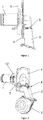
- FIG. 1 shows a burner 1 which is attached to a burner door 4.
- a burner door 4 In the burner door 4 there is an opening, not shown, to which a fuel gas-air feed 3 is attached on the side facing away from the burner 1.
- An ignition electrode 6 is also attached to the burner door 4.
- the connections of the ignition electrode 6 to an automatic ignition (not shown) are located on the side of the fuel gas-air supply 3.
- On the other On the side there are two electrodes of the ignition electrode 6, between which sparks jump over to ignite a fuel gas-air mixture and thus ignite an ignitable mixture.
- An aluminum foam ring 7 is located around the burner 1 on the side of the burner door facing the burner 1.
- aluminum oxide Al 2 O 3 and mullite with the composition Al 2 Al 2 + 2x Si 2-2x O 10- are also suitable. x .
- Figure 2 shows the burner door 4 according to the invention with the aluminum foam ring 7 in perspective with the fan 2 flanged to the fuel gas-air feed 3.
- the burner 1 has a burner flange 12 for assembly.
- the variant shown differs from Figure 2 in that the fuel gas-air supply 3 opens into a mixture hood 5 which, together with the burner door 4, forms a chamber in which the fuel gas-air mixture flows.
- the mixture hood 5 can optionally be made of plastic.
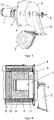
- FIG 4 shows the variant Figure 3 in connection with a heat cell 8 in section.
- the heat cell 8 has a heat exchanger 9, which is arranged coaxially around the burner 1 and forms a combustion chamber 11, and a housing 10 which surrounds the heat exchanger 9.
- a fuel gas-air mixture flows via the fan 2 and the fuel gas-air supply 3 into the burner 1 and is initially ignited outside the burner 1 in the combustion chamber 11.
- a flame forms on the surface of the burner 1.
- the exhaust gases from the flame flow through the heat exchanger 9 and in the process give off thermal energy to a heating circuit, not shown in detail.
- the aluminum foam ring 7 insulates the flow of heat from the combustion chamber 11 through the burner door 4.
- Figure 5 shows the burner door 4 as well as the aluminum foam ring 7 and the burner 1 before assembly.
- the aluminum foam ring 7 has an L-shaped cross-sectional profile, the outer circular area 14 being thick and the inner circular area 15 being thin.
- the inner circular area 15 has an outer diameter which is slightly larger than the outer diameter of the burner flange 12 of the burner 1. In the inner circular area 15 there are also recesses 13.
- FIG 6 shows the mounted burner door 4, the burner 1 being screwed to the burner door 4 via the inner circular area 15 via screws (not shown) through the recesses 13.
- the distance between burner 1 and the outer circular area 14 is also required so that combustion can take place there.
Landscapes
- Engineering & Computer Science (AREA)
- Chemical & Material Sciences (AREA)
- Combustion & Propulsion (AREA)
- Mechanical Engineering (AREA)
- General Engineering & Computer Science (AREA)
- Gas Burners (AREA)
Description
- Die Erfindung bezieht sich auf eine Brennertür einer Wärmezelle einer brennstoffbetriebenen Heizung.
- Bei Brennstoffbetriebenen Heizungen wird ein Brennstoff-Luft-Gemisch in einer Brennkammer erhitzt und die dabei entstehenden Abgase in einem fluidführenden Wärmetauscher abgekühlt. Der Wärmetauscher nimmt auch Strahlungswärme auf. Der Brenner ist dabei zumeist auf einem demontierbaren Bauteil montiert. Diese Baueinheit, wird mit einem Gehäuse, in dem sich der Wärmetauscher befindet, verbunden. Das demontierbare Bauteil, an dem der Brenner montiert ist, wird häufig als Brennertür bezeichnet. Diese Brennertür erhitzt sich durch die Abgase und Wärmestrahlung und muss daher gekühlt oder gedämmt werden, um einerseits Wärmeverluste und andererseits Verletzungen eines Bedieners oder Handwerkers zu vermeiden. Daher befindet sich an der Brennertür um den Brenner herum häufig Wärmedämmungen aus Vermiculit oder Silikatwolle; diese sind zumeist schwer recyclierbar und können zudem bei Wartungsarbeiten leicht beschädigt werden.
- Aus der der Patentanmeldung
US 2012/0000456 A1 ist eine Wärmezelle bekannt, bei der die Brennertür auf der Seite des Brenner mit einem Dämmring aus Keramik wärmegedämmt ist. - Der Brenner selbst ist mit einem Presssitz in den Dämmring eingesetzt.
- Die
EP 0889288 A1 offenbart eine Brennkammer mit einem Metallschaumring. - Aufgabe der Erfindung ist eine Dämmung, welche langlebig und gut zu recyceln ist, bereit zu stellen.
- Diese Aufgabe wird erfindungsgemäß dadurch gelöst, dass an der Brennertür ein metallischer Dämmring aus Aluminiumschaum angebracht ist, und dass sich im dünneren inneren Kreisbereich Aussparungen befinden.
- Vorteilhafte Ausgestaltungen ergeben sich aus den Merkmalen der abhängigen Ansprüche.
- Die Erfindung wird anhand der Figuren näher erläutert. Hierbei zeigen
-
Figur 1 eine erfindungsgemäße Brennertür in der Seitenansicht, -
Figur 2 die erfindungsgemäße Brennertür perspektivisch, -
Figur 3 eine Variante der erfindungsgemäßen Brennertür perspektivisch, -
Figur 4 eine erfindungsgemäße Brennertür in einer Wärmezelle im Schnitt, -
Figur 5 eine erfindungsgemäße Brennertür im Schnitt als Explosionszeichnung sowie -
Figur 6 eine erfindungsgemäße Brennertür im Schnitt mit montiertem Brenner sowie Aluminiumschauring. -
Figur 1 zeigt einen Brenner 1, welcher an einer Brennertür 4 befestigt ist. In der Brennertür 4 befindet sich eine nicht dargestellt Öffnung, an welcher auf der dem Brenner 1 abgewandten Seite eine Brenngas-Luft-Zuführung 3 angebracht ist. An der Brennertür 4 ist ferner eine Zündelektrode 6 angebracht. Auf der Seite der Brenngas-Luft-Zuführung 3 befinden sich die Anschlüsse der Zündelektrode 6 an einen nicht dargestellten Zündautomaten. Auf der anderen Seite befinden sich zwei Elektroden der Zündelektrode 6, zwischen denen zum Zünden eines Brenngas-Luft-Gemischs Funkten überspringen und somit ein zündfähiges Gemisch entzünden. Um den Brenner 1 herum befindet sich auf der dem Brenner 1 zugewandten Seite der Brennertür ein Aluminiumschaumring 7. Nicht erfindungsgemäß eignet sich beispielsweise anstatt Aluminiumschaum auch Aluminiumoxid Al2O3 sowie Mullit der Zusammensetzung Al2Al2+2xSi2-2xO10-x. -
Figur 2 zeigt die erfindungsgemäße Brennertür 4 mit dem Aluminiumschaumring 7 perspektivisch mit an der Brenngas-Luft-Zuführung 3 angeflanschten Gebläse 2. Der Brenner 1 verfügt über einen Brennerflansch 12 für die Montage. - Die in
Figur 3 dargestellte Variante unterscheidet sich vonFigur 2 dadurch, dass die Brenngas-Luft-Zuführung 3 in eine Gemischhaube 5 mündet, welche mit der Brennertür 4 eine Kammer bildet, in welcher Brenngas-Luft-Gemisch strömt. Die Gemischhaube 5 kann optional aus Kunststoff hergestellt sein. -
Figur 4 zeigt die Variante ausFigur 3 in Verbindung mit einer Wärmezelle 8 im Schnitt. Die Wärmezelle 8 verfügt über einen Wärmetauscher 9, der um den Brenner 1 koaxial angeordnet ist und eine Brennkammer 11 bildet sowie ein Gehäuse 10, welches den Wärmetauscher 9 umgibt. - Beim Betrieb strömt ein Brenngas-Luft-Gemisch über das Gebläse 2 und die Brenngas-Luft-Zuführung 3 in den Brenner 1 und wird außerhalb des Brenners 1 in der Brennkammer 11 zunächst gezündet. An der Oberfläche des Brenners 1 bildet sich eine Flamme. Die Abgase der Flamme strömen durch den Wärmetauscher 9 und geben dabei thermische Energie an einen nicht näher dargestellten Heizungskreislauf ab.
- Der Aluminiumschaumring 7 dämmt hierbei den Wärmefluss aus der Brennkammer 11 durch die Brennertür 4.
- Bei der Variante gemäß der
Figuren 3 und 4 wird Wärme, welche durch den Aluminiumschaumring 7 und die Brennertür 4 gelangt, auf das Brenngas-Luft-Gemisch übertragen. -
Figur 5 zeigt die Brennertür 4 sowie den Aluminiumschaumring 7 sowie den Brenner 1 vor der Montage. Der Aluminiumschaumring 7 verfügt über ein L-förmiges Querschnittsprofil, wobei der äußere Kreisbereich 14 dick und der innere Kreisbereich 15 dünn ist. Der innere Kreisbereich 15 hat dabei einen Außendurchmesser, der geringfügig größer ist als der Außendurchmesser der Brennerflansch 12 des Brenners 1. Im inneren Kreisbereich 15 befinden sich ferner Aussparungen 13. -
Figur 6 zeigt die montierte Brennertür 4, wobei der Brenner 1 über den inneren Kreisbereich 15 über nicht dargestellt Schrauben durch die Aussparungen 13 hindurch mit der Brennertür 4 verschraubt ist. Der Abstand zwischen Brenner 1 sowie äußerem Kreisbereich 14 wird auch benötigt, damit dort eine Verbrennung stattfinden kann. -
- 1
- Brenner
- 2
- Gebläse
- 3
- Brenngas-Luft-Zuführung
- 4
- Brennertür
- 5
- Gemischhaube
- 6
- Zündelektrode
- 7
- Aluminiumschaumring
- 8
- Wärmezelle
- 9
- Wärmetauscher
- 10
- Gehäuse
- 11
- Brennkammer
- 12
- Brennerflansch
- 13
- Aussparung
- 14
- äußerer Kreisbereich
- 15
- innerer Kreisbereich
Claims (4)
- Wärmezelle (8) mit einem brennstoffbetriebenen Brenner (1), einem Wärmetauscher (9) zur Übertragung thermischer Energie der Abgase des Brenners (1) auf eine Wärmesenke und einem Gehäuse (10) mit einer Öffnung, welche durch eine demontierbare Brennertür (4) verschließbar ist, wobei auf der einen Seite der Brennertür (4) der Brenner (1) montiert ist und die andere Seite der Brennertür (4) mit einer Brenngas-Luft-Zuführung (3) zur Zuführung eines Brenngas-Luft-Gemisch verbunden ist, wobei sich um den Brenner (1) herum auf der dem Brenner (1) zugewandten Seite der Brennertür (4) ein metallischer Dämmring (7) befindet, wobei der metallische Dämmring (7) ein Aluminiumschaumring (7) ist, wobei der Dämmring (7) über ein L-förmiges Querschnittsprofil verfügt, wobei der äußere Kreisbereich (14) dick und der innere Kreisbereich (15) dünn ist, wobei der Brenner (1) über einen Brennerflansch (12) verfügt und der innere Kreisbereich (15) einen Außendurchmesser hat, der größer ist als der Außendurchmesser des Brennerflanschs (12) des Brenners (1), und wobei sich im inneren Kreisbereich (15) Aussparungen (13) befinden.
- Wärmezelle (8) mit Brennertür (4) nach Anspruch 1, dadurch gekennzeichnet, dass Brenngas-Luft-Zuführung (3) in eine Gemischhaube (5) mündet, welche mit der Brennertür (4) eine Kammer bildet.
- Wärmezelle (8) mit Brennertür (4) nach Anspruch 2, dadurch gekennzeichnet, dass die Gemischhaube (5) aus Kunststoff hergestellt ist.
- Wärmezelle (8) mit Brennertür (4) nach einem der Ansprüche 1 bis 3, dadurch gekennzeichnet, dass der Brennerflansch (12) des Brenners (1) über Schrauben durch die Aussparungen (13) im inneren Kreisbereich (15) des Dämmrings (7) mit der Brennertür (4) verschraubt ist.
Applications Claiming Priority (1)
| Application Number | Priority Date | Filing Date | Title |
|---|---|---|---|
| DE102018102967.5A DE102018102967A1 (de) | 2018-02-09 | 2018-02-09 | Wärmezelle mit metallischem Dämmring |
Publications (2)
| Publication Number | Publication Date |
|---|---|
| EP3524882A1 EP3524882A1 (de) | 2019-08-14 |
| EP3524882B1 true EP3524882B1 (de) | 2020-09-16 |
Family
ID=65324209
Family Applications (1)
| Application Number | Title | Priority Date | Filing Date |
|---|---|---|---|
| EP19155450.0A Active EP3524882B1 (de) | 2018-02-09 | 2019-02-05 | Wärmezelle mit metallischem dämmring |
Country Status (3)
| Country | Link |
|---|---|
| EP (1) | EP3524882B1 (de) |
| DE (1) | DE102018102967A1 (de) |
| ES (1) | ES2836891T3 (de) |
Families Citing this family (1)
| Publication number | Priority date | Publication date | Assignee | Title |
|---|---|---|---|---|
| JP2025117213A (ja) * | 2024-01-30 | 2025-08-12 | リンナイ株式会社 | 熱源機 |
Family Cites Families (4)
| Publication number | Priority date | Publication date | Assignee | Title |
|---|---|---|---|---|
| DE19728397C1 (de) * | 1997-07-03 | 1999-01-14 | Bosch Gmbh Robert | Brenner, insbesondere Gasbrenner |
| FR2854229A1 (fr) * | 2003-04-25 | 2004-10-29 | Realisation Mecaniques Engenee | Echangeur de chaleur a condensation |
| DE102004044332A1 (de) * | 2004-09-09 | 2006-03-30 | Robert Bosch Gmbh | Heizeinrichtung mit einem schallgedämpften Ansaugsystem |
| FR2942866B1 (fr) * | 2009-03-06 | 2012-03-23 | Mer Joseph Le | Porte a bruleur integre pour appareil de chauffage |
-
2018
- 2018-02-09 DE DE102018102967.5A patent/DE102018102967A1/de not_active Withdrawn
-
2019
- 2019-02-05 ES ES19155450T patent/ES2836891T3/es active Active
- 2019-02-05 EP EP19155450.0A patent/EP3524882B1/de active Active
Non-Patent Citations (1)
| Title |
|---|
| None * |
Also Published As
| Publication number | Publication date |
|---|---|
| DE102018102967A1 (de) | 2019-08-14 |
| ES2836891T3 (es) | 2021-06-28 |
| EP3524882A1 (de) | 2019-08-14 |
Similar Documents
| Publication | Publication Date | Title |
|---|---|---|
| EP2871419B1 (de) | Gasturbinenbrennkammer mit Schindel zur Durchführung einer Zündkerze | |
| US10697668B2 (en) | Flue baffle | |
| US10544961B2 (en) | Premix burner internal flue shield | |
| DE4326945A1 (de) | Gaskocheinrichtung mit unter einer durchgehenden Kochfläche aus einem für Wärmestrahlung durchlässigen Material, wie Glaskeramik, angeordneten Gasstrahlungsbrennern | |
| EP0377797B1 (de) | Heizgerät, insbesondere Fahrzeugheizgerät | |
| DE4132236C1 (de) | ||
| EP1484552B1 (de) | Brennkammeranordnung für einen Verdampferbrenner, insbesondere für ein Fahrzeugheizgerät | |
| EP3524882A1 (de) | Wärmezelle mit metallischem dämmring | |
| EP2754958B1 (de) | Strahlheizrohr | |
| EP4047269A1 (de) | Brenner für ein heizgerät und seine anordnung im heizgerät | |
| EP1552218B1 (de) | Brenner, insbesondere venturibrenner, mit einem brennkammerrohr | |
| DE2839460C2 (de) | ||
| EP2051006A1 (de) | Heizgerät | |
| DE10041472C1 (de) | Gasstrahlungsbrenner | |
| EP1780469B1 (de) | Gaskochfeld | |
| DE2721663C3 (de) | Dichtung zur Abdichtung des Strahlrohres | |
| AT248009B (de) | Als Luftvorwärmer ausgebildete Feuertüre | |
| EP4209709B1 (de) | Heizgerät und schalldämpfer | |
| EP0137362A2 (de) | Grossformatiges Strahlungselement für Industrieöfen | |
| EP1482242B1 (de) | Brennkammeranordnung | |
| EP3376112B1 (de) | Geschlossene feuerstätte | |
| DE4301780A1 (de) | Blende für Öl- oder Gasbrenner | |
| DE202020101167U1 (de) | Rekuperatorbrenner | |
| DE2053805A1 (de) | Rekuperativ-Brenner | |
| DE1246151B (de) | Strahlheizrohr mit in einem Rohrschenkel angeordneten Waermetauscher |
Legal Events
| Date | Code | Title | Description |
|---|---|---|---|
| PUAI | Public reference made under article 153(3) epc to a published international application that has entered the european phase |
Free format text: ORIGINAL CODE: 0009012 |
|
| STAA | Information on the status of an ep patent application or granted ep patent |
Free format text: STATUS: THE APPLICATION HAS BEEN PUBLISHED |
|
| AK | Designated contracting states |
Kind code of ref document: A1 Designated state(s): AL AT BE BG CH CY CZ DE DK EE ES FI FR GB GR HR HU IE IS IT LI LT LU LV MC MK MT NL NO PL PT RO RS SE SI SK SM TR |
|
| AX | Request for extension of the european patent |
Extension state: BA ME |
|
| STAA | Information on the status of an ep patent application or granted ep patent |
Free format text: STATUS: REQUEST FOR EXAMINATION WAS MADE |
|
| 17P | Request for examination filed |
Effective date: 20200214 |
|
| RBV | Designated contracting states (corrected) |
Designated state(s): AL AT BE BG CH CY CZ DE DK EE ES FI FR GB GR HR HU IE IS IT LI LT LU LV MC MK MT NL NO PL PT RO RS SE SI SK SM TR |
|
| RIC1 | Information provided on ipc code assigned before grant |
Ipc: F23M 7/02 20060101ALI20200310BHEP Ipc: F24H 1/00 20060101ALI20200310BHEP Ipc: F24H 9/02 20060101ALI20200310BHEP Ipc: F23M 7/00 20060101AFI20200310BHEP Ipc: F24H 1/14 20060101ALI20200310BHEP Ipc: F23M 7/04 20060101ALI20200310BHEP Ipc: F24H 1/43 20060101ALI20200310BHEP |
|
| GRAP | Despatch of communication of intention to grant a patent |
Free format text: ORIGINAL CODE: EPIDOSNIGR1 |
|
| STAA | Information on the status of an ep patent application or granted ep patent |
Free format text: STATUS: GRANT OF PATENT IS INTENDED |
|
| INTG | Intention to grant announced |
Effective date: 20200519 |
|
| GRAS | Grant fee paid |
Free format text: ORIGINAL CODE: EPIDOSNIGR3 |
|
| GRAA | (expected) grant |
Free format text: ORIGINAL CODE: 0009210 |
|
| STAA | Information on the status of an ep patent application or granted ep patent |
Free format text: STATUS: THE PATENT HAS BEEN GRANTED |
|
| AK | Designated contracting states |
Kind code of ref document: B1 Designated state(s): AL AT BE BG CH CY CZ DE DK EE ES FI FR GB GR HR HU IE IS IT LI LT LU LV MC MK MT NL NO PL PT RO RS SE SI SK SM TR |
|
| REG | Reference to a national code |
Ref country code: GB Ref legal event code: FG4D Free format text: NOT ENGLISH |
|
| REG | Reference to a national code |
Ref country code: CH Ref legal event code: EP |
|
| REG | Reference to a national code |
Ref country code: DE Ref legal event code: R096 Ref document number: 502019000211 Country of ref document: DE |
|
| REG | Reference to a national code |
Ref country code: IE Ref legal event code: FG4D Free format text: LANGUAGE OF EP DOCUMENT: GERMAN |
|
| REG | Reference to a national code |
Ref country code: AT Ref legal event code: REF Ref document number: 1314487 Country of ref document: AT Kind code of ref document: T Effective date: 20201015 |
|
| REG | Reference to a national code |
Ref country code: SK Ref legal event code: T3 Ref document number: E 35936 Country of ref document: SK |
|
| PG25 | Lapsed in a contracting state [announced via postgrant information from national office to epo] |
Ref country code: HR Free format text: LAPSE BECAUSE OF FAILURE TO SUBMIT A TRANSLATION OF THE DESCRIPTION OR TO PAY THE FEE WITHIN THE PRESCRIBED TIME-LIMIT Effective date: 20200916 Ref country code: BG Free format text: LAPSE BECAUSE OF FAILURE TO SUBMIT A TRANSLATION OF THE DESCRIPTION OR TO PAY THE FEE WITHIN THE PRESCRIBED TIME-LIMIT Effective date: 20201216 Ref country code: SE Free format text: LAPSE BECAUSE OF FAILURE TO SUBMIT A TRANSLATION OF THE DESCRIPTION OR TO PAY THE FEE WITHIN THE PRESCRIBED TIME-LIMIT Effective date: 20200916 Ref country code: NO Free format text: LAPSE BECAUSE OF FAILURE TO SUBMIT A TRANSLATION OF THE DESCRIPTION OR TO PAY THE FEE WITHIN THE PRESCRIBED TIME-LIMIT Effective date: 20201216 Ref country code: FI Free format text: LAPSE BECAUSE OF FAILURE TO SUBMIT A TRANSLATION OF THE DESCRIPTION OR TO PAY THE FEE WITHIN THE PRESCRIBED TIME-LIMIT Effective date: 20200916 Ref country code: GR Free format text: LAPSE BECAUSE OF FAILURE TO SUBMIT A TRANSLATION OF THE DESCRIPTION OR TO PAY THE FEE WITHIN THE PRESCRIBED TIME-LIMIT Effective date: 20201217 |
|
| PG25 | Lapsed in a contracting state [announced via postgrant information from national office to epo] |
Ref country code: RS Free format text: LAPSE BECAUSE OF FAILURE TO SUBMIT A TRANSLATION OF THE DESCRIPTION OR TO PAY THE FEE WITHIN THE PRESCRIBED TIME-LIMIT Effective date: 20200916 Ref country code: LV Free format text: LAPSE BECAUSE OF FAILURE TO SUBMIT A TRANSLATION OF THE DESCRIPTION OR TO PAY THE FEE WITHIN THE PRESCRIBED TIME-LIMIT Effective date: 20200916 |
|
| REG | Reference to a national code |
Ref country code: LT Ref legal event code: MG4D |
|
| PG25 | Lapsed in a contracting state [announced via postgrant information from national office to epo] |
Ref country code: LT Free format text: LAPSE BECAUSE OF FAILURE TO SUBMIT A TRANSLATION OF THE DESCRIPTION OR TO PAY THE FEE WITHIN THE PRESCRIBED TIME-LIMIT Effective date: 20200916 Ref country code: PT Free format text: LAPSE BECAUSE OF FAILURE TO SUBMIT A TRANSLATION OF THE DESCRIPTION OR TO PAY THE FEE WITHIN THE PRESCRIBED TIME-LIMIT Effective date: 20210118 Ref country code: RO Free format text: LAPSE BECAUSE OF FAILURE TO SUBMIT A TRANSLATION OF THE DESCRIPTION OR TO PAY THE FEE WITHIN THE PRESCRIBED TIME-LIMIT Effective date: 20200916 Ref country code: EE Free format text: LAPSE BECAUSE OF FAILURE TO SUBMIT A TRANSLATION OF THE DESCRIPTION OR TO PAY THE FEE WITHIN THE PRESCRIBED TIME-LIMIT Effective date: 20200916 Ref country code: SM Free format text: LAPSE BECAUSE OF FAILURE TO SUBMIT A TRANSLATION OF THE DESCRIPTION OR TO PAY THE FEE WITHIN THE PRESCRIBED TIME-LIMIT Effective date: 20200916 |
|
| PG25 | Lapsed in a contracting state [announced via postgrant information from national office to epo] |
Ref country code: AL Free format text: LAPSE BECAUSE OF FAILURE TO SUBMIT A TRANSLATION OF THE DESCRIPTION OR TO PAY THE FEE WITHIN THE PRESCRIBED TIME-LIMIT Effective date: 20200916 Ref country code: IS Free format text: LAPSE BECAUSE OF FAILURE TO SUBMIT A TRANSLATION OF THE DESCRIPTION OR TO PAY THE FEE WITHIN THE PRESCRIBED TIME-LIMIT Effective date: 20210116 Ref country code: PL Free format text: LAPSE BECAUSE OF FAILURE TO SUBMIT A TRANSLATION OF THE DESCRIPTION OR TO PAY THE FEE WITHIN THE PRESCRIBED TIME-LIMIT Effective date: 20200916 |
|
| REG | Reference to a national code |
Ref country code: DE Ref legal event code: R097 Ref document number: 502019000211 Country of ref document: DE |
|
| REG | Reference to a national code |
Ref country code: ES Ref legal event code: FG2A Ref document number: 2836891 Country of ref document: ES Kind code of ref document: T3 Effective date: 20210628 |
|
| PLBE | No opposition filed within time limit |
Free format text: ORIGINAL CODE: 0009261 |
|
| STAA | Information on the status of an ep patent application or granted ep patent |
Free format text: STATUS: NO OPPOSITION FILED WITHIN TIME LIMIT |
|
| 26N | No opposition filed |
Effective date: 20210617 |
|
| PG25 | Lapsed in a contracting state [announced via postgrant information from national office to epo] |
Ref country code: SI Free format text: LAPSE BECAUSE OF FAILURE TO SUBMIT A TRANSLATION OF THE DESCRIPTION OR TO PAY THE FEE WITHIN THE PRESCRIBED TIME-LIMIT Effective date: 20200916 Ref country code: DK Free format text: LAPSE BECAUSE OF FAILURE TO SUBMIT A TRANSLATION OF THE DESCRIPTION OR TO PAY THE FEE WITHIN THE PRESCRIBED TIME-LIMIT Effective date: 20200916 |
|
| PG25 | Lapsed in a contracting state [announced via postgrant information from national office to epo] |
Ref country code: MC Free format text: LAPSE BECAUSE OF FAILURE TO SUBMIT A TRANSLATION OF THE DESCRIPTION OR TO PAY THE FEE WITHIN THE PRESCRIBED TIME-LIMIT Effective date: 20200916 |
|
| REG | Reference to a national code |
Ref country code: NL Ref legal event code: FP |
|
| PG25 | Lapsed in a contracting state [announced via postgrant information from national office to epo] |
Ref country code: LU Free format text: LAPSE BECAUSE OF NON-PAYMENT OF DUE FEES Effective date: 20210205 |
|
| PG25 | Lapsed in a contracting state [announced via postgrant information from national office to epo] |
Ref country code: IE Free format text: LAPSE BECAUSE OF NON-PAYMENT OF DUE FEES Effective date: 20210205 |
|
| PG25 | Lapsed in a contracting state [announced via postgrant information from national office to epo] |
Ref country code: CY Free format text: LAPSE BECAUSE OF FAILURE TO SUBMIT A TRANSLATION OF THE DESCRIPTION OR TO PAY THE FEE WITHIN THE PRESCRIBED TIME-LIMIT Effective date: 20200916 |
|
| PG25 | Lapsed in a contracting state [announced via postgrant information from national office to epo] |
Ref country code: HU Free format text: LAPSE BECAUSE OF FAILURE TO SUBMIT A TRANSLATION OF THE DESCRIPTION OR TO PAY THE FEE WITHIN THE PRESCRIBED TIME-LIMIT; INVALID AB INITIO Effective date: 20190205 |
|
| PGFP | Annual fee paid to national office [announced via postgrant information from national office to epo] |
Ref country code: AT Payment date: 20240131 Year of fee payment: 6 |
|
| PG25 | Lapsed in a contracting state [announced via postgrant information from national office to epo] |
Ref country code: MK Free format text: LAPSE BECAUSE OF FAILURE TO SUBMIT A TRANSLATION OF THE DESCRIPTION OR TO PAY THE FEE WITHIN THE PRESCRIBED TIME-LIMIT Effective date: 20200916 |
|
| PGFP | Annual fee paid to national office [announced via postgrant information from national office to epo] |
Ref country code: CZ Payment date: 20240122 Year of fee payment: 6 Ref country code: CH Payment date: 20240301 Year of fee payment: 6 |
|
| PG25 | Lapsed in a contracting state [announced via postgrant information from national office to epo] |
Ref country code: MT Free format text: LAPSE BECAUSE OF FAILURE TO SUBMIT A TRANSLATION OF THE DESCRIPTION OR TO PAY THE FEE WITHIN THE PRESCRIBED TIME-LIMIT Effective date: 20200916 |
|
| PGFP | Annual fee paid to national office [announced via postgrant information from national office to epo] |
Ref country code: NL Payment date: 20250127 Year of fee payment: 7 |
|
| PGFP | Annual fee paid to national office [announced via postgrant information from national office to epo] |
Ref country code: DE Payment date: 20250127 Year of fee payment: 7 |
|
| PGFP | Annual fee paid to national office [announced via postgrant information from national office to epo] |
Ref country code: ES Payment date: 20250303 Year of fee payment: 7 |
|
| PGFP | Annual fee paid to national office [announced via postgrant information from national office to epo] |
Ref country code: BE Payment date: 20250127 Year of fee payment: 7 |
|
| PGFP | Annual fee paid to national office [announced via postgrant information from national office to epo] |
Ref country code: FR Payment date: 20250218 Year of fee payment: 7 |
|
| PGFP | Annual fee paid to national office [announced via postgrant information from national office to epo] |
Ref country code: IT Payment date: 20250226 Year of fee payment: 7 Ref country code: SK Payment date: 20250203 Year of fee payment: 7 Ref country code: GB Payment date: 20250128 Year of fee payment: 7 |
|
| PGFP | Annual fee paid to national office [announced via postgrant information from national office to epo] |
Ref country code: TR Payment date: 20250129 Year of fee payment: 7 |
|
| REG | Reference to a national code |
Ref country code: CH Ref legal event code: PL |
|
| REG | Reference to a national code |
Ref country code: AT Ref legal event code: MM01 Ref document number: 1314487 Country of ref document: AT Kind code of ref document: T Effective date: 20250205 |
|
| PG25 | Lapsed in a contracting state [announced via postgrant information from national office to epo] |
Ref country code: AT Free format text: LAPSE BECAUSE OF NON-PAYMENT OF DUE FEES Effective date: 20250205 |
|
| PG25 | Lapsed in a contracting state [announced via postgrant information from national office to epo] |
Ref country code: CH Free format text: LAPSE BECAUSE OF NON-PAYMENT OF DUE FEES Effective date: 20250228 |
|
| PG25 | Lapsed in a contracting state [announced via postgrant information from national office to epo] |
Ref country code: CZ Free format text: LAPSE BECAUSE OF NON-PAYMENT OF DUE FEES Effective date: 20250205 |