EP3524914A1 - Thermodynamisches heizgerät mit optimiertem mikrokanalkondensator für eine minimale beladung mit kühlflüssigkeit - Google Patents
Thermodynamisches heizgerät mit optimiertem mikrokanalkondensator für eine minimale beladung mit kühlflüssigkeit Download PDFInfo
- Publication number
- EP3524914A1 EP3524914A1 EP19305146.3A EP19305146A EP3524914A1 EP 3524914 A1 EP3524914 A1 EP 3524914A1 EP 19305146 A EP19305146 A EP 19305146A EP 3524914 A1 EP3524914 A1 EP 3524914A1
- Authority
- EP
- European Patent Office
- Prior art keywords
- collector
- bar
- collectors
- cross
- channel
- Prior art date
- Legal status (The legal status is an assumption and is not a legal conclusion. Google has not performed a legal analysis and makes no representation as to the accuracy of the status listed.)
- Granted
Links
Images


Classifications
-
- F—MECHANICAL ENGINEERING; LIGHTING; HEATING; WEAPONS; BLASTING
- F28—HEAT EXCHANGE IN GENERAL
- F28D—HEAT-EXCHANGE APPARATUS, NOT PROVIDED FOR IN ANOTHER SUBCLASS, IN WHICH THE HEAT-EXCHANGE MEDIA DO NOT COME INTO DIRECT CONTACT
- F28D20/00—Heat storage plants or apparatus in general; Regenerative heat-exchange apparatus not covered by groups F28D17/00 or F28D19/00
- F28D20/0034—Heat storage plants or apparatus in general; Regenerative heat-exchange apparatus not covered by groups F28D17/00 or F28D19/00 using liquid heat storage material
-
- F—MECHANICAL ENGINEERING; LIGHTING; HEATING; WEAPONS; BLASTING
- F28—HEAT EXCHANGE IN GENERAL
- F28D—HEAT-EXCHANGE APPARATUS, NOT PROVIDED FOR IN ANOTHER SUBCLASS, IN WHICH THE HEAT-EXCHANGE MEDIA DO NOT COME INTO DIRECT CONTACT
- F28D1/00—Heat-exchange apparatus having stationary conduit assemblies for one heat-exchange medium only, the media being in contact with different sides of the conduit wall, in which the other heat-exchange medium is a large body of fluid, e.g. domestic or motor car radiators
- F28D1/02—Heat-exchange apparatus having stationary conduit assemblies for one heat-exchange medium only, the media being in contact with different sides of the conduit wall, in which the other heat-exchange medium is a large body of fluid, e.g. domestic or motor car radiators with heat-exchange conduits immersed in the body of fluid
- F28D1/04—Heat-exchange apparatus having stationary conduit assemblies for one heat-exchange medium only, the media being in contact with different sides of the conduit wall, in which the other heat-exchange medium is a large body of fluid, e.g. domestic or motor car radiators with heat-exchange conduits immersed in the body of fluid with tubular conduits
- F28D1/047—Heat-exchange apparatus having stationary conduit assemblies for one heat-exchange medium only, the media being in contact with different sides of the conduit wall, in which the other heat-exchange medium is a large body of fluid, e.g. domestic or motor car radiators with heat-exchange conduits immersed in the body of fluid with tubular conduits the conduits being bent, e.g. in a serpentine or zig-zag
- F28D1/0471—Heat-exchange apparatus having stationary conduit assemblies for one heat-exchange medium only, the media being in contact with different sides of the conduit wall, in which the other heat-exchange medium is a large body of fluid, e.g. domestic or motor car radiators with heat-exchange conduits immersed in the body of fluid with tubular conduits the conduits being bent, e.g. in a serpentine or zig-zag the conduits having a non-circular cross-section
-
- F—MECHANICAL ENGINEERING; LIGHTING; HEATING; WEAPONS; BLASTING
- F28—HEAT EXCHANGE IN GENERAL
- F28D—HEAT-EXCHANGE APPARATUS, NOT PROVIDED FOR IN ANOTHER SUBCLASS, IN WHICH THE HEAT-EXCHANGE MEDIA DO NOT COME INTO DIRECT CONTACT
- F28D1/00—Heat-exchange apparatus having stationary conduit assemblies for one heat-exchange medium only, the media being in contact with different sides of the conduit wall, in which the other heat-exchange medium is a large body of fluid, e.g. domestic or motor car radiators
- F28D1/06—Heat-exchange apparatus having stationary conduit assemblies for one heat-exchange medium only, the media being in contact with different sides of the conduit wall, in which the other heat-exchange medium is a large body of fluid, e.g. domestic or motor car radiators with the heat-exchange conduits forming part of, or being attached to, the tank containing the body of fluid
-
- F—MECHANICAL ENGINEERING; LIGHTING; HEATING; WEAPONS; BLASTING
- F28—HEAT EXCHANGE IN GENERAL
- F28F—DETAILS OF HEAT-EXCHANGE AND HEAT-TRANSFER APPARATUS, OF GENERAL APPLICATION
- F28F1/00—Tubular elements; Assemblies of tubular elements
- F28F1/02—Tubular elements of cross-section which is non-circular
- F28F1/022—Tubular elements of cross-section which is non-circular with multiple channels
-
- F—MECHANICAL ENGINEERING; LIGHTING; HEATING; WEAPONS; BLASTING
- F28—HEAT EXCHANGE IN GENERAL
- F28F—DETAILS OF HEAT-EXCHANGE AND HEAT-TRANSFER APPARATUS, OF GENERAL APPLICATION
- F28F9/00—Casings; Header boxes; Auxiliary supports for elements; Auxiliary members within casings
- F28F9/001—Casings in the form of plate-like arrangements; Frames enclosing a heat exchange core
- F28F9/002—Casings in the form of plate-like arrangements; Frames enclosing a heat exchange core with fastening means for other structures
-
- F—MECHANICAL ENGINEERING; LIGHTING; HEATING; WEAPONS; BLASTING
- F28—HEAT EXCHANGE IN GENERAL
- F28D—HEAT-EXCHANGE APPARATUS, NOT PROVIDED FOR IN ANOTHER SUBCLASS, IN WHICH THE HEAT-EXCHANGE MEDIA DO NOT COME INTO DIRECT CONTACT
- F28D1/00—Heat-exchange apparatus having stationary conduit assemblies for one heat-exchange medium only, the media being in contact with different sides of the conduit wall, in which the other heat-exchange medium is a large body of fluid, e.g. domestic or motor car radiators
- F28D1/02—Heat-exchange apparatus having stationary conduit assemblies for one heat-exchange medium only, the media being in contact with different sides of the conduit wall, in which the other heat-exchange medium is a large body of fluid, e.g. domestic or motor car radiators with heat-exchange conduits immersed in the body of fluid
- F28D2001/0253—Particular components
- F28D2001/026—Cores
- F28D2001/0273—Cores having special shape, e.g. curved, annular
-
- F—MECHANICAL ENGINEERING; LIGHTING; HEATING; WEAPONS; BLASTING
- F28—HEAT EXCHANGE IN GENERAL
- F28F—DETAILS OF HEAT-EXCHANGE AND HEAT-TRANSFER APPARATUS, OF GENERAL APPLICATION
- F28F2275/00—Fastening; Joining
- F28F2275/08—Fastening; Joining by clamping or clipping
-
- Y—GENERAL TAGGING OF NEW TECHNOLOGICAL DEVELOPMENTS; GENERAL TAGGING OF CROSS-SECTIONAL TECHNOLOGIES SPANNING OVER SEVERAL SECTIONS OF THE IPC; TECHNICAL SUBJECTS COVERED BY FORMER USPC CROSS-REFERENCE ART COLLECTIONS [XRACs] AND DIGESTS
- Y02—TECHNOLOGIES OR APPLICATIONS FOR MITIGATION OR ADAPTATION AGAINST CLIMATE CHANGE
- Y02E—REDUCTION OF GREENHOUSE GAS [GHG] EMISSIONS, RELATED TO ENERGY GENERATION, TRANSMISSION OR DISTRIBUTION
- Y02E60/00—Enabling technologies; Technologies with a potential or indirect contribution to GHG emissions mitigation
- Y02E60/14—Thermal energy storage
Definitions
- the present invention relates to a thermodynamic heating apparatus comprising a condenser wound around a tank for containing liquid.
- Thermodynamic heating apparatus for heating a tank filled with liquid, for example water.
- These devices include a heat pump system that includes a refrigerant circuit containing a refrigerant or refrigerant.
- the refrigerant circulates in this circuit through the various components of the circuit (compressor, condenser, expander and evaporator) and following the conventional thermodynamic cycle: compression, condensation, expansion and evaporation.
- This refrigerant is a harmful element for the environment and is subject to a European regulation (F-gas) which aims to reduce the amount of harmful refrigerant.
- F-gas European regulation
- thermodynamic water heaters The coiled tubing technology, which was first used on thermodynamic water heaters, has a large internal volume and therefore a refrigerant charge that is too high.
- the micro-channel belt takes advantage of the coiled tube (double wall and scaling reduction) and focuses on minimizing the internal volume of the exchanger for the same exchange surface given the use of mini or micro-channel.
- the reduced passage section of a mini / micro-channel tube or strip induces a large linear pressure drop which, as a result, requires a small mini / micro channel length to remain in the allowable pressure drops of the exchanger.
- the tubes or mini / micro-channel strips are arranged in parallel and the different tubes or strips are interconnected by a collector tube which allows the distribution of the fluid in the different channels.
- the assembly process and manifold typology is derived from the automotive industry.
- This technology has significantly reduced the refrigerant charge.
- thermodynamic heating apparatus according to claim 1.
- the general D-shape of the cross-section of the collectors makes it possible to reduce their internal volume which is not useful for the heat transfer in these collectors with respect to the volume of cross-section collectors.
- circular whose diameter corresponds to the length of the bar (for example rectilinear) D.
- the domed portion of the general shape of D may be semicircular or have a generally rounded shape that does not necessarily correspond to the curvature of a circle.
- the curved portion In general, the curved portion, more or less flattened and therefore more or less curved, allows the collectors to maintain a mechanical resistance to deformation sufficient to withstand the pressure exerted by the refrigerant, where a shape at right angles ( eg rectangle) would not achieve this goal.
- the part of the collectors which is intended to be in contact with the liquid tank to be heated is the one which corresponds, in a cross-sectional view, to the bar of the D (the bar of the D is generally substantially rectilinear, c ' that is to say that this side of the D is generally substantially flat, but the bar of the D can alternatively be slightly curved with the concavity turned towards the tank to fit more closely the convexity of the external face of the tank) of the cross-section collectors.
- the thermal contact and therefore the heat exchange with the wall of the tank is thus improved (the thermal resistance between the collector and the wall is reduced), which greatly reduces the heat-inactivated areas of the collectors. Due to this bar contact of the substantially flat D - tank (or in any case which approaches a plane contact), the mechanical tensions can be reduced on the strips, especially at the point of their connection with the collectors.
- the improved contact of the collectors with the wall of the tank also reduces the voltages or mechanical stresses to which are subjected in particular the parts of the condenser located at the junction between the channels and collectors.
- Such a D shape does not generally induce too high pressure drops.
- the D-shape of the collector makes it possible to guarantee the integrity of the condenser during its deformation by bending to wind around the tank and its clamping thereon, avoiding mechanical stresses.
- Each collector generally comprises one or more longitudinal compartments separated from one another by a transverse partition which extends along the entire cross section of the collector.
- a or a plurality of channel strips are arranged to connect a first compartment which is adjacent a first end of a first manifold to a second compartment which is adjacent a first end of the second manifold facing.
- the second compartment has a longitudinal dimension greater than that of the first compartment so as to allow one or more other channel strips to connect the second compartment of the second collector to a third compartment of the first collector.
- the first and third compartments of the first manifold are transversely separated from one another by an inner wall. The foregoing diagram may be repeated several times passing from one collector to the other until reaching the respective second ends of the two collectors.
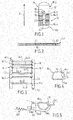
- a tank 10 of a thermodynamic heater contains liquid, for example water, which is intended to be heated by a cooling circuit of a heat pump (PAC) of the apparatus.
- the device is a water heater.
- the tank 10 filled with water extends along a longitudinal dimension which, here, is taken along the vertical axis to the extent that the tank is arranged vertically for its installation and operation.
- the tank may alternatively be arranged horizontally or inclined between the vertical position and the horizontal position according to other possible configurations of installation.
- the vessel comprises a wall 12 which is here generally cylindrical and is closed at its two opposite ends by two substantially hemispherical bottoms or caps 14 and 16, giving the entire vessel a generally substantially cylindrical shape.
- the water heater also comprises, not shown, a heat pump system which comprises a refrigerant circuit a part of which is wound around the tank 10 and which contains a refrigerant for example r134a.
- Part 14 of the refrigerant circuit which is wound around the tank generally forms the condenser of the circuit. It comprises a plurality of coils 14.1, 14.2, ..., 14.n parallel to each other (arranged at different sides) in each of which the refrigerant circulates and which are in thermal contact with the external face of the wall 12 of tank.
- Each winding corresponds to a part of the condenser which extends here over almost the entire circumference of the vessel: the two opposite ends of each winding are each connected to a collector perpendicular to the windings and the two parallel collectors 16, 18, spaced apart from each other are attached together by fasteners 20, 22, 24 which each extend over an angular portion (of the order of a few degrees) of the circumference of the vessel.
- Fastening devices that are conventional are distributed along the longitudinal dimension of the collectors (here the height). According to a variant not shown a single attachment device can be used and it extends over almost all of the longitudinal dimension of the manifolds to distribute longitudinally the clamping force.
- each winding 14i here takes the form of a band which comprises a plurality of fluid channels Ci adjacent and parallel to each other. This is for example mini or micro-channels whose hydraulic diameter can be of the order of 0.4 to 1 millimeters.
- the assembly formed of parallel strips between them and the two collectors to which each strip is connected by its two opposite ends is able to be bent around an axis parallel to the axis of the collectors so as to adopt a generally cylindrical shape.
- This axis corresponds to the axis of the cylindrical vessel when the assembly is shaped around the tank for its introduction.
- Each band thus wraps around the tank over almost the entire circumference of the tank, in the manner of an annular belt as illustrated in FIG. figure 1 .
- the collectors 16, 18 distribute the refrigerant to the different bands. These collectors are each connected to a part (component) of the PAC system.
- the bands are identical but may be different (at least for some) in a variant.
- the figure 3 illustrates the set of strips and collectors forming the condenser in a manner deployed in a plane to facilitate understanding of the operation.
- the configuration of the condenser which is illustrated has been simplified for convenience. However, the number of strips, their distribution between the different internal areas (or compartments) of the collectors and different details of implementation may vary.
- the internal volume of the two collectors 16, 18 is reduced over at least a portion of its longitudinal dimension so as to separate in two zones 16.1 and 16.2, 18.1 and 18.2 the internal volume of each collector on said at least one portion .
- the refrigerant arrives at the top (F1) in a first compartment 16.1 of the collector 16 where it is distributed in the strips 14.1, 14.2, 14.3, spring of each of them at their opposite end in a first compartment 18.1 of the collector 18 that it runs longitudinally before distributing in the bands 14.4, 14.5 and out of each of them at their opposite end in a second compartment 16.2 of the collector 16.
- the fluid runs longitudinally this compartment, is then distributed in Band 14.6, which is apparent from opposite end to open into a second compartment 18.2 of the collector 18 and out of the bottom (F2).
- the two collectors 16, 18 are here respectively divided into two compartments or internal areas by a separating partition c1, c2. More compartments can be considered in other configurations.
- the channel strips have opposite ends which open respectively in the corresponding areas vis-à-vis the two collectors.
- the figure 4 represents the collector 16 in cross section (the section is identical for the two collectors) according to one embodiment of the invention.
- the collector 16 has in cross section a general shape of D which extends over the entire longitudinal dimension of the collector.
- the general shape of D comprises a portion 16a forming the bar of D (part not necessarily rectilinear but can be concave to adapt to the convexity of the outer face of the wall of the tank) and a convex portion 16b which extends from one end of the D-bar to the opposite end of said bar.
- the curved portion here has a generally semi-circular shape although it can adopt other types of convexities, or even a flattened shape with only two lateral connections more or less inclined and / or curved to join the bar D.
- the volume internal reduction is reduced, which reduces the volume of refrigerant in the collectors and therefore in the condenser.
- the internal volume reduction of a collector is of the order of 45% with respect to a collector of circular section of the same diameter.
- the bar 16a of the D is intended to be arranged vis-à-vis the wall of the tank (the convex face 16b turning the back to the tank) and against this, this which allows a positioning of the collector as close as possible to the wall (most in contact with the wall), therefore a lower thermal resistance between the two and thus a better heat transfer. As a result, a better contact of the strips with the wall of the vessel is obtained and thus a favored thermal exchange.
- the band 14i (the following applies to all the bands 141 to 14n) has an end 14i1 which penetrates inside the collector, near one of the two opposite ends of the bar 16a D. It in is likewise at the opposite end (not shown) of the band 14i with the collector 18.
- the end 14i1 contains the ends of all the channels Ci ( fig.2 ) forming the band and which open into the internal volume of the collector.
- the penetrating ends of the strip 14i and therefore of each channel thereof are substantially parallel to the bar D. This arrangement facilitates the embedding of the strips in the collectors.
- the figure 5 illustrates in cross section a possible fastening device attached to the manifold 18. This device is also intended to be attached to the collector 16, as shown in FIG. figure 7 .
- the fastening device which corresponds to the devices 20, 22 and 24 comprises a part 30 forming a support and attachment reinforcement which has a hollow portion 30a intended to interface with the curved portion 18b of the collector and to be fixed there for example by brazing.
- the part 30 comprises a free opposite portion 30b pierced with a through hole 30c intended to receive one of the two opposite ends of a tensioner or spring 32 (clamping piece) as schematically illustrated on the figure 5 .
- FIGs 6a and 6b are comparative views showing the improved positioning of the collectors according to one embodiment of the invention ( figure 6a ) with respect to the prior art ( figure 6b ).
- the collectors 16, 18 of generally D-shaped cross-section are positioned closer to the wall 12 of the tank thanks to the bar D coming into contact with this wall over a large part of its length (note that the bar D can alternatively be concave to better match the local convexity of the wall of the tank).
- the portions b1 and b2 of the channel strips that are close to the ends of these strips can not be in contact with the wall 12 because of this point contact / linear collector tube-tank wall, thus creating an inactive zone for thermal transfer.
- Such a configuration therefore penalizes the heat transfer between the exchanger and the wall of the tank and therefore with the liquid to be heated.
- the portions b1 and b2 of the channel strips are subjected to high torsion forces due to the spring fastening devices which tend to bring one of the other the two collectors.
- collectors 16 and 18 of the figure 6a reduces the torsional forces applied to the collector-channel band connections.
- the figure 7 illustrates in perspective the entire condenser formed strips 14.1 to 14.n fluidly connected to the collectors 16, 18 which are attached to each other by the fastening devices 20, 22 and 24. In this figure, some devices are not complete: only the support and reinforcement part 30 is present on the collectors waiting for reception of an additional clamping piece 32.
- the collector 40 (generally D-shaped in cross section with the bar 40a and the curved portion or face 40b) has an internal partition 42 which separates into two internal zones z1, z2, the semicircular internal volume of the collector.
- the internal partition 42 extends over at least a portion of the longitudinal dimension of the manifold, parallel to the bar 40a D.
- the other collector may have a similar configuration.
- each band and thus of each channel are arranged between the bar 40a of the D and the internal partition 42 so that one of the zones, z1, is delimited by the bar of the D and the partition.
- the other zone z2 is, for its part, delimited by the partition 42 and a portion of the curved portion 40b of the D.
- the additional internal partition can be made simply of aluminum by extrusion.
- the internal volume of at least one of the two manifolds is reduced over a portion of its longitudinal dimension (length) that includes one of the two opposite ends of the manifold.
- the reduction in volume imposed on the refrigerant fluid occurs on a portion of length of one or both collectors and thus leaves less room for fluid in said portion.
- This may be useful in the zone or areas of the condenser where the refrigerant is in the liquid or mixed phase and therefore where the pressure losses are the lowest.
- the two collectors 50 and 52 are both divided into two compartments 50.1 and 50.2, 52.1 and 52.2 (as on the figure 3 ) and the internal volume of the second compartment of each manifold 50.2 and 52.2 is reduced. Note that a different number of internal compartments may be considered and the internal volume reduction applies to the end compartment of each collector. Furthermore, a single compartment from one end to the other of the collector may alternatively be considered.
- each manifold 50, 52 is thus reduced for example by the presence of an insert 54, 56 which is disposed inside the corresponding manifold, here in the second compartment 50.2, 52.2.
- the insert for example 56, is disposed against a concave portion of the curved portion 52b of the D so as to leave the area adjacent to the bar 52a of the D in a cross-sectional view of the collector-channel arrangement ( figure 9b ).
- the insert acts as a shutter that occupies a portion of the internal volume of the collector to reduce the volume left free for the fluid.
- the inserts have lengths and sections adapted to the compartments where they are put in place.
- the insert 54 is thus longer than the insert 56.
- the Figure 10 illustrates an alternative embodiment of a general form of D of a collector, denoted 60, a condenser (connected to a channel strip 14i as for the other embodiments) for thermodynamic heater tank.
- the general shape of the D is flatter than in the previously described figures in such a way that the bar of the D 60a is substantially parallel to a substantially rectilinear portion 60b of the portion
- the bar D 60a and said portion 60b are connected together by two portions or lateral sides 60c and 60d more or less inclined towards one another.
- the two portions or lateral flanks 60c, 60d each join the substantially rectilinear portion 60b of the curved portion of the D along a curved connection 60c1, 60d1 so that the overall internal shape of the D withstands the internal fluid pressure .
Landscapes
- Engineering & Computer Science (AREA)
- Physics & Mathematics (AREA)
- Thermal Sciences (AREA)
- Mechanical Engineering (AREA)
- General Engineering & Computer Science (AREA)
- Geometry (AREA)
- Heat-Exchange Devices With Radiators And Conduit Assemblies (AREA)
Priority Applications (1)
| Application Number | Priority Date | Filing Date | Title |
|---|---|---|---|
| PL19305146T PL3524914T3 (pl) | 2018-02-07 | 2019-02-07 | Termodynamiczne urządzenie grzewcze ze skraplaczem mikrokanałowym zoptymalizowanym pod kątem minimalnej ilości czynnika chłodniczego |
Applications Claiming Priority (1)
| Application Number | Priority Date | Filing Date | Title |
|---|---|---|---|
| FR1851014A FR3077629B1 (fr) | 2018-02-07 | 2018-02-07 | Condenseur micro canaux optimise pour une charge minimale en fluide frigorigene |
Publications (2)
| Publication Number | Publication Date |
|---|---|
| EP3524914A1 true EP3524914A1 (de) | 2019-08-14 |
| EP3524914B1 EP3524914B1 (de) | 2021-03-31 |
Family
ID=62017511
Family Applications (1)
| Application Number | Title | Priority Date | Filing Date |
|---|---|---|---|
| EP19305146.3A Active EP3524914B1 (de) | 2018-02-07 | 2019-02-07 | Thermodynamisches heizgerät mit optimiertem mikrokanalkondensator für eine minimale beladung mit kühlflüssigkeit |
Country Status (5)
| Country | Link |
|---|---|
| EP (1) | EP3524914B1 (de) |
| ES (1) | ES2882011T3 (de) |
| FR (1) | FR3077629B1 (de) |
| PL (1) | PL3524914T3 (de) |
| PT (1) | PT3524914T (de) |
Cited By (3)
| Publication number | Priority date | Publication date | Assignee | Title |
|---|---|---|---|---|
| CN115540493A (zh) * | 2022-09-23 | 2022-12-30 | 吉林隆源骐化工有限责任公司 | 一种高效的硫酸冷却装置 |
| DE102022204096A1 (de) | 2022-04-27 | 2023-11-02 | Mahle International Gmbh | Wärmeübertrager |
| WO2025129965A1 (zh) * | 2023-12-18 | 2025-06-26 | 芜湖美的智能厨电制造有限公司 | 冷凝器组件、热泵热水器及水箱结构 |
Citations (5)
| Publication number | Priority date | Publication date | Assignee | Title |
|---|---|---|---|---|
| US4098331A (en) * | 1974-10-07 | 1978-07-04 | Fafco, Incorporated | Solar heat exchange panel and method of fabrication |
| US4213498A (en) * | 1978-11-15 | 1980-07-22 | American Hcp | Low-cost flexible plastic heat exchanger |
| WO2011077329A2 (en) * | 2009-12-21 | 2011-06-30 | Magen Eco-Energy (A.C.S.) Ltd. | Heat exchanger and a manifold for use therein |
| EP2487443A1 (de) * | 2011-02-14 | 2012-08-15 | Atlantic Industrie | Kondensator zum optimierten Wärmeaustausch und Installation zum Beheizen von Flüssigkeiten die dieser enthält |
| WO2016028878A1 (en) * | 2014-08-19 | 2016-02-25 | Carrier Corporation | Low refrigerant charge microchannel heat exchanger |
-
2018
- 2018-02-07 FR FR1851014A patent/FR3077629B1/fr not_active Expired - Fee Related
-
2019
- 2019-02-07 PT PT193051463T patent/PT3524914T/pt unknown
- 2019-02-07 EP EP19305146.3A patent/EP3524914B1/de active Active
- 2019-02-07 ES ES19305146T patent/ES2882011T3/es active Active
- 2019-02-07 PL PL19305146T patent/PL3524914T3/pl unknown
Patent Citations (5)
| Publication number | Priority date | Publication date | Assignee | Title |
|---|---|---|---|---|
| US4098331A (en) * | 1974-10-07 | 1978-07-04 | Fafco, Incorporated | Solar heat exchange panel and method of fabrication |
| US4213498A (en) * | 1978-11-15 | 1980-07-22 | American Hcp | Low-cost flexible plastic heat exchanger |
| WO2011077329A2 (en) * | 2009-12-21 | 2011-06-30 | Magen Eco-Energy (A.C.S.) Ltd. | Heat exchanger and a manifold for use therein |
| EP2487443A1 (de) * | 2011-02-14 | 2012-08-15 | Atlantic Industrie | Kondensator zum optimierten Wärmeaustausch und Installation zum Beheizen von Flüssigkeiten die dieser enthält |
| WO2016028878A1 (en) * | 2014-08-19 | 2016-02-25 | Carrier Corporation | Low refrigerant charge microchannel heat exchanger |
Cited By (3)
| Publication number | Priority date | Publication date | Assignee | Title |
|---|---|---|---|---|
| DE102022204096A1 (de) | 2022-04-27 | 2023-11-02 | Mahle International Gmbh | Wärmeübertrager |
| CN115540493A (zh) * | 2022-09-23 | 2022-12-30 | 吉林隆源骐化工有限责任公司 | 一种高效的硫酸冷却装置 |
| WO2025129965A1 (zh) * | 2023-12-18 | 2025-06-26 | 芜湖美的智能厨电制造有限公司 | 冷凝器组件、热泵热水器及水箱结构 |
Also Published As
| Publication number | Publication date |
|---|---|
| ES2882011T3 (es) | 2021-11-30 |
| FR3077629B1 (fr) | 2020-11-13 |
| PL3524914T3 (pl) | 2021-10-18 |
| PT3524914T (pt) | 2021-05-05 |
| FR3077629A1 (fr) | 2019-08-09 |
| EP3524914B1 (de) | 2021-03-31 |
Similar Documents
| Publication | Publication Date | Title |
|---|---|---|
| EP2333472B1 (de) | Innerer wärmetauscher für einen kraftfahrzeugklimaanlagekreislauf und entsprechender kreislauf | |
| EP2726808B1 (de) | Wärmetauscher, gehäuse und klimaanlagenkreis mit einem solchen wärmetauscher | |
| EP2118608B1 (de) | Wärmetauscher und solch einen tauscher enthaltende eingebaute anordnung | |
| FR3066264B1 (fr) | Echangeur thermique, notamment pour la regulation thermique de batteries, et procede de fabrication correspondant | |
| EP2273224B1 (de) | Wärmeaustauscheinheit und entsprechender Wärmetauscher sowie Herstellungsverfahren einer Wärmeaustauscheinheit | |
| EP3524914B1 (de) | Thermodynamisches heizgerät mit optimiertem mikrokanalkondensator für eine minimale beladung mit kühlflüssigkeit | |
| FR2941522A1 (fr) | Echangeur de chaleur pour deux fluides, en particulier evaporateur de stockage pour dispositif de climatisation | |
| EP2715268B1 (de) | Sammelkasten, wärmetauscher mit diesem sammelkasten und verfahren zum bördeln eines derartigen kastens | |
| FR2681421A1 (fr) | Collecteur de raccordement pour un echangeur de chaleur, notamment pour un condenseur de refrigerant. | |
| EP0514248B1 (de) | Wärmeaustauscher mit rohrförmigen Endkammern mit Querwänden und Methode zu seiner Herstellung | |
| EP2208955A1 (de) | Wärmeaustauschrippe für ein Wärmeaustauschsystem | |
| FR2968224A1 (fr) | Ensemble de deux pieces serties l'une sur l'autre | |
| EP3011252B1 (de) | Wärmetauscher, insbesondere für kraftfahrzeugklimaanlagenkreise oder -schaltungen | |
| EP3384224B1 (de) | Kraftfahrzeugwärmetauscher mit einem ausgleichsbehälter | |
| EP1994353B1 (de) | Mehrkammer-wärmetauscher mit verbesserten sammelkasten | |
| EP3172516B1 (de) | Wärmetauscher wie etwa ein interner tauscher für ein fahrzeugklimatisierungssystem sowie system damit | |
| FR2742535A1 (fr) | Echangeur de chaleur a boite a fluide brasee, en particulier pour vehicule automobile | |
| WO2015007551A1 (fr) | Plaque collectrice de collecteur d'un echangeur de chaleur | |
| EP4471349A1 (de) | Vorrichtung zur thermodynamischen erwärmung eines flüssigkeitsbehälters und entsprechendes verlegeverfahren | |
| FR2963418A1 (fr) | Echangeur pour pompe a chaleur | |
| WO2018060625A1 (fr) | Échangeur thermique, notamment pour véhicule automobile | |
| FR2648549A1 (fr) | Collecteur pour echangeur de chaleur du type tube-dans-tube | |
| WO2016096765A1 (fr) | Collecteur pour échangeur de chaleur, notamment pour un véhicule automobile, ensemble et échangeur de chaleur comprenant un tel collecteur et procédé associé | |
| FR2784317A1 (fr) | Procede pour fixer une cloison transversale dans une boite collectrice d'echangeur de chaleur | |
| FR2815702A1 (fr) | Procede d'assemblage d'un reservoir sur le tube collecteur d'un echangeur thermique, reservoir et tube collecteur associe |
Legal Events
| Date | Code | Title | Description |
|---|---|---|---|
| PUAI | Public reference made under article 153(3) epc to a published international application that has entered the european phase |
Free format text: ORIGINAL CODE: 0009012 |
|
| STAA | Information on the status of an ep patent application or granted ep patent |
Free format text: STATUS: THE APPLICATION HAS BEEN PUBLISHED |
|
| AK | Designated contracting states |
Kind code of ref document: A1 Designated state(s): AL AT BE BG CH CY CZ DE DK EE ES FI FR GB GR HR HU IE IS IT LI LT LU LV MC MK MT NL NO PL PT RO RS SE SI SK SM TR |
|
| AX | Request for extension of the european patent |
Extension state: BA ME |
|
| STAA | Information on the status of an ep patent application or granted ep patent |
Free format text: STATUS: REQUEST FOR EXAMINATION WAS MADE |
|
| 17P | Request for examination filed |
Effective date: 20200213 |
|
| RBV | Designated contracting states (corrected) |
Designated state(s): AL AT BE BG CH CY CZ DE DK EE ES FI FR GB GR HR HU IE IS IT LI LT LU LV MC MK MT NL NO PL PT RO RS SE SI SK SM TR |
|
| GRAP | Despatch of communication of intention to grant a patent |
Free format text: ORIGINAL CODE: EPIDOSNIGR1 |
|
| STAA | Information on the status of an ep patent application or granted ep patent |
Free format text: STATUS: GRANT OF PATENT IS INTENDED |
|
| RIC1 | Information provided on ipc code assigned before grant |
Ipc: F28F 1/02 20060101ALI20200903BHEP Ipc: F28D 20/00 20060101ALI20200903BHEP Ipc: F28F 9/00 20060101AFI20200903BHEP Ipc: F28D 1/047 20060101ALI20200903BHEP Ipc: F28D 1/06 20060101ALI20200903BHEP |
|
| INTG | Intention to grant announced |
Effective date: 20201001 |
|
| GRAS | Grant fee paid |
Free format text: ORIGINAL CODE: EPIDOSNIGR3 |
|
| GRAA | (expected) grant |
Free format text: ORIGINAL CODE: 0009210 |
|
| STAA | Information on the status of an ep patent application or granted ep patent |
Free format text: STATUS: THE PATENT HAS BEEN GRANTED |
|
| AK | Designated contracting states |
Kind code of ref document: B1 Designated state(s): AL AT BE BG CH CY CZ DE DK EE ES FI FR GB GR HR HU IE IS IT LI LT LU LV MC MK MT NL NO PL PT RO RS SE SI SK SM TR |
|
| REG | Reference to a national code |
Ref country code: GB Ref legal event code: FG4D Free format text: NOT ENGLISH Ref country code: CH Ref legal event code: EP |
|
| REG | Reference to a national code |
Ref country code: AT Ref legal event code: REF Ref document number: 1377396 Country of ref document: AT Kind code of ref document: T Effective date: 20210415 |
|
| REG | Reference to a national code |
Ref country code: DE Ref legal event code: R096 Ref document number: 602019003615 Country of ref document: DE |
|
| REG | Reference to a national code |
Ref country code: IE Ref legal event code: FG4D Free format text: LANGUAGE OF EP DOCUMENT: FRENCH |
|
| REG | Reference to a national code |
Ref country code: PT Ref legal event code: SC4A Ref document number: 3524914 Country of ref document: PT Date of ref document: 20210505 Kind code of ref document: T Free format text: AVAILABILITY OF NATIONAL TRANSLATION Effective date: 20210429 |
|
| REG | Reference to a national code |
Ref country code: LT Ref legal event code: MG9D |
|
| PG25 | Lapsed in a contracting state [announced via postgrant information from national office to epo] |
Ref country code: NO Free format text: LAPSE BECAUSE OF FAILURE TO SUBMIT A TRANSLATION OF THE DESCRIPTION OR TO PAY THE FEE WITHIN THE PRESCRIBED TIME-LIMIT Effective date: 20210630 Ref country code: FI Free format text: LAPSE BECAUSE OF FAILURE TO SUBMIT A TRANSLATION OF THE DESCRIPTION OR TO PAY THE FEE WITHIN THE PRESCRIBED TIME-LIMIT Effective date: 20210331 Ref country code: BG Free format text: LAPSE BECAUSE OF FAILURE TO SUBMIT A TRANSLATION OF THE DESCRIPTION OR TO PAY THE FEE WITHIN THE PRESCRIBED TIME-LIMIT Effective date: 20210630 Ref country code: HR Free format text: LAPSE BECAUSE OF FAILURE TO SUBMIT A TRANSLATION OF THE DESCRIPTION OR TO PAY THE FEE WITHIN THE PRESCRIBED TIME-LIMIT Effective date: 20210331 |
|
| PG25 | Lapsed in a contracting state [announced via postgrant information from national office to epo] |
Ref country code: LV Free format text: LAPSE BECAUSE OF FAILURE TO SUBMIT A TRANSLATION OF THE DESCRIPTION OR TO PAY THE FEE WITHIN THE PRESCRIBED TIME-LIMIT Effective date: 20210331 Ref country code: RS Free format text: LAPSE BECAUSE OF FAILURE TO SUBMIT A TRANSLATION OF THE DESCRIPTION OR TO PAY THE FEE WITHIN THE PRESCRIBED TIME-LIMIT Effective date: 20210331 Ref country code: SE Free format text: LAPSE BECAUSE OF FAILURE TO SUBMIT A TRANSLATION OF THE DESCRIPTION OR TO PAY THE FEE WITHIN THE PRESCRIBED TIME-LIMIT Effective date: 20210331 |
|
| REG | Reference to a national code |
Ref country code: NL Ref legal event code: MP Effective date: 20210331 |
|
| PG25 | Lapsed in a contracting state [announced via postgrant information from national office to epo] |
Ref country code: LT Free format text: LAPSE BECAUSE OF FAILURE TO SUBMIT A TRANSLATION OF THE DESCRIPTION OR TO PAY THE FEE WITHIN THE PRESCRIBED TIME-LIMIT Effective date: 20210331 Ref country code: EE Free format text: LAPSE BECAUSE OF FAILURE TO SUBMIT A TRANSLATION OF THE DESCRIPTION OR TO PAY THE FEE WITHIN THE PRESCRIBED TIME-LIMIT Effective date: 20210331 Ref country code: CZ Free format text: LAPSE BECAUSE OF FAILURE TO SUBMIT A TRANSLATION OF THE DESCRIPTION OR TO PAY THE FEE WITHIN THE PRESCRIBED TIME-LIMIT Effective date: 20210331 Ref country code: SM Free format text: LAPSE BECAUSE OF FAILURE TO SUBMIT A TRANSLATION OF THE DESCRIPTION OR TO PAY THE FEE WITHIN THE PRESCRIBED TIME-LIMIT Effective date: 20210331 Ref country code: NL Free format text: LAPSE BECAUSE OF FAILURE TO SUBMIT A TRANSLATION OF THE DESCRIPTION OR TO PAY THE FEE WITHIN THE PRESCRIBED TIME-LIMIT Effective date: 20210331 |
|
| PG25 | Lapsed in a contracting state [announced via postgrant information from national office to epo] |
Ref country code: IS Free format text: LAPSE BECAUSE OF FAILURE TO SUBMIT A TRANSLATION OF THE DESCRIPTION OR TO PAY THE FEE WITHIN THE PRESCRIBED TIME-LIMIT Effective date: 20210731 Ref country code: RO Free format text: LAPSE BECAUSE OF FAILURE TO SUBMIT A TRANSLATION OF THE DESCRIPTION OR TO PAY THE FEE WITHIN THE PRESCRIBED TIME-LIMIT Effective date: 20210331 Ref country code: SK Free format text: LAPSE BECAUSE OF FAILURE TO SUBMIT A TRANSLATION OF THE DESCRIPTION OR TO PAY THE FEE WITHIN THE PRESCRIBED TIME-LIMIT Effective date: 20210331 |
|
| REG | Reference to a national code |
Ref country code: ES Ref legal event code: FG2A Ref document number: 2882011 Country of ref document: ES Kind code of ref document: T3 Effective date: 20211130 |
|
| REG | Reference to a national code |
Ref country code: AT Ref legal event code: UEP Ref document number: 1377396 Country of ref document: AT Kind code of ref document: T Effective date: 20210331 |
|
| REG | Reference to a national code |
Ref country code: DE Ref legal event code: R097 Ref document number: 602019003615 Country of ref document: DE |
|
| PG25 | Lapsed in a contracting state [announced via postgrant information from national office to epo] |
Ref country code: DK Free format text: LAPSE BECAUSE OF FAILURE TO SUBMIT A TRANSLATION OF THE DESCRIPTION OR TO PAY THE FEE WITHIN THE PRESCRIBED TIME-LIMIT Effective date: 20210331 Ref country code: AL Free format text: LAPSE BECAUSE OF FAILURE TO SUBMIT A TRANSLATION OF THE DESCRIPTION OR TO PAY THE FEE WITHIN THE PRESCRIBED TIME-LIMIT Effective date: 20210331 |
|
| PLBE | No opposition filed within time limit |
Free format text: ORIGINAL CODE: 0009261 |
|
| STAA | Information on the status of an ep patent application or granted ep patent |
Free format text: STATUS: NO OPPOSITION FILED WITHIN TIME LIMIT |
|
| 26N | No opposition filed |
Effective date: 20220104 |
|
| PG25 | Lapsed in a contracting state [announced via postgrant information from national office to epo] |
Ref country code: IS Free format text: LAPSE BECAUSE OF FAILURE TO SUBMIT A TRANSLATION OF THE DESCRIPTION OR TO PAY THE FEE WITHIN THE PRESCRIBED TIME-LIMIT Effective date: 20210731 |
|
| PG25 | Lapsed in a contracting state [announced via postgrant information from national office to epo] |
Ref country code: MC Free format text: LAPSE BECAUSE OF FAILURE TO SUBMIT A TRANSLATION OF THE DESCRIPTION OR TO PAY THE FEE WITHIN THE PRESCRIBED TIME-LIMIT Effective date: 20210331 |
|
| PG25 | Lapsed in a contracting state [announced via postgrant information from national office to epo] |
Ref country code: LU Free format text: LAPSE BECAUSE OF NON-PAYMENT OF DUE FEES Effective date: 20220207 |
|
| PG25 | Lapsed in a contracting state [announced via postgrant information from national office to epo] |
Ref country code: IE Free format text: LAPSE BECAUSE OF NON-PAYMENT OF DUE FEES Effective date: 20220207 |
|
| P01 | Opt-out of the competence of the unified patent court (upc) registered |
Effective date: 20230530 |
|
| GBPC | Gb: european patent ceased through non-payment of renewal fee |
Effective date: 20230207 |
|
| PG25 | Lapsed in a contracting state [announced via postgrant information from national office to epo] |
Ref country code: GB Free format text: LAPSE BECAUSE OF NON-PAYMENT OF DUE FEES Effective date: 20230207 |
|
| PG25 | Lapsed in a contracting state [announced via postgrant information from national office to epo] |
Ref country code: GB Free format text: LAPSE BECAUSE OF NON-PAYMENT OF DUE FEES Effective date: 20230207 |
|
| PG25 | Lapsed in a contracting state [announced via postgrant information from national office to epo] |
Ref country code: MK Free format text: LAPSE BECAUSE OF FAILURE TO SUBMIT A TRANSLATION OF THE DESCRIPTION OR TO PAY THE FEE WITHIN THE PRESCRIBED TIME-LIMIT Effective date: 20210331 Ref country code: CY Free format text: LAPSE BECAUSE OF FAILURE TO SUBMIT A TRANSLATION OF THE DESCRIPTION OR TO PAY THE FEE WITHIN THE PRESCRIBED TIME-LIMIT Effective date: 20210331 |
|
| PG25 | Lapsed in a contracting state [announced via postgrant information from national office to epo] |
Ref country code: HU Free format text: LAPSE BECAUSE OF FAILURE TO SUBMIT A TRANSLATION OF THE DESCRIPTION OR TO PAY THE FEE WITHIN THE PRESCRIBED TIME-LIMIT; INVALID AB INITIO Effective date: 20190207 |
|
| PG25 | Lapsed in a contracting state [announced via postgrant information from national office to epo] |
Ref country code: MT Free format text: LAPSE BECAUSE OF FAILURE TO SUBMIT A TRANSLATION OF THE DESCRIPTION OR TO PAY THE FEE WITHIN THE PRESCRIBED TIME-LIMIT Effective date: 20210331 |
|
| PG25 | Lapsed in a contracting state [announced via postgrant information from national office to epo] |
Ref country code: GR Free format text: LAPSE BECAUSE OF NON-PAYMENT OF DUE FEES Effective date: 20210331 |
|
| PG25 | Lapsed in a contracting state [announced via postgrant information from national office to epo] |
Ref country code: GR Free format text: LAPSE BECAUSE OF NON-PAYMENT OF DUE FEES Effective date: 20210331 |
|
| PGFP | Annual fee paid to national office [announced via postgrant information from national office to epo] |
Ref country code: PT Payment date: 20250205 Year of fee payment: 7 |
|
| PGFP | Annual fee paid to national office [announced via postgrant information from national office to epo] |
Ref country code: CH Payment date: 20250301 Year of fee payment: 7 |
|
| PGFP | Annual fee paid to national office [announced via postgrant information from national office to epo] |
Ref country code: PL Payment date: 20250206 Year of fee payment: 7 |
|
| PGFP | Annual fee paid to national office [announced via postgrant information from national office to epo] |
Ref country code: ES Payment date: 20250331 Year of fee payment: 7 |
|
| PG25 | Lapsed in a contracting state [announced via postgrant information from national office to epo] |
Ref country code: TR Free format text: LAPSE BECAUSE OF FAILURE TO SUBMIT A TRANSLATION OF THE DESCRIPTION OR TO PAY THE FEE WITHIN THE PRESCRIBED TIME-LIMIT Effective date: 20210331 |
|
| REG | Reference to a national code |
Ref country code: CH Ref legal event code: U11 Free format text: ST27 STATUS EVENT CODE: U-0-0-U10-U11 (AS PROVIDED BY THE NATIONAL OFFICE) Effective date: 20260320 |
|
| PGFP | Annual fee paid to national office [announced via postgrant information from national office to epo] |
Ref country code: DE Payment date: 20260319 Year of fee payment: 8 |
|
| PGFP | Annual fee paid to national office [announced via postgrant information from national office to epo] |
Ref country code: AT Payment date: 20260320 Year of fee payment: 8 |
|
| PGFP | Annual fee paid to national office [announced via postgrant information from national office to epo] |
Ref country code: IT Payment date: 20260324 Year of fee payment: 8 Ref country code: BE Payment date: 20260319 Year of fee payment: 8 |
|
| PGFP | Annual fee paid to national office [announced via postgrant information from national office to epo] |
Ref country code: FR Payment date: 20260320 Year of fee payment: 8 |