EP3525431A1 - Téléphone mobile avec caméra - Google Patents
Téléphone mobile avec caméra Download PDFInfo
- Publication number
- EP3525431A1 EP3525431A1 EP18210411.7A EP18210411A EP3525431A1 EP 3525431 A1 EP3525431 A1 EP 3525431A1 EP 18210411 A EP18210411 A EP 18210411A EP 3525431 A1 EP3525431 A1 EP 3525431A1
- Authority
- EP
- European Patent Office
- Prior art keywords
- peripheral edge
- bearing plate
- outer peripheral
- auxiliary bearing
- lateral surface
- Prior art date
- Legal status (The legal status is an assumption and is not a legal conclusion. Google has not performed a legal analysis and makes no representation as to the accuracy of the status listed.)
- Granted
Links
Images




Classifications
-
- H—ELECTRICITY
- H04—ELECTRIC COMMUNICATION TECHNIQUE
- H04M—TELEPHONIC COMMUNICATION
- H04M1/00—Substation equipment, e.g. for use by subscribers
- H04M1/02—Constructional features of telephone sets
- H04M1/0202—Portable telephone sets, e.g. cordless phones, mobile phones or bar type handsets
- H04M1/026—Details of the structure or mounting of specific components
- H04M1/0264—Details of the structure or mounting of specific components for a camera module assembly
-
- H—ELECTRICITY
- H04—ELECTRIC COMMUNICATION TECHNIQUE
- H04M—TELEPHONIC COMMUNICATION
- H04M1/00—Substation equipment, e.g. for use by subscribers
- H04M1/02—Constructional features of telephone sets
- H04M1/0202—Portable telephone sets, e.g. cordless phones, mobile phones or bar type handsets
- H04M1/0206—Portable telephones comprising a plurality of mechanically joined movable body parts, e.g. hinged housings
- H04M1/0208—Portable telephones comprising a plurality of mechanically joined movable body parts, e.g. hinged housings characterized by the relative motions of the body parts
- H04M1/0235—Slidable or telescopic telephones, i.e. with a relative translation movement of the body parts; Telephones using a combination of translation and other relative motions of the body parts
- H04M1/0237—Sliding mechanism with one degree of freedom
Definitions
- the disclosure relates to the technical field of mobile terminals, and particularly to a mobile phone.
- mobile terminals such as smart phones are all provided with cameras for providing video call and self-portrait functions and the like.
- a camera is required to occupy part of a space of a display panel of a mobile terminal, which may relatively reduce a display area of the display panel of the mobile terminal and is unfavorable for achievement of a high screen-to-body ratio required at present.
- Embodiments of the disclosure provide a mobile phone, so as to solve the problem that a camera occupies a space of a display screen and is unfavorable for increasing a screen-to-body ratio of the mobile phone.
- a mobile phone may include a middle frame member, a display screen, a rear cover and a camera assembly.
- the middle frame member may include a first middle frame and a second middle frame.
- the first middle frame may include a main bearing plate and a side peripheral edge.
- the main bearing plate may include a first lateral surface, a second lateral surface and four side edges, the first lateral surface and the second lateral surface are arranged opposite to each other.
- the side peripheral edge may be arranged on three side edges of the main bearing plate and may include a first side peripheral edge, a second side peripheral edge and a third side peripheral edge connected between the first and second side peripheral edges.
- the first side peripheral edge and the second side peripheral edge are arranged opposite to each other.
- the second middle frame may include an auxiliary bearing plate and an outer peripheral edge.
- the auxiliary bearing plate may include a first lateral surface, a second lateral surface and four side edges.
- the first lateral surface and the second lateral surface being arranged opposite to each other.
- the outer peripheral edge may be arranged on three side edges of the auxiliary bearing plate and may include a first outer peripheral edge, second outer peripheral edge and a third outer peripheral edge connected between the first and second outer peripheral edges.
- the first outer peripheral edge and the second outer peripheral edge are arranged opposite to each other.
- the side edge of the auxiliary bearing plate without the outer peripheral edge may form a slidable connection with the side edge of the main bearing plate without the side peripheral edge.
- the auxiliary bearing plate may have a first position and a second position relative to the main bearing plate. In the first position, the first side peripheral edge may be connected with the first outer peripheral edge and the second side peripheral edge may be connected with the second outer peripheral edge. In the second position, the first side peripheral edge may be spaced from the first outer peripheral edge and the second side peripheral edge may be spaced from the second outer peripheral edge.
- the display screen may be positioned on the side of the main bearing plate on which the first lateral surface is positioned, and may be fixedly connected with the first, second and third side peripheral edges.
- the rear cover may be positioned on the side of the main bearing plate on which the second lateral surface is positioned, and may be fixedly connected with the first, second and third side peripheral edges.
- the camera assembly may be arranged on the auxiliary bearing plate. In the first position, the camera assembly may be hidden in the mobile phone. In the second position, the camera assembly may be exposed.
- a mobile phone which include a middle frame, a display screen, a rear cover, a rotating block and a camera assembly.
- the middle frame member may have a first lateral surface and a second lateral surface arranged opposite to each other.
- the middle frame member may include a first middle frame and a second middle frame which are slideably arranged relative to each other.
- the first middle frame may have a main bearing plate
- the second middle frame may have an auxiliary bearing plate.
- the auxiliary bearing plate may have a first position and a second position relative to the main bearing plate.
- the display screen may be positioned on the side of the main bearing plate on which the first lateral surface is positioned.
- the rear cover may be positioned on the side of the main bearing plate on which the second lateral surface is positioned.
- the rotating block may be rotatablely arranged on the auxiliary bearing plate. In the first position of the auxiliary bearing plate, the rotating block is not able to rotate relative to the auxiliary bearing plate. In the second position of the auxiliary bearing plate, the rotating block is able to rotate relative to the auxiliary bearing plate.
- the camera assembly may be arranged on the rotating block on the auxiliary bearing plate; in the first position of the auxiliary bearing plate, the camera assembly is hidden in the mobile phone, and in the second position, the camera assembly is exposed.
- the first middle frame and the second middle frame are slideably arranged relative to each other, the camera assembly is arranged on the second middle frame. Due to such arrangement, the second middle frame may be in the first position relative to the first middle frame when the camera assembly is not required to be used, and the second middle frame may be in the second position relative to the first middle frame when the camera assembly is required to be used.
- influence on realization of normal photographing and view finding functions of the camera assembly can be avoided, meanwhile, an arrangement space of the display screen can be prevented from being occupied and a screen-to-body ratio of the mobile phone can be increased.
- a “communication terminal” (or called a “terminal” for short) used herein includes, but not limited to, a device arranged to receive/send a communication signal through a wired line connection (for example, through Public Switched Telephone Network (PSTN), Digital Subscriber Line (DSL), digital cable and direct cable connections and/or another data connection/network) and/or through a wireless interface (for example, for a cellular network, a Wireless Local Area Network (WLAN), a digital television network like a Digital Video Broadcasting-Handheld (DVB-H) network, a satellite network and an Amplitude Modulated (AM)-Frequency Modulated (FM) broadcast transmitter, and/or another communication terminal).
- PSTN Public Switched Telephone Network
- DSL Digital Subscriber Line
- WLAN Wireless Local Area Network
- WLAN Wireless Local Area Network
- DVB-H Digital Video Broadcasting-Handheld
- AM Amplitude Modulated
- FM Frequency Modulated
- a communication terminal arranged to communicate through a wireless interface may be called a "wireless communication terminal", a “wireless terminal” or a “mobile terminal.”
- a mobile terminal include, but not limited to, a satellite or cellular telephone, a Personal Communication System (PCS) terminal capable of combining a cellular radio telephone and data processing, faxing and data communication capabilities, a Personal Digital Assistant (PDA) capable of including a radio telephone, a pager, Internet/intranet access, a Web browser, a notepad, a calendar and/or a Global Positioning System (GPS) receiver, and a conventional laptop and/or palmtop receiver or another electronic device including a radio telephone transceiver.
- PCS Personal Communication System
- PDA Personal Digital Assistant
- Embodiments of the present disclosure provide a mobile phone, which may include a middle frame member, a display screen, a rear cover and a camera assembly.
- the middle frame member may include a first middle frame and a second middle frame.
- the first middle frame may include a main bearing plate and a side peripheral edge.
- the main bearing plate may include a first lateral surface, a second lateral surface and four side edges, the first lateral surface and the second lateral surface are arranged opposite to each other.
- the side peripheral edge may be arranged on three side edges of the main bearing plate and may include a first side peripheral edge, a second side peripheral edge and a third side peripheral edge connected between the first and second side peripheral edges.
- the first side peripheral edge and the second side peripheral edge are arranged opposite to each other.
- the second middle frame may include an auxiliary bearing plate and an outer peripheral edge.
- the auxiliary bearing plate may include a first lateral surface, a second lateral surface and four side edges.
- the first lateral surface and the second lateral surface being arranged opposite to each other.
- the outer peripheral edge may be arranged on three side edges of the auxiliary bearing plate and may include a first outer peripheral edge, second outer peripheral edge and a third outer peripheral edge connected between the first and second outer peripheral edges.
- the first outer peripheral edge and the second outer peripheral edge are arranged opposite to each other.
- the side edge of the auxiliary bearing plate without the outer peripheral edge may form a slidable connection with the side edge of the main bearing plate without the side peripheral edge.
- the auxiliary bearing plate may have a first position and a second position relative to the main bearing plate. In the first position, the first side peripheral edge may be connected with the first outer peripheral edge and the second side peripheral edge may be connected with the second outer peripheral edge. In the second position, the first side peripheral edge may be spaced from the first outer peripheral edge and the second side peripheral edge may be spaced from the second outer peripheral edge.
- the display screen may be positioned on the side of the main bearing plate on which the first lateral surface is positioned, and may be fixedly connected with the first, second and third side peripheral edges.
- the rear cover may be positioned on the side of the main bearing plate on which the second lateral surface is positioned, and may be fixedly connected with the first, second and third side peripheral edges.
- the camera assembly may be arranged on the auxiliary bearing plate. In the first position, the camera assembly may be hidden in the mobile phone. In the second position, the camera assembly may be exposed.
- a height of the outer peripheral edge may be larger than a height of the auxiliary bearing plate.
- an edge of the display screen is provided with a stepped slot.
- part of a structure of the outer peripheral edge may be accommodated in the stepped slot.
- an edge of the rear cover is provided with a stepped slot.
- part of the structure of the outer peripheral edge may be accommodated in the stepped slot.
- a telephone receiver may be arranged on the auxiliary bearing plate.
- a telephone receiver slot may be formed in the third outer peripheral edge. When the auxiliary bearing plate is in the first position, the telephone receiver slot may be partially exposed to enable the telephone receiver to transmit sounds to the outside through the telephone receiver slot.
- the third outer peripheral edge may include a top surface, an outer surface and an inner surface.
- the inner surface may be connected between the top surface and the first lateral surface of the auxiliary bearing plate.
- a first boundary of the telephone receiver slot may be arc-shaped.
- a middle part of the first boundary may be flush with an intersection line of the top surface and the outer surface.
- Two end parts of the first boundary may be positioned on the top surface.
- a second boundary of the telephone receiver slot may be flush with the first lateral surface of the auxiliary bearing plate.
- a height of the third outer peripheral edge may be larger than heights of the first and second outer peripheral edges.
- the height of the third outer peripheral edge at connecting positions with the first and second outer peripheral edges may gradually change to form arc-shaped transitions between an edge of the third outer peripheral edge and edges of the first and second outer peripheral edges.
- edges of the side peripheral edges are provided with decorative edges, and edges of the outer peripheral edge are also provided with decorative edges. In the first position, the decorative edges on the side peripheral edges are butted with the decorative edges on the outer peripheral edges.
- a buffer edge may be arranged at the edge the edge of on the display screen fixedly connected with the first, second and third side peripheral edges.
- the hardness of the buffer edge may be lower than hardness of a cover plate of the display screen.
- the third outer peripheral edge may protrude outwards in a direction far away from the first middle frame and is arc-shaped.
- a groove may be formed in the outer surface of the third outer peripheral edge.
- a microphone jack may be formed in the groove.
- the third side peripheral edge may protrude outwards in a direction far away from the second middle frame and is arc-shaped.
- a groove may be formed in an outer surface of the third side peripheral edge.
- a speaker jack may be formed in the groove.
- the camera assembly may include a front camera.
- An orientation of a light entering surface of the front camera may be the same as an orientation of the display screen.
- a protective cover plate may be arranged on the side of the auxiliary bearing plate on which the first lateral surface is positioned.
- a light permeable region corresponding to the front camera may be arranged on the protective cover plate.
- an edge of the protective cover plate may contact with the first outer peripheral edge, the second outer peripheral edge and the third outer peripheral edge.
- the camera assembly may further include a rear camera.
- An orientation of a light entering surface of the rear camera may be opposite to the orientation of the display screen.
- positions of the rear camera and the front camera on the auxiliary bearing plate may be mutually staggered.
- a protective cover plate may be arranged on the side of the auxiliary bearing plate on which the second lateral surface is positioned.
- a light permeable region corresponding to the rear camera may be arranged on the protective cover plate.
- an edge of the protective cover plate may contact with the first outer peripheral edge, the second outer peripheral edge and the third outer peripheral edge.
- the camera assembly may include the rear camera.
- a thickness of the third outer peripheral edge, on the side of the auxiliary bearing plate on which the second lateral surface is positioned, is gradually increased from joints with the first and second outer peripheral edges to a middle part of the respectively.
- a matched arc-shaped notch may be correspondingly formed in the rear cover.
- the rear camera may be positioned on the auxiliary bearing plate and correspond to the middle part of the third outer peripheral edge. The rear camera may be exposed from the arc-shaped notch in the second position.
- the mobile phone may further include a flash lamp, the thickness of the third outer peripheral edge, on the side of the auxiliary bearing plate on which the second lateral surface is positioned, is gradually increased from the joints with the first and second outer peripheral edges to a middle part respectively.
- a matched arc-shaped notch may be correspondingly formed in the rear cover.
- the flash lamp may be positioned at a position on the auxiliary bearing plate on the side on which the second lateral surface is positioned, and corresponds to a maximum thickness of the third outer peripheral edge. The flash lamp may be exposed from the arc-shaped notch in the second position.
- the camera assembly may include the rear camera.
- a thickness of the middle part of the third outer peripheral edge, on the side of the auxiliary bearing plate on which the second lateral surface is positioned, is larger than thicknesses of two end parts.
- the rear camera may be positioned on the auxiliary bearing plate and corresponds to the middle part of the third outer peripheral edge.
- the thickness of the third outer peripheral edge, on the side of the auxiliary bearing plate on which the second lateral surface is positioned may be gradually decreased from the middle part to the two end parts.
- a matched arc-shaped notch is formed in the rear cover and corresponds to a thickness difference of the third outer peripheral edge on the side of the auxiliary bearing plate on which the second lateral surface is positioned. In the second position, the rear camera may be exposed from the arc-shaped notch.
- the mobile phone may further include a rotating block rotatablely arranged on the auxiliary bearing plate.
- the camera assembly may be arranged on the rotating block.
- a gap formed when the first side peripheral edge is connected with the first outer peripheral edge may be linear, arc-shaped or broken-line-shaped.
- a gap formed when the second side peripheral edge is connected with the second outer peripheral edge may be linear, arc-shaped or broken-line-shaped.
- the mobile phone may include a motor.
- a gear may be arranged on an output shaft of the motor, and a rack may be arranged on the auxiliary bearing plate. The rack may cooperate with the gear to allow the auxiliary bearing plate to be switched between the first position and the second position relative to the main bearing plate by the motor.
- the mobile phone may include a motor, a gearbox, a screw rod and a sliding rod.
- An output shaft of the gearbox may be parallel to a moving direction of the auxiliary bearing plate.
- the gearbox may include at least two gears which are mutually meshed.
- the gearbox may be connected between the motor and the screw rod to enable the motor to drive the screw rod into rotation.
- a helical groove may be formed in the screw rod.
- the sliding rod may be connected with the auxiliary bearing plate and provided with a snap ring cooperating with the helical groove.
- the screw rod may be rotated to drive the sliding rod to move, so as to switch the auxiliary bearing plate between the first position and the second position relative to the main bearing plate.
- the snap ring may be rotatablely arranged on the sliding rod.
- the camera assembly may further include a face recognition component.
- the mobile phone may further include an ambient light sensor.
- a protective cover plate may be arranged on the auxiliary bearing plate.
- the protective cover plate may be a transparent cover plate and may cover the ambient light sensor and the camera assembly. An edge of the protective cover plate may contact with the first side peripheral edge, the second side peripheral edge and the third side peripheral edge.
- the mobile phone may further include a flash lamp.
- a protective cover plate may be arranged on the auxiliary bearing plate.
- the protective cover plate may be a transparent cover plate and may cover the flash lamp and the camera assembly. An edge of the protective cover plate may contact with the first side peripheral edge, the second side peripheral edge and the third side peripheral edge.
- the rear cover may be made of a metal material, a glass material or a ceramic material.
- the display screen may be an Organic Light-Emitting Diode (OLED) display screen or a Liquid Crystal Display (LCD) screen.
- OLED Organic Light-Emitting Diode
- LCD Liquid Crystal Display
- a ratio of a display area of the display screen to an area of an outer contour of the middle frame member may be more than or equal to 83%.
- a mobile phone which include a middle frame, a display screen, a rear cover, a rotating block and a camera assembly.
- the middle frame member may have a first lateral surface and a second lateral surface arranged opposite to each other.
- the middle frame member may include a first middle frame and a second middle frame which are slideably arranged relative to each other.
- the first middle frame may have a main bearing plate
- the second middle frame may have an auxiliary bearing plate.
- the auxiliary bearing plate may have a first position and a second position relative to the main bearing plate.
- the display screen may be positioned on the side of the main bearing plate on which the first lateral surface is positioned.
- the rear cover may be positioned on the side of the main bearing plate on which the second lateral surface is positioned.
- the rotating block may be rotatablely arranged on the auxiliary bearing plate. In the first position of the auxiliary bearing plate, the rotating block is not able to rotate relative to the auxiliary bearing plate. In the second position of the auxiliary bearing plate, the rotating block is able to rotate relative to the auxiliary bearing plate.
- the camera assembly may be arranged on the rotating block on the auxiliary bearing plate; in the first position of the auxiliary bearing plate, the camera assembly is hidden in the mobile phone, and in the second position, the camera assembly is exposed.
- the mobile phone may further include a motor.
- a gear may be arranged on an output shaft of the motor.
- a rack may be arranged on the auxiliary bearing plate. The rack may cooperate with the gear to allow the auxiliary bearing plate to be switched between the first position and the second position relative to the main bearing plate by the motor.
- the mobile phone may further include a motor, a gearbox, a screw rod and a sliding rod.
- An output shaft of the gearbox may be parallel to a moving direction of the auxiliary bearing plate.
- the gearbox may include at least two gears which are mutually meshed.
- the gearbox may be connected between the motor and the screw rod to enable the motor to drive the screw rod into rotation.
- a helical groove may be formed in the screw rod.
- the sliding rod may be connected with the auxiliary bearing plate and provided with a snap ring cooperating with the helical groove.
- the screw rod may be rotated to drive the sliding rod to move so as to switch the auxiliary bearing plate between the first position and the second position relative to the main bearing plate.
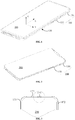
- the mobile terminal includes a middle frame member 100, a display screen 200, a rear cover 300 and a camera assembly 400.
- the middle frame member 100 includes a first middle frame 110 and second middle frame 150 which are slideably arranged relative to each other.
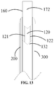
- the second middle frame 150 has a first position and a second position relative to the first middle frame 110. In FIG. 1-FIG. 5 , the second middle frame 150 is in the first position relative to the first middle frame 110. In FIG. 6-FIG. 11 , the second middle frame 150 is in the second position relative to the first middle frame 110.
- the middle frame member 100 is provided with a first lateral surface and second lateral surface which are opposite to each other.
- the display screen 200 is arranged on the side of the middle frame member 100 on which the first lateral surface is positioned.
- the rear cover 300 is arranged on the side of the middle frame member 100 on which the second lateral surface is positioned.
- the camera assembly 400 is arranged on the second middle frame 150 and may move along with the second middle frame 150 relative to the first middle frame 110 to stop in the first position and the second position. As illustrated in FIG. 1 and FIG. 2 , when the second middle frame 150 is in the first position, the camera assembly 400 is hidden in the mobile terminal and covered by another component of the mobile terminal and the camera assembly 400 cannot be seen from the outside. As illustrated in FIG. 6 and FIG.
- the camera assembly 400 when the camera assembly 400 moves to the second position along with the second middle frame 150, the camera assembly 400 may be exposed, the camera assembly 400 may be observed from the outside of the mobile terminal and, in such case, the camera assembly 400 may be used for operations of photographing, making a video call and the like.
- the second middle frame 150 may be in the first position relative to the first middle frame 110 when the camera assembly 400 is not required to be used and the second middle frame 150 may be in the second position relative to the first middle frame 110 when the camera assembly 400 is required to be used.
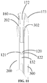
- the first middle frame 110 includes a main bearing plate 120 ( FIG. 11 ) and a side peripheral edge 130.
- the main bearing plate 120 is substantially a rounded rectangle.
- the main bearing plate 120 includes a first lateral surface 121, a second lateral surface 122 and four side edges, the first lateral surface 121 and the second lateral surface 122 are arranged opposite to each other. If a plane parallel to an XY plane is defined with a certain point position in a height direction (for example, a Z-axis direction illustrated in FIG. 1 ) of the mobile terminal, all positions on the first lateral surface 121 may be on one side of the plane and all positions on the second lateral surface 122 may be on the other opposite side of the plane.
- the display screen 200 is loaded on the side of the main bearing plate 120 on which the first lateral surface 121 is positioned.
- the rear cover 300 is loaded on the side of the main bearing plate 120 on which the second lateral surface 122 is positioned.
- the side of the first lateral surface 121 of the main bearing plate 120 may be sunken inwards to form an accommodation cavity, so that the first lateral surface 121 of the main bearing plate 120 is finally presented as not a plane but a combination of multiple stepped surfaces.
- the display screen 200 is at least partially arranged in the accommodation cavity formed in the main bearing plate 120 in a thickness direction.
- the accommodation cavity formed in the main bearing plate 120 may also be arranged to place other components of the mobile terminal, for example, a main board, a power supply and a drive component (motor 600 illustrated in FIG. 16 ).
- a structure such as a slotted hole or a structure such as a bump and a plate body may also be formed on the main bearing plate 120.
- the side facing the display screen 200 belongs to the first lateral surface 121 of the main bearing plate 120 and the side facing the rear cover 300 belongs to the second lateral surface 122 of the main bearing plate 120.
- the side of the main bearing plate on which the first lateral surface 121 is positioned may also be called a front side of the main bearing plate 120, and the display screen 200 is arranged on the front side of the main bearing plate 120.
- the side of the main bearing plate on which the second lateral surface 122 is positioned may also be called a rear side of the main bearing plate 120, and the rear cover 300 is arranged on the rear side of the main bearing plate 120.
- the four side edges of the main bearing plate 120 are a left side edge, a right side edge, a bottom side edge and a top side edge respectively.
- the side peripheral edge 130 is arranged on three side edges, i.e., the left side edge, the right side edge and the bottom side edge respectively, of the main bearing plate 120.
- the side peripheral edge 130 includes a first side peripheral edge 131, a second side peripheral edge 132 and a third side peripheral edge 133 connected between the first and second side peripheral edges 131 and 132.
- the first side peripheral edge 131 and the second side peripheral edge 132 are arranged opposite to each other.
- the first side peripheral edge 131 is arranged on the left side edge of the main bearing plate 120
- the second side peripheral edge 132 is arranged on the right side edge of the main bearing plate 120
- the third side peripheral edge 133 is arranged on the bottom side edge of the main bearing plate 120.
- a height of each side peripheral edge is relatively larger than a height (dimension in the Z-axis direction in FIG. 1 ) of the main bearing plate 120 and thus each side peripheral edge may form, together with the main bearing plate 120, an accommodation space with a certain depth for placing the display screen 200 and the rear cover 300.
- the display screen 200 is placed on the side of the main bearing plate 120 on which the first lateral surface 121 is positioned, and meanwhile, the display screen 200 is fixedly connected with the first, second and third side peripheral edges 131, 132 and 133.
- a buffer edge 201 is arranged at an edge of the display screen 200 fixedly connected with the first, second and third side peripheral edges 131, 132 and 133, and hardness of the buffer edge 201 is lower than hardness of a cover plate of the display screen 200.
- a material for the cover plate of the display screen 200 is glass or hard plastics, so that an internal structure of the display screen 200 may be protected from being impacted and further damaged.
- the hardness of the buffer edge 201 may be lower than hardness of the glass or hardness of the hard plastics.
- the buffer edge 201 may be a plastic strip and the buffer edge 201 may be fixed between the side peripheral edge and the display screen 200 by use of glue.
- a certain plastic deformation space may be reserved for connection between the display screen 200 and the first, second and third side peripheral edges 131, 132 and 133 to prevent influence on stability of connection with the first, second and third side peripheral edges 131, 132 and 133 when the display screen 200is impacted and avoid physical damages such as cracks caused by impact.
- An outer surface of the display screen 200 may be substantially flush with highest positions of the first, second and third side peripheral edges 131, 132 and 133 in the Z-axis direction and thus the outer surface of the display screen 200 may form smooth arc-shaped transitions with edges of the first, second and third side peripheral edges 131, 132 and 133 in the Z-axis direction.
- the rear cover 300 is placed on the side of the main bearing plate 120 on which the second lateral surface 122 is positioned, and meanwhile, the rear cover 300 is fixedly connected with the first, second and third side peripheral edges 131, 132 and 133.
- the rear cover 300 may be connected with the first, second and third side peripheral edges 131, 132 and 133 through the plastic strip and may also be fixedly connected with the first, second and third side peripheral edges 131, 132 and 133 in another manner of glue and the like.
- An outer surface of the rear cover 300 may be substantially flush with the highest positions of the first, second and third side peripheral edges 131, 132 and 133 in the Z-axis direction and thus the outer surface of the rear cover 300 may form smooth arc-shaped transitions with the edges of the first, second and third side peripheral edges 131, 132 and 133 in the Z-axis direction.
- each side peripheral edge 130 may be a plane and may also be an arc-shaped plane.
- the third side peripheral edge 133 may protrude outwards into an arc in a direction far away from the second middle frame 150.
- the first side peripheral edge 131 and the second side peripheral edge 132 may also protrude outwards into arcs in directions far away from each other.
- a groove 134 is formed in the outer surface of the third side peripheral edge 133.
- a contour of the groove 134 is substantially oblong.
- a speaker jack 135 or a connecting port 136 (for example, a port arranged to connecting an external power supply) may be formed in the groove 134.
- the groove 134 is formed in the outer surface of the side peripheral edge which protrudes outwards, and then the speaker jack 135 and the connecting port 136 are formed in a bottom of the groove 134. Positions of the speaker jack 135 and the connecting port 136 may be sunken into the mobile terminal to prevent a finger of a user from touching sharp points of edges of the speaker jack 135 and the connecting port 136 to avoid the finger of the user being cut and improve a user experience.
- a button 137 may be arranged on the first side peripheral edge 131 and the button 137 may be arranged to realize functions of volume regulation and the like.
- decorative edges 138 may be arranged on the edge of each side peripheral edge 130.
- the edge refers to two side edges of the side peripheral edge in the Z-axis direction. More specifically, the side peripheral edge 130 is provided with an outer surface, a first inner surface, a second inner surface, a top surface and a bottom surface.
- the top surface is connected between the outer surface and the first inner surface.
- the first inner surface is connected between the first lateral surface 121 of the main bearing plate 120 and the top surface.
- the bottom surface is connected between the outer surface and the second inner surface.
- the second inner surface is connected between the second lateral surface 122 of the main bearing plate 120 and the bottom surface.
- the decorative edges 138 may be positioned on the top surface and bottom surface of the side peripheral edge 130. Material for the decorative edges 138 may be different from the material for the side peripheral edge 130 and has a high-brightness appearance to make the side peripheral edge 130 more attractive and achieve a more attractive appearance effect.
- the height (dimension in the Z-axis direction, i.e., a distance between the top surface and the bottom surface) of the third side peripheral edge 133 is larger than the heights of the first and second side peripheral edges 131 and 132 and the height of the third side peripheral edge 133 at connecting positions with the first and second side peripheral edges 131 and 132 gradually changes to form arc-shaped transitions between the edge of the third side peripheral edge 133 and the edges of the first and second side peripheral edge 131 and 132.
- the height of the third side peripheral edge 133 is relatively large, so that there is a larger space for arrangement of structures such as the speaker jack 135 and the connecting port 136.
- the side edge where a top end of the display screen 200 is positioned extends beyond the first and second side peripheral edges 131 and 132 and the top side edge of the main bearing plate 120.
- the side edge where a top end of the rear cover 300 is positioned also extends beyond the first and second side peripheral edges 131 and 132 and the top side edge of the main bearing plate 120.
- a long and narrow passage arranged to clamp the second middle frame 150 is formed between a top side edge of the display screen 200 and a top side edge of the rear cover 300.
- the second middle frame 150 includes an auxiliary bearing plate 160 and an outer peripheral edge 170.
- a shape of the auxiliary bearing plate 160 is similar to a shape of the main bearing plate 120 but an area of the auxiliary bearing plate 160 is smaller than an area of the main bearing plate 120.
- the auxiliary bearing plate 160 also includes a first lateral surface 161, a second lateral surface 162 and four side edges, the first lateral surface 161 and the second lateral surface 162 are arranged opposite to each other.
- An orientation of the first lateral surface 161 of the auxiliary bearing plate 160 is the same as an orientation of the first lateral surface 121 of the main bearing plate 120.
- An orientation of the second lateral surface 162 of the auxiliary bearing plate 160 is the same as an orientation of the second lateral surface 122 of the main bearing plate 120.
- the side of the auxiliary bearing plate 160 on which the first lateral surface 161 is positioned is the front side of the mobile terminal.
- the side of the auxiliary bearing plate 160 on which the second lateral surface 162 is positioned is the rear side of the mobile terminal.
- the four side edges of the auxiliary bearing plate 160 are a left side edge, a right side edge, a bottom side edge and a top side edge respectively.
- the bottom side edge of the auxiliary bearing plate 160 forms a slidable connection with the top side edge of the main bearing plate 120.
- the outer peripheral edge 170 is arranged on three side edges, i.e., the left side edge, the right side edge and the top side edge respectively, of the auxiliary bearing plate 160.
- the outer peripheral edge 170 includes a first outer peripheral edge 171, a second outer peripheral edge 172 and a third side peripheral edge 173 connected between the first and second outer peripheral edges 171 and 172.
- the first outer peripheral edge 171 and the second outer peripheral edge 172 are arranged opposite to each other.
- the first outer peripheral edge 171 is arranged on the left side edge of the auxiliary bearing plate 160
- the second outer peripheral edge 172 is arranged on the right side edge of the auxiliary bearing plate 160
- the third outer peripheral edge 173 is arranged on the top side edge of the auxiliary bearing plate 160.
- Decorative edges 178 may be arranged on an edge of the outer peripheral edge 170.
- the edge refers to two side edges of the outer peripheral edge 170 in the Z-axis direction. More specifically, the outer peripheral edge 170 is provided with an outer surface, a first inner surface, a second inner surface, a top surface and a bottom surface.
- the top surface is connected between the outer surface and the first inner surface.
- the first inner surface is connected between the first lateral surface 161 of the auxiliary bearing plate 160 and the top surface.
- the bottom surface is connected between the outer surface and the second inner surface.
- the second inner surface is connected between the second lateral surface 162 of the auxiliary bearing plate 160 and the bottom surface.
- the decorative edges 178 may be positioned on the top surface and bottom surface of the outer peripheral edge 170.
- Material for the decorative edges 178 may be different from a material for the outer peripheral edge 170 and has a high-brightness appearance to make the outer peripheral edge 170 more attractive and achieve a more attractive appearance effect.
- the first side peripheral edge 131 is connected with the first outer peripheral edge 171
- the second side peripheral edge 132 is connected with the second outer peripheral edge 172
- the decorative edges 138 on the side peripheral edge 130 are butted with the decorative edges 178 on the outer peripheral edge 170.
- the display screen 200 is also connected with the first, second and third outer peripheral edges 171, 172 and 173 and, under the condition of high machining accuracy, fit clearances between the display screen 200 and the first, second and third outer peripheral edges 171, 172 and 173 may be indistinguishable for eyes.
- the first middle frame 110 and the second middle frame 150 bear the display screen 200 together.
- a part of the rear cover 300 extending beyond the first middle frame 110 also closely fits with the first, second and third outer peripheral edges 171, 172 and 173 of the second middle frame 150, it is apparent that the rear cover 300 is also connected with the first, second and third outer peripheral edges 171, 172 and 173 and, under the condition of high machining accuracy, fit clearances between the rear cover 300 and the first, second and third outer peripheral edges 171, 172 and 173 may be indistinguishable for eyes.
- each outer peripheral edge 170 is larger than a height of the auxiliary bearing plate 160.
- the outer surface of each outer peripheral edge 170 may be a plane and may also be an arc-shaped plane.
- the first outer peripheral edge 171 and the second outer peripheral edge 172 may protrude outwards into arcs in directions far away from each other.
- the third outer peripheral edge 173 protrudes outwards in a direction far away from the first middle frame 110 and is arc-shaped.
- a groove 174 may also be formed in the outer surface of the third outer peripheral edge 173.
- a structure of the groove 174 may be the same as the structure of the groove 134 in the third side peripheral edge 133. Moreover, the two grooves 174 and 134 are symmetrically formed in a length direction of the mobile terminal. A microphone jack, a connecting port and the like may be formed in the groove 174.
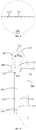
- the height H2 (dimension in the Z-axis direction, i.e., the distance between the top surface and the bottom surface) of the third outer peripheral edge 173 is larger than the heights H1 of the first and second outer peripheral edges 171 and 172, and the height of the third outer peripheral edge 173 at connecting positions with the first and second outer peripheral edges 171 and 172 gradually changes to form arc-shaped transitions between the edge of the third outer peripheral edge 173 and the edges of the first and second outer peripheral edge 171 and 172.
- the height of the third outer peripheral edge 173 is relatively large, so that there is a larger space for arrangement of structures such as the microphone jack and connecting port formed in the third outer peripheral edge 173.
- the third outer peripheral edge 173 form the arc-shaped transitions with the first and second outer peripheral edges 171 and 172, so that impurities such as dust may be prevented from entering the auxiliary bearing plate 160 from a gap between the third outer peripheral edge 173 and the display screen 200.
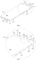
- the second middle frame 150 slides relative to the first middle frame 110, as illustrated in FIG. 7 and FIG. 10 .
- the first side peripheral edge 131 is spaced from the first outer peripheral edge 171 and the second side peripheral edge 132 is spaced from the second outer peripheral edge 172.
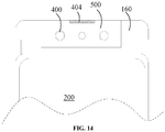
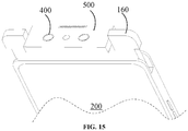
- the camera assembly 400 includes a front camera 401 and an orientation of a light entering surface of the front camera 401 is the same as an orientation of the display screen 200.
- the front camera 401 may be exposed from the side of the auxiliary bearing plate 160 on which the first lateral surface 161 is positioned.
- the auxiliary bearing plate 160 may drive the front camera 401 to be exposed from the edge on which the top end of the display screen 200 is positioned.
- the auxiliary bearing plate 160 drives the front camera 401 to be hidden between the top end of the display screen 200 and the top end of the rear cover 300.
- the camera assembly 400 further includes a face recognition component 403.
- the face recognition component 403 includes components, such as an infrared lens, a floodlight sensing element, a distance sensor and a dot matrix projector, arranged on the auxiliary bearing plate 160 and these components may cooperate for face recognition.
- the camera assembly 400 may further include an ambient light sensor.
- the ambient light sensor may also be arranged on the side of the auxiliary bearing plate 160 on which the first lateral surface 161 is positioned, and is integrated with the face recognition component 403 and the front camera 401.
- a protective cover plate 163 is arranged on the side of the auxiliary bearing plate 160 on which the first lateral surface 161 is positioned, and a light permeable region corresponding to the front camera 401 is arranged on the protective cover plate 163.
- the light permeable region matched with the components, such as the infrared lens, the floodlight sensing element, the distance sensor and the dot matrix project, is also formed on the protective cover plate 163.
- the protective cover plate 163 may be monolithic transparent glass and may also be glass with a transparent region arranged at a position corresponding to a component such as the front camera 401.
- the protective cover plate 163 contacts with the first outer peripheral edge 171, the second outer peripheral edge 172 and the third outer peripheral edge 173.
- the protective cover plate 163 may be arranged to protect the front camera 401 and the face recognition component 403.
- structural integrity thereof is higher.
- the camera assembly 400 further includes a rear camera 402.
- An orientation of a light entering surface of the rear camera 402 is opposite to the orientation of the display screen 200.
- the rear camera 402 may be exposed from the side where the second lateral surface 162 is positioned, of the auxiliary bearing plate 160.
- the auxiliary bearing plate 160 may drive the rear camera 402 to be exposed from the edge where the top end of the rear cover 300 is positioned.
- the auxiliary bearing plate 160 drives the rear camera 402 to be hidden between the top end of the rear cover 300 and the top end of the display screen 200.
- the mobile phone may further include a flash lamp 405.
- the flash lamp 405 and the rear camera 402 are integrated on the auxiliary bearing plate 160.
- Another protective cover plate 164 is arranged on the side of the auxiliary bearing plate 160 on which the second lateral surface 162 is positioned, and a light permeable region corresponding to the rear camera 402 is arranged on the protective cover plate 164.
- the protective cover plate 164 may be monolithic transparent glass and may also be glass with a transparent region arranged at a position corresponding to a component such as the rear camera 402.
- An edge of the protective cover plate 164 contacts with the first side peripheral edge 131, the second side peripheral edge 132 and the third side peripheral edge 133.
- the protective cover plate 164 may be arranged to protect components such as the rear camera 402 and the flash lamp 405.
- the structural integrity thereof is higher.
- Positions of the rear camera 402 and the front camera 401 on the auxiliary bearing plate 160 are mutually staggered. Since the cameras have certain heights, arranging the rear camera 402 and the front camera 401 in a staggered manner may avoid superposition on height of the rear camera 402 and the front camera 401 on height, prevent an excessively dimension of the auxiliary bearing plate 160 in the Z-axis direction and reduce an overall height of the mobile terminal.
- a thickness d (extending dimension of the third outer peripheral edge 173 in the length direction of the mobile terminal, i.e., the Z-axis direction) of the third outer peripheral edge 173, on the side of the auxiliary bearing plate 160 on which the second lateral surface 162 is positioned, is gradually increased from joints with the first and second outer peripheral edges 171 and 172 to a middle part respectively, and a matched arc-shaped notch 301 is correspondingly formed in the rear cover 300.
- the rear camera 402 is positioned on the auxiliary bearing plate 160 and corresponds to the middle part of the third outer peripheral edge 173, and is exposed from the arc-shaped notch 301 in the second position.
- the arc-shaped notch 301 is provided and the rear camera 402 is exposed from the arc-shaped notch 301, so that a moving distance of the rear camera 402, and thus a moving distance of the auxiliary bearing plate 160, during switching from the first position to the second position may be shortened.
- the flash lamp 405 is arranged a on the side of the auxiliary bearing plate 160 on which the second lateral surface 162 is positioned, and corresponds to a maximum thickness of the third outer peripheral edge 173.
- a thickness d of the middle part of the third outer peripheral edge 173, on the side of the auxiliary bearing plate 160 on which the second lateral surface 162 is positioned is larger than thicknesses d of two end parts.
- the thickness of the third outer peripheral edge 173, on the side of the auxiliary bearing plate 160 on which the second lateral surface 162 is positioned may be gradually decreased from the middle part to the two end parts and may also change suddenly.
- the edge of the display screen 200 is provided with a stepped slot 202.
- the stepped slot 202 may be formed in the buffer edge 201.
- FIG. 5 when the auxiliary bearing plate 160 is in the first position, part of a structure of the outer peripheral edge 170 is accommodated in the stepped slot 202.
- the top surface of the outer peripheral edge 170 is partially covered by the edge of the display screen 200, the top surface of the third outer peripheral edge 170 is partially exposed in an X-axis direction and, correspondingly, the top surfaces of the first and second outer peripheral edges 171 and 172 are partially exposed in a Y-axis direction.
- An edge of the rear cover 300 is provided with a stepped slot 302 and, when the auxiliary bearing plate 160 is in the first position, part of the structure of the outer peripheral edge 170 is accommodated in the stepped slot 302.
- auxiliary bearing plate 160 When the auxiliary bearing plate 160 is in the first position and if the fit clearance between the edge of the display screen 200 and the outer peripheral edge 170 is too small, a receiving effect of the telephone receiver may be influenced.
- a telephone receiver slot 175 is formed in the third outer peripheral edge 173.
- the third outer peripheral edge 173 includes a top surface 181, an outer surface 182 and an inner surface 183.
- the inner surface 183 is connected between the top surface 181 and the first lateral surface 161 of the auxiliary bearing plate 160.
- a bottom of the telephone receiver slot 175 is provided with two boundaries in the Z-axis direction, i.e., a first boundary 176 and a second boundary 177, and two boundaries in the Y-axis direction, i.e., a third boundary 178 and a fourth boundary 179.
- the first boundary 176 is arc-shaped, a middle part of the first boundary 176 is flush with an intersection line of the top surface 181 and the outer surface 182 and two end parts of the first boundary 176 are positioned on the top surface 181.
- the second boundary 177 is flush with the first lateral surface 161 of the auxiliary bearing plate 160.
- Both of the third boundary 178 and the fourth boundary 179 are intersected with the inner surface 183 and the top surface 181 to endow the telephone receiver slot 175 with a certain depth (substantially an extending distance in the Z-axis direction) and length (an extending direction in the Y-axis direction) and, meanwhile, a thickness (extending dimension in the X-axis direction) of the part on the third outer peripheral edge 173, where the telephone receiver slot 175 is formed, is smaller than a thickness of the other part.
- the top surface 181 of the third outer peripheral edge 173 is partially covered by the edge of the display screen 200 and the middle part of the first boundary 176 of the telephone receiver slot 175 is exposed.
- a passage may be formed between the exposed part of the telephone receiver slot 175 and the telephone receiver on the first lateral surface 161 of the auxiliary bearing plate 160, so that the telephone receiver may transmit sounds to the outside through the telephone receiver slot 175 and a receiving effect of the telephone receiver is improved. Therefore, even if the auxiliary bearing plate 160 is in the first position, influence on use of the telephone receiver may also be avoided.
- the butted edges of the first side peripheral edge 131 and the first outer peripheral edge 171 may be linear and thus a gap formed when the first side peripheral edge 131 is connected with the first outer peripheral edge 171 may be linear.
- the butted edges of the second side peripheral edge 132 and the second outer peripheral edge 172 may be linear and thus a gap formed when the second side peripheral edge 132 is connected with the second outer peripheral edge 172 may be linear.
- the gap formed when the first side peripheral edge 131 is connected with the first outer peripheral edge 171 may be arc-shaped.
- the gap formed when the second side peripheral edge 132 is connected with the second outer peripheral edge 172 may be arc-shaped.
- the gap formed when the first side peripheral edge 131 is connected with the first outer peripheral edge 171 may be broken-line-shaped.
- the gap formed when the second side peripheral edge 132 is connected with the second outer peripheral edge 172 may be broken-line-shaped.
- the mobile phone further includes a rotating block 500 rotatablely arranged on the auxiliary bearing plate 160.
- a rotating shaft of the rotating block 500 is parallel to a width direction (Y-axis extending direction) of the mobile terminal.
- the rotating block 500 may rotate relative to the auxiliary bearing plate 160.
- a rotating space of the rotating block 500 is limited and it may not rotate relative to the auxiliary bearing plate 160.
- the camera assembly 400 is arranged on the rotating block 500.
- the camera assembly 400 is arranged on the rotating block 500.
- the camera assembly 400 may be used as the front camera or the rear camera by changing a position of the rotating block 500 relative to the auxiliary bearing plate 160, and arrangement of cameras in two orientations is avoided.
- Other components such as the telephone receiver 404 may also be arranged on the rotating block 500.
- a corresponding transmission mechanism may also be arranged for the slidable connection between the auxiliary bearing plate 160 and the main bearing plate 120.
- the auxiliary bearing plate 160 and the main bearing plate 120 may be switched to and fro more automatically between the first position and the second position.
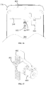
- the mobile terminal includes a motor 600.
- a gear 601 is arranged on an output shaft of the motor 600, a rack 602 is arranged on the auxiliary bearing plate 160, and the rack 602 cooperates with the gear 601 to allow the auxiliary bearing plate 160 to be switched between the first position and the second position relative to the main bearing plate 120 by the motor 600.
- the motor 600 may form a communication connection with the main board of the mobile terminal and receive a control signal sent by the main board to rotate in different directions, thereby driving the auxiliary bearing plate 160 to be switched between the first position and the second position.
- the motor 600 may be fixed on the main bearing plate 120.
- a sliding rail and sliding chute which cooperate with each other may also be arranged between the main bearing plate 120 and the auxiliary bearing plate 160 to ensure more smooth movement of the auxiliary bearing plate 160 relative to the main bearing plate 120.
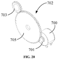
- the mobile terminal includes a motor 700, a gearbox 702, a screw rod 704 and a sliding rod 706.
- An output shaft of the gearbox 702 is parallel to the moving direction of the auxiliary bearing plate 160.
- the gearbox 702 is connected between the motor 700 and the screw rod 704 to enable the motor 700 to drive the screw rod 704 into rotation.
- a helical groove 708 is formed in the screw rod 704.
- the sliding rod 706 is connected with the auxiliary bearing plate 160.
- the sliding rod 706 is provided with a snap ring 709 cooperating with the helical groove 708.
- the screw rod 704 rotates to drive the snap ring 709 on the sliding rod 706 to move in the helical groove 708 to further switch the auxiliary bearing plate 160 between the first position and the second position relative to the main bearing plate 120.
- the snap ring 709 may be rotatablely arranged on the sliding rod 706, so that a frictional force generated in a relative movement process of the sliding rod 706 and the screw rod 704 may be reduced, the sliding rod may move relative to the screw rod 704 in a more labor-saving manner, and more energy is saved.
- the motor 700 may form a communication connection with the main board of the mobile terminal and receive the control signal sent by the main board to rotate in different directions, thereby driving the auxiliary bearing plate 160 to be switched between the first position and the second position.
- the sliding rod 706 may be arranged to be hollow and an internal space may be used as a wiring passage to form a communication connection between the camera assembly 400 on the auxiliary bearing plate 160 and the main board of the mobile terminal.
- the gearbox 702 includes a first gear 703 and second gear 705 which are mutually meshed.
- the first gear 703 may cooperate with the screw rod 704.
- a corresponding matched gear is arranged at an end part of the screw rod 704 to drive the screw rod 704 into rotation.
- the second gear 705 may be meshed with an output gear 701 on the output shaft of the motor 700.
- the gear number of the gearbox 702 and a dimension proportion of each gear may be reasonably set according to the dimension of the mobile terminal and a space configuration of the other components.
- the display screen 200 may be an OLED display screen or an LCD screen.
- the display screen 200 may carry a touch assembly to endow the display screen 200 with a touch operation function.
- the rear cover 300 may be made of a metal material, a glass material or a ceramic material.
- a ratio of a display area of the display screen 200 to an area of an outer contour of the middle frame member 100 is more than or equal to 83%.
Landscapes
- Engineering & Computer Science (AREA)
- Signal Processing (AREA)
- Telephone Set Structure (AREA)
Applications Claiming Priority (1)
| Application Number | Priority Date | Filing Date | Title |
|---|---|---|---|
| CN201820244082.8U CN207968576U (zh) | 2018-02-09 | 2018-02-09 | 手机 |
Publications (2)
| Publication Number | Publication Date |
|---|---|
| EP3525431A1 true EP3525431A1 (fr) | 2019-08-14 |
| EP3525431B1 EP3525431B1 (fr) | 2020-05-13 |
Family
ID=63739120
Family Applications (1)
| Application Number | Title | Priority Date | Filing Date |
|---|---|---|---|
| EP18210411.7A Active EP3525431B1 (fr) | 2018-02-09 | 2018-12-05 | Téléphone mobile avec caméra |
Country Status (4)
| Country | Link |
|---|---|
| US (1) | US10897526B2 (fr) |
| EP (1) | EP3525431B1 (fr) |
| CN (1) | CN207968576U (fr) |
| WO (1) | WO2019153870A1 (fr) |
Cited By (1)
| Publication number | Priority date | Publication date | Assignee | Title |
|---|---|---|---|---|
| EP3661172A1 (fr) * | 2018-11-29 | 2020-06-03 | Samsung Electronics Co., Ltd. | Rotation de la caméra d'un téléphone mobile en fonction du mode de fonctionnement |
Families Citing this family (30)
| Publication number | Priority date | Publication date | Assignee | Title |
|---|---|---|---|---|
| USD821376S1 (en) * | 2015-10-02 | 2018-06-26 | Samsung Electronics Co., Ltd. | Electronic device |
| USD828828S1 (en) * | 2015-10-02 | 2018-09-18 | Samsung Electronics Co., Ltd. | Electronic device |
| US11249714B2 (en) | 2017-09-13 | 2022-02-15 | Magical Technologies, Llc | Systems and methods of shareable virtual objects and virtual objects as message objects to facilitate communications sessions in an augmented reality environment |
| WO2019079826A1 (fr) | 2017-10-22 | 2019-04-25 | Magical Technologies, Llc | Systèmes, procédés et appareils d'assistants numériques dans un environnement de réalité augmentée et détermination locale d'un placement d'objet virtuel et appareils à objectif unique ou multidirectionnel en tant que portails entre un monde physique et un composant du monde numérique de l'environnement de réalité augmentée |
| USD882557S1 (en) * | 2017-11-08 | 2020-04-28 | Guangdong Oppo Mobile Telecommunications Corp., Ltd. | Mobile phone |
| USD892781S1 (en) * | 2018-01-12 | 2020-08-11 | Samsung Electronics Co., Ltd. | Mobile phone |
| USD892780S1 (en) * | 2018-01-12 | 2020-08-11 | Samsung Electronics Co., Ltd. | Mobile phone |
| US10904374B2 (en) | 2018-01-24 | 2021-01-26 | Magical Technologies, Llc | Systems, methods and apparatuses to facilitate gradual or instantaneous adjustment in levels of perceptibility of virtual objects or reality object in a digital scene |
| US11398088B2 (en) | 2018-01-30 | 2022-07-26 | Magical Technologies, Llc | Systems, methods and apparatuses to generate a fingerprint of a physical location for placement of virtual objects |
| JP1629382S (fr) * | 2018-02-05 | 2019-04-15 | ||
| CN207968576U (zh) | 2018-02-09 | 2018-10-12 | 广东欧珀移动通信有限公司 | 手机 |
| USD879733S1 (en) * | 2018-03-16 | 2020-03-31 | Guangdong Oppo Mobile Telecommunications Corp., Ltd. | Mobile phone |
| CN209105221U (zh) * | 2018-09-07 | 2019-07-12 | Oppo广东移动通信有限公司 | 移动终端 |
| CN112887456B (zh) | 2018-11-06 | 2023-03-14 | Oppo广东移动通信有限公司 | 成像模组、摄像头组件及电子装置 |
| CN109167908B (zh) * | 2018-11-06 | 2021-03-12 | Oppo广东移动通信有限公司 | 成像模组、摄像头组件及电子装置 |
| CN111258373A (zh) * | 2018-11-30 | 2020-06-09 | 北京小米移动软件有限公司 | 一种电子设备 |
| JP1651187S (fr) * | 2019-01-09 | 2020-01-27 | ||
| US11467656B2 (en) | 2019-03-04 | 2022-10-11 | Magical Technologies, Llc | Virtual object control of a physical device and/or physical device control of a virtual object |
| CN111835887B (zh) * | 2019-04-16 | 2022-04-08 | 北京小米移动软件有限公司 | 摄像头结构和电子设备 |
| CN210183364U (zh) | 2019-04-25 | 2020-03-24 | Oppo广东移动通信有限公司 | 移动终端 |
| KR102775303B1 (ko) * | 2019-05-09 | 2025-03-05 | 삼성전자주식회사 | 슬라이드 바디를 포함하는 전자 장치 |
| KR102639270B1 (ko) * | 2019-05-22 | 2024-02-22 | 삼성전자주식회사 | 카메라 팝업 구조를 포함하는 전자 장치 |
| CN110113461B (zh) * | 2019-06-15 | 2021-06-01 | 宁波团团工业设计有限公司 | 一种能显示和隐藏手机镜头的屏幕升降结构 |
| KR20210022921A (ko) * | 2019-08-21 | 2021-03-04 | 삼성전자주식회사 | 슬라이딩 동작되는 전자 장치 |
| CN110572500B (zh) * | 2019-10-29 | 2020-11-13 | 维沃移动通信(杭州)有限公司 | 电子设备 |
| CN210429140U (zh) * | 2019-11-27 | 2020-04-28 | 北京京东方光电科技有限公司 | 显示装置 |
| CN111225087A (zh) * | 2019-12-11 | 2020-06-02 | 王云飞 | 一种手机镜头的升降模组 |
| CN111427419B (zh) * | 2020-03-18 | 2021-11-23 | 维沃移动通信有限公司 | 翻转功能组件及电子设备 |
| CN111885239A (zh) * | 2020-07-31 | 2020-11-03 | 华勤技术有限公司 | 一种移动终端 |
| EP4184284B1 (fr) * | 2020-11-06 | 2025-05-07 | Samsung Electronics Co., Ltd. | Dispositif électronique à module de caméra et procédé de fonctionnement dudit dispositif |
Citations (4)
| Publication number | Priority date | Publication date | Assignee | Title |
|---|---|---|---|---|
| WO2017008525A1 (fr) * | 2015-07-10 | 2017-01-19 | 深圳市华锐博光电有限公司 | Téléphone mobile à couvercle coulissant ultramince et sans cadre et procédé d'utilisation |
| CN106899721A (zh) * | 2017-04-28 | 2017-06-27 | 广东欧珀移动通信有限公司 | 电子装置 |
| EP3255867A1 (fr) * | 2015-07-13 | 2017-12-13 | Guangdong Oppo Mobile Telecommunications Corp., Ltd | Terminal mobile à écran souple avec deux extrémités pliables |
| CN108471493A (zh) * | 2018-06-02 | 2018-08-31 | Oppo广东移动通信有限公司 | 成像组件及电子设备 |
Family Cites Families (8)
| Publication number | Priority date | Publication date | Assignee | Title |
|---|---|---|---|---|
| US8073510B2 (en) * | 2007-09-10 | 2011-12-06 | Samkwang Ind Co., Ltd. | Mobile communication terminal |
| CN202168120U (zh) * | 2011-08-18 | 2012-03-14 | 希姆通信息技术(上海)有限公司 | 手机 |
| CN109246262B (zh) * | 2014-07-23 | 2021-10-01 | 荣耀终端有限公司 | 一种终端设备 |
| CN205320124U (zh) * | 2016-01-26 | 2016-06-15 | 孔岳 | 一种全屏手机 |
| CN106790801A (zh) * | 2016-12-15 | 2017-05-31 | 卢春宁 | 一种具有模块化可伸缩的移动通讯设备 |
| CN107071103A (zh) * | 2017-03-28 | 2017-08-18 | 北京小米移动软件有限公司 | 移动终端 |
| US20190033926A1 (en) * | 2017-07-26 | 2019-01-31 | Wuhan China Star Optoelectronics Semiconductor Display Technology Co., Ltd. | Mobile terminal |
| CN207968576U (zh) * | 2018-02-09 | 2018-10-12 | 广东欧珀移动通信有限公司 | 手机 |
-
2018
- 2018-02-09 CN CN201820244082.8U patent/CN207968576U/zh not_active Expired - Fee Related
- 2018-12-05 EP EP18210411.7A patent/EP3525431B1/fr active Active
- 2018-12-11 WO PCT/CN2018/120364 patent/WO2019153870A1/fr not_active Ceased
- 2018-12-12 US US16/217,788 patent/US10897526B2/en not_active Expired - Fee Related
Patent Citations (6)
| Publication number | Priority date | Publication date | Assignee | Title |
|---|---|---|---|---|
| WO2017008525A1 (fr) * | 2015-07-10 | 2017-01-19 | 深圳市华锐博光电有限公司 | Téléphone mobile à couvercle coulissant ultramince et sans cadre et procédé d'utilisation |
| US20180205809A1 (en) * | 2015-07-10 | 2018-07-19 | Shenzhen Huaruibo Photoelectric Co., Ltd. | Borderless ultra-thin slide phone and method for using the same |
| EP3255867A1 (fr) * | 2015-07-13 | 2017-12-13 | Guangdong Oppo Mobile Telecommunications Corp., Ltd | Terminal mobile à écran souple avec deux extrémités pliables |
| CN106899721A (zh) * | 2017-04-28 | 2017-06-27 | 广东欧珀移动通信有限公司 | 电子装置 |
| EP3396933A1 (fr) * | 2017-04-28 | 2018-10-31 | Guangdong OPPO Mobile Telecommunications Corp., Ltd. | Dispositif électronique portable |
| CN108471493A (zh) * | 2018-06-02 | 2018-08-31 | Oppo广东移动通信有限公司 | 成像组件及电子设备 |
Cited By (2)
| Publication number | Priority date | Publication date | Assignee | Title |
|---|---|---|---|---|
| EP3661172A1 (fr) * | 2018-11-29 | 2020-06-03 | Samsung Electronics Co., Ltd. | Rotation de la caméra d'un téléphone mobile en fonction du mode de fonctionnement |
| US10686971B1 (en) | 2018-11-29 | 2020-06-16 | Samsung Electronics Co., Ltd. | Electronic device including a camera capable of being a front camera and a rear camera and an operating method thereof |
Also Published As
| Publication number | Publication date |
|---|---|
| CN207968576U (zh) | 2018-10-12 |
| EP3525431B1 (fr) | 2020-05-13 |
| WO2019153870A1 (fr) | 2019-08-15 |
| US20190253542A1 (en) | 2019-08-15 |
| US10897526B2 (en) | 2021-01-19 |
Similar Documents
| Publication | Publication Date | Title |
|---|---|---|
| US10897526B2 (en) | Mobile phone | |
| US10419589B2 (en) | Mobile phone with slidable housing assembly for hiding and exposing a camera | |
| EP3661174B1 (fr) | Mécanisme de transmission et terminal mobile | |
| EP3525424B1 (fr) | Terminal mobile | |
| CN100539610C (zh) | 携带式设备 | |
| US8576549B2 (en) | Two-axis hinge and mobile device | |
| US10574799B2 (en) | Mobile terminal with camera arranged on movable shell | |
| CN208158640U (zh) | 移动终端 | |
| US11044391B2 (en) | Electronic device having sliding mechanism | |
| US12519877B2 (en) | Hook mechanism, support apparatus, and electronic device | |
| US20090233659A1 (en) | Portable electronic device | |
| US8442323B2 (en) | Handwriting recognition device having an externally defined input area | |
| WO2020037618A1 (fr) | Dispositif électronique et procédé de commande associé | |
| HK40011035A (en) | Mobile phone with camera | |
| HK40011035B (en) | Mobile phone with camera | |
| US7433468B2 (en) | Electrical device for adjusting the angle between a top module and a bottom module | |
| US20100248795A1 (en) | Information processing terminal | |
| HK40009370B (en) | Mobile phone with camera | |
| HK40009370A (en) | Mobile phone with camera | |
| WO2020048164A1 (fr) | Terminal mobile | |
| CN114077122A (zh) | 驱动装置及其电子设备 | |
| HK40012082B (en) | A mobile terminal with sliding shells comprising a camera | |
| CN114598758A (zh) | 驱动装置、摄像头模组及电子设备 | |
| HK40030536A (en) | Transmission mechanism and mobile terminal | |
| HK40030536B (en) | Transmission mechanism and mobile terminal |
Legal Events
| Date | Code | Title | Description |
|---|---|---|---|
| PUAI | Public reference made under article 153(3) epc to a published international application that has entered the european phase |
Free format text: ORIGINAL CODE: 0009012 |
|
| STAA | Information on the status of an ep patent application or granted ep patent |
Free format text: STATUS: THE APPLICATION HAS BEEN PUBLISHED |
|
| AK | Designated contracting states |
Kind code of ref document: A1 Designated state(s): AL AT BE BG CH CY CZ DE DK EE ES FI FR GB GR HR HU IE IS IT LI LT LU LV MC MK MT NL NO PL PT RO RS SE SI SK SM TR |
|
| AX | Request for extension of the european patent |
Extension state: BA ME |
|
| STAA | Information on the status of an ep patent application or granted ep patent |
Free format text: STATUS: REQUEST FOR EXAMINATION WAS MADE |
|
| RAP1 | Party data changed (applicant data changed or rights of an application transferred) |
Owner name: GUANGDONG OPPO MOBILE TELECOMMUNICATIONS CORP., LT |
|
| 17P | Request for examination filed |
Effective date: 20191111 |
|
| RBV | Designated contracting states (corrected) |
Designated state(s): AL AT BE BG CH CY CZ DE DK EE ES FI FR GB GR HR HU IE IS IT LI LT LU LV MC MK MT NL NO PL PT RO RS SE SI SK SM TR |
|
| GRAP | Despatch of communication of intention to grant a patent |
Free format text: ORIGINAL CODE: EPIDOSNIGR1 |
|
| STAA | Information on the status of an ep patent application or granted ep patent |
Free format text: STATUS: GRANT OF PATENT IS INTENDED |
|
| INTG | Intention to grant announced |
Effective date: 20200124 |
|
| GRAS | Grant fee paid |
Free format text: ORIGINAL CODE: EPIDOSNIGR3 |
|
| GRAA | (expected) grant |
Free format text: ORIGINAL CODE: 0009210 |
|
| STAA | Information on the status of an ep patent application or granted ep patent |
Free format text: STATUS: THE PATENT HAS BEEN GRANTED |
|
| AK | Designated contracting states |
Kind code of ref document: B1 Designated state(s): AL AT BE BG CH CY CZ DE DK EE ES FI FR GB GR HR HU IE IS IT LI LT LU LV MC MK MT NL NO PL PT RO RS SE SI SK SM TR |
|
| REG | Reference to a national code |
Ref country code: GB Ref legal event code: FG4D |
|
| REG | Reference to a national code |
Ref country code: CH Ref legal event code: EP |
|
| REG | Reference to a national code |
Ref country code: DE Ref legal event code: R096 Ref document number: 602018004635 Country of ref document: DE |
|
| REG | Reference to a national code |
Ref country code: AT Ref legal event code: REF Ref document number: 1271742 Country of ref document: AT Kind code of ref document: T Effective date: 20200615 |
|
| REG | Reference to a national code |
Ref country code: HK Ref legal event code: DE Ref document number: 40011035 Country of ref document: HK |
|
| REG | Reference to a national code |
Ref country code: LT Ref legal event code: MG4D |
|
| REG | Reference to a national code |
Ref country code: NL Ref legal event code: MP Effective date: 20200513 |
|
| PG25 | Lapsed in a contracting state [announced via postgrant information from national office to epo] |
Ref country code: PT Free format text: LAPSE BECAUSE OF FAILURE TO SUBMIT A TRANSLATION OF THE DESCRIPTION OR TO PAY THE FEE WITHIN THE PRESCRIBED TIME-LIMIT Effective date: 20200914 Ref country code: LT Free format text: LAPSE BECAUSE OF FAILURE TO SUBMIT A TRANSLATION OF THE DESCRIPTION OR TO PAY THE FEE WITHIN THE PRESCRIBED TIME-LIMIT Effective date: 20200513 Ref country code: FI Free format text: LAPSE BECAUSE OF FAILURE TO SUBMIT A TRANSLATION OF THE DESCRIPTION OR TO PAY THE FEE WITHIN THE PRESCRIBED TIME-LIMIT Effective date: 20200513 Ref country code: GR Free format text: LAPSE BECAUSE OF FAILURE TO SUBMIT A TRANSLATION OF THE DESCRIPTION OR TO PAY THE FEE WITHIN THE PRESCRIBED TIME-LIMIT Effective date: 20200814 Ref country code: NO Free format text: LAPSE BECAUSE OF FAILURE TO SUBMIT A TRANSLATION OF THE DESCRIPTION OR TO PAY THE FEE WITHIN THE PRESCRIBED TIME-LIMIT Effective date: 20200813 Ref country code: IS Free format text: LAPSE BECAUSE OF FAILURE TO SUBMIT A TRANSLATION OF THE DESCRIPTION OR TO PAY THE FEE WITHIN THE PRESCRIBED TIME-LIMIT Effective date: 20200913 Ref country code: SE Free format text: LAPSE BECAUSE OF FAILURE TO SUBMIT A TRANSLATION OF THE DESCRIPTION OR TO PAY THE FEE WITHIN THE PRESCRIBED TIME-LIMIT Effective date: 20200513 |
|
| PG25 | Lapsed in a contracting state [announced via postgrant information from national office to epo] |
Ref country code: BG Free format text: LAPSE BECAUSE OF FAILURE TO SUBMIT A TRANSLATION OF THE DESCRIPTION OR TO PAY THE FEE WITHIN THE PRESCRIBED TIME-LIMIT Effective date: 20200813 Ref country code: RS Free format text: LAPSE BECAUSE OF FAILURE TO SUBMIT A TRANSLATION OF THE DESCRIPTION OR TO PAY THE FEE WITHIN THE PRESCRIBED TIME-LIMIT Effective date: 20200513 Ref country code: HR Free format text: LAPSE BECAUSE OF FAILURE TO SUBMIT A TRANSLATION OF THE DESCRIPTION OR TO PAY THE FEE WITHIN THE PRESCRIBED TIME-LIMIT Effective date: 20200513 Ref country code: LV Free format text: LAPSE BECAUSE OF FAILURE TO SUBMIT A TRANSLATION OF THE DESCRIPTION OR TO PAY THE FEE WITHIN THE PRESCRIBED TIME-LIMIT Effective date: 20200513 |
|
| REG | Reference to a national code |
Ref country code: AT Ref legal event code: MK05 Ref document number: 1271742 Country of ref document: AT Kind code of ref document: T Effective date: 20200513 |
|
| PG25 | Lapsed in a contracting state [announced via postgrant information from national office to epo] |
Ref country code: AL Free format text: LAPSE BECAUSE OF FAILURE TO SUBMIT A TRANSLATION OF THE DESCRIPTION OR TO PAY THE FEE WITHIN THE PRESCRIBED TIME-LIMIT Effective date: 20200513 Ref country code: NL Free format text: LAPSE BECAUSE OF FAILURE TO SUBMIT A TRANSLATION OF THE DESCRIPTION OR TO PAY THE FEE WITHIN THE PRESCRIBED TIME-LIMIT Effective date: 20200513 |
|
| PG25 | Lapsed in a contracting state [announced via postgrant information from national office to epo] |
Ref country code: RO Free format text: LAPSE BECAUSE OF FAILURE TO SUBMIT A TRANSLATION OF THE DESCRIPTION OR TO PAY THE FEE WITHIN THE PRESCRIBED TIME-LIMIT Effective date: 20200513 Ref country code: AT Free format text: LAPSE BECAUSE OF FAILURE TO SUBMIT A TRANSLATION OF THE DESCRIPTION OR TO PAY THE FEE WITHIN THE PRESCRIBED TIME-LIMIT Effective date: 20200513 Ref country code: EE Free format text: LAPSE BECAUSE OF FAILURE TO SUBMIT A TRANSLATION OF THE DESCRIPTION OR TO PAY THE FEE WITHIN THE PRESCRIBED TIME-LIMIT Effective date: 20200513 Ref country code: CZ Free format text: LAPSE BECAUSE OF FAILURE TO SUBMIT A TRANSLATION OF THE DESCRIPTION OR TO PAY THE FEE WITHIN THE PRESCRIBED TIME-LIMIT Effective date: 20200513 Ref country code: DK Free format text: LAPSE BECAUSE OF FAILURE TO SUBMIT A TRANSLATION OF THE DESCRIPTION OR TO PAY THE FEE WITHIN THE PRESCRIBED TIME-LIMIT Effective date: 20200513 Ref country code: ES Free format text: LAPSE BECAUSE OF FAILURE TO SUBMIT A TRANSLATION OF THE DESCRIPTION OR TO PAY THE FEE WITHIN THE PRESCRIBED TIME-LIMIT Effective date: 20200513 Ref country code: IT Free format text: LAPSE BECAUSE OF FAILURE TO SUBMIT A TRANSLATION OF THE DESCRIPTION OR TO PAY THE FEE WITHIN THE PRESCRIBED TIME-LIMIT Effective date: 20200513 Ref country code: SM Free format text: LAPSE BECAUSE OF FAILURE TO SUBMIT A TRANSLATION OF THE DESCRIPTION OR TO PAY THE FEE WITHIN THE PRESCRIBED TIME-LIMIT Effective date: 20200513 |
|
| REG | Reference to a national code |
Ref country code: DE Ref legal event code: R097 Ref document number: 602018004635 Country of ref document: DE |
|
| PG25 | Lapsed in a contracting state [announced via postgrant information from national office to epo] |
Ref country code: SK Free format text: LAPSE BECAUSE OF FAILURE TO SUBMIT A TRANSLATION OF THE DESCRIPTION OR TO PAY THE FEE WITHIN THE PRESCRIBED TIME-LIMIT Effective date: 20200513 Ref country code: PL Free format text: LAPSE BECAUSE OF FAILURE TO SUBMIT A TRANSLATION OF THE DESCRIPTION OR TO PAY THE FEE WITHIN THE PRESCRIBED TIME-LIMIT Effective date: 20200513 |
|
| PLBE | No opposition filed within time limit |
Free format text: ORIGINAL CODE: 0009261 |
|
| STAA | Information on the status of an ep patent application or granted ep patent |
Free format text: STATUS: NO OPPOSITION FILED WITHIN TIME LIMIT |
|
| 26N | No opposition filed |
Effective date: 20210216 |
|
| PG25 | Lapsed in a contracting state [announced via postgrant information from national office to epo] |
Ref country code: MC Free format text: LAPSE BECAUSE OF FAILURE TO SUBMIT A TRANSLATION OF THE DESCRIPTION OR TO PAY THE FEE WITHIN THE PRESCRIBED TIME-LIMIT Effective date: 20200513 |
|
| REG | Reference to a national code |
Ref country code: BE Ref legal event code: MM Effective date: 20201231 |
|
| PG25 | Lapsed in a contracting state [announced via postgrant information from national office to epo] |
Ref country code: IE Free format text: LAPSE BECAUSE OF NON-PAYMENT OF DUE FEES Effective date: 20201205 Ref country code: LU Free format text: LAPSE BECAUSE OF NON-PAYMENT OF DUE FEES Effective date: 20201205 |
|
| PG25 | Lapsed in a contracting state [announced via postgrant information from national office to epo] |
Ref country code: TR Free format text: LAPSE BECAUSE OF FAILURE TO SUBMIT A TRANSLATION OF THE DESCRIPTION OR TO PAY THE FEE WITHIN THE PRESCRIBED TIME-LIMIT Effective date: 20200513 Ref country code: MT Free format text: LAPSE BECAUSE OF FAILURE TO SUBMIT A TRANSLATION OF THE DESCRIPTION OR TO PAY THE FEE WITHIN THE PRESCRIBED TIME-LIMIT Effective date: 20200513 Ref country code: CY Free format text: LAPSE BECAUSE OF FAILURE TO SUBMIT A TRANSLATION OF THE DESCRIPTION OR TO PAY THE FEE WITHIN THE PRESCRIBED TIME-LIMIT Effective date: 20200513 |
|
| PG25 | Lapsed in a contracting state [announced via postgrant information from national office to epo] |
Ref country code: MK Free format text: LAPSE BECAUSE OF FAILURE TO SUBMIT A TRANSLATION OF THE DESCRIPTION OR TO PAY THE FEE WITHIN THE PRESCRIBED TIME-LIMIT Effective date: 20200513 |
|
| PG25 | Lapsed in a contracting state [announced via postgrant information from national office to epo] |
Ref country code: BE Free format text: LAPSE BECAUSE OF NON-PAYMENT OF DUE FEES Effective date: 20201231 |
|
| REG | Reference to a national code |
Ref country code: CH Ref legal event code: PL |
|
| PG25 | Lapsed in a contracting state [announced via postgrant information from national office to epo] |
Ref country code: LI Free format text: LAPSE BECAUSE OF NON-PAYMENT OF DUE FEES Effective date: 20211231 Ref country code: CH Free format text: LAPSE BECAUSE OF NON-PAYMENT OF DUE FEES Effective date: 20211231 |
|
| PGFP | Annual fee paid to national office [announced via postgrant information from national office to epo] |
Ref country code: GB Payment date: 20221223 Year of fee payment: 5 Ref country code: FR Payment date: 20221222 Year of fee payment: 5 Ref country code: DE Payment date: 20220621 Year of fee payment: 5 |
|
| P01 | Opt-out of the competence of the unified patent court (upc) registered |
Effective date: 20230412 |
|
| PG25 | Lapsed in a contracting state [announced via postgrant information from national office to epo] |
Ref country code: SI Free format text: LAPSE BECAUSE OF FAILURE TO SUBMIT A TRANSLATION OF THE DESCRIPTION OR TO PAY THE FEE WITHIN THE PRESCRIBED TIME-LIMIT Effective date: 20200513 |
|
| REG | Reference to a national code |
Ref country code: DE Ref legal event code: R119 Ref document number: 602018004635 Country of ref document: DE |
|
| GBPC | Gb: european patent ceased through non-payment of renewal fee |
Effective date: 20231205 |
|
| PG25 | Lapsed in a contracting state [announced via postgrant information from national office to epo] |
Ref country code: DE Free format text: LAPSE BECAUSE OF NON-PAYMENT OF DUE FEES Effective date: 20240702 |
|
| PG25 | Lapsed in a contracting state [announced via postgrant information from national office to epo] |
Ref country code: GB Free format text: LAPSE BECAUSE OF NON-PAYMENT OF DUE FEES Effective date: 20231205 |
|
| PG25 | Lapsed in a contracting state [announced via postgrant information from national office to epo] |
Ref country code: FR Free format text: LAPSE BECAUSE OF NON-PAYMENT OF DUE FEES Effective date: 20231231 |
|
| PG25 | Lapsed in a contracting state [announced via postgrant information from national office to epo] |
Ref country code: GB Free format text: LAPSE BECAUSE OF NON-PAYMENT OF DUE FEES Effective date: 20231205 Ref country code: FR Free format text: LAPSE BECAUSE OF NON-PAYMENT OF DUE FEES Effective date: 20231231 Ref country code: DE Free format text: LAPSE BECAUSE OF NON-PAYMENT OF DUE FEES Effective date: 20240702 |