EP3661172A1 - Rotation de la caméra d'un téléphone mobile en fonction du mode de fonctionnement - Google Patents
Rotation de la caméra d'un téléphone mobile en fonction du mode de fonctionnement Download PDFInfo
- Publication number
- EP3661172A1 EP3661172A1 EP19196416.2A EP19196416A EP3661172A1 EP 3661172 A1 EP3661172 A1 EP 3661172A1 EP 19196416 A EP19196416 A EP 19196416A EP 3661172 A1 EP3661172 A1 EP 3661172A1
- Authority
- EP
- European Patent Office
- Prior art keywords
- state
- camera
- electronic device
- module unit
- camera module
- Prior art date
- Legal status (The legal status is an assumption and is not a legal conclusion. Google has not performed a legal analysis and makes no representation as to the accuracy of the status listed.)
- Withdrawn
Links
Images















Classifications
-
- H—ELECTRICITY
- H04—ELECTRIC COMMUNICATION TECHNIQUE
- H04M—TELEPHONIC COMMUNICATION
- H04M1/00—Substation equipment, e.g. for use by subscribers
- H04M1/72—Mobile telephones; Cordless telephones, i.e. devices for establishing wireless links to base stations without route selection
- H04M1/724—User interfaces specially adapted for cordless or mobile telephones
-
- H—ELECTRICITY
- H04—ELECTRIC COMMUNICATION TECHNIQUE
- H04N—PICTORIAL COMMUNICATION, e.g. TELEVISION
- H04N23/00—Cameras or camera modules comprising electronic image sensors; Control thereof
- H04N23/50—Constructional details
- H04N23/54—Mounting of pick-up tubes, electronic image sensors, deviation or focusing coils
-
- H—ELECTRICITY
- H04—ELECTRIC COMMUNICATION TECHNIQUE
- H04M—TELEPHONIC COMMUNICATION
- H04M1/00—Substation equipment, e.g. for use by subscribers
- H04M1/02—Constructional features of telephone sets
- H04M1/0202—Portable telephone sets, e.g. cordless phones, mobile phones or bar type handsets
- H04M1/026—Details of the structure or mounting of specific components
- H04M1/0264—Details of the structure or mounting of specific components for a camera module assembly
-
- H—ELECTRICITY
- H04—ELECTRIC COMMUNICATION TECHNIQUE
- H04M—TELEPHONIC COMMUNICATION
- H04M1/00—Substation equipment, e.g. for use by subscribers
- H04M1/02—Constructional features of telephone sets
- H04M1/0202—Portable telephone sets, e.g. cordless phones, mobile phones or bar type handsets
- H04M1/0206—Portable telephones comprising a plurality of mechanically joined movable body parts, e.g. hinged housings
- H04M1/0208—Portable telephones comprising a plurality of mechanically joined movable body parts, e.g. hinged housings characterized by the relative motions of the body parts
- H04M1/0235—Slidable or telescopic telephones, i.e. with a relative translation movement of the body parts; Telephones using a combination of translation and other relative motions of the body parts
- H04M1/0237—Sliding mechanism with one degree of freedom
-
- H—ELECTRICITY
- H04—ELECTRIC COMMUNICATION TECHNIQUE
- H04N—PICTORIAL COMMUNICATION, e.g. TELEVISION
- H04N23/00—Cameras or camera modules comprising electronic image sensors; Control thereof
- H04N23/50—Constructional details
- H04N23/51—Housings
-
- H—ELECTRICITY
- H04—ELECTRIC COMMUNICATION TECHNIQUE
- H04N—PICTORIAL COMMUNICATION, e.g. TELEVISION
- H04N23/00—Cameras or camera modules comprising electronic image sensors; Control thereof
- H04N23/57—Mechanical or electrical details of cameras or camera modules specially adapted for being embedded in other devices
-
- H—ELECTRICITY
- H04—ELECTRIC COMMUNICATION TECHNIQUE
- H04M—TELEPHONIC COMMUNICATION
- H04M2250/00—Details of telephonic subscriber devices
- H04M2250/20—Details of telephonic subscriber devices including a rotatable camera
-
- H—ELECTRICITY
- H04—ELECTRIC COMMUNICATION TECHNIQUE
- H04N—PICTORIAL COMMUNICATION, e.g. TELEVISION
- H04N23/00—Cameras or camera modules comprising electronic image sensors; Control thereof
- H04N23/50—Constructional details
- H04N23/53—Constructional details of electronic viewfinders, e.g. rotatable or detachable
Definitions
- an aspect of the disclosure is to provide an electronic device capable of using one camera module unit as a front camera and a rear camera.
- an electronic device may include a housing, a display, at least part of which is accommodated in the housing, a slide portion including an opening exposed to an outside and sliding with respect to the housing, and a camera module unit disposed at the opening and rotating with respect to the slide portion.
- the slide portion may be configured to be positioned to overlap with the display, in a first state, to extend from the display by a first stroke, in a second state, and to extend more than the first stroke by a second stroke, in a third state
- the camera module unit may be configured to face a first direction in the first state and the second state and to rotate toward a second direction different from the first direction, by the second stroke when switching to the third state.
- the first surface substantially may have a first rectangular shape and may include a first side, which extends in a third direction and has a first length, and a second side, which extends in a fourth direction substantially perpendicular to the first side and has a second length
- the second surface may have a second rectangular shape, the area of which is smaller than the first rectangular shape and may include a third side, which is parallel to the first side and has the first length, and a fourth side, which is parallel to the second side and has a third length shorter than the second length.
- the camera structure may include, when viewed from above the second surface at the first location, a fifth side, which is substantially aligned or adjacent to the first side, and a sixth side, which is substantially in contact with or adjacent to the third side.
- FIGS. 1A through 27 discussed below, and the various embodiments used to describe the principles of the present disclosure in this patent document are by way of illustration only and should not be construed in any way to limit the scope of the disclosure. Those skilled in the art will understand that the principles of the present disclosure may be implemented in any suitably arranged system or device.
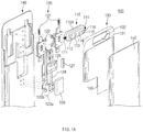
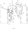
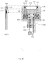
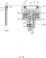
- the slide portion 130 may include an opening 131, a gear groove 132, and the movement member coupling portion 133.
- the opening 131 may be formed at a part (e.g., at the top end of the slide portion 130) of the slide portion 130.
- the opening 131 may be formed to correspond to the size of the camera module unit 110.
- the camera module unit 110 may be disposed in the opening 131.
- the camera module unit 110 may rotate inside the opening 131 about the pinion gear 111.
- the pinion gear 111 may be disposed in the gear groove 132.
- the pinion gear 111 may rotate inside the gear groove 132.
- the movement member coupling portion 133 may be coupled to the movement member 125. Accordingly, the slide portion 130 may move depending on the movement (e.g., upward and downward movement) of the movement member 125.
- the slide portion 130 may include a gear guide home 134.
- the rack gear 121 may be disposed to correspond to the gear guide home 134.
- the movement radius of the rack gear 121 may be determined by the gear guide home 134.
- the display unit 140 may include the display 141.
- the display 141 may be coupled to a touch sensing circuit, a pressure sensor which may measure the intensity (or pressure) of a touch, and/or a digitizer detecting a magnetic stylus pen or may be positioned adjacent thereto.
- at least part of the sensor module (not shown), and/or at least part of the key input device (not illustrated) may be disposed in a part of the display 141.
- the camera may not be disposed in the display 141, and thus the size of the display 141 may be increased on the front surface of the electronic device 100.
- the rear cover 150 may cover a part of the slide portion 130.
- the opening 131 may be formed at a part of the slide portion 130 (e.g., at the top end of the slide portion 130) that is not covered by the rear cover 150.
- the slide portion 130 may slide up and down between the display unit 140 and the rear cover 150.
- the rear cover 150 may be formed by coated or colored glass, ceramic, polymer, metal (e.g., aluminum, stainless steel (STS), or magnesium), or a combination of at least two of the materials.
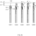
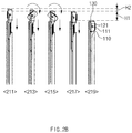
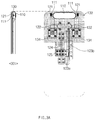
- the camera module unit 110, the rack gear 121, and the slide portion 130 may perform upward movement based on a user input.
- the camera module unit 110, the rack gear 121, and the slide portion 130 may move by a first movement distance H1.
- the rack gear 121 may be fixed by a cleek (e.g., the cleek 122).
- the camera module unit 110 may perform a descending operation or a rotation operation, based on a user input (e.g., rear shooting switching input or shooting termination input). As the camera module unit 110 rotates, at least one camera included in the camera module unit 110 may be used as a rear camera.
- a user input e.g., rear shooting switching input or shooting termination input.
- the camera module unit 110 may perform an ascending operation or a rotation operation, based on a user input (e.g., front shoot switching input or front shoot default application execution). As the camera module unit 110 rotates, at least one camera included in the camera module unit 110 may be used as a front camera (e.g., a self-camera).
- a user input e.g., front shoot switching input or front shoot default application execution.
- at least one camera included in the camera module unit 110 may be used as a front camera (e.g., a self-camera).
- the camera included in the camera module unit 110 may face the rear surface of the electronic device 100. At this time, the camera included in the camera module unit 110 may be used as a rear camera.
- the movement member 125 may be located at a reference location (e.g., the bottom end of the guide frame 124).
- the camera module unit 110, the rack gear 121, and the slide portion 130 may perform upward movement based on a user input.
- the motor 123a operates under control of a control circuit (e.g., the control circuit 126), and the rotation unit 123b may rotate in the first rotation direction by the motor 123a.
- the movement member 125 may slide up depending on the rotation of the rotation unit 123b.
- the slide portion 130 coupled to the movement member 125 moves upward and the rack gear 121 and the camera module unit 110, which are connected to the slide portion 130, may slide up together.
- the camera module unit 110, the rack gear 121, and the slide portion 130 may move by a first movement distance.
- the rack gear 121 may be fixed by the cleek 122.
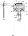
- the camera module unit 110 may perform upward movement and rotational movement.
- the rack gear 121 may be fixed by the cleek 122, and only the camera module unit 110 and the slide portion 130 may slide up.
- the camera module unit 110 and the slide portion 130 may slide up by a second movement distance.
- the pinion gear 111 may rotate while being interlocked with the rack gear 121. Accordingly, the camera module unit 110 may rotate.
- the camera included in the camera module unit 110 may face the front surface of the electronic device 100.
- the movement member 125 may be located at the top end of the guide frame 124.
- the camera included in the camera module unit 110 may be used as a front camera.
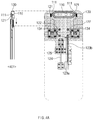
- the pinion gear 111 may rotate based on the length (or the number of gears) of the rack gear 121.
- the angle at which the pinion gear 111 rotates may vary depending on the length (or the number of gears) of the rack gear 121.
- the camera module unit 110 coupled with the pinion gear 111 may rotate by a specified angle (e.g., 10 to 270 degrees about the rear surface of the electronic device), depending on the length (or the number of gears) of the rack gear 121.
- the length (or the number of gears) of the rack gear 121 may be set such that the pinion gear 111 rotates by 180 degrees.
- the camera included in the camera module unit 110 may face the front surface of the electronic device 100.
- the camera included in the camera module unit 110 may face the front surface of the electronic device 100 by a previously entered user input (e.g., front shoot switching input or front shoot default application execution).
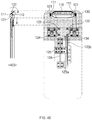
- the motor 123a operates under control of a control circuit (e.g., the control circuit 126), and the rotation unit 123b may rotate by the motor 123a in the direction opposite to first rotation direction.
- the movement member 125 may slide down depending on the rotation of the rotation unit 123b.
- the slide portion 130 coupled to the movement member 125 moves downward and the camera module unit 110 connected to the slide portion 130 may slide down.
- the camera module unit 110 and the slide portion 130 may move by a second movement distance.
- the rack gear 121 may be fixed by the cleek 122, and thus the rack gear 121 may not slide down.
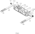
- the camera module unit 110 may include the camera housing 110A including the at least one camera device 112, 113, or 116, the flash 114, or the sensor module 115.
- the camera housing 110A may include a pinion gear 111 on at least one side surface.
- the pinion gear 111 may be formed integrally with the camera housing 110A.
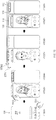
- the electronic device may move upwardly and rotate the camera module unit.
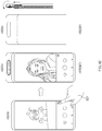
- the electronic device may receive a user input 621 (e.g., front shoot switching input).
- the electronic device may move upwardly and rotate the camera module unit.
- State 605 illustrates the front surface of an electronic device
- state 606 illustrates the rear surface of an electronic device.
- the electronic device may convert the camera included in the camera module unit to the front camera.
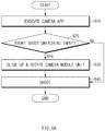
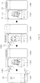
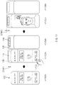
- an electronic device may execute a camera app.
- the electronic device may display the camera app screen depending on the user input 611 (e.g., touching a camera app icon).
- the electronic device may determine whether a rear shoot switching command is input. For example, when the rear shoot switching command is not input, the procedure may move to operation 760, and the electronic device may maintain a front camera and capture an image. When the rear shoot switching command is input, the electronic device may perform operation 750.
- the electronic device may move downwardly and rotate the camera module unit.
- the camera module unit may slide up to operate as the front camera.
- State 801 illustrates the front surface of an electronic device
- state 802 illustrates the rear surface of an electronic device.
- the electronic device may receive a user input 821 to terminate camera execution.
- the electronic device may move downwardly and rotate the camera module unit to change to the default location (e.g., the rear camera location).
- the upper end of the slide portion is aligned with the upper end of the display at the first location side by side, and the slide portion may protrude more than the upper portion of the housing at the second location.
- the electronic device may further include a motor and a rotation unit rotating by the motor.
- the movement member may perform a linear reciprocating movement along the guide frame by rotation of the rotation unit.
- control unit when the selfie shooting function is executed, may allow the slide portion to slide from the initial location to the second location and may allow the camera module unit from the first direction to the second direction.
- the electronic device 100 may determine whether a camera switching input is received. For example, when there is no camera switching input, the electronic device 100 may maintain the current state (e.g., the third state) depending on operation 935. When a camera switching input (e.g., the user input 1015 of FIG. 10 or camera app switching icon touch) is present, the state of the electronic device 100 may be switched to the second state depending on operation 915. Afterward, when the camera switching input is repeated, the state of the slide portion 130 may be repeatedly switched to the second state or the third state through the second stroke STRK2.
- a camera switching input e.g., the user input 1015 of FIG. 10 or camera app switching icon touch
- the state of the slide portion 130 may be switched through the first stroke STRK1 or the second stroke STRK2.
- the state of the slide portion 130 may be switched from the first state to the second state or may be switched from the second state to the first state, through the first stroke STRK1.
- the state of the slide portion 130 may be switched from the second state to the third state or may be switched from the third state to the second state, through the second stroke STRK2.
- the state of the slide portion 130 may be switched from the first state to the third state or may be switched from the third state to the first state, through the first stroke STRK1 and the second stroke STRK2.
- FIG. 11 illustrates a flowchart for operating an electronic device during camera shoot, according to various embodiments of the disclosure.
- the state of the slide portion 130 may be switched through the first stroke STRK1 or the second stroke STRK2.
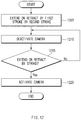
- FIG. 12 illustrates a flowchart for determining whether a camera is activated when a slide portion moves, according to various embodiments of the disclosure.
- a camera included in the camera module unit 110 may be deactivated in the progression of the first stroke STRK1 or the second stroke STRK2.
- the slide portion 130 may extend (e.g., extending upward from the rear surface of the display) or retract (e.g., extending and then returning to the original state), from at least part of the housing surrounding a display by the first stroke STRK1 or the second stroke STRK2.
- the state of the slide portion 130 may be switched from the first state to the second state or may be switched from the second state to the first state, through the first stroke STRK1.
- the state of the slide portion 130 may be switched from the second state to the third state or may be switched from the third state to the second state, through the second stroke STRK2.
- the state of the slide portion 130 may be switched from the first state to the third state or may be switched from the third state to the first state, through the first stroke STRK1 and the second stroke STRK2.
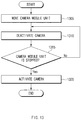
- FIG. 13 illustrates a flowchart for determining whether a camera is activated when a camera module unit moves, according to various embodiments of the disclosure.
- the camera included in the camera module unit 110 may be activated or deactivated, depending on the movement of the camera module unit 110.
- the camera when the camera module unit 110 is stopped (e.g., the second state or the third state), in operation 1320, the camera may be activated.
- the camera may be activated after the movement of the camera module unit 110 is stopped.
- the camera may be activated immediately before the movement of the camera module unit 110 is stopped.
- FIG. 14 illustrates a flowchart for operating an electronic device during camera shoot, according to various embodiments of the disclosure.
- FIG. 15 illustrates operating an electronic device during camera shoot, according to various embodiments of the disclosure.
- the electronic device 100 may determine whether a camera switching input is received. For example, when there is no camera switching input, the electronic device 100 may maintain the current state (e.g., the first state and rear shoot) depending on operation 1440. When a camera switching input (e.g., a user input 1513 of FIG. 15 or camera app switching icon touch) is present, the electronic device 100 may perform operation 1420.
- a camera switching input e.g., a user input 1513 of FIG. 15 or camera app switching icon touch
- the electronic device 100 may determine whether a camera switching input is received. For example, when there is no camera switching input, the electronic device 100 may maintain the current state (e.g., the third state) depending on operation 1440. When a camera switching input (e.g., camera app switching icon touch) is present, the electronic device 100 may perform operation 1430.
- a camera switching input e.g., camera app switching icon touch
- the state of the electronic device 100 may be switched from the third state to the second state.
- the state of the slide portion 130 may be switched from the third state to the second state through the second stroke STRK2.
- the camera module unit 110 may face the rear surface, and the camera may be activated (e.g., a rear shoot mode).
- the electronic device 100 may determine whether a camera switching input is received. For example, when there is no camera switching input, the electronic device 100 may maintain the current state (e.g., the second state) depending on operation 1440. When a camera switching input (e.g., camera app switching icon touch) is present, the state of the electronic device 100 may be switched to the third state depending on operation 1420. Afterward, when the camera switching input is repeated, the state of the slide portion 130 may be repeatedly switched to the second state or the third state through the second stroke STRK2.
- a camera switching input e.g., camera app switching icon touch
- the electronic device 100 may receive a camera app termination input (e.g., camera app termination icon touch).
- a camera app termination input e.g., camera app termination icon touch
- the state of the slide portion 130 may be switched to the first state regardless of the current state (e.g., the first state, the second state, or the third state).
- the camera module unit 110 may face the rear surface, and the camera may be deactivated.
- the electronic device 100 may verify the ambient illuminance of the electronic device.
- the electronic device 100 may activate the camera of the camera module unit 110 and may verify the ambient illuminance of the electronic device by using the camera.
- the electronic device 100 may verify illuminance by using a sensor other than a camera (e.g., an illuminance sensor).
- the electronic device 100 may perform operation 1620.
- the electronic device 100 may prevent the slide portion 130 from extending in the pants pocket or bag of the user.
- the electronic device 100 may move to the first state in response to the termination of a video call. Unlike the case of incoming a video call, the electronic device 100 may reduce the time used for the slide portion 130 of the electronic device 100 to be fully retracted, by moving from the third state to the first state.
- FIG. 18 illustrates a schematic diagram of a three-dimensional image capturing method, according to various embodiments of the disclosure.
- the electronic device 100 may obtain the three-dimensional image using a plurality of lenses disposed at the left side and the right side of the camera module unit 110.
- a plurality of lenses may be disposed spaced apart at regular intervals on the long axis of the camera module unit 110.
- the long axis of the camera module unit 110 may correspond to the width of the image
- the axis perpendicular to the long axis may correspond to the height of the image.
- the three-dimensional image obtained by the electronic device 100 using a plurality of lenses disposed on the left side and the right side may have a shape the height of which is greater than the width.
- FIG. 19 illustrates a tilting operation of a camera module unit, according to various embodiments of the disclosure.
- FIG. 20 illustrates a schematic diagram of an image capturing method using a tilting operation of a camera module unit, according to various embodiments of the disclosure.
- the electronic device 100 may rotate (e.g., tilt) the camera module unit 110 based on an input 2120 to the UI 2110. For example, when the input 2120 to move downwardly is received in the UI 2110, the electronic device 100 may tilt the camera module unit 110 such that the camera of the camera module unit 110 faces downwardly.
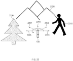
- the electronic device 100 may obtain a panorama image by rotating the camera of the camera module unit 110.
- the electronic device 100 may obtain an image (e.g., an image with an angle of view greater than 180 degrees) having an angle of view greater than the default angle of view of the camera, by obtaining an image while rotating the camera module unit 110.
- the electronic device 100 may obtain a plurality of images while rotating the camera module unit 110, and then may obtain a panorama image through performing post-processing (e.g., stitching) on the obtained plurality of images.
- post-processing e.g., stitching
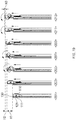
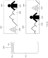
- the camera module unit 110 may obtain an image while rotating from the first direction 2201 in the order of the second direction 2202, the third direction 2203, the fourth direction 2204, and the fifth direction 2205.
- the electronic device 100 may obtain an image corresponding to the first direction 2201 by using the camera of the camera module unit 110 in the state 201 of FIG. 2 .
- the electronic device 100 may obtain an image corresponding to the fifth direction 2205 by using the camera of the camera module unit 110 in the state 209 of FIG. 2 .
- the first direction 2201 is the direction in which the rear surface of the electronic device 100 faces
- the fifth direction 2205 is the direction in which the front surface (e.g., the surface on which the display unit 140 is positioned) of the electronic device 100 faces.
- FIG. 25 illustrates a panorama images obtained by an electronic device, according to various embodiments of the disclosure.
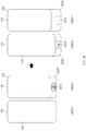
- reference numeral 2601 illustrates the front surface of the electronic device 100 in a state where the electronic device 100 is not extended (e.g., a retracted state); reference numeral 2602 illustrates the rear surface of the electronic device 100 in a state where the electronic device 100 is not extended.
- the display unit 140 may be positioned on the front surface of the electronic device 100.
- the rear cover 150 and a slide portion 2630 not covered by the rear cover 150 may be exposed on the rear surface of the electronic device 100.
- the slide portion 2630 of FIG. 26 may be included in the electronic device 100 together with the slide portion 130 of FIGS. 2 to 25 .
- the slide portion 2630 and the slide portion 130 are independent configurations, and the electronic device 100 may independently control the slide portion 2630 and the slide portion 130.
- the slide portion 2630 and the slide portion 130 may be configurations that are physically connected to each other. In this case, the slide portion 2630 may be retracted when the slide portion 130 extends upwardly; the slide portion 130 may be retracted when the slide portion 2630 extends downwardly.
- an electronic device may include a housing, a display (e.g., display unit 140), at least part of which is accommodated in the housing, a slide portion (e.g., the slide portion 130) including an opening (e.g., the opening 131) exposed to an outside and sliding with respect to the housing, and a camera module unit (e.g., the camera module unit 110) disposed at the opening and rotating with respect to the slide portion.
- a display e.g., display unit 140
- a slide portion e.g., the slide portion 130
- an opening e.g., the opening 131
- a camera module unit e.g., the camera module unit 110
- a camera included in the camera module unit may be configured to be deactivated, and, after the progression of the first stroke or the second stroke is completed, the camera included in the camera module unit may be configured to be activated.
- the slide portion when receiving an additional camera switching input, the slide portion may be configured to move back and forth between the second state and the third state, and the camera module unit may be configured to rotate back and forth between the first direction and the second direction.
- the housing may include a first surface (e.g., the display unit 140) facing a first direction (e.g., the direction of the display 141) and a second surface facing a second direction (e.g., the direction of the rear cover 150) opposite to the first direction.
- a first surface e.g., the display unit 140
- a second surface facing a second direction (e.g., the direction of the rear cover 150) opposite to the first direction.
- the camera structure may include a third surface forming a surface substantially extending from the second surface and at least one image sensor (e.g., a camera device 112, 113, or 116) rotating so as to face the second direction at the first location and to face the first direction at the second location, and when viewed from above the second surface at the second location, the first side may be interposed between the third side and the fifth side, and the sixth side may have a first distance from the third side.
- a third surface forming a surface substantially extending from the second surface and at least one image sensor (e.g., a camera device 112, 113, or 116) rotating so as to face the second direction at the first location and to face the first direction at the second location, and when viewed from above the second surface at the second location, the first side may be interposed between the third side and the fifth side, and the sixth side may have a first distance from the third side.
- image sensor e.g., a camera device 112, 113, or 116
- the memory may store instructions that, when executed, cause the processor to display a user interface of a camera application program (e.g., all apps associated with the execution of a camera) on the display, to display a first image from the image sensor on the user interface at the second location, while the first image is displayed, to receive a user input to change a direction of the camera, and to display a second image from the image sensor, on the user interface in a state of moving the camera structure from the second location to the first location by a second distance less than the first distance such that the image sensor faces the second direction in response to the reception of the user input, by using the driving mechanism.
- a camera application program e.g., all apps associated with the execution of a camera
- the second length may be greater than the first length
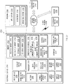
- the memory 2730 may store various data used by at least one component
- the input device 2750 may receive a command or data to be used by other component (e.g., the processor 2720) of the electronic device 2701, from the outside (e.g., a user) of the electronic device 2701.
- the input device 2750 may include, for example, a microphone, a mouse, a keyboard, or a digital pen (e.g., a stylus pen).
- the audio module 2770 may convert a sound into an electrical signal and vice versa. According to an embodiment, the audio module 2770 may obtain the sound via the input device 2750, or output the sound via the sound output device 2755 or a headphone of an external electronic device (e.g., an electronic device 2702) directly (e.g., wiredly) or wirelessly coupled with the electronic device 2701.
- an external electronic device e.g., an electronic device 2702
- directly e.g., wiredly
- wirelessly e.g., wirelessly
- the haptic module 2779 may convert an electrical signal into a mechanical stimulus (e.g., a vibration or a movement) or electrical stimulus which may be recognized by a user via his tactile sensation or kinesthetic sensation.
- the haptic module 2779 may include, for example, a motor, a piezoelectric element, or an electric stimulator.
- the power management module 2788 may manage power supplied to the electronic device 2701. According to one embodiment, the power management module 2788 may be implemented as at least part of, for example, a power management integrated circuit (PMIC).
- PMIC power management integrated circuit
- the communication module 2790 may include a wireless communication module 2792 (e.g., a cellular communication module, a short-range wireless communication module, or a global navigation satellite system (GNSS) communication module) or a wired communication module 2794 (e.g., a local area network (LAN) communication module or a power line communication (PLC) module).
- a wireless communication module 2792 e.g., a cellular communication module, a short-range wireless communication module, or a global navigation satellite system (GNSS) communication module
- GNSS global navigation satellite system
- wired communication module 2794 e.g., a local area network (LAN) communication module or a power line communication (PLC) module.
- LAN local area network
- PLC power line communication
- the signal or the power may then be transmitted or received between the communication module 2790 and the external electronic device via the selected at least one antenna.
- another component e.g., a radio frequency integrated circuit (RFIC)
- RFIC radio frequency integrated circuit
- the one or more external electronic devices receiving the request may perform the at least part of the function or the service requested, or an additional function or an additional service related to the request, and transfer an outcome of the performing to the electronic device 2701.
- the electronic device 2701 may provide the outcome, with or without further processing of the outcome, as at least part of a reply to the request.
- a cloud computing, distributed computing, or client-server computing technology may be used, for example.
- the electronic device may be one of various types of electronic devices.
- the electronic devices may include, for example, a portable communication device (e.g., a smartphone), a computer device, a portable multimedia device, a portable medical device, a camera, a wearable device, or a home appliance. According to an embodiment of the disclosure, the electronic devices are not limited to those described above.
Landscapes
- Engineering & Computer Science (AREA)
- Signal Processing (AREA)
- Multimedia (AREA)
- Human Computer Interaction (AREA)
- Computer Networks & Wireless Communication (AREA)
- Studio Devices (AREA)
Applications Claiming Priority (1)
| Application Number | Priority Date | Filing Date | Title |
|---|---|---|---|
| KR1020180151451A KR102106296B1 (ko) | 2018-11-29 | 2018-11-29 | 카메라를 포함하는 전자 장치 및 그것의 동작 방법 |
Publications (1)
| Publication Number | Publication Date |
|---|---|
| EP3661172A1 true EP3661172A1 (fr) | 2020-06-03 |
Family
ID=67997328
Family Applications (1)
| Application Number | Title | Priority Date | Filing Date |
|---|---|---|---|
| EP19196416.2A Withdrawn EP3661172A1 (fr) | 2018-11-29 | 2019-09-10 | Rotation de la caméra d'un téléphone mobile en fonction du mode de fonctionnement |
Country Status (3)
| Country | Link |
|---|---|
| US (1) | US10686971B1 (fr) |
| EP (1) | EP3661172A1 (fr) |
| KR (1) | KR102106296B1 (fr) |
Families Citing this family (16)
| Publication number | Priority date | Publication date | Assignee | Title |
|---|---|---|---|---|
| USD914633S1 (en) * | 2018-02-01 | 2021-03-30 | Beijing Xiaomi Mobile Software Co., Ltd. | Mobile phone |
| KR102481292B1 (ko) * | 2018-04-13 | 2022-12-26 | 삼성전자주식회사 | 플렉시블 디스플레이를 포함하는 전자 장치 |
| TWI698776B (zh) * | 2019-02-01 | 2020-07-11 | 仁寶電腦工業股份有限公司 | 具有升降式顯示器的電子裝置 |
| KR102925160B1 (ko) | 2019-03-28 | 2026-02-09 | 삼성디스플레이 주식회사 | 표시 장치 |
| KR102648987B1 (ko) * | 2019-04-09 | 2024-03-19 | 삼성전자 주식회사 | 회전 카메라를 포함하는 전자장치 |
| KR102660800B1 (ko) * | 2019-07-02 | 2024-04-26 | 삼성전자주식회사 | 회전 카메라를 포함하는 전자 장치 |
| KR102687671B1 (ko) * | 2019-07-26 | 2024-07-24 | 삼성전자주식회사 | 양 방향으로 슬라이드 가능한 전면 플레이트를 포함하는 전자 장치 |
| CN111427419B (zh) * | 2020-03-18 | 2021-11-23 | 维沃移动通信有限公司 | 翻转功能组件及电子设备 |
| EP4163760B1 (fr) | 2020-07-14 | 2025-03-26 | Samsung Electronics Co., Ltd. | Dispositif électronique comprenant un écran souple |
| EP4167050B1 (fr) | 2020-07-14 | 2025-04-16 | Samsung Electronics Co., Ltd. | Appareil électronique comprenant un écran souple |
| US11329682B2 (en) * | 2020-07-29 | 2022-05-10 | Motorola Solutions, Inc. | Portable communication device with non-touch user interface |
| CN111867312B (zh) * | 2020-07-31 | 2021-12-14 | 维沃移动通信有限公司 | 电子设备 |
| KR102754357B1 (ko) | 2020-08-04 | 2025-01-15 | 삼성디스플레이 주식회사 | 플렉시블 디스플레이를 포함하는 전자 장치 |
| CN113596203A (zh) * | 2021-07-19 | 2021-11-02 | 武汉华星光电半导体显示技术有限公司 | 显示装置 |
| WO2023191375A1 (fr) * | 2022-03-28 | 2023-10-05 | 삼성전자 주식회사 | Dispositif électronique comprenant un module d'entraînement et son procédé de commande |
| KR20260049707A (ko) * | 2023-08-24 | 2026-04-14 | 엘지전자 주식회사 | 비디오 카메라 |
Citations (5)
| Publication number | Priority date | Publication date | Assignee | Title |
|---|---|---|---|---|
| KR0151451B1 (ko) | 1994-10-31 | 1998-10-15 | 배순훈 | 움직임 벡터 복호화기 |
| EP1499094A1 (fr) * | 2003-07-16 | 2005-01-19 | Samsung Electronics Co., Ltd. | Terminal portable de type coulissant vers deux directions avec caméra |
| EP1551157A1 (fr) * | 2004-01-02 | 2005-07-06 | SK Teletech Co., Ltd. | Terminal de communication mobile du type coulissant avec une caméra rotative |
| CN207926665U (zh) * | 2018-02-09 | 2018-09-28 | 广东欧珀移动通信有限公司 | 移动终端 |
| CN207968576U (zh) * | 2018-02-09 | 2018-10-12 | 广东欧珀移动通信有限公司 | 手机 |
Family Cites Families (13)
| Publication number | Priority date | Publication date | Assignee | Title |
|---|---|---|---|---|
| US6192257B1 (en) * | 1998-03-31 | 2001-02-20 | Lucent Technologies Inc. | Wireless communication terminal having video image capability |
| US6637896B2 (en) * | 2001-10-31 | 2003-10-28 | Motorola, Inc. | Compact projection system and associated device |
| KR100551426B1 (ko) * | 2003-08-27 | 2006-02-09 | 주식회사 팬택앤큐리텔 | 카메라 연동장치를 갖는 슬라이딩방식 이동통신 단말기 |
| KR100703496B1 (ko) * | 2003-09-30 | 2007-04-03 | 삼성전자주식회사 | 슬라이딩 타입 휴대용 장치 |
| KR100593544B1 (ko) * | 2004-01-09 | 2006-06-28 | 주식회사 팬택 | 자동 개폐 슬라이드형 이동통신단말기 |
| KR20060010065A (ko) * | 2004-07-27 | 2006-02-02 | 주식회사 팬택 | 회전형 카메라를 구비한 이동통신단말기 |
| KR100652570B1 (ko) * | 2004-10-27 | 2006-12-07 | 엘지전자 주식회사 | 휴대용 단말기의 카메라 회전장치 |
| US7647081B2 (en) * | 2006-05-16 | 2010-01-12 | Nokia Corporation | Electronic device sliding mechanism |
| KR102165442B1 (ko) | 2013-02-01 | 2020-10-14 | 엘지전자 주식회사 | 이동 단말기 |
| US20160316046A1 (en) * | 2015-04-21 | 2016-10-27 | Jianhui Zheng | Mobile phone with integrated retractable image capturing device |
| US20170034319A1 (en) * | 2015-07-28 | 2017-02-02 | Ieon C. Chenn | Smartphone accessory with camera module |
| US10298728B2 (en) * | 2016-03-20 | 2019-05-21 | Case Cam LLC | Phone case with camera |
| US20170366652A1 (en) * | 2016-06-16 | 2017-12-21 | Eyes On Scope, LLC | Cell Phone Accessory Apparatus and System With Camera Functionality |
-
2018
- 2018-11-29 KR KR1020180151451A patent/KR102106296B1/ko active Active
-
2019
- 2019-03-07 US US16/296,143 patent/US10686971B1/en active Active
- 2019-09-10 EP EP19196416.2A patent/EP3661172A1/fr not_active Withdrawn
Patent Citations (7)
| Publication number | Priority date | Publication date | Assignee | Title |
|---|---|---|---|---|
| KR0151451B1 (ko) | 1994-10-31 | 1998-10-15 | 배순훈 | 움직임 벡터 복호화기 |
| EP1499094A1 (fr) * | 2003-07-16 | 2005-01-19 | Samsung Electronics Co., Ltd. | Terminal portable de type coulissant vers deux directions avec caméra |
| EP1551157A1 (fr) * | 2004-01-02 | 2005-07-06 | SK Teletech Co., Ltd. | Terminal de communication mobile du type coulissant avec une caméra rotative |
| CN207926665U (zh) * | 2018-02-09 | 2018-09-28 | 广东欧珀移动通信有限公司 | 移动终端 |
| CN207968576U (zh) * | 2018-02-09 | 2018-10-12 | 广东欧珀移动通信有限公司 | 手机 |
| EP3525431A1 (fr) * | 2018-02-09 | 2019-08-14 | Guangdong Oppo Mobile Telecommunications Corp., Ltd. | Téléphone mobile avec caméra |
| WO2019153835A1 (fr) * | 2018-02-09 | 2019-08-15 | Guangdong Oppo Mobile Telecommunications Corp., Ltd. | Appareil électronique |
Also Published As
| Publication number | Publication date |
|---|---|
| KR102106296B1 (ko) | 2020-05-04 |
| US20200177773A1 (en) | 2020-06-04 |
| US10686971B1 (en) | 2020-06-16 |
Similar Documents
| Publication | Publication Date | Title |
|---|---|---|
| US10686971B1 (en) | Electronic device including a camera capable of being a front camera and a rear camera and an operating method thereof | |
| US11550365B2 (en) | Foldable electronic device including sliding structure and method for controlling the same | |
| KR102857563B1 (ko) | 카메라 프리뷰 이미지를 제공하기 위한 전자 장치 및 그의 동작 방법 | |
| US11006024B2 (en) | Pop-up and rotational camera and electronic device including the same | |
| KR102848751B1 (ko) | 플렉서블 디스플레이의 촬영 안내 방법 및 장치 | |
| KR20200140609A (ko) | 폴더블 전자 장치 및 상기 폴더블 전자 장치에서 정보를 표시하는 방법 | |
| EP4068043B1 (fr) | Dispositif électronique pliable comprenant une caméra | |
| KR102913208B1 (ko) | 다양한 형태의 콘텐트를 표시하기 위한 폴더블 전자 장치 및 그의 동작 방법 | |
| EP3573329B1 (fr) | Dispositif électronique et procédé de commutation automatique en mode de capture panoramique | |
| KR102911825B1 (ko) | 전자 장치 및 그의 화면을 제어하는 방법 | |
| US12613950B2 (en) | Electronic device, and user interface method using biometric recognition in electronic device | |
| US11363712B2 (en) | Flexible printed circuit board and electronic device including the same | |
| US11889181B2 (en) | Electronic device having plurality of lenses where the device changes a visual object corresponding to a recommended lens | |
| KR20210032826A (ko) | 전자 장치 및 전자 장치의 정보 제공 방법 | |
| US20250080829A1 (en) | Electronic device and method for controlling camera | |
| KR20230059692A (ko) | 전자 장치 및 전자 장치에서 생체 인식을 이용한 사용자 인터페이스 방법 | |
| KR20250032734A (ko) | 전자 장치 및 카메라 제어 방법 | |
| KR20240159404A (ko) | 복수의 카메라들을 포함하는 전자 장치 및 전자 장치의 동작 방법 | |
| KR20240179020A (ko) | 원격 촬영을 위한 피드백 정보를 제공하는 방법 및 그 전자 장치 |
Legal Events
| Date | Code | Title | Description |
|---|---|---|---|
| PUAI | Public reference made under article 153(3) epc to a published international application that has entered the european phase |
Free format text: ORIGINAL CODE: 0009012 |
|
| STAA | Information on the status of an ep patent application or granted ep patent |
Free format text: STATUS: REQUEST FOR EXAMINATION WAS MADE |
|
| 17P | Request for examination filed |
Effective date: 20200331 |
|
| AK | Designated contracting states |
Kind code of ref document: A1 Designated state(s): AL AT BE BG CH CY CZ DE DK EE ES FI FR GB GR HR HU IE IS IT LI LT LU LV MC MK MT NL NO PL PT RO RS SE SI SK SM TR |
|
| AX | Request for extension of the european patent |
Extension state: BA ME |
|
| STAA | Information on the status of an ep patent application or granted ep patent |
Free format text: STATUS: EXAMINATION IS IN PROGRESS |
|
| 17Q | First examination report despatched |
Effective date: 20200630 |
|
| GRAP | Despatch of communication of intention to grant a patent |
Free format text: ORIGINAL CODE: EPIDOSNIGR1 |
|
| STAA | Information on the status of an ep patent application or granted ep patent |
Free format text: STATUS: GRANT OF PATENT IS INTENDED |
|
| INTG | Intention to grant announced |
Effective date: 20220921 |
|
| RIN1 | Information on inventor provided before grant (corrected) |
Inventor name: HAN, WOOSEUNG Inventor name: HONG, DOOHEE Inventor name: CHOI, JONGCHUL Inventor name: CHEONG, CHEOLHO Inventor name: LEE, SANGUK Inventor name: YOON, BYOUNGUK Inventor name: YOO, MINWOO |
|
| STAA | Information on the status of an ep patent application or granted ep patent |
Free format text: STATUS: THE APPLICATION IS DEEMED TO BE WITHDRAWN |
|
| 18D | Application deemed to be withdrawn |
Effective date: 20230202 |