EP3525484A1 - Dispositif de traitement de signal, procédé et programme - Google Patents
Dispositif de traitement de signal, procédé et programme Download PDFInfo
- Publication number
- EP3525484A1 EP3525484A1 EP17858223.5A EP17858223A EP3525484A1 EP 3525484 A1 EP3525484 A1 EP 3525484A1 EP 17858223 A EP17858223 A EP 17858223A EP 3525484 A1 EP3525484 A1 EP 3525484A1
- Authority
- EP
- European Patent Office
- Prior art keywords
- sound
- remote
- neighboring
- signal
- sound reproduction
- Prior art date
- Legal status (The legal status is an assumption and is not a legal conclusion. Google has not performed a legal analysis and makes no representation as to the accuracy of the status listed.)
- Withdrawn
Links
Images


Classifications
-
- G—PHYSICS
- G10—MUSICAL INSTRUMENTS; ACOUSTICS
- G10K—SOUND-PRODUCING DEVICES; METHODS OR DEVICES FOR PROTECTING AGAINST, OR FOR DAMPING, NOISE OR OTHER ACOUSTIC WAVES IN GENERAL; ACOUSTICS NOT OTHERWISE PROVIDED FOR
- G10K11/00—Methods or devices for transmitting, conducting or directing sound in general; Methods or devices for protecting against, or for damping, noise or other acoustic waves in general
- G10K11/18—Methods or devices for transmitting, conducting or directing sound
- G10K11/26—Sound-focusing or directing, e.g. scanning
- G10K11/34—Sound-focusing or directing, e.g. scanning using electrical steering of transducer arrays, e.g. beam steering
-
- H—ELECTRICITY
- H04—ELECTRIC COMMUNICATION TECHNIQUE
- H04R—LOUDSPEAKERS, MICROPHONES, GRAMOPHONE PICK-UPS OR LIKE ACOUSTIC ELECTROMECHANICAL TRANSDUCERS; ELECTRIC HEARING AIDS; PUBLIC ADDRESS SYSTEMS
- H04R3/00—Circuits for transducers
-
- G—PHYSICS
- G10—MUSICAL INSTRUMENTS; ACOUSTICS
- G10K—SOUND-PRODUCING DEVICES; METHODS OR DEVICES FOR PROTECTING AGAINST, OR FOR DAMPING, NOISE OR OTHER ACOUSTIC WAVES IN GENERAL; ACOUSTICS NOT OTHERWISE PROVIDED FOR
- G10K11/00—Methods or devices for transmitting, conducting or directing sound in general; Methods or devices for protecting against, or for damping, noise or other acoustic waves in general
- G10K11/18—Methods or devices for transmitting, conducting or directing sound
- G10K11/26—Sound-focusing or directing, e.g. scanning
- G10K11/34—Sound-focusing or directing, e.g. scanning using electrical steering of transducer arrays, e.g. beam steering
- G10K11/341—Circuits therefor
-
- G—PHYSICS
- G10—MUSICAL INSTRUMENTS; ACOUSTICS
- G10L—SPEECH ANALYSIS TECHNIQUES OR SPEECH SYNTHESIS; SPEECH RECOGNITION; SPEECH OR VOICE PROCESSING TECHNIQUES; SPEECH OR AUDIO CODING OR DECODING
- G10L21/00—Speech or voice signal processing techniques to produce another audible or non-audible signal, e.g. visual or tactile, in order to modify its quality or its intelligibility
- G10L21/02—Speech enhancement, e.g. noise reduction or echo cancellation
-
- H—ELECTRICITY
- H04—ELECTRIC COMMUNICATION TECHNIQUE
- H04R—LOUDSPEAKERS, MICROPHONES, GRAMOPHONE PICK-UPS OR LIKE ACOUSTIC ELECTROMECHANICAL TRANSDUCERS; ELECTRIC HEARING AIDS; PUBLIC ADDRESS SYSTEMS
- H04R1/00—Details of transducers, loudspeakers or microphones
- H04R1/20—Arrangements for obtaining desired frequency or directional characteristics
- H04R1/32—Arrangements for obtaining desired frequency or directional characteristics for obtaining desired directional characteristic only
- H04R1/40—Arrangements for obtaining desired frequency or directional characteristics for obtaining desired directional characteristic only by combining a number of identical transducers
- H04R1/403—Arrangements for obtaining desired frequency or directional characteristics for obtaining desired directional characteristic only by combining a number of identical transducers loud-speakers
-
- H—ELECTRICITY
- H04—ELECTRIC COMMUNICATION TECHNIQUE
- H04R—LOUDSPEAKERS, MICROPHONES, GRAMOPHONE PICK-UPS OR LIKE ACOUSTIC ELECTROMECHANICAL TRANSDUCERS; ELECTRIC HEARING AIDS; PUBLIC ADDRESS SYSTEMS
- H04R3/00—Circuits for transducers
- H04R3/04—Circuits for transducers for correcting frequency response
-
- H—ELECTRICITY
- H04—ELECTRIC COMMUNICATION TECHNIQUE
- H04R—LOUDSPEAKERS, MICROPHONES, GRAMOPHONE PICK-UPS OR LIKE ACOUSTIC ELECTROMECHANICAL TRANSDUCERS; ELECTRIC HEARING AIDS; PUBLIC ADDRESS SYSTEMS
- H04R3/00—Circuits for transducers
- H04R3/12—Circuits for transducers for distributing signals to two or more loudspeakers
-
- H—ELECTRICITY
- H04—ELECTRIC COMMUNICATION TECHNIQUE
- H04R—LOUDSPEAKERS, MICROPHONES, GRAMOPHONE PICK-UPS OR LIKE ACOUSTIC ELECTROMECHANICAL TRANSDUCERS; ELECTRIC HEARING AIDS; PUBLIC ADDRESS SYSTEMS
- H04R5/00—Stereophonic arrangements
- H04R5/02—Spatial or constructional arrangements of loudspeakers
-
- H—ELECTRICITY
- H04—ELECTRIC COMMUNICATION TECHNIQUE
- H04R—LOUDSPEAKERS, MICROPHONES, GRAMOPHONE PICK-UPS OR LIKE ACOUSTIC ELECTROMECHANICAL TRANSDUCERS; ELECTRIC HEARING AIDS; PUBLIC ADDRESS SYSTEMS
- H04R5/00—Stereophonic arrangements
- H04R5/04—Circuit arrangements, e.g. for selective connection of amplifier inputs/outputs to loudspeakers, for loudspeaker detection, or for adaptation of settings to personal preferences or hearing impairments
-
- H—ELECTRICITY
- H04—ELECTRIC COMMUNICATION TECHNIQUE
- H04S—STEREOPHONIC SYSTEMS
- H04S7/00—Indicating arrangements; Control arrangements, e.g. balance control
- H04S7/30—Control circuits for electronic adaptation of the sound field
- H04S7/302—Electronic adaptation of stereophonic sound system to listener position or orientation
Definitions
- the present technology relates to a signal processing device and a method, and a program, and relates particularly to a signal processing device and a method, and a program that are enabled to reproduce different sounds in a remote location and a neighboring location.
- Non-Patent Literature 1 a local sound field formation technology that is based on superdirective control using a parametric speaker.
- Non-Patent Literature 1 Kamakura et al., "Practical use of parametric speaker”, Acoustical Society of Japan Journal, vol.62, p.791-797, 2006 .
- Patent Literature 1 JP 2012-44572A
- the present technology has been devised in view of such a situation, and enables different sounds to be reproduced in a remote location and a neighboring location.
- a signal processing device includes: a remote filter unit configured to generate a remote sound reproduction signal for reproducing a sound in a remote audible region, by performing filter processing on a first sound source signal using a remote sound reproduction filter coefficient; and a neighboring filter unit configured to generate a neighboring sound reproduction signal for reproducing a sound in a neighboring audible region that is different from the remote audible region, by performing filter processing on a second sound source signal using a neighboring sound reproduction filter coefficient.
- the neighboring sound reproduction signal may be a signal for generating an evanescent wave.
- the signal processing device may further include a neighboring sound field processing unit configured to decide a decay rate of the evanescent wave in accordance with a boundary position of the remote audible region and the neighboring audible region.
- the neighboring filter unit may perform filter processing using the neighboring sound reproduction filter coefficient corresponding to the decided decay rate among a plurality of the neighboring sound reproduction filter coefficients.
- the signal processing device may further include a neighboring sound field processing unit configured to decide a position of a control point in accordance with a boundary position of the remote audible region and the neighboring audible region.
- the neighboring filter unit may perform filter processing using the neighboring sound reproduction filter coefficient corresponding to the decided position of the control point among a plurality of the neighboring sound reproduction filter coefficients.
- the signal processing device may further include a remote sound field processing unit configured to decide a position of a control point in accordance with a boundary position of the remote audible region and the neighboring audible region.
- the remote filter unit may perform filter processing using the remote sound reproduction filter coefficient corresponding to the decided position of the control point among a plurality of the remote sound reproduction filter coefficients.
- the remote sound reproduction signal may be a signal for generating a propagating wave.
- the signal processing device may further include: a remote sound field processing unit configured to decide a gain in accordance with a boundary position of the remote audible region and the neighboring audible region; and a remote gain adjustment unit configured to perform gain adjustment of the first sound source signal or the remote sound reproduction signal on a basis of the decided gain.
- a remote sound field processing unit configured to decide a gain in accordance with a boundary position of the remote audible region and the neighboring audible region
- a remote gain adjustment unit configured to perform gain adjustment of the first sound source signal or the remote sound reproduction signal on a basis of the decided gain.
- the signal processing device may further include: a neighboring sound field processing unit configured to decide a gain in accordance with a boundary position of the remote audible region and the neighboring audible region; and a neighboring gain adjustment unit configured to perform gain adjustment of the second sound source signal or the neighboring sound reproduction signal on a basis of the decided gain.
- a neighboring sound field processing unit configured to decide a gain in accordance with a boundary position of the remote audible region and the neighboring audible region
- a neighboring gain adjustment unit configured to perform gain adjustment of the second sound source signal or the neighboring sound reproduction signal on a basis of the decided gain.
- the first sound source signal and the second sound source signal may be signals for reproducing sounds of mutually different pieces of content.
- the signal processing device may further include: a speaker array configured to reproduce a sound on a basis of a signal obtained by synthesizing the remote sound reproduction signal and the neighboring sound reproduction signal.
- the signal processing device may further include: a first speaker array configured to reproduce a sound on a basis of the remote sound reproduction signal; and a second speaker array configured to reproduce a sound on a basis of the neighboring sound reproduction signal.
- a sound that is based on the remote sound reproduction signal may be reproduced at a timing different from a timing of a sound that is based on the neighboring sound reproduction signal.
- a sound that is based on the remote sound reproduction signal may be a sound for masking of a sound that is based on the neighboring sound reproduction signal.
- the signal processing device may further include: a sound field boundary control unit configured to decide a boundary position of the remote audible region and the neighboring audible region on a basis of a position of a listener in a space.
- a sound field boundary control unit configured to decide a boundary position of the remote audible region and the neighboring audible region on a basis of a position of a listener in a space.
- a signal processing method or a program includes the steps of: generating a remote sound reproduction signal for reproducing a sound in a remote audible region, by performing filter processing on a first sound source signal using a remote sound reproduction filter coefficient; and generating a neighboring sound reproduction signal for reproducing a sound in a neighboring audible region that is different from the remote audible region, by performing filter processing on a second sound source signal using a neighboring sound reproduction filter coefficient.
- a remote sound reproduction signal for reproducing a sound in a remote audible region is generated, by performing filter processing on a first sound source signal using a remote sound reproduction filter coefficient; and a neighboring sound reproduction signal for reproducing a sound in a neighboring audible region that is different from the remote audible region is generated, by performing filter processing on a second sound source signal using a neighboring sound reproduction filter coefficient.
- different sounds can be reproduced in a remote location and a neighboring location.
- the present technology enables different sounds to be reproduced in a remote location and a neighboring location using a speaker array.
- two sound fields are simultaneously formed by one speaker array obtained by linearly arranging a plurality of speakers, for example.
- a sound field (hereinafter, will also be referred to as a neighboring sound reproduction sound field) in which a sound can be heard only in a speaker array neighboring region
- a sound field (hereinafter, will also be referred to as a remote sound reproduction sound field) in which a sound can be heard even in a remote location distant from the speaker array are simultaneously formed by the speaker array.
- the neighboring sound reproduction sound field is formed by reproducing a sound on the basis of a neighboring sound reproduction signal for generating an evanescent wave, for example.
- the evanescent wave is a wave having such a property that a sound pressure exponentially decays by distance in a direction vertical to the speaker array.
- the neighboring sound reproduction sound field that is based on such an evanescent wave is a sound field in which a sound pressure sufficient for hearing is maintained only in the neighborhood of the speaker array, and a sound pressure steeply decays in a remote location.
- the remote sound reproduction sound field is formed by reproducing a sound on the basis of a remote sound reproduction signal for generating a propagating wave propagating to a remote location, such as a planar wave and a spherical wave. Note that, hereinafter, the description will be continued assuming that the remote sound reproduction sound field is formed by a planar wave.
- the remote sound reproduction sound field that is formed by such a propagating wave is a sound field in which a sound pressure sufficient for hearing is maintained even in a remote location distant from the speaker array.
- a wave surface of a reproduced sound becomes as illustrated in FIG. 1 , for example.
- a longitudinal direction and a traverse direction indicate directions in a space, and contrasting density in a portion indicated by an arrow Q11 indicates amplitude of the wave surface of the reproduced sound.
- one linear speaker array is arranged at a position indicated by an arrow A11, and a sound (hereinafter, will also be referred to as a neighboring sound) that is based on a neighboring sound reproduction signal, and a sound (hereinafter, will also be referred to as a remote sound) that is based on a remote sound reproduction signal are simultaneously reproduced by the linear speaker array.
- a sound hereinafter, will also be referred to as a neighboring sound
- a sound hereinafter, will also be referred to as a remote sound
- the neighboring sound is an evanescent wave and the remote sound is a planar wave
- these waves become waves of different regions in a spatial spectrum, that is to say, a spatiotemporal spectrogram.
- these waves do not interfere with each other, and a listener can distinguish between the neighboring sound and the remote sound.
- a sound pressure at each position in the space becomes as indicated by an arrow Q12
- a linear speaker array neighborhood becomes an audible region LE11 of the neighboring sound
- a region existing at a position distant from the linear speaker array becomes an audible region LE12 of the remote sound.
- contrasting densities at respective positions in a portion indicated by an arrow Q12 indicate sound pressures at these positions.
- a direction vertical to a direction in which a plurality of speakers constituting the linear speaker array is arranged is denoted as a y direction
- a sound pressure of the neighboring sound and a sound pressure of the remote sound decay as illustrated in FIG. 2 , for example, with respect to the y direction.
- a vertical axis indicates a sound pressure
- a horizontal axis indicates a position in the y direction.
- a straight line L11 indicates a sound pressure of the neighboring sound at each position in the y direction, and a sound pressure indicated by the straight line L11 becomes 1/e y when a distance in the y direction from the linear speaker array is denoted by y.
- a curved line L12 indicates a sound pressure of the remote sound at each position in the y direction, and a sound pressure indicated by the curved line L12 becomes 1/y when a distance in the y direction from the linear speaker array is denoted by y.
- a region R11 in which the sound pressure of the neighboring sound is larger than that of the remote sound becomes the audible region LE11 illustrated in FIG. 1
- a region R12 in which the sound pressure of the remote sound is larger than that of the neighboring sound becomes the audible region LE12 illustrated in FIG. 1 .
- a listener can hear not only the neighboring sound but also the remote sound, but a sound pressure difference between the neighboring sound and the remote sound can be made sufficiently large. It is therefore possible to cause the listener to hear the remote sound sufficiently small.
- a decay of the neighboring sound is large, and the listener can only hear the remote sound.
- a boundary position of the region R11 and the region R12 that is to say, a position in the y direction at which the sound pressures of the neighboring sound and the remote sound become the same level (magnitude) will also be referred to as a sound field boundary position.
- FIG. 3 is a diagram illustrating a configuration example of an embodiment of a remote-neighborhood separate sound field formation device to which the present technology is applied.
- a remote-neighborhood separate sound field formation device 11 illustrated in FIG. 3 is a signal processing device that reproduces different sounds in a remote location and a neighboring location.
- the remote-neighborhood separate sound field formation device 11 includes a remote sound field processing unit 21, a gain adjustment unit 22, a filter unit 23, a neighboring sound field processing unit 24, a gain adjustment unit 25, a filter unit 26, an addition unit 27, and a speaker array 28.
- control information for controlling a boundary position of a neighboring sound reproduction sound field and a remote sound reproduction sound field that is to say, a sound field boundary position being a boundary position of an audible region of a neighboring sound and an audible region of a remote sound is supplied to the remote sound field processing unit 21 and the neighboring sound field processing unit 24.
- control information is assumed to be listener position information indicating a position of a listener in a space, boundary position information indicating a position of a sound field boundary, or the like.
- boundary position information may be manually-input information or predefined information.
- the remote sound field processing unit 21 decides a sound field boundary position on the basis of the supplied control information.
- the remote sound field processing unit 21 includes a sound field boundary control unit 41, a remote sound reproduction filter coefficient recording unit 42, and a filter coefficient selection unit 43.
- the sound field boundary control unit 41 decides a sound field boundary position on the basis of the supplied control information, decides a gain value for gain adjustment of the remote sound on the basis of the decision result, and supplies the decided gain value to the gain adjustment unit 22.
- a gain value for gain adjustment of the remote sound will also be specifically referred to as a remote sound gain value.
- the sound field boundary control unit 41 generates remote sound reproduction filter coefficient selection information for selecting an appropriate remote sound reproduction filter coefficient from among a plurality of remote sound reproduction filter coefficients recorded in the remote sound reproduction filter coefficient recording unit 42, on the basis of the decision result of the sound field boundary position, and supplies the generated remote sound reproduction filter coefficient selection information to the filter coefficient selection unit 43.
- the remote sound reproduction filter coefficient recording unit 42 prerecords a plurality of remote sound reproduction filter coefficients being acoustic filter coefficients for forming a remote sound reproduction sound field on a side more distant from the speaker array 28 than a predetermined sound field boundary position, and supplies the recorded remote sound reproduction filter coefficients to the filter coefficient selection unit 43.
- the filter coefficient selection unit 43 selects one remote sound reproduction filter coefficient from among the plurality of remote sound reproduction filter coefficients recorded in the remote sound reproduction filter coefficient recording unit 42, and supplies the selected remote sound reproduction filter coefficient to the filter unit 23.
- the gain adjustment unit 22 On the basis of the remote sound gain value supplied from the sound field boundary control unit 41, the gain adjustment unit 22 performs gain adjustment of a supplied sound source signal, and supplies the obtained sound source signal to the filter unit 23.
- the sound source signal supplied to the gain adjustment unit 22 is an acoustic signal of a time region for reproducing a remote sound.
- the filter unit 23 By performing filter processing on the sound source signal supplied from the gain adjustment unit 22, using the remote sound reproduction filter coefficient supplied from the filter coefficient selection unit 43, the filter unit 23 generates a remote sound reproduction signal, and supplies the generated remote sound reproduction signal to the addition unit 27.
- convolution processing of convoluting the sound source signal and the remote sound reproduction filter coefficient is performed as the filter processing.
- the neighboring sound field processing unit 24 decides a sound field boundary position on the basis of the supplied control information.
- the neighboring sound field processing unit 24 includes a sound field boundary control unit 51, a neighboring sound reproduction filter coefficient recording unit 52, and a filter coefficient selection unit 53.
- the sound field boundary control unit 51 decides a sound field boundary position on the basis of the supplied control information, decides a gain value for gain adjustment of the neighboring sound on the basis of the decision result, and supplies the decided gain value to the gain adjustment unit 25.
- a gain value for gain adjustment of the neighboring sound will also be specifically referred to as a neighboring sound gain value.
- the sound field boundary control unit 51 generates neighboring sound reproduction filter coefficient selection information for selecting an appropriate neighboring sound reproduction filter coefficient from among a plurality of neighboring sound reproduction filter coefficients recorded in the neighboring sound reproduction filter coefficient recording unit 52, on the basis of the decision result of the sound field boundary position, and supplies the generated neighboring sound reproduction filter coefficient selection information to the filter coefficient selection unit 53.
- the neighboring sound reproduction filter coefficient recording unit 52 prerecords the plurality of neighboring sound reproduction filter coefficients being acoustic filter coefficients for forming a neighboring sound reproduction sound field on a side closer to the speaker array 28 than the predetermined sound field boundary position, and supplies the recorded neighboring sound reproduction filter coefficients to the filter coefficient selection unit 53.
- the filter coefficient selection unit 53 selects one neighboring sound reproduction filter coefficient from among the plurality of neighboring sound reproduction filter coefficients recorded in the neighboring sound reproduction filter coefficient recording unit 52, and supplies the selected neighboring sound reproduction filter coefficient to the filter unit 26.
- the gain adjustment unit 25 On the basis of the neighboring sound gain value supplied from the sound field boundary control unit 51, the gain adjustment unit 25 performs gain adjustment of a supplied sound source signal, and supplies the obtained sound source signal to the filter unit 26.
- the sound source signal supplied to the gain adjustment unit 25 is an acoustic signal of a time region for reproducing a neighboring sound.
- the sound source signal supplied to the gain adjustment unit 22 and the sound source signal supplied to the gain adjustment unit 25 are signals for reproducing sounds of mutually different pieces of content, but these sound source signals may be the same signals.
- the filter unit 26 By performing filter processing on the sound source signal supplied from the gain adjustment unit 25, using the neighboring sound reproduction filter coefficient supplied from the filter coefficient selection unit 53, the filter unit 26 generates a neighboring sound reproduction signal, and supplies the generated neighboring sound reproduction signal to the addition unit 27.
- convolution processing of convoluting the sound source signal and the neighboring sound reproduction filter coefficient is performed as the filter processing.
- the addition unit 27 generates a speaker drive signal for simultaneously reproducing a neighboring sound and a remote sound, by adding the remote sound reproduction signal supplied from the filter unit 23 and the neighboring sound reproduction signal supplied from the filter unit 26, and supplies the generated speaker drive signal to the speaker array 28.
- the speaker drive signal is generated by synthesizing the remote sound reproduction signal and the neighboring sound reproduction signal.
- the speaker array 28 is a speaker array obtained by arranging a plurality of speakers, such as a linear speaker array, a planar speaker array, an annular speaker array, or a spherical speaker array, for example, and reproduces a neighboring sound and a remote sound on the basis of the speaker drive signal supplied from the addition unit 27.
- a plurality of speakers such as a linear speaker array, a planar speaker array, an annular speaker array, or a spherical speaker array, for example, and reproduces a neighboring sound and a remote sound on the basis of the speaker drive signal supplied from the addition unit 27.
- a center position of the speaker array 28 is regarded as an origin O of a three-dimensional orthogonal coordinate system.
- three axes of the three-dimensional orthogonal coordinate system are regarded as an x-axis, a y-axis, and a z-axis that pass through the origin O, and are orthogonal to one another.
- a direction of the x-axis that is to say, an x direction is assumed to be direction in which the speakers constituting the speaker array 28 is arranged.
- a direction of the y-axis that is to say, the y direction is assumed to be a direction vertical to the x direction, and a direction parallel to a direction in which sound waves are output from the speaker array 28, and a direction vertical to the x direction and the y direction is assumed to be a direction of the z-axis, that is to say, a z direction.
- the direction in which sound waves are output from the speaker array 28 is assumed to be a positive direction of the y direction.
- a position in a space that is to say, a vector indicating a position in a space is assumed to be also described as (x, y, z) using an x-coordinate, a y-coordinate, and a z-coordinate.
- the description will be continued assuming that the speaker array 28 is a linear speaker array.
- the same processing is performed and a sound field boundary position is decided.
- listener position information is assumed to be supplied as control information.
- the listener position information indicating a position of a listener in a space can be obtained by image recognition performed on an image shot by a camera, detection of the listener that is performed using a sensor, an input of position information that is performed by a user or the like, or the like.
- a sound field boundary position is decided in such a manner that the position of the listener that is indicated by the listener position information serving as control information is included in an audible region of a remote sound or a neighboring sound.
- a sound field boundary position is decided in such a manner that a region including the listeners present in the neighborhood of the speaker array 28 becomes an audible region of a neighboring sound.
- the audible region of the neighboring sound is made wider by moving the sound field boundary position to a position more distant in the y direction from the speaker array 28.
- a sound field boundary position may dynamically change during the reproduction of a neighboring sound or a remote sound, that is to say, during the reproduction of content.
- a position indicated by the boundary position information is regarded as a sound field boundary position.
- a remote sound gain value, a neighboring sound gain value, remote sound reproduction filter coefficient selection information, and neighboring sound reproduction filter coefficient selection information are obtained in accordance with the decision result.
- a sound field boundary position to be set when sound fields are actually formed is defined by a remote sound gain value, a neighboring sound gain value, a position of a control point used when a remote sound reproduction sound field is formed, a decay rate of an evanescent wave that is obtainable when a neighboring sound reproduction sound field is formed, and the like.
- the remote sound reproduction sound field and the neighboring sound reproduction sound field can be formed in such a manner that the decided position becomes a sound field boundary position.
- an arbitrary position can be set as a sound field boundary position.
- a sound field boundary position can be changed. In other words, control of a sound field boundary position can be performed.
- a sound pressure of the content B that is to say, a neighboring sound changes as indicated by a straight line L21, with respect to the y direction
- a sound pressure of the content A that is to say, a remote sound changes as indicated by a curved line L22.
- a vertical axis indicates a sound pressure
- a horizontal axis indicates a position in the y direction.
- a remote sound gain value is made larger, from such a state, for example, the sound pressure of the content A, that is to say, a remote sound changes as indicated by a curved line L23 with respect to the y direction.
- the sound pressure of the content A at each position in the y direction becomes larger by gain adjustment of the content A, and accordingly, the sound field boundary position is moved to a position closer to the speaker array 28.
- a sound field boundary position gets close to the speaker array 28 in accordance with an increase in the sound pressure of the content A.
- an intersection position of the curved line L23 and the straight line L21, that is to say, a position indicated by an arrow W21 becomes a sound field boundary position.
- a sound field boundary position also changes by performing gain adjustment of the content B.
- the gain of the content B is made larger, that is to say, when a neighboring sound gain value is made larger, a sound field boundary position gets away from the speaker array 28.
- a sound field boundary position to be set when a neighboring sound reproduction sound field and a remote sound reproduction sound field are simultaneously formed can be set to the decided sound field boundary position.
- the sound field boundary control unit 41 and the sound field boundary control unit 51 it is identified in advance that sound pressures of a remote sound and a neighboring sound become what level at each position in the y direction in a case where a remote sound reproduction filter coefficient and a neighboring sound reproduction filter coefficient that are prepared in advance are used.
- the straight line L21 and the curved line L22 are known.
- the sound field boundary control unit 41 and the sound field boundary control unit 51 can obtain, for a decided sound field boundary position, such a remote sound gain value or a neighboring sound gain value that the decided sound field boundary position becomes a sound field boundary position when sound fields are actually formed.
- gain adjustment may be performed using only either one of a remote sound gain value and a neighboring sound gain value, or gain adjustment may be performed using both of these in combination. For example, when gain adjustment is substantially performed using only a remote sound gain value, a neighboring sound gain value is set to 1.
- a sound field boundary position also changes by changing a position of a control point of a remote sound reproduction filter coefficient for forming a remote sound reproduction sound field.
- a control line including a control point group that is called a reference line and is parallel to a direction in which speakers constituting the speaker array are arranged, that is to say, the x direction here.
- a formed sound field can be matched an ideal sound field only on the control point.
- remote sound reproduction filter coefficient recording unit 42 remote sound reproduction filter coefficients for a plurality of control points, that is to say, for positions in the y direction of the control points are prerecorded, and among these, a remote sound reproduction filter coefficient of one predetermined control point position is selected and supplied to the filter unit 23.
- a sound field boundary position changes as illustrated in FIG. 6 , for example.
- a vertical axis indicates a sound pressure and a horizontal axis indicates a position in the y direction.
- a curved line L32 indicates a sound pressure of the content A, that is to say, a remote sound, at each position in the y direction.
- the straight line L31 and the curved line L32 respectively indicate decay states of the sound pressures of the content B and the content A with respect to the y direction.
- the sound pressure of the content A changes as indicated by a curved line L33 with respect to the y direction, and a sound field boundary position becomes a position indicated by an arrow W22.
- a control point of a remote sound reproduction sound field that is to say, a control point of a remote sound reproduction filter coefficient with respect to a decided sound field boundary position
- a sound field boundary position to be set when a neighboring sound reproduction sound field and a remote sound reproduction sound field are simultaneously formed can be set to the decided sound field boundary position.
- the sound field boundary control unit 41 and the sound field boundary control unit 51 can obtain, for a decided sound field boundary position, such a position of a control point of a remote sound reproduction filter coefficient that the decided sound field boundary position becomes a sound field boundary position when sound fields are actually formed.
- a sound field boundary position also changes by changing a sound pressure decay rate of a neighboring sound reproduction filter coefficient for forming a neighboring sound reproduction sound field, that is to say, a decay rate of an evanescent wave.
- neighboring sound reproduction filter coefficient recording unit 52 neighboring sound reproduction filter coefficients for respective combinations of control points and constants ⁇ indicating sound pressure decay rates in the y direction are prerecorded, and among these, one neighboring sound reproduction filter coefficient is selected and supplied to the filter unit 26.
- a sound field boundary position changes as illustrated in FIG. 7 , for example.
- a vertical axis indicates a sound pressure and a horizontal axis indicates a position in the y direction.
- a curved line L42 indicates a sound pressure of the content A, that is to say, a remote sound, at each position in the y direction.
- the straight line L41 and the curved line L42 respectively indicate decay states of the sound pressures of the content B and the content A with respect to the y direction.
- a value of a constant ⁇ of a neighboring sound reproduction filter coefficient with which the sound pressure indicated by the straight line L41 is obtained is assumed to be a1.
- the sound pressure of the content B changes as indicated by a straight line L43 with respect to the y direction, and a sound field boundary position becomes a position indicated by an arrow W32.
- a sound field boundary position to be set when a neighboring sound reproduction sound field and a remote sound reproduction sound field are simultaneously formed can be set to the decided sound field boundary position.
- the sound field boundary control unit 51 and the sound field boundary control unit 41 can obtain, for a decided sound field boundary position, such a constant ⁇ of a neighboring sound reproduction filter coefficient that the decided sound field boundary position becomes a sound field boundary position when sound fields are actually formed.
- a neighboring sound reproduction filter coefficient is prepared for each combination of a control point and a constant ⁇ indicating a sound pressure decay rate, but a sound field boundary position also changes by changing the control point of the neighboring sound reproduction filter coefficient. Accordingly, an appropriate control point may be decided in accordance with a sound field boundary position also for the neighboring sound reproduction filter coefficient.
- a sound field boundary position changes depending on a remote sound gain value, a neighboring sound gain value, a control point of a remote sound reproduction filter coefficient, and a control point and a constant ⁇ of a neighboring sound reproduction filter coefficient.
- the sound field boundary control unit 41 and the sound field boundary control unit 51 decide, for a decided sound field boundary position, an appropriate combination of a remote sound gain value, a neighboring sound gain value, a control point of a remote sound reproduction filter coefficient, and a control point and a constant ⁇ of a neighboring sound reproduction filter coefficient.
- some of a remote sound gain value, a neighboring sound gain value, a control point of a remote sound reproduction filter coefficient, a control point of a neighboring sound reproduction filter coefficient, and a constant ⁇ of a neighboring sound reproduction filter coefficient may be dynamically decided, and the remaining values may be predefined.
- each parameter such as a remote sound gain value
- an audible region of a remote sound or a neighboring sound needs to be provided on a side more distant from the speaker array 28 than a control point.
- the sound field boundary control unit 41 supplies, to the filter coefficient selection unit 43, information indicating a position of the decided control point of the remote sound reproduction filter coefficient, as remote sound reproduction filter coefficient selection information.
- the sound field boundary control unit 51 supplies, to the filter coefficient selection unit 53, information indicating a position of the decided control point and the decided constant ⁇ of the neighboring sound reproduction filter coefficient, as neighboring sound reproduction filter coefficient selection information.
- the remote sound reproduction filter coefficient recording unit 42 records remote sound reproduction filter coefficients for respective positions of a plurality of control points.
- the remote sound reproduction filter coefficient is assumed to be obtained in advance by a spectral division method (SDM).
- SDM spectral division method
- a sound field P (v, n tf ) in a three-dimensional free space is represented as indicated in the following formula (1).
- P v , n tf ⁇ ⁇ ⁇ ⁇ D v 0 , n tf G v , v 0 , n tf dx 0
- n tf denotes a time frequency index
- v denotes a vector indicating a position in a space
- v (x, y, z) is set.
- v 0 denotes a vector indicating a predetermined position on the x-axis
- v 0 (x 0 , 0, 0) is set.
- a position indicated by the vector v will also be referred to as a position v
- a position indicated by the vector v 0 will also be referred to as a position v 0 .
- D (v 0 , n tf ) denotes a drive signal of a secondary sound source
- G (v, v 0 , n tf ) denotes a transfer function between the position v and the position vo.
- the drive signal D (v 0 , n tf ) of the secondary sound source corresponds to a remote sound reproduction signal.
- n sf denotes a spatial frequency index
- a sound field P F (n sf , y, z, n tf ) of a spatial frequency domain is represented by a product of a drive signal D F (n sf , n tf ) and a transfer function G F (n sf , y, z, n tf ) of the spatial frequency domain.
- spatial frequency representation of a drive signal of a secondary sound source becomes as indicated in the following formula (3).
- D F n sf , n tf P F n sf , y , z , n tf G F n sf , y , z , n tf
- a point sound source model P ps (n sf , y ref , 0, n tf ) can be used as indicated in the following formula (5).
- S (n tf ) denotes a sound source signal of a sound to be reproduced
- j denotes an imaginary unit
- k x denotes a wave number in the x-axis direction.
- x ps and y ps respectively denote an x-coordinate and a y-coordinate indicating a position of the point sound source, co denotes an angular frequency
- c denotes a sound speed.
- G F (n sf , y ref , 0, n tf ) can be represented as indicated in the following formula (6).
- G F n sf , y ref , 0 , n tf ⁇ ⁇ j 4 H 0 2 ⁇ c 2 ⁇ k x 2 y ref , k x ⁇ ⁇ c 1 2 ⁇ ⁇ K 0 k x 2 ⁇ ⁇ c 2 y ref , ⁇ c ⁇ k x
- the drive signal D F (n sf , n tf ), that is to say, a spatial frequency spectrum D F (n sf , n tf ) of a remote sound reproduction signal is obtained.
- 1 denotes a speaker index for identifying a speaker constituting the speaker array 28, and indicating a position in the x direction of the speaker
- M ds denotes the number of samples of DFT.
- time frequency synthesis of the time frequency spectrum D (1, n tf ) is performed using inverse discrete Fourier transform (IDFT), and a speaker drive signal d (1, n d ) of each speaker of the speaker array 28 being a temporal signal is obtained.
- IDFT inverse discrete Fourier transform
- the speaker drive signal d (1, n d ) is calculated.
- the speaker drive signals d (1, n d ) of the respective speakers are remote sound reproduction signals.
- n d denotes a time index and M dt denotes the number of samples of IDFT.
- the speaker drive signal d (1, n d ) obtained in this manner represents a filter coefficient itself that is independent of a sound source.
- the remote sound reproduction filter coefficient hf (l, m) is obtained for each speaker identified by the speaker index 1 of the speaker array 28.
- remote sound reproduction filter coefficient recording unit 42 remote sound reproduction filter coefficients hf (l, m) of the plurality of respective control points are prerecorded.
- the filter coefficient selection unit 43 reads out, from the remote sound reproduction filter coefficient recording unit 42, a remote sound reproduction filter coefficient hf (l, m) of the same control point as a control point indicated by the remote sound reproduction filter coefficient selection information supplied from the sound field boundary control unit 41, and supplies the read remote sound reproduction filter coefficient hf (l, m) to the filter unit 23.
- a control point group becomes planar, but also in such a case, a remote sound reproduction filter coefficient can be obtained similarly to the case of using a secondary sound source on a straight line.
- the neighboring sound reproduction filter coefficient recording unit 52 records neighboring sound reproduction filter coefficients for respective combinations of positions of a plurality of control points and a plurality of constants ⁇ . These neighboring sound reproduction filter coefficients are filter coefficients of acoustic filters for generating evanescent waves decaying in the y direction, by the speaker array 28.
- Such neighboring sound reproduction filter coefficients are obtained in the following manner, for example.
- time Fourier transform F ( ⁇ ) becomes as indicated in the following formula (12).
- T t 1 2 ⁇ ⁇ ⁇ ⁇ ⁇ ⁇ T ⁇ ⁇ e j ⁇ ⁇ ⁇ t d ⁇ ⁇
- F ⁇ 2 T t ⁇ t 2 j ⁇ 2 T ⁇ ⁇
- j denotes an imaginary unit and co denotes an angular frequency.
- P (v, ⁇ ) denotes a sound field of the angular frequency co at the position v.
- ⁇ ( ⁇ - ⁇ pw ) denotes a delta function.
- a wave of the wave number k pw,y indicated on the upper row, that is to say, the upper side of this formula (17) represents a normal propagating wave
- a wave of the wave number k pw,y indicated on the lower row, that is to say, the lower side of Formula (17) represents an evanescent wave.
- G' (k x , y, z, ⁇ ) of the transfer function is represented as indicated in the following formula (21).
- G ′ k x , y , z , ⁇ ⁇ ⁇ j 4 H 0 2 ⁇ c 2 ⁇ k x 2 y 2 + z 2 for k x ⁇ ⁇ c 1 2 ⁇ ⁇ K 0 k x 2 ⁇ ⁇ c 2 y 2 + z 2 for k x > ⁇ c
- H 0 (2) denotes a Hankel function of the second kind and K 0 denotes a Bessel function.
- a spatial frequency spectrum D' (k x , ⁇ ) of a neighboring sound reproduction signal becomes as indicated in the following formula (22).
- D ′ k x , ⁇ 8 ⁇ 3 e ⁇ ⁇ y ref e ⁇ jk pw , z z K 0 ⁇ y ref ⁇ ⁇ ⁇ ⁇ pw ⁇ k x ⁇ k pw , x
- y ref denotes a position of a control point serving as a reference in the y direction.
- a time waveform d (x, t) of a neighboring sound reproduction signal that is to say, a speaker drive signal d (x, t) being a temporal signal is obtained as indicated in the following formula (24).
- d x , t 2 ⁇ ⁇ e ⁇ ⁇ y ref e ⁇ jk pw , z z K 0 ⁇ y ref e ⁇ jk pw , x x e ⁇ j ⁇ pw t
- m denotes a time index.
- the neighboring sound reproduction filter coefficient h n (l, m) is obtained by replacing x in the speaker drive signal d (x, t) indicated in Formula (24), with the index 1, and replacing t with a time index m.
- neighboring sound reproduction filter coefficient recording unit 52 neighboring sound reproduction filter coefficients h n (l, m) for respective combinations of positions y ref of a plurality of control points and a plurality of constants ⁇ are prerecorded.
- the filter coefficient selection unit 53 reads out, from the neighboring sound reproduction filter coefficient recording unit 52, a neighboring sound reproduction filter coefficient h n (l, m) of a control point and a constant ⁇ that are the same as a control point and a constant ⁇ that are indicated by the neighboring sound reproduction filter coefficient selection information supplied from the sound field boundary control unit 51, and supplies the read neighboring sound reproduction filter coefficient h n (l, m) to the filter unit 26.
- a sound source signal supplied from the gain adjustment unit 22 to the filter unit 23 and a sound source signal supplied from the gain adjustment unit 25 to the filter unit 26 are assumed to be described as sound source signals x (n) without specifically making a distinction.
- n in the sound source signal x (n) denotes a time index.
- filter coefficients h (l, m) are assumed to also be referred to as filter coefficients h (l, m).
- N denotes a filter length
- the speaker drive signal s (l, n) of each speaker that has been obtained in the filter unit 23 by such calculation of Formula (26) is a remote sound reproduction signal.
- the speaker drive signal s (l, n) of each speaker that has been obtained in the filter unit 26 by such calculation of Formula (26) is a neighboring sound reproduction signal.
- remote-neighborhood separate sound field formation processing performed by the remote-neighborhood separate sound field formation device 11 will be described with reference to a flowchart in FIG. 8 .
- step S11 the sound field boundary control unit 41 and the sound field boundary control unit 51 decide a sound field boundary position on the basis of supplied control information.
- the sound field boundary control unit 41 and the sound field boundary control unit 51 define, on the basis of a position of a listener that is indicated by listener position information supplied as the control information, an audible region of a neighboring sound and an audible region of a remote sound, and define a position between these audible regions as a sound field boundary position.
- the sound field boundary control unit 41 and the sound field boundary control unit 51 directly use, as a sound field boundary position, a position indicated by boundary position information supplied as the control information.
- step S12 the sound field boundary control unit 41 and the sound field boundary control unit 51 decide each parameter such as a remote sound gain value on the basis of the sound field boundary position decided in the process in step S11.
- the sound field boundary control unit 41 and the sound field boundary control unit 51 decide, as parameters, the respective values of a remote sound gain value, a neighboring sound gain value, a position of a control point of a remote sound reproduction filter coefficient, a position of a control point of a neighboring sound reproduction filter coefficient, and a constant ⁇ of a neighboring sound reproduction filter coefficient.
- values of some parameters may be set to predefined values, and values of remaining parameters may be decided on the basis of the sound field boundary position.
- values of remaining parameters may be decided on the basis of the sound field boundary position.
- a sound field boundary position and values of the respective parameters may be simultaneously decided while being mutually adjusted. In other words, the processes in steps S11 and S12 may be simultaneously performed.
- the sound field boundary control unit 41 supplies, to the gain adjustment unit 22, a remote sound gain value serving as a decided parameter, and supplies, to the filter coefficient selection unit 43, information indicating a position of a control point of a remote sound reproduction filter coefficient serving as a decided parameter, as remote sound reproduction filter coefficient selection information.
- the sound field boundary control unit 51 supplies, to the gain adjustment unit 25, a neighboring sound gain value serving as a decided parameter, and supplies, to the filter coefficient selection unit 53, information indicating a position of a control point and a constant ⁇ of a neighboring sound reproduction filter coefficient that serve as decided parameters, as neighboring sound reproduction filter coefficient selection information.
- step S13 the filter coefficient selection unit 43 and the filter coefficient selection unit 53 select filter coefficients.
- the filter coefficient selection unit 43 selects a remote sound reproduction filter coefficient of a control point that is indicated by the remote sound reproduction filter coefficient selection information supplied from the sound field boundary control unit 41. In other words, a remote sound reproduction filter coefficient corresponding to the position of the control point that is indicated by the remote sound reproduction filter coefficient selection information is selected.
- the filter coefficient selection unit 43 reads out the selected remote sound reproduction filter coefficient from the remote sound reproduction filter coefficient recording unit 42, and supplies the read remote sound reproduction filter coefficient to the filter unit 23.
- the filter coefficient selection unit 53 selects a neighboring sound reproduction filter coefficient of a position of a control point and a constant ⁇ that are indicated by the neighboring sound reproduction filter coefficient selection information supplied from the sound field boundary control unit 51. In other words, a neighboring sound reproduction filter coefficient corresponding to the position of the control point and the constant ⁇ that are indicated by the neighboring sound reproduction filter coefficient selection information is selected.
- the filter coefficient selection unit 53 reads out the selected neighboring sound reproduction filter coefficient from the neighboring sound reproduction filter coefficient recording unit 52, supplies the read neighboring sound reproduction filter coefficient to the filter unit 26.
- step S14 the gain adjustment unit 22 and the gain adjustment unit 25 perform gain adjustment of the supplied sound source signals.
- the gain adjustment unit 22 performs the gain adjustment by multiplying the supplied sound source signal by the remote sound gain value supplied from the sound field boundary control unit 41, and supplies the resultant sound source signal to the filter unit 23.
- the gain adjustment unit 25 performs the gain adjustment by multiplying the supplied sound source signal by the neighboring sound gain value supplied from the sound field boundary control unit 51, and supplies the resultant sound source signal to the filter unit 26.
- step S15 the filter unit 23 and the filter unit 26 perform filter processing on the sound source signals.
- the filter unit 23 generates a remote sound reproduction signal by convoluting the sound source signal supplied from the gain adjustment unit 22 and the remote sound reproduction filter coefficient supplied from the filter coefficient selection unit 43 by performing the above-described calculation of Formula (26), and supplies the generated remote sound reproduction signal to the addition unit 27.
- the filter unit 26 generates a neighboring sound reproduction signal by convoluting the sound source signal supplied from the gain adjustment unit 25 and the neighboring sound reproduction filter coefficient supplied from the filter coefficient selection unit 53 by performing the above-described calculation of Formula (26), and supplies the generated neighboring sound reproduction signal to the addition unit 27.
- a remote sound reproduction signal and a neighboring sound reproduction signal may be generated using sound source signals not having been subjected to gain adjustment, and gain adjustment may be performed on the remote sound reproduction signal and the neighboring sound reproduction signal.
- gain adjustment is performed by the gain adjustment unit 22 on a remote sound reproduction signal on the basis of a remote sound gain value
- gain adjustment is performed by the gain adjustment unit 25 on a neighboring sound reproduction signal on the basis of a neighboring sound gain value.
- step S16 the addition unit 27 generates a speaker drive signal by adding the remote sound reproduction signal supplied from the filter unit 23 and the neighboring sound reproduction signal supplied from the filter unit 26, and supplies the generated speaker drive signal to the speaker array 28.
- step S17 the speaker array 28 simultaneously reproduces a remote sound and a neighboring sound on the basis of the speaker drive signal supplied from the addition unit 27, and the remote-neighborhood separate sound field formation processing ends.
- a remote sound reproduction sound field and a neighboring sound reproduction sound field are formed in mutually different regions in a space.
- an audible region of a remote sound and an audible region of a neighboring sound are formed at mutually different positions.
- the remote-neighborhood separate sound field formation device 11 decides each parameter such as a remote sound gain value in accordance with a sound field boundary position, performs gain adjustment and filter processing in accordance with the decided parameters, and generates a speaker drive signal for reproducing a remote sound and a neighboring sound. In this manner, different sounds can be reproduced in a remote location and a neighboring location.
- FIG. 9 a remote-neighborhood separate sound field formation device is formed as illustrated FIG. 9 , for example.
- FIG. 9 portions corresponding to those in the case in FIG. 3 are denoted with the same reference numerals, and the description thereof will be appropriately omitted.
- a remote-neighborhood separate sound field formation device 81 illustrated in FIG. 9 includes the remote sound field processing unit 21, the gain adjustment unit 22, the filter unit 23, the neighboring sound field processing unit 24, the gain adjustment unit 25, the filter unit 26, the speaker array 28, and a speaker array 91.
- the sound field boundary control unit 41, the remote sound reproduction filter coefficient recording unit 42, and the filter coefficient selection unit 43 are provided, and in the neighboring sound field processing unit 24, the sound field boundary control unit 51, the neighboring sound reproduction filter coefficient recording unit 52, and the filter coefficient selection unit 53 are provided.
- the configuration of the remote-neighborhood separate sound field formation device 81 differs from the configuration of the remote-neighborhood separate sound field formation device 11 in FIG. 3 in that the addition unit 27 is not provided and the speaker array 91 is newly provided, and has the same configuration as that of the remote-neighborhood separate sound field formation device 11 in other points.
- a remote sound reproduction signal obtained in the filter unit 23 is supplied to the speaker array 28, and in the speaker array 28, a remote sound is reproduced on the basis of the remote sound reproduction signal.
- a neighboring sound reproduction signal obtained in the filter unit 26 is supplied to the speaker array 91.
- the speaker array 91 is a speaker array obtained by arranging a plurality of speakers, such as a linear speaker array, a planar speaker array, an annular speaker array, or a spherical speaker array, for example, and reproduces a neighboring sound on the basis of the neighboring sound reproduction signal supplied from the filter unit 26.
- the speaker array 28 and the speaker array 91 may be arranged at the same position in the y direction, or may be arranged at different positions in the y direction.
- a neighboring sound reproduction sound field can be formed not only by an evanescent wave, but also by a propagating wave such as a planar wave or a spherical wave.
- a neighboring sound reproduction filter coefficient can be set to a filter coefficient for forming a neighboring sound reproduction sound field using planar waves, spherical waves, or the like that is generated similarly to the case in a remote sound reproduction filter coefficient, for example.
- remote-neighborhood separate sound field formation processing performed by the remote-neighborhood separate sound field formation device 81 will be described with reference to a flowchart in FIG. 10 .
- step S45 the filter unit 23 supplies an obtained remote sound reproduction signal to the speaker array 28, and the filter unit 26 supplies an obtained neighboring sound reproduction signal to the speaker array 91.
- step S46 the speaker array 28 reproduces a remote sound on the basis of the remote sound reproduction signal supplied from the filter unit 23.
- step S47 the speaker array 91 reproduces a neighboring sound on the basis of the neighboring sound reproduction signal supplied from the filter unit 26.
- steps S46 and S47 are simultaneously performed.
- a remote sound reproduction sound field and a neighboring sound reproduction sound field are thereby formed in mutually different regions in a space.
- an audible region of a remote sound and an audible region of a neighboring sound are formed at mutually different positions.
- the remote-neighborhood separate sound field formation processing ends.
- the remote-neighborhood separate sound field formation device 81 decides each parameter such as a remote sound gain value in accordance with a sound field boundary position, performs gain adjustment and filter processing in accordance with the decided parameters, and generates a remote sound reproduction signal and a neighboring sound reproduction signal. Different sounds can be thereby reproduced in a remote location and a neighboring location.
- reproduction of a remote sound is performed at a timing at which reproduction of a neighboring sound is not performed.
- a remote sound may be reproduced when the sound volume of a neighboring sound is small.
- a sound source signal for reproducing a neighboring sound is also supplied to the filter unit 23, and the filter unit 23 detects a time when the sound volume of the neighboring sound is small, such as a time when amplitude of the sound source signal for reproducing the neighboring sound is almost 0, that is to say, a timing at which a neighboring sound is not reproduced. Then, at the timing at which a neighboring sound is not reproduced, the filter unit 23 supplies a remote sound reproduction signal to the speaker array 28, and causes the speaker array 28 to reproduce a remote sound.
- a remote sound can be reproduced when a neighboring sound is not reproduced, that is to say, when a neighboring sound does not sound, and even at a position at which a difference between a sound pressure of a neighboring sound and a sound pressure of a remote sound is small, a listener can be prevented from hearing a mixed sound of the remote sound and the neighboring sound.
- the speaker array 28 and the speaker array 91 may be arranged in the z direction, that is to say, arranged at positions with different heights, and reproduce sounds of mutually different pieces of content.
- two sounds having mutually different audible regions may be reproduced by one speaker array as described in the first embodiment.
- a remote sound and a neighboring sound are reproduced by the speaker array 28, and in addition, a remote sound and a neighboring sound are also reproduced by the speaker array 91, so that four sound fields having mutually different positions of audible regions in the z direction and the y direction can be formed.
- a sound field boundary position of the remote sound and the neighboring sound that are reproduced by the speaker array 28, and a sound field boundary position of the remote sound and the neighboring sound that are reproduced by the speaker array 91 can be set to different positions in the y direction. In other words, the sound field boundary positions can be independently controlled.
- a video may be presented in combination.
- a polarization plate or the like together with a display device above the speaker array 28
- different videos images can be presented by the display device to a listener existing in an audible region of a remote sound and a listener existing in an audible region of a neighboring sound.
- a listener existing in an audible region of a remote sound content including a video viewable from the inside of the audible region and the remote sound can be presented
- a listener existing in an audible region of a neighboring sound content including a video viewable from the inside of the audible region and the neighboring sound can be presented.
- different pieces of content each including a video and a voice can be presented.
- a remote sound may be used for masking of a neighboring sound.
- a remote sound can be used as a voice for masking of a neighboring sound.
- BGM having the same frequency band as a neighboring sound or the like is used as a remote sound, and the remote sound and the neighboring sound are simultaneously reproduced by the remote-neighborhood separate sound field formation device 11 or the remote-neighborhood separate sound field formation device 81.
- the neighboring sound can be thereby made almost-unheard on the outside of the audible region of the neighboring sound. In other words, leakage of the neighboring sound to the outside of the audible region can be reduced.
- the above-described series of processes may be performed by hardware or may be performed by software.
- a program forming the software is installed into a computer.
- the computer include a computer that is incorporated in dedicated hardware and a general-purpose computer that can perform various types of function by installing various types of program.
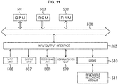
- FIG. 11 is a block diagram illustrating a configuration example of the hardware of a computer that performs the above-described series of processes with a program.
- a central processing unit (CPU) 501, read only memory (ROM) 502, and random access memory (RAM) 503 are mutually connected by a bus 504.
- an input/output interface 505 is connected to the bus 504. Connected to the input/output interface 505 are an input unit 506, an output unit 507, a recording unit 508, a communication unit 509, and a drive 510.
- the input unit 506 includes a keyboard, a mouse, a microphone, an image sensor, and the like.
- the output unit 507 includes a display, a speaker array, and the like.
- the recording unit 508 includes a hard disk, a non-volatile memory, and the like.
- the communication unit 509 includes a network interface, and the like.
- the drive 510 drives a removable recording medium 511 such as a magnetic disk, an optical disc, a magneto-optical disk, and a semiconductor memory.
- the CPU 501 loads a program that is recorded, for example, in the recording unit 508 onto the RAM 503 via the input/output interface 505 and the bus 504, and executes the program, thereby performing the above-described series of processes.
- programs to be executed by the computer can be recorded and provided in the removable recording medium 511, which is a packaged medium or the like.
- programs can be provided via a wired or wireless transmission medium such as a local area network, the Internet, and digital satellite broadcasting.
- programs can be installed into the recording unit 508 via the input/output interface 505. Programs can also be received by the communication unit 509 via a wired or wireless transmission medium, and installed into the recording unit 508. In addition, programs can be installed in advance into the ROM 502 or the recording unit 508.
- a program executed by the computer may be a program in which processes are chronologically carried out in a time series in the order described herein or may be a program in which processes are carried out in parallel or at necessary timing, such as when the processes are called.
- embodiments of the present disclosure are not limited to the above-described embodiments, and various alterations may occur insofar as they are within the scope of the present disclosure.
- the present technology can adopt a configuration of cloud computing, in which a plurality of devices shares a single function via a network and perform processes in collaboration.
- each step in the above-described flowcharts can be executed by a single device or shared and executed by a plurality of devices.
- a single step includes a plurality of processes
- the plurality of processes included in the single step can be executed by a single device or shared and executed by a plurality of devices.
- present technology may also be configured as below.
Landscapes
- Engineering & Computer Science (AREA)
- Physics & Mathematics (AREA)
- Acoustics & Sound (AREA)
- Signal Processing (AREA)
- Health & Medical Sciences (AREA)
- Otolaryngology (AREA)
- Multimedia (AREA)
- General Health & Medical Sciences (AREA)
- Audiology, Speech & Language Pathology (AREA)
- Human Computer Interaction (AREA)
- Quality & Reliability (AREA)
- Computational Linguistics (AREA)
- Circuit For Audible Band Transducer (AREA)
- Stereophonic System (AREA)
- Obtaining Desirable Characteristics In Audible-Bandwidth Transducers (AREA)
- Soundproofing, Sound Blocking, And Sound Damping (AREA)
Applications Claiming Priority (2)
| Application Number | Priority Date | Filing Date | Title |
|---|---|---|---|
| JP2016198750 | 2016-10-07 | ||
| PCT/JP2017/034240 WO2018066384A1 (fr) | 2016-10-07 | 2017-09-22 | Dispositif de traitement de signal, procédé et programme |
Publications (2)
| Publication Number | Publication Date |
|---|---|
| EP3525484A1 true EP3525484A1 (fr) | 2019-08-14 |
| EP3525484A4 EP3525484A4 (fr) | 2019-10-16 |
Family
ID=61830907
Family Applications (1)
| Application Number | Title | Priority Date | Filing Date |
|---|---|---|---|
| EP17858223.5A Withdrawn EP3525484A4 (fr) | 2016-10-07 | 2017-09-22 | Dispositif de traitement de signal, procédé et programme |
Country Status (7)
| Country | Link |
|---|---|
| US (2) | US10757505B2 (fr) |
| EP (1) | EP3525484A4 (fr) |
| JP (1) | JP7010231B2 (fr) |
| KR (1) | KR20190059905A (fr) |
| CN (1) | CN109792578A (fr) |
| BR (1) | BR112019006368A2 (fr) |
| WO (1) | WO2018066384A1 (fr) |
Families Citing this family (3)
| Publication number | Priority date | Publication date | Assignee | Title |
|---|---|---|---|---|
| WO2020036058A1 (fr) * | 2018-08-13 | 2020-02-20 | ソニー株式会社 | Dispositif et procédé de traitement de signaux et programme |
| US10764707B1 (en) * | 2019-01-29 | 2020-09-01 | Facebook Technologies, Llc | Systems, methods, and devices for producing evancescent audio waves |
| CN113497849A (zh) | 2020-03-20 | 2021-10-12 | 华为技术有限公司 | 一种声音的掩蔽方法、装置及终端设备 |
Family Cites Families (9)
| Publication number | Priority date | Publication date | Assignee | Title |
|---|---|---|---|---|
| JP4300194B2 (ja) * | 2005-03-23 | 2009-07-22 | 株式会社東芝 | 音響再生装置、音響再生方法および音響再生プログラム |
| JP4372081B2 (ja) * | 2005-10-25 | 2009-11-25 | 株式会社東芝 | 音響信号再生装置 |
| JP2011103543A (ja) * | 2009-11-10 | 2011-05-26 | Mitsubishi Electric Corp | 音声出力装置およびテレビ受像機 |
| KR101702330B1 (ko) * | 2010-07-13 | 2017-02-03 | 삼성전자주식회사 | 근거리 및 원거리 음장 동시제어 장치 및 방법 |
| JP5342521B2 (ja) * | 2010-08-23 | 2013-11-13 | 日本電信電話株式会社 | 局所再生方法、局所再生装置及びそのプログラム |
| US9245514B2 (en) | 2011-07-28 | 2016-01-26 | Aliphcom | Speaker with multiple independent audio streams |
| JP2013090038A (ja) * | 2011-10-14 | 2013-05-13 | Nippon Telegr & Teleph Corp <Ntt> | 特定エリア音響再生装置とフィルタ係数生成装置と、それらの方法とプログラム |
| US20130259254A1 (en) * | 2012-03-28 | 2013-10-03 | Qualcomm Incorporated | Systems, methods, and apparatus for producing a directional sound field |
| US10448161B2 (en) * | 2012-04-02 | 2019-10-15 | Qualcomm Incorporated | Systems, methods, apparatus, and computer-readable media for gestural manipulation of a sound field |
-
2017
- 2017-09-22 KR KR1020197008681A patent/KR20190059905A/ko not_active Ceased
- 2017-09-22 JP JP2018543840A patent/JP7010231B2/ja not_active Expired - Fee Related
- 2017-09-22 BR BR112019006368A patent/BR112019006368A2/pt not_active Application Discontinuation
- 2017-09-22 EP EP17858223.5A patent/EP3525484A4/fr not_active Withdrawn
- 2017-09-22 CN CN201780060680.8A patent/CN109792578A/zh active Pending
- 2017-09-22 US US16/338,014 patent/US10757505B2/en active Active
- 2017-09-22 WO PCT/JP2017/034240 patent/WO2018066384A1/fr not_active Ceased
-
2020
- 2020-07-14 US US16/928,174 patent/US20200344550A1/en not_active Abandoned
Also Published As
| Publication number | Publication date |
|---|---|
| US20200344550A1 (en) | 2020-10-29 |
| US20190238982A1 (en) | 2019-08-01 |
| EP3525484A4 (fr) | 2019-10-16 |
| JPWO2018066384A1 (ja) | 2019-07-18 |
| JP7010231B2 (ja) | 2022-01-26 |
| KR20190059905A (ko) | 2019-05-31 |
| CN109792578A (zh) | 2019-05-21 |
| WO2018066384A1 (fr) | 2018-04-12 |
| US10757505B2 (en) | 2020-08-25 |
| BR112019006368A2 (pt) | 2019-06-25 |
Similar Documents
| Publication | Publication Date | Title |
|---|---|---|
| US11310617B2 (en) | Sound field forming apparatus and method | |
| US9554227B2 (en) | Method and apparatus for processing audio signal | |
| KR101764175B1 (ko) | 입체 음향 재생 방법 및 장치 | |
| EP3823301B1 (fr) | Appareil de formation de champ sonore et procédé et programme | |
| CN104123948A (zh) | 声音处理设备、方法以及程序 | |
| CN105264911A (zh) | 音频设备 | |
| US10708686B2 (en) | Local sound field forming apparatus and local sound field forming method | |
| US20200344550A1 (en) | Signal processing device, method, and program stored on a computer-readable medium, enabling a sound to be reproduced at a remote location and a different sound to be reproduced at a location neighboring the remote location | |
| CN103811023A (zh) | 音频处理装置以及音频处理方法 | |
| EP3467818B1 (fr) | Dispositif de création de champ acoustique atténué localement, procédé et programme d'ordinateur correspondants | |
| US12363494B2 (en) | Signal processing apparatus and method | |
| JPWO2016056410A1 (ja) | 音声処理装置および方法、並びにプログラム | |
| EP3787311B1 (fr) | Dispositif de reproduction d'image sonore, procédé de reproduction d'image sonore et programme de reproduction d'image sonore | |
| JP2008092411A (ja) | 音響信号生成装置 | |
| Omoto et al. | Sound field reproduction applicable to noise control engineering | |
| CN121509895A (zh) | 空间渲染方法、装置、音频设备及计算机可读存储介质 | |
| CN120769218A (zh) | 声场扩展方法、音频设备及计算机可读存储介质 |
Legal Events
| Date | Code | Title | Description |
|---|---|---|---|
| STAA | Information on the status of an ep patent application or granted ep patent |
Free format text: STATUS: THE INTERNATIONAL PUBLICATION HAS BEEN MADE |
|
| PUAI | Public reference made under article 153(3) epc to a published international application that has entered the european phase |
Free format text: ORIGINAL CODE: 0009012 |
|
| STAA | Information on the status of an ep patent application or granted ep patent |
Free format text: STATUS: REQUEST FOR EXAMINATION WAS MADE |
|
| 17P | Request for examination filed |
Effective date: 20190507 |
|
| AK | Designated contracting states |
Kind code of ref document: A1 Designated state(s): AL AT BE BG CH CY CZ DE DK EE ES FI FR GB GR HR HU IE IS IT LI LT LU LV MC MK MT NL NO PL PT RO RS SE SI SK SM TR |
|
| AX | Request for extension of the european patent |
Extension state: BA ME |
|
| A4 | Supplementary search report drawn up and despatched |
Effective date: 20190918 |
|
| RIC1 | Information provided on ipc code assigned before grant |
Ipc: H04S 7/00 20060101ALN20190912BHEP Ipc: G10K 11/34 20060101AFI20190912BHEP Ipc: H04R 1/40 20060101ALI20190912BHEP Ipc: H04R 3/12 20060101ALI20190912BHEP |
|
| DAV | Request for validation of the european patent (deleted) | ||
| DAX | Request for extension of the european patent (deleted) | ||
| STAA | Information on the status of an ep patent application or granted ep patent |
Free format text: STATUS: EXAMINATION IS IN PROGRESS |
|
| 17Q | First examination report despatched |
Effective date: 20200605 |
|
| RIC1 | Information provided on ipc code assigned before grant |
Ipc: G10K 11/34 20060101AFI20210115BHEP Ipc: H04R 3/12 20060101ALI20210115BHEP Ipc: H04R 1/40 20060101ALI20210115BHEP Ipc: H04S 7/00 20060101ALN20210115BHEP |
|
| RAP3 | Party data changed (applicant data changed or rights of an application transferred) |
Owner name: SONY GROUP CORPORATION |
|
| STAA | Information on the status of an ep patent application or granted ep patent |
Free format text: STATUS: THE APPLICATION IS DEEMED TO BE WITHDRAWN |
|
| 18D | Application deemed to be withdrawn |
Effective date: 20210608 |