EP3525687B1 - Dispositif pour relier des tissus corporels - Google Patents
Dispositif pour relier des tissus corporels Download PDFInfo
- Publication number
- EP3525687B1 EP3525687B1 EP17800363.8A EP17800363A EP3525687B1 EP 3525687 B1 EP3525687 B1 EP 3525687B1 EP 17800363 A EP17800363 A EP 17800363A EP 3525687 B1 EP3525687 B1 EP 3525687B1
- Authority
- EP
- European Patent Office
- Prior art keywords
- tissue
- slider
- storage position
- staples
- rotor
- Prior art date
- Legal status (The legal status is an assumption and is not a legal conclusion. Google has not performed a legal analysis and makes no representation as to the accuracy of the status listed.)
- Active
Links
Images




Classifications
-
- A—HUMAN NECESSITIES
- A61—MEDICAL OR VETERINARY SCIENCE; HYGIENE
- A61B—DIAGNOSIS; SURGERY; IDENTIFICATION
- A61B17/00—Surgical instruments, devices or methods
- A61B17/068—Surgical staplers, e.g. containing multiple staples or clamps
-
- A—HUMAN NECESSITIES
- A61—MEDICAL OR VETERINARY SCIENCE; HYGIENE
- A61B—DIAGNOSIS; SURGERY; IDENTIFICATION
- A61B17/00—Surgical instruments, devices or methods
- A61B17/064—Surgical staples, i.e. penetrating the tissue
-
- A—HUMAN NECESSITIES
- A61—MEDICAL OR VETERINARY SCIENCE; HYGIENE
- A61B—DIAGNOSIS; SURGERY; IDENTIFICATION
- A61B17/00—Surgical instruments, devices or methods
- A61B17/068—Surgical staplers, e.g. containing multiple staples or clamps
- A61B17/0682—Surgical staplers, e.g. containing multiple staples or clamps for applying U-shaped staples or clamps, e.g. without a forming anvil
- A61B17/0684—Surgical staplers, e.g. containing multiple staples or clamps for applying U-shaped staples or clamps, e.g. without a forming anvil having a forming anvil staying above the tissue during stapling
-
- A—HUMAN NECESSITIES
- A61—MEDICAL OR VETERINARY SCIENCE; HYGIENE
- A61B—DIAGNOSIS; SURGERY; IDENTIFICATION
- A61B17/00—Surgical instruments, devices or methods
- A61B17/12—Surgical instruments, devices or methods for ligaturing or otherwise compressing tubular parts of the body, e.g. blood vessels or umbilical cord
- A61B17/128—Surgical instruments, devices or methods for ligaturing or otherwise compressing tubular parts of the body, e.g. blood vessels or umbilical cord for applying or removing clamps or clips
- A61B17/1285—Surgical instruments, devices or methods for ligaturing or otherwise compressing tubular parts of the body, e.g. blood vessels or umbilical cord for applying or removing clamps or clips for minimally invasive surgery
-
- A—HUMAN NECESSITIES
- A61—MEDICAL OR VETERINARY SCIENCE; HYGIENE
- A61B—DIAGNOSIS; SURGERY; IDENTIFICATION
- A61B17/00—Surgical instruments, devices or methods
- A61B17/00234—Surgical instruments, devices or methods for minimally invasive surgery
-
- A—HUMAN NECESSITIES
- A61—MEDICAL OR VETERINARY SCIENCE; HYGIENE
- A61B—DIAGNOSIS; SURGERY; IDENTIFICATION
- A61B17/00—Surgical instruments, devices or methods
- A61B17/00234—Surgical instruments, devices or methods for minimally invasive surgery
- A61B2017/00292—Surgical instruments, devices or methods for minimally invasive surgery mounted on or guided by flexible, e.g. catheter-like, means
- A61B2017/00296—Surgical instruments, devices or methods for minimally invasive surgery mounted on or guided by flexible, e.g. catheter-like, means mounted on an endoscope
-
- A—HUMAN NECESSITIES
- A61—MEDICAL OR VETERINARY SCIENCE; HYGIENE
- A61B—DIAGNOSIS; SURGERY; IDENTIFICATION
- A61B17/00—Surgical instruments, devices or methods
- A61B2017/00535—Surgical instruments, devices or methods pneumatically or hydraulically operated
- A61B2017/00539—Surgical instruments, devices or methods pneumatically or hydraulically operated hydraulically
Definitions
- the present invention relates to a device for connecting body tissues, comprising a head part which can be inserted into a body opening and has a longitudinal axis, wherein a plurality of tissue clamps are received in a storage position in the head part, which consist of a linear main section and two engagement sections projecting perpendicularly therefrom and which are each aligned in a first plane which is substantially perpendicular to the longitudinal axis.
- tissue staples that are inserted into the skin near the wound edges and then deformed to fix the wound edges together.
- Devices commonly called staplers have been developed to perform this procedure. Such devices are used, for example, in US 5 170 926 A , the EP 1 695 668 A or the EP 0 354 724 B.
- tissue clips are stacked in a magazine, similar to paper clips. Before use, the frontmost tissue clip is rotated into a position where it can be advanced and inserted into the skin.
- Other devices of this type are known from the WO2009/135005 A1 , US 5 564 615 A , DE 36 89 806 T2 and the EP 0 085 931 A2 known.
- the present invention relates to devices suitable for connecting sections of body tissue in the manner described above, with the difference that the device is sufficiently small and compact to be inserted into artificial or natural body openings in order to connect body tissue inside the body. It is therefore intended for use in endoscopic or laparoscopic procedures. The particular requirement is therefore to design the device with the smallest possible cross-section, to safely apply the required actuating forces, and to ensure high reliability, since direct visual and tactile control is not possible with this type of application.
- the object of the present invention is to provide a simple and easily applicable device with which it is possible to connect body tissue inside the body.
- a hydraulic cylinder and/or a piston rod are arranged at least partially inside the space which lies between the engagement sections of the tissue clamps in the storage position, and that the piston rod is firmly connected to the slide.
- the key feature is the hydraulic drive via a hydraulic cylinder, which allows the required force to be applied regardless of the distance to an operating element. Since the fabric clamps partially surround the hydraulic cylinder or piston rod in the storage position, significant space savings are achieved.
- the device can be designed to be particularly compact because the hydraulic cylinder is double-acting.
- two rotor elements are provided which are pivotable about an axis parallel to the main sections of the tissue clamps and which each have a support surface for an engagement section of a tissue clamp in order to rotate the latter from the storage position into a working position in which the tissue clamp is arranged in a further plane which is oriented substantially perpendicular to the first plane, and a slider is provided in order to advance the tissue clamp in the working position in the further plane and to deform it into a clamping position.
- the individual tissue staples are actively rotated by rotor elements from the plane in which they are stacked in the magazine (storage position) to the plane in which they are advanced to penetrate the body tissue (working position).
- the rotation takes place around an axis that is perpendicular to the longitudinal axis of the device and to the feed direction of the tissue staples.
- a slider performs both the task of advancing a tissue staple and the task of deforming it after it has penetrated the body tissue to create a secure connection. This allows the number of required components to be kept to a minimum, allowing the device to be designed to be particularly compact.
- a rotor spring engages each rotor element to lock its movement into two rotational positions, and preferably the rotor elements are connected to a shaft. This allows the drive of the rotor elements to be designed simply and with sufficient tolerances, since the exact angular position of the rotor elements is critical positions, namely the picking up and release of the tissue staples, is ensured by the locking mechanism.
- a particularly elegant way of ensuring the advancement of the tissue staples in the magazine and the necessary contact force on the rotor elements is that the tissue staples are pre-tensioned against the rotor element in the storage position by at least one storage spring via a storage carriage, whereby the storage spring is preferably attached to the shaft of the rotor elements.
- the storage spring is a leaf spring that is pre-tensioned in the wound position. It always strives to shorten the linear section parallel to the magazine and to wind itself around the shaft.
- the particular advantage of this solution is that the force applied to the storage carriage is independent of the position of the storage carriage, i.e. it remains essentially the same from the first to the last tissue staple.
- a particularly high degree of compactness can be achieved by driving the rotor elements by at least one connecting rod that is hinged to them and is preferably connected to the slide via a connecting slide. This makes it possible to drive both the slide and the rotor elements with a single drive element, thus eliminating the additional effort required for any synchronization of different drive elements.
- the rotor elements are each driven by a connecting rod and are preferably connected to the slide via a connecting slide. This ensures symmetrical force transmission.
- the elongated hole ensures that, in the first phase of the forward movement, only the slide is advanced, while the connecting rod pin slides backward in the elongated hole of the connecting slide, preventing the connecting rod and thus the rotor elements from moving.
- This phase ends when the pin reaches the rear end of the elongated hole.
- the connecting slide now carries the connecting rod with it, thus causing the rotor elements to rotate.
- a particularly preferred embodiment of the present invention provides that a slider is arranged on the side of the main sections of the tissue clips facing away from the engagement sections so as to be movable in the direction of the longitudinal axis, which slider has two lateral advance areas on its front end face, between which an essentially rectangular recess is provided, and that a retaining element is provided which engages in the recess of the slider in order to deform the linear main section of an intermediate tissue clip when the slider is advanced.
- the slider accomplishes both the advancement of the tissue staples and their deformation in a single movement.
- the force exerted on the respective tissue staple during advancement is exerted directly in the area of the engagement elements, so that these can be advanced against the resistance of the body tissue without initially causing deformation of the tissue staple. Only when the tissue staple has penetrated sufficiently deeply into the body tissue does the central portion of the main section of the tissue staple come into contact with the retaining element, so that the tissue staple is bent around the edges of the retaining element.
- this is achieved by arranging an ejection spring to strip a deformed tissue clip from the retaining element.
- Stripping is achieved particularly easily by the ejection spring extending into the slider's range of motion when force-free. Pushing the slider forward preloads the ejection spring, and retracting the slider releases the spring to strip the tissue staple.
- a particularly secure guidance of the tissue clamp can be achieved by providing a nose on the slider, which supports the tissue clamp to be advanced against the pretension of the ejection spring.
- a particularly compact and space-saving design of the device according to the invention can be achieved by having a plate-shaped slider and a plane of movement that lies in the region of the tips of the engaging portions of the tissue clips in the storage position, and particularly preferably substantially parallel to and at a constant distance from the main portions of the tissue clips in the storage position. This allows the slider and other components used to drive the slider to utilize the space created by the tissue clips present in the magazine in the storage position.
- a particularly efficient operation of the device is achieved in that the slider has a front position and a rear position, wherein in the front position a deformed tissue clamp is clamped between the slider and the retaining element, and in the rear position a tissue clamp rotated from the storage position into a working position perpendicular to it can be received.
- a particularly preferred embodiment of the invention provides at least one channel for receiving a holding instrument.
- Such known holding instruments can advantageously be used to hold tissue in place or manipulate its position in order to optimally insert the tissue clamps.
- two channels are provided, which preferably diverge slightly toward the front, and the angle between the channels is particularly preferably controllable. This allows for appropriately drawing in more distant tissue.
- the manipulation of body tissue can be made particularly flexible if the holding instruments can be controlled independently of each other.
- a particularly compact construction of the device according to the invention can be achieved in particular by arranging the channel preferably adjacent to the hydraulic cylinder and/or by arranging the channel between the side parts.
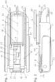
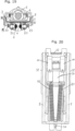
- Fig. 1 to Fig. 5 show the head part 100 of a device according to the invention, which comprises a tissue clamp 1 with a linear main section 2 and two parallel engagement sections 3 projecting perpendicularly therefrom (visible in Fig. 5 ) and deform.
- the device comprises a support element 4, on which two side parts 5, a hydraulic cylinder 6 with a piston rod 10 and a retaining element 22 are arranged. Tissue clamps 1 with their engagement sections 3 are located on the support element 4 in a storage position 7, which in Fig. 2 is partially shown.
- the side parts 5 each have a recess 39, the main part of which is rectangular and is intended to accommodate the engaging sections 3 of the tissue clips 1 in the storage position 7 and to guide them at the top and bottom. Furthermore, the respective rotor element 9 is accommodated in the recess 39.
- the tissue clamps 1 lie essentially in a stack, with the planes 7a, in which the main section 2 and the engagement sections 3 lie, being parallel to one another. Furthermore, the planes 7a lie essentially perpendicular to the axis 6a of the hydraulic cylinder 6, which simultaneously also represents the longitudinal axis of the device. This allows the tissue clamps 1 to be arranged in the storage position 7 such that the hydraulic cylinder 6 or the piston rod 10 can be located at least partially in the space formed between the engagement sections 3 of the tissue clamps 1 in the storage position 7. This enables a very compact and space-saving design.
- the tissue clamps 1 in the storage position 7 are pressed by a storage carriage 8 against two rotor elements 9, which are connected to a shaft 12.
- the necessary preload is generated by two storage springs 11. These are designed as unwound spiral springs, with one end attached to the shaft 12 and the other end to the storage carriage 8.
- Each of the two rotor elements 9 is rotatably mounted and has a support surface 13 with a support lug 16 for an engagement portion 3 of a tissue clamp 1 and a recess 14.
- a rotor spring 15 can engage in the recess 14 to enable locking and to define positions of the rotor elements 9.
- the rotor spring 15 is formed as an extension of the side part 5.
- the support surfaces 13 point in the direction of the tissue clamps 1 in the storage position 7.
- the storage carriage 8 presses a first tissue clamp 1 against the support surfaces 13.
- the rotor elements 9 can now be rotated by approximately 90°.
- the supported tissue clamp 1 is rotated by the support lugs 16 to reach a working position 29, in which it is arranged in a further plane 29a that is parallel to the longitudinal axis 6a.
- the first tissue clamp 1 is pressed against the support surfaces 13 by the storage carriage 8; during the second part of the rotation, the surface pressure is maintained by the rotor spring 15 to hold the first tissue clamp 1 in a defined position.
- the hydraulic cylinder 6 is in a retracted position at this time, and the slide 17 is therefore located behind the main section 2 of the first tissue clamp 1.
- the hydraulic cylinder 6 can now be extended.
- the slider 17 carries the first tissue clamp 1 with it.
- the position on the slider 17 is secured by an ejector spring 21 pressing the first tissue clamp 1 against the nose 18.
- the ejector springs 21 are increasingly pretensioned by the advance.
- the first tissue clamp 1 is now pressed against the retaining element 22, which is centrally positioned and adapted to the width of the recess 20 of the slider 17. This deforms the first tissue clamp 1 into a rectangle at the main section 2.
- the rotation of the rotor elements 9 is achieved via a connecting rod 23 articulated thereto, which has a first pin 30 that engages in an eccentric bore 31 of the respective rotor element 9.
- Each connecting slide 24 connected to the slide 17 has an elongated hole 25 into which a second pin 26 of the connecting rod 23 engages. The connection in an elongated hole 25 ensures that the rotation of the rotor elements 9 occurs in a second phase of the movement of the slide 17.
- Cover plates 32 are mounted laterally outside the side parts 5 to cover their recesses 33.
- the piston rod 10 is sealed by seals 34 against the hydraulic cylinder 6, which is mounted on the Support element 4 is attached.
- Hydraulic connections 36 and 37 serve to supply the hydraulic medium to control the device.
- 38 denotes a mounting bracket.
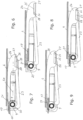
- Fig. 6 shows the initial state with hydraulic cylinder 6 and fully extended piston rod 10.
- the pin 26 is located in the extension-side stop 27 of the elongated hole 25, the support surface 13 of the rotor elements 9 is parallel to the longitudinal axis 6a.
- the slide 17 is in the fully extended position, in which a tissue staple 1 (not shown here) has just been ejected.
- the piston rod 10 is retracted, the slide 17 moves to the right in the illustration, and the connecting slide 24 connected to it also moves with it.
- no movement is transmitted to the connecting rod 23, since the pin 26 moves in the direction of the retraction-side stop 28 of the elongated hole 25 of the connecting slide 24.
- the retraction-side stop 28 is reached, and the connecting rod 23 is now moved along with the slide 17 and the connecting slide 24.
- the rotor elements 9 are rotated by approximately a right angle, so that a first tissue clip 1, which rests on the support surface 13 in the storage position, is moved from a Fig. 6 vertical position into a horizontal position in which it lies in the plane of the slider 17.
- the tissue clamp 1 resting on the support surfaces 13 is carried along by the support lugs 16 of the rotor elements 9. Since the slider 17 has already retracted behind the rotor elements 9 at this point in time, the movement path for the tissue clamp 1 is free.
- the ejector springs 21 are pretensioned via the tissue clamp 1 in the working position 29, whereby the lugs 18 on the slider 17 support the tissue clamp 1 at the bottom in the working position 29, so that the tissue clamp 1 is guided on both sides.
- the support of the tissue clamp 1 from below is removed, so that the ejector springs 21 press it downward and strip it from the retaining element 22.
- the working cycle can be stopped after reaching the Fig. 9 start again in the position shown.
- FIG. 10 to Fig. 13 Two different design variants of a rotor element 9 are shown.
- the first design variant, which is shown in the Fig. 10 and Fig. 11 shown corresponds to the version of the Fig. 1 to Fig. 9 used and illustrated rotor element 9.
- This first embodiment has a support surface 13 that forms part of a circular segment with respect to the circumference 43.
- a nose 13a is provided at one end to entrain the tissue clamp 1, which in its storage position rests with its engagement portion 3 against the support surface 13, during the rotation of the rotor element 9.
- the support surface 13 does not extend over the entire thickness of the rotor element 9.
- a web 40 remains on one side, which laterally guides the engagement portion 3 of the adjacent tissue clamp 1.
- a first recess 41 is provided in the area of this web 40, and a second recess 14 is formed in the circumference 43 at a right angle to it, as seen from the center of the rotor element 9.
- the two recesses 41, 14 serve to engage the rotor spring 15 and determine the end positions of the rotation of the rotor element 9.
- the eccentric bore 31 is used for rotation by the connecting rod 23.
- the bore 42 is intended for insertion onto the shaft 12.
- the support surface 13 extends over the entire thickness of the circumference 43.
- the lateral guidance is provided by the cover plates 32.
- a further contact surface 44 is provided on the circumference, preferably at right angles thereto, against which the tissue staples 1 rest in the storage position 7 when the support surface 13 is rotated into the ejection position (parallel to the longitudinal axis 6a).
- the contact surfaces 13 or the contact surface 44 which are supported by the storage springs, define 11 pressed engagement sections 3 of the tissue clamps 1 determine the end positions of the rotation of the rotor element 9. Recesses are therefore not required here.
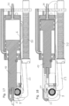
- Fig. 14 shows a longitudinal section of an embodiment of the device according to the invention using the rotor elements 9 of the Fig. 12 and Fig. 13
- This variant largely corresponds to the one in the Fig. 1 to Fig. 9 illustrated embodiment.
- the engagement section 3 of a first tissue clamp 1 on the support surface 13 is already in the working position 29.
- a further tissue clamp 1 rests with its engagement section 3 against the further support surface 44 and is pressed by the supply slide 8, so that the rotor element 9 is resiliently fixed in this position.
- the rotor element 9 is rotated back clockwise, although the supply slide 8, together with the tissue clamps 1 located in the supply position 7, must first be pushed back against the resistance of the supply springs 11.
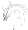
- FIG. 15 A first variant of the use of a device according to the invention is shown.
- the head part 100 is removably mounted on a conventional endoscope 101 with a bend 102 and is controlled via hydraulic hoses 103 and 104, which are inserted into a body opening parallel to the endoscope.
- Fig. 16 shows an alternative variant of the use of the device according to the invention, in which the head part 100 forms the tip of an independent flexible instrument 105. According to the usual design, this has at least one channel through which an endoscope 107 with a bend 102 can be inserted. The endoscope 107 is led out laterally with a separate bend 106 in order to be able to observe the clamping process.
- the version of the Fig. 17 and Fig. 18 differs from the variants described above in that two channels 50, 51 are provided below the hydraulic cylinder 6.
- the channels 50, 51 are directed towards the distal end directed outward, i.e., divergent, whereby the angle of divergence is preferably adjustable.
- When holding instruments are advanced through channels 50 and 51, they emerge slightly outward, whereby the variable extent is further increased by the distance to the tip, i.e., the space below the tissue clamps 1 in their storage position 7.
- the special design of the device makes it possible to arrange the channels 50 and 51 within the circular cross-section defined by the other components.
- the present invention makes it possible to connect tissue inside the body with tissue staples, wherein it is particularly advantageous that a plurality of tissue staples can be applied one after the other without the need to withdraw the device from the patient's body and then reinsert it.
Landscapes
- Health & Medical Sciences (AREA)
- Life Sciences & Earth Sciences (AREA)
- Surgery (AREA)
- Molecular Biology (AREA)
- Engineering & Computer Science (AREA)
- Biomedical Technology (AREA)
- Heart & Thoracic Surgery (AREA)
- Medical Informatics (AREA)
- Nuclear Medicine, Radiotherapy & Molecular Imaging (AREA)
- Animal Behavior & Ethology (AREA)
- General Health & Medical Sciences (AREA)
- Public Health (AREA)
- Veterinary Medicine (AREA)
- Reproductive Health (AREA)
- Vascular Medicine (AREA)
- Surgical Instruments (AREA)
Claims (14)
- Dispositif pour relier des tissus corporels à une partie (100) de tête, pouvant être insérés dans un orifice du corps, ayant un axe (6a) longitudinal, dans lequel dans la partie (100) de tête sont reçues une pluralité d'agrafes (1) pour du tissu en une position (7) de réserve, qui est constituée d'une partie (2) linéaire principale et de deux parties (3) de pénétration s'en éloignant perpendiculairement et qui sont dirigées respectivement dans un premier plan (7a), qui est sensiblement perpendiculaire à l'axe (6a) longitudinal, et comprenant un vérin (6) hydraulique et une tige (10) de piston, qui est assemblée fixement à un tiroir (17), caractérisé en ce que le vérin (6) hydraulique et/ou la tige (10) de piston sont disposés au moins en partie à l'intérieur de l'espace, qui se trouve entre les parties (3) de pénétration des agrafes (1) pour du tissus dans la position (7) de réserve et en ce qu'il est prévu deux éléments (9) de rotor, qui peuvent pivoter autour d'un axe parallèle aux parties (2) principales des agrafes (2) pour du tissu et qui ont chacun une surface (13) de support pour une partie (3) de pénétration d'une agrafe (1) pour du tissu, afin de faire tourner celle-ci de la position (7) de réserve à une position (29) de travail, dans laquelle l'agrafe (1) pour du tissu est disposée dans un autre plan (29a), qui est orienté sensiblement perpendiculairement au premier plan (7a), et en ce qu'il est prévu un tiroir (7), afin d'avancer dans l'autre plan (29a) l'agrafe (1) pour du tissu présente dans la position (29) de travail et la déformer en une position d'agrafage.
- Dispositif suivant la revendication 1, caractérisé en ce que le vérin (6) hydraulique est à double effet.
- Dispositif suivant l'une des revendications 1 à 2, caractérisé en ce que respectivement un ressort (15) de rotor attaque un élément (9) de rotor, afin d'exécuter, avec possibilité d'encliquetage, son déplacement dans deux positions en rotation et en ce que de préférence les éléments (9) de rotor sont assemblés entre eux par un arbre (12).
- Dispositif suivant l'une des revendications 1 à 3, caractérisé en ce que les éléments (9) de rotor sont entraînés par au moins une bielle (23), qui y est articulée et qui est en liaison avec le tiroir (17) de préférence par un tiroir (24) de liaison.
- Dispositif suivant la revendication 4, caractérisé en ce que le ou les tiroirs (24) de liaison est/sont assemblés d'une manière fixe au tiroir (17), et en ce que sur chaque tiroir (24) de liaison est disposé une boutonnière (25) dans laquelle pénètre un tenon (26) de la bielle (23).
- Dispositif suivant l'une des revendications 1 à 5, caractérisé en ce que les agrafes (1) pour du tissu sont guidées dans la position (7) de réserve dans des évidements (39) de parties (5) latérales.
- Dispositif suivant l'une des revendications 1 à 6, caractérisé en ce que le tiroir (17) est, du côté, non tourné vers les parties (3) de pénétration, des parties (2) principales des agrafes (1) pour du tissu, monté mobile dans la direction de l'axe (6a) longitudinal, lequel a du côté frontal avant deux parties (19) latérales d'avance, entre lesquelles est prévu un évidement (20), et en ce qu'il est prévu un élément (22) de retenu, qui pénètre dans l'évidement (20) du tiroir (17), afin de déformer, lors de l'avance du tiroir (17), la partie (2) principale linéaire d'une agrafe (1) pour du tissu interposée.
- Dispositif suivant l'une des revendications 1 à 7, caractérisé en ce que le tiroir (17) est constitué sous la forme d'une plaque et la partie de déplacement du tiroir (17) se trouve dans un autre plan (29a), qui se trouve dans la partie des pointes des parties (3) de pénétration des agrafes (1) pour du tissu dans la position (7) de réserve et, en particulier, de préférence sensiblement parallèlement à une distance constante des parties (2) principales des agrafes (1) pour du tissu dans la position (7) de réserve.
- Dispositif suivant l'une des revendications 1 à 8, caractérisé en ce que le tiroir (17) possède une position avant et une position arrière, dans lequel, dans la position avant, une agrafe (1) pour du tissu déformée est serrée entre le tiroir (17) et l'élément (22) de retenu et, dans la position arrière, une agrafe (1) pour du tissu, tournée de la position (7) de réserve à une position (29) de travail perpendiculaire à celle-ci, peut être reçue.
- Dispositif suivant l'une des revendications 1 à 9, caractérisé en ce que la partie (100) de tête est constituée en coiffe sur un endoscope (101) ou est assemblée d'une pièce avec un instrument (105) souple, qui a de préférence un conduit pour un endoscope (107).
- Dispositif suivant l'une des revendications 1 à 10, caractérisé en ce qu'il est prévu au moins un conduit (50, 51) de réception d'un instrument de maintien.
- Dispositif suivant la revendication 11, caractérisé en ce qu'il est prévu deux conduits (50, 51), qui s'écartent légèrement l'un de l'autre vers l'avant, dans lequel en particulier de préférence l'angle entre les conduits (50, 51) peut être commandé.
- Dispositif suivant l'une des revendications 11 ou 12, caractérisé en ce que les instruments de maintien peuvent être commandés indépendamment l'un de l'autre.
- Dispositif suivant l'une des revendication 11 à 13, caractérisé en ce que le conduit (50, 51) est disposé au voisinage du vérin (6) hydraulique, et/ou entre les parties (5) latérales et/ou dans la partie proximale de la partie (100) de tête.
Applications Claiming Priority (2)
| Application Number | Priority Date | Filing Date | Title |
|---|---|---|---|
| ATA50936/2016A AT518885B1 (de) | 2016-10-17 | 2016-10-17 | Vorrichtung zum verbinden von körpergeweben |
| PCT/AT2017/060267 WO2018071935A1 (fr) | 2016-10-17 | 2017-10-17 | Dispositif pour relier des tissus corporels |
Publications (3)
| Publication Number | Publication Date |
|---|---|
| EP3525687A1 EP3525687A1 (fr) | 2019-08-21 |
| EP3525687B1 true EP3525687B1 (fr) | 2025-05-14 |
| EP3525687C0 EP3525687C0 (fr) | 2025-05-14 |
Family
ID=67251150
Family Applications (1)
| Application Number | Title | Priority Date | Filing Date |
|---|---|---|---|
| EP17800363.8A Active EP3525687B1 (fr) | 2016-10-17 | 2017-10-17 | Dispositif pour relier des tissus corporels |
Country Status (2)
| Country | Link |
|---|---|
| US (1) | US11547402B2 (fr) |
| EP (1) | EP3525687B1 (fr) |
Family Cites Families (12)
| Publication number | Priority date | Publication date | Assignee | Title |
|---|---|---|---|---|
| AU540655B2 (en) | 1980-05-14 | 1984-11-29 | United States Surgical Corporation | Surgical stapler |
| DE3204522A1 (de) | 1982-02-10 | 1983-08-25 | B. Braun Melsungen Ag, 3508 Melsungen | Chirurgisches hautklammergeraet |
| US4691853A (en) * | 1985-12-30 | 1987-09-08 | Technalytics, Inc. | Surgical stapler |
| EP0354724B1 (fr) | 1988-08-09 | 1995-11-02 | Matsutani Seisakusho Co. Ltd., | Agrafeuse chirurgicale |
| US5170926A (en) | 1991-08-05 | 1992-12-15 | Edward Weck Incorporated | Surgical stapler |
| US5289963A (en) * | 1991-10-18 | 1994-03-01 | United States Surgical Corporation | Apparatus and method for applying surgical staples to attach an object to body tissue |
| US5601224A (en) * | 1992-10-09 | 1997-02-11 | Ethicon, Inc. | Surgical instrument |
| US5431323A (en) * | 1992-10-09 | 1995-07-11 | Ethicon, Inc. | Endoscopic surgical instrument with pivotable and rotatable staple cartridge |
| CA2117744A1 (fr) | 1993-10-14 | 1995-04-15 | David T. Green | Appareil pneumatique pour l'installation d'agraphes chirurgicales sur des tissus du corps |
| JP4712409B2 (ja) | 2005-02-28 | 2011-06-29 | マニー株式会社 | 医療用ステープラー |
| US8523040B2 (en) * | 2008-05-01 | 2013-09-03 | Ethicon Endo-Surgery, Inc. | Fastener and fastener applier having selective suture attachment |
| US20100276469A1 (en) | 2009-05-01 | 2010-11-04 | Barosense, Inc. | Plication tagging device and method |
-
2017
- 2017-10-17 EP EP17800363.8A patent/EP3525687B1/fr active Active
- 2017-10-17 US US16/342,486 patent/US11547402B2/en active Active
Also Published As
| Publication number | Publication date |
|---|---|
| US11547402B2 (en) | 2023-01-10 |
| US20190307447A1 (en) | 2019-10-10 |
| EP3525687A1 (fr) | 2019-08-21 |
| EP3525687C0 (fr) | 2025-05-14 |
Similar Documents
| Publication | Publication Date | Title |
|---|---|---|
| DE3249116C2 (de) | Chirurgisches Instrument | |
| DE19711288B4 (de) | Applikator zum Aufnehmen und Schließen einer chirurgischen Klammer | |
| DE3051048C2 (de) | Klemmenmagazin zur Verwendung mit einem chirurgischen Instrument | |
| DE3852446T2 (de) | Klammerpatrone und chirurgisches Klammerinstrument ohne Amboss. | |
| DE69722540T2 (de) | Chirurgischer Klemmmechanismus | |
| DE3587120T2 (de) | Vorrichtung zum anbringen von wundklammern. | |
| EP2012677B1 (fr) | Dispositif de pose d'éléments d'ancrage dans des tissus humains ou animaux | |
| DE69525083T2 (de) | Vorrichtung zum vorschub von ligaturklammern | |
| DE69116731T2 (de) | Vorrichtung zum Anbringen von Wundklammern | |
| DE69405807T2 (de) | Chirurgisches Klammergerät und Klammerpatrone | |
| DE69121189T2 (de) | Chirurgische Klammervorrichtung mit Verriegelungsmechanismus | |
| EP3136988B1 (fr) | Instrument médical à tige présentant différents écarts de position de stockage entre des éléments d'entraînement de clamps et des lames de retenue pour clamps | |
| DE2051991A1 (de) | Chirurgisches Gerat zum Klammernahen von Geweben | |
| DE1950759B2 (de) | Chirurgisches instrument | |
| DE2949389A1 (de) | Chirurgischer apparat zum zusammennaehen des hautgewebes | |
| DE1541175B1 (de) | Chirurgisches Instrument zum Naehen von hohlen Organen | |
| EP3010665B1 (fr) | Outil de pliage | |
| DE102021109025A1 (de) | Handstück für ein flexibles Endoskop oder für ein flexibles endoskopisches Instrument | |
| DE2654263A1 (de) | Chirurgisches naehgeraet zum zusammennaehen von geweben mit metallklammern | |
| EP2691022B1 (fr) | Dispositif piquant à élément rotatif | |
| EP3525687B1 (fr) | Dispositif pour relier des tissus corporels | |
| EP3525686B1 (fr) | Dispositif pour relier des tissus corporels | |
| AT518885B1 (de) | Vorrichtung zum verbinden von körpergeweben | |
| DE1923712A1 (de) | Eintreibgeraet fuer in einem Magazinstreifen zugefuehrte Befestigungsmittel | |
| EP2762275B1 (fr) | Agrafeuse |
Legal Events
| Date | Code | Title | Description |
|---|---|---|---|
| STAA | Information on the status of an ep patent application or granted ep patent |
Free format text: STATUS: UNKNOWN |
|
| STAA | Information on the status of an ep patent application or granted ep patent |
Free format text: STATUS: THE INTERNATIONAL PUBLICATION HAS BEEN MADE |
|
| PUAI | Public reference made under article 153(3) epc to a published international application that has entered the european phase |
Free format text: ORIGINAL CODE: 0009012 |
|
| STAA | Information on the status of an ep patent application or granted ep patent |
Free format text: STATUS: REQUEST FOR EXAMINATION WAS MADE |
|
| 17P | Request for examination filed |
Effective date: 20190506 |
|
| AK | Designated contracting states |
Kind code of ref document: A1 Designated state(s): AL AT BE BG CH CY CZ DE DK EE ES FI FR GB GR HR HU IE IS IT LI LT LU LV MC MK MT NL NO PL PT RO RS SE SI SK SM TR |
|
| AX | Request for extension of the european patent |
Extension state: BA ME |
|
| DAV | Request for validation of the european patent (deleted) | ||
| DAX | Request for extension of the european patent (deleted) | ||
| STAA | Information on the status of an ep patent application or granted ep patent |
Free format text: STATUS: EXAMINATION IS IN PROGRESS |
|
| 17Q | First examination report despatched |
Effective date: 20200430 |
|
| APBK | Appeal reference recorded |
Free format text: ORIGINAL CODE: EPIDOSNREFNE |
|
| APBN | Date of receipt of notice of appeal recorded |
Free format text: ORIGINAL CODE: EPIDOSNNOA2E |
|
| APBR | Date of receipt of statement of grounds of appeal recorded |
Free format text: ORIGINAL CODE: EPIDOSNNOA3E |
|
| APAV | Appeal reference deleted |
Free format text: ORIGINAL CODE: EPIDOSDREFNE |
|
| APBT | Appeal procedure closed |
Free format text: ORIGINAL CODE: EPIDOSNNOA9E |
|
| GRAP | Despatch of communication of intention to grant a patent |
Free format text: ORIGINAL CODE: EPIDOSNIGR1 |
|
| STAA | Information on the status of an ep patent application or granted ep patent |
Free format text: STATUS: GRANT OF PATENT IS INTENDED |
|
| GRAJ | Information related to disapproval of communication of intention to grant by the applicant or resumption of examination proceedings by the epo deleted |
Free format text: ORIGINAL CODE: EPIDOSDIGR1 |
|
| GRAP | Despatch of communication of intention to grant a patent |
Free format text: ORIGINAL CODE: EPIDOSNIGR1 |
|
| INTG | Intention to grant announced |
Effective date: 20250114 |
|
| INTG | Intention to grant announced |
Effective date: 20250117 |
|
| GRAS | Grant fee paid |
Free format text: ORIGINAL CODE: EPIDOSNIGR3 |
|
| GRAA | (expected) grant |
Free format text: ORIGINAL CODE: 0009210 |
|
| STAA | Information on the status of an ep patent application or granted ep patent |
Free format text: STATUS: THE PATENT HAS BEEN GRANTED |
|
| AK | Designated contracting states |
Kind code of ref document: B1 Designated state(s): AL AT BE BG CH CY CZ DE DK EE ES FI FR GB GR HR HU IE IS IT LI LT LU LV MC MK MT NL NO PL PT RO RS SE SI SK SM TR |
|
| REG | Reference to a national code |
Ref country code: GB Ref legal event code: FG4D Free format text: NOT ENGLISH |
|
| REG | Reference to a national code |
Ref country code: CH Ref legal event code: EP |
|
| REG | Reference to a national code |
Ref country code: DE Ref legal event code: R096 Ref document number: 502017016852 Country of ref document: DE |
|
| REG | Reference to a national code |
Ref country code: IE Ref legal event code: FG4D Free format text: LANGUAGE OF EP DOCUMENT: GERMAN |
|
| U01 | Request for unitary effect filed |
Effective date: 20250605 |
|
| U07 | Unitary effect registered |
Designated state(s): AT BE BG DE DK EE FI FR IT LT LU LV MT NL PT RO SE SI Effective date: 20250627 |
|
| PG25 | Lapsed in a contracting state [announced via postgrant information from national office to epo] |
Ref country code: ES Free format text: LAPSE BECAUSE OF FAILURE TO SUBMIT A TRANSLATION OF THE DESCRIPTION OR TO PAY THE FEE WITHIN THE PRESCRIBED TIME-LIMIT Effective date: 20250514 |
|
| PG25 | Lapsed in a contracting state [announced via postgrant information from national office to epo] |
Ref country code: NO Free format text: LAPSE BECAUSE OF FAILURE TO SUBMIT A TRANSLATION OF THE DESCRIPTION OR TO PAY THE FEE WITHIN THE PRESCRIBED TIME-LIMIT Effective date: 20250814 Ref country code: GR Free format text: LAPSE BECAUSE OF FAILURE TO SUBMIT A TRANSLATION OF THE DESCRIPTION OR TO PAY THE FEE WITHIN THE PRESCRIBED TIME-LIMIT Effective date: 20250815 |
|
| PG25 | Lapsed in a contracting state [announced via postgrant information from national office to epo] |
Ref country code: PL Free format text: LAPSE BECAUSE OF FAILURE TO SUBMIT A TRANSLATION OF THE DESCRIPTION OR TO PAY THE FEE WITHIN THE PRESCRIBED TIME-LIMIT Effective date: 20250514 |
|
| PG25 | Lapsed in a contracting state [announced via postgrant information from national office to epo] |
Ref country code: HR Free format text: LAPSE BECAUSE OF FAILURE TO SUBMIT A TRANSLATION OF THE DESCRIPTION OR TO PAY THE FEE WITHIN THE PRESCRIBED TIME-LIMIT Effective date: 20250514 |
|
| PG25 | Lapsed in a contracting state [announced via postgrant information from national office to epo] |
Ref country code: RS Free format text: LAPSE BECAUSE OF FAILURE TO SUBMIT A TRANSLATION OF THE DESCRIPTION OR TO PAY THE FEE WITHIN THE PRESCRIBED TIME-LIMIT Effective date: 20250814 |
|
| PG25 | Lapsed in a contracting state [announced via postgrant information from national office to epo] |
Ref country code: IS Free format text: LAPSE BECAUSE OF FAILURE TO SUBMIT A TRANSLATION OF THE DESCRIPTION OR TO PAY THE FEE WITHIN THE PRESCRIBED TIME-LIMIT Effective date: 20250914 |
|
| U20 | Renewal fee for the european patent with unitary effect paid |
Year of fee payment: 9 Effective date: 20251027 |
|
| PG25 | Lapsed in a contracting state [announced via postgrant information from national office to epo] |
Ref country code: SM Free format text: LAPSE BECAUSE OF FAILURE TO SUBMIT A TRANSLATION OF THE DESCRIPTION OR TO PAY THE FEE WITHIN THE PRESCRIBED TIME-LIMIT Effective date: 20250514 |
|
| PG25 | Lapsed in a contracting state [announced via postgrant information from national office to epo] |
Ref country code: CZ Free format text: LAPSE BECAUSE OF FAILURE TO SUBMIT A TRANSLATION OF THE DESCRIPTION OR TO PAY THE FEE WITHIN THE PRESCRIBED TIME-LIMIT Effective date: 20250514 |
|
| PG25 | Lapsed in a contracting state [announced via postgrant information from national office to epo] |
Ref country code: SK Free format text: LAPSE BECAUSE OF FAILURE TO SUBMIT A TRANSLATION OF THE DESCRIPTION OR TO PAY THE FEE WITHIN THE PRESCRIBED TIME-LIMIT Effective date: 20250514 |
|
| PLBE | No opposition filed within time limit |
Free format text: ORIGINAL CODE: 0009261 |
|
| STAA | Information on the status of an ep patent application or granted ep patent |
Free format text: STATUS: NO OPPOSITION FILED WITHIN TIME LIMIT |
|
| REG | Reference to a national code |
Ref country code: CH Ref legal event code: L10 Free format text: ST27 STATUS EVENT CODE: U-0-0-L10-L00 (AS PROVIDED BY THE NATIONAL OFFICE) Effective date: 20260325 |
|
| 26N | No opposition filed |
Effective date: 20260217 |