EP3525701B1 - Dispositifs permettant un placement de dispositif médical - Google Patents
Dispositifs permettant un placement de dispositif médical Download PDFInfo
- Publication number
- EP3525701B1 EP3525701B1 EP17859776.1A EP17859776A EP3525701B1 EP 3525701 B1 EP3525701 B1 EP 3525701B1 EP 17859776 A EP17859776 A EP 17859776A EP 3525701 B1 EP3525701 B1 EP 3525701B1
- Authority
- EP
- European Patent Office
- Prior art keywords
- sleeve
- base
- actuator
- interface
- channel
- Prior art date
- Legal status (The legal status is an assumption and is not a legal conclusion. Google has not performed a legal analysis and makes no representation as to the accuracy of the status listed.)
- Active
Links
Images

Classifications
-
- A—HUMAN NECESSITIES
- A61—MEDICAL OR VETERINARY SCIENCE; HYGIENE
- A61B—DIAGNOSIS; SURGERY; IDENTIFICATION
- A61B90/00—Instruments, implements or accessories specially adapted for surgery or diagnosis and not covered by any of the groups A61B1/00 - A61B50/00, e.g. for luxation treatment or for protecting wound edges
- A61B90/10—Instruments, implements or accessories specially adapted for surgery or diagnosis and not covered by any of the groups A61B1/00 - A61B50/00, e.g. for luxation treatment or for protecting wound edges for stereotaxic surgery, e.g. frame-based stereotaxis
- A61B90/11—Instruments, implements or accessories specially adapted for surgery or diagnosis and not covered by any of the groups A61B1/00 - A61B50/00, e.g. for luxation treatment or for protecting wound edges for stereotaxic surgery, e.g. frame-based stereotaxis with guides for needles or instruments, e.g. arcuate slides or ball joints
-
- A—HUMAN NECESSITIES
- A61—MEDICAL OR VETERINARY SCIENCE; HYGIENE
- A61B—DIAGNOSIS; SURGERY; IDENTIFICATION
- A61B90/00—Instruments, implements or accessories specially adapted for surgery or diagnosis and not covered by any of the groups A61B1/00 - A61B50/00, e.g. for luxation treatment or for protecting wound edges
- A61B90/10—Instruments, implements or accessories specially adapted for surgery or diagnosis and not covered by any of the groups A61B1/00 - A61B50/00, e.g. for luxation treatment or for protecting wound edges for stereotaxic surgery, e.g. frame-based stereotaxis
- A61B90/14—Fixators for body parts, e.g. skull clamps; Constructional details of fixators, e.g. pins
-
- A—HUMAN NECESSITIES
- A61—MEDICAL OR VETERINARY SCIENCE; HYGIENE
- A61N—ELECTROTHERAPY; MAGNETOTHERAPY; RADIATION THERAPY; ULTRASOUND THERAPY
- A61N1/00—Electrotherapy; Circuits therefor
- A61N1/02—Details
- A61N1/04—Electrodes
- A61N1/05—Electrodes for implantation or insertion into the body, e.g. heart electrode
- A61N1/0526—Head electrodes
- A61N1/0529—Electrodes for brain stimulation
- A61N1/0539—Anchoring of brain electrode systems, e.g. within burr hole
-
- A—HUMAN NECESSITIES
- A61—MEDICAL OR VETERINARY SCIENCE; HYGIENE
- A61B—DIAGNOSIS; SURGERY; IDENTIFICATION
- A61B17/00—Surgical instruments, devices or methods
- A61B17/56—Surgical instruments or methods for treatment of bones or joints; Devices specially adapted therefor
- A61B17/58—Surgical instruments or methods for treatment of bones or joints; Devices specially adapted therefor for osteosynthesis, e.g. bone plates, screws or setting implements
- A61B17/68—Internal fixation devices, including fasteners and spinal fixators, even if a part thereof projects from the skin
- A61B17/84—Fasteners therefor or fasteners being internal fixation devices
- A61B17/844—Fasteners therefor or fasteners being internal fixation devices with expandable anchors or anchors having movable parts
-
- A—HUMAN NECESSITIES
- A61—MEDICAL OR VETERINARY SCIENCE; HYGIENE
- A61B—DIAGNOSIS; SURGERY; IDENTIFICATION
- A61B17/00—Surgical instruments, devices or methods
- A61B17/56—Surgical instruments or methods for treatment of bones or joints; Devices specially adapted therefor
- A61B17/58—Surgical instruments or methods for treatment of bones or joints; Devices specially adapted therefor for osteosynthesis, e.g. bone plates, screws or setting implements
- A61B17/68—Internal fixation devices, including fasteners and spinal fixators, even if a part thereof projects from the skin
- A61B17/84—Fasteners therefor or fasteners being internal fixation devices
- A61B17/86—Pins or screws or threaded wires; nuts therefor
- A61B17/864—Pins or screws or threaded wires; nuts therefor hollow, e.g. with socket or cannulated
-
- A—HUMAN NECESSITIES
- A61—MEDICAL OR VETERINARY SCIENCE; HYGIENE
- A61B—DIAGNOSIS; SURGERY; IDENTIFICATION
- A61B17/00—Surgical instruments, devices or methods
- A61B17/56—Surgical instruments or methods for treatment of bones or joints; Devices specially adapted therefor
- A61B17/58—Surgical instruments or methods for treatment of bones or joints; Devices specially adapted therefor for osteosynthesis, e.g. bone plates, screws or setting implements
- A61B17/68—Internal fixation devices, including fasteners and spinal fixators, even if a part thereof projects from the skin
- A61B17/84—Fasteners therefor or fasteners being internal fixation devices
- A61B17/86—Pins or screws or threaded wires; nuts therefor
- A61B17/8645—Headless screws, e.g. ligament interference screws
-
- A—HUMAN NECESSITIES
- A61—MEDICAL OR VETERINARY SCIENCE; HYGIENE
- A61B—DIAGNOSIS; SURGERY; IDENTIFICATION
- A61B17/00—Surgical instruments, devices or methods
- A61B17/56—Surgical instruments or methods for treatment of bones or joints; Devices specially adapted therefor
- A61B17/58—Surgical instruments or methods for treatment of bones or joints; Devices specially adapted therefor for osteosynthesis, e.g. bone plates, screws or setting implements
- A61B17/68—Internal fixation devices, including fasteners and spinal fixators, even if a part thereof projects from the skin
- A61B17/84—Fasteners therefor or fasteners being internal fixation devices
- A61B17/86—Pins or screws or threaded wires; nuts therefor
- A61B17/8685—Pins or screws or threaded wires; nuts therefor comprising multiple separate parts
-
- A—HUMAN NECESSITIES
- A61—MEDICAL OR VETERINARY SCIENCE; HYGIENE
- A61B—DIAGNOSIS; SURGERY; IDENTIFICATION
- A61B17/00—Surgical instruments, devices or methods
- A61B17/56—Surgical instruments or methods for treatment of bones or joints; Devices specially adapted therefor
- A61B17/58—Surgical instruments or methods for treatment of bones or joints; Devices specially adapted therefor for osteosynthesis, e.g. bone plates, screws or setting implements
- A61B17/88—Osteosynthesis instruments; Methods or means for implanting or extracting internal or external fixation devices
- A61B17/8875—Screwdrivers, spanners or wrenches
- A61B17/8886—Screwdrivers, spanners or wrenches holding the screw head
- A61B17/8891—Screwdrivers, spanners or wrenches holding the screw head at its periphery
-
- A—HUMAN NECESSITIES
- A61—MEDICAL OR VETERINARY SCIENCE; HYGIENE
- A61B—DIAGNOSIS; SURGERY; IDENTIFICATION
- A61B90/00—Instruments, implements or accessories specially adapted for surgery or diagnosis and not covered by any of the groups A61B1/00 - A61B50/00, e.g. for luxation treatment or for protecting wound edges
- A61B90/10—Instruments, implements or accessories specially adapted for surgery or diagnosis and not covered by any of the groups A61B1/00 - A61B50/00, e.g. for luxation treatment or for protecting wound edges for stereotaxic surgery, e.g. frame-based stereotaxis
- A61B2090/103—Cranial plugs for access to brain
Definitions
- the present invention relates to devices for placement and retention of medical devices, particularly to devices for placement and retention of medical devices in entry points into a body cavity, and more particularly to devices for placement and retention of electrodes and other devices into body cavities through apertures such as burr holes or twist drill holes in the skull.
- a method of securing precisely placed electrodes generally incorporate certain qualities: (1) not cause deviation of the precisely placed electrode (placed using other means), hence maintaining a channel for such placement; (2) be able to cover a portion of the hole; (3) be able to have an independent, low-profile system able to be independently tightened and secured for permanent placement as an implant (while any other higher-profile components used in the process of this implant are disengaged).
- the present invention is defined by appended claim 1 and preferred embodiments are disclosed in the dependent claims.
- the present invention relates to devices for placement and retention of medical devices, particularly devices for placement and retention of medical devices in entry points into a body cavity, and more particularly to devices for placement and retention of electrodes and other devices into body cavities through apertures such as burr holes or twist drill holes in the skull.
- a device is utilized for placement and/or placement of a medical device through an aperture into a body cavity, such as through a burr hole, twist drill hole or similar aperture into a cavity such as the interior of the skull.
- the device includes a channel for introduction of a medical device and at least two holding features for retaining the medical device in a desired position relative to the body cavity.
- a device for introducing and/or retaining a medical device through an aperture into a body cavity includes a base which interfaces and fixes into the aperture, such as a burr hole or twist drill hole through the skull, a sleeve which interfaces with the base and includes a channel through which a medical device is introduced into the base, and an actuator which interfaces with the sleeve and the base for altering the position and other state, i.e. placement into the aperture and changing the retention state of the medical device passing through the sleeve and base.
- the base, sleeve and actuator all include a channel which, when the device is assembled, either form a continuous channel and/or form concentric channels, such as with the channel formed by the base and sleeve being concentric with the channel of the actuator.
- a medical device for use with the device may include, but is not limited to, an electrode (e.g. for detecting electrical signals from the brain or for delivering electrical signals), catheter, needle, probe, biopsy collector, fiber, and/or any other appropriate medical device.
- medical devices for use with the device may be filament, fiber, or wire-like such that they may enter and be guided through the channel of the device into an aperture and to a desired target.
- the base of the device may include a plurality of features and structures for fixing to an aperture into a body cavity, such as a burr hole or twist drill hole into a skull, for holding a medical device in a channel of the base and/or for interfacing with other portions of the device for actuating the holding feature/structure and/or for actuating the base into/out of the aperture.
- a body cavity such as a burr hole or twist drill hole into a skull
- the base includes threads for fixing into an aperture into a body cavity such as a burr hole or twist drill hole through a. At least a portion of the base may also include features for aiding insertion and/or fixing into the bone, such as tapering (e.g. for aiding in securely wedging into the aperture), sharp edges (e.g. for cutting into the bone), and/or any other appropriate features to aid insertion/fixing.
- the interface may generally be present at a distal portion and/or more of the base, such as long substantially the entire base.
- the base further includes at least one feature for retaining a medical device in the channel of the base, such as a feature which may be actuated to grasp the medical device in the channel.
- a medical device in the channel of the base
- flanges may be included which may press inward in the channel when the base is driven a certain depth into the aperture.
- a Tuohy-Borst or similar fitting may be utilized.
- the base includes at least one retaining member within its channel.
- the at least one retaining member may be, for example, an o-ring or other deformable sealing member.
- the retaining member may generally be ring-shaped and includes a central aperture through which a medical device may be inserted.
- the retaining member is generally adapted to deform in response to compressive axial loads such that the aperture constricts or otherwise decreases in effective size. This may allow the retaining member to securely retain a medical device in the aperture by constricting thereon.
- the base may generally include an interface which may be actuated to axially compress (or decompress) the retaining member, such as by interfacing with the sleeve such that actuating the sleeve causes axial compression (or decompression) of the retaining member.
- the interface may, for example, be present at the proximal end of the base.
- the base also includes at least one interface for interacting with an actuator such that the base may be secured to (or backed out of) the aperture, such as, by rotating to screw into (or out of) the bone around the aperture.
- the interface may include, for example, notches, splines, tabs and/or other similar interface features such that the actuator with corresponding features may interlock with and actuate the base, such as by rotation.
- the interface is present at the proximal end of the base.
- the sleeve includes a plurality of features and structures for holding a medical device in a channel of the sleeve and for interfacing with other portions of the device for actuating/fixing the sleeve relative to the base and for interfacing with an actuator.
- the sleeve includes a span section which creates spacing between the proximal and distal ends of the sleeve, such that the proximal end is situated at a distance away from the base/aperture for ease of handling/use.
- the sleeve is included in the device for interfacing with the base and actuator.
- the sleeve includes a channel therethrough which aligns with the channel in the base to form a continuous channel.
- the sleeve includes features for interfacing with the base, such as threads, friction or close fittings, notches, tabs, splines and/or other attachment features which interact with corresponding features on the base, such as to keep the sleeve in a fixed orientation with the base and to couple the sleeve to a retaining feature, such as a Tuohy-Borst fitting or other fitting, such that the sleeve may actuate the retaining feature to hold (or release) a medical device in the channel.
- the interface is present at the distal end of the sleeve.
- the sleeve includes a retention feature for securing a medical device in the channel.
- the retention feature may generally be present at the proximal end of the sleeve, such that, for example, it may be more easily accessed and/or actuated by a user.
- the retention feature may include a fitting, such as a Tuohy-Borst fitting or other fitting, such that the sleeve may be utilized to hold (or release) a medical device in the channel.
- the sleeve includes features for interfacing with an actuator such that the actuator may be utilized to actuate the sleeve, by rotating the sleeve to rotate the sleeve to actuate the retaining feature of base.
- the actuator includes a plurality of features and structures for interfacing with other portions of the device for actuating/fixing the sleeve relative to the base and for interfacing with the base to secure or back out the base from the aperture.
- the actuator includes a span section which creates spacing between the proximal and distal ends of the sleeve, such that the proximal end is situated at a distance away from the base/aperture for ease of handling/use.
- the span section of the actuator is shorter than the span section of the sleeve such that the actuator may slide along the span section of the sleeve which is within the channel of the actuator. This enables to change positions of the actuator, such as between interfacing with the sleeve and interfacing with the base.
- the actuator is utilized for both functions independently.
- the actuator acts as a screwdriver or similar device where features of the actuator interface with corresponding features of the base and sleeve such that actuating the actuator, by rotating it, causes corresponding actuation of the base and sleeve, as appropriate.
- the actuator may, for example, include threads, splines, notches, tabs and/or other features which may mate or otherwise interact with corresponding features on the base and/or sleeve.
- the actuator may further include handling features which may aid in grasping and/or rotating the actuator, such as handles, flanges, friction areas, splines, and/or any other appropriate handling feature.
- the device may further include a driver which may be utilized to control the insertion of a medical device into the channel of the device.
- the driver may include a linear actuator which may grasp and/or otherwise act on the medical device to translate it linearly into/out of the channel.
- gears or other structures may be utilized to frictionally or otherwise contact the medical device to drive it in or out of the channel, such as in a highly controlled manner.
- the driver may, for example, be adapted and/or selected for small linear increments to aid in accurate placement of a medical device at a certain depth.
- the driver may also, for example, register the linear displacement and/or output it to a display for the user to view.
- the driver may further, for example, be attached to the device, such as to the sleeve with an interface, such that the driver is coupled to the device for fixed positioning of the various components.
- the device may be utilized in methods for placing and/or altering the position of medical devices in a body cavity, such as placing/altering the position of electrodes in the brain through a skull aperture, such as a burr hole or twist drill hole.
- the base of the device may be placed into an aperture into a body cavity, such as a burr hole or twist drill hole through the skull.
- the base is placed by driving it into the aperture, by rotating it with an actuator such that the threads engage the material around the aperture (e.g. bone) to place the base at a desired depth.
- the sleeve is fixed to the base, such as by threading onto the base and/or otherwise utilizing the interface features, and the actuator is placed onto the sleeve (e.g. on the span section), such that it may be utilized to actuate the base, such as to drive it into the aperture, and/or to actuate the sleeve to attach it to the base.
- a medical device such as an electrode, may be passed through the channel in the sleeve into the channel of the base to a desired depth.
- a driver may be utilized to control the advancing/retracting of the medical device in the channel.
- the medical device is retained in a certain position by utilizing the retaining feature of the sleeve, such as for temporary placement to verify the correct position.
- the medical device is also retained in a position by actuating the retaining feature of the base, with the sleeve and actuator. The sleeve and/or actuator may then be removed to leave the secured medical device with the base.
- the present invention relates to devices for placement and retention of medical devices, particularly to methods and devices for placement and retention of medical devices in entry points into a body cavity, and more particularly to devices for placement and retention of electrodes and other devices into body cavities through apertures such as burr holes or twist drill holes in the skull.
- a device may be utilized for placement and/or placement of a medical device through an aperture into a body cavity, such as through a burr hole, twist drill hole or similar aperture into a cavity such as the interior of the skull.
- the device may generally include a channel for introduction of a medical device and at least one holding feature for retaining the medical device in a desired position relative to the body cavity.
- the various components of the device may be made from appropriate materials, such as polymers, metals, composites, and/or any other appropriate material or combinations thereof.
- Suitable polymers may include, but are not limited to, polyethylene; polypropylene; polybutylene; polystyrene; polyester; polytetrafluoroethylene (PTFE); acrylic polymers; polyvinylchloride; Acetal polymers such as polyoxymethylene or Delrin (available from DuPont Company); natural or synthetic rubber; polyamide, or other high temperature polymers such as polyetherimide like ULTEM ® , a polymeric alloy such as Xenoy ® resin, which is a composite of polycarbonate and polybutyleneterephthalate, Lexan ® plastic, which is a copolymer of polycarbonate and isophthalate terephthalate resorcinol resin (all available from GE Plastics); liquid crystal polymers, such as an aromatic polyester or an aromatic polyester amide containing, as a constituent, at least one compound selected
- Compostable or biodegradable materials may also be used and may include any biodegradable or biocompostable polyesters such as a polylactic acid resin (comprising L-lactic acid and D-lactic acid) and polyglycolic acid (PGA), polyhydroxyvalerate/hydroxybutyrate resin (PHBV) (copolymer of 3-hydroxy butyric acid and 3-hydroxy pentanoic acid (3-hydroxy valeric acid) and polyhydroxyalkanoate (PHA) copolymers, and polyester/urethane resin.
- a polylactic acid resin comprising L-lactic acid and D-lactic acid
- PGA polyglycolic acid
- PHBV polyhydroxyvalerate/hydroxybutyrate resin
- PHA polyhydroxyalkanoate copolymers
- non-compostable or non-biodegradable materials may also be made compostable or biodegradable by the addition of certain additives, for example, any oxo-biodegradable additive such as D2W TM supplied by (Symphony Environmental, Borehamwood, United Kingdom) and TDPA ® manufactured by EPI Environmental Products Inc. Vancouver, British Columbia, Canada. Compostable or biodegradable materials may also be desirable for disposable versions or portions of the device.
- any oxo-biodegradable additive such as D2W TM supplied by (Symphony Environmental, Borehamwood, United Kingdom) and TDPA ® manufactured by EPI Environmental Products Inc. Vancouver, British Columbia, Canada.
- Compostable or biodegradable materials may also be desirable for disposable versions or portions of the device.
- any polymeric composite such as engineering prepregs or composites, which are polymers filled with pigments, carbon particles, silica, glass fibers, or mixtures thereof may also be used.
- a blend of polycarbonate and ABS Adiroylonitrile Butadiene Styrene
- carbon-fiber and/or glass-fiber reinforced plastic may also be used.
- Useful metals or metallic materials may include metal and metal alloys such as aluminum, steel, stainless steel, nickel titanium alloys, shape memory alloys and so on.
- the device may be made from magnetic resonance imaging (MRI) compatible or X-ray/computerized tomography (CT) compatible materials, such as polymers, titanium, aluminum, etc.
- MRI magnetic resonance imaging
- CT computerized tomography
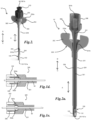
- a device for introducing and/or retaining a medical device through an aperture into a body cavity includes a base, a sleeve and an actuator, as illustrated in FIGs. 1 with device 10 and in FIG. 2 with a variation of the device 10', with base 100, actuator 200 and sleeve 300.
- the device and/or its components may include a distal end toward direction C and a proximal end toward direction D.
- the base 100 may which interfaces and fixes into the aperture, such as a burr hole or twist drill hole through the skull, a sleeve 300 which interfaces with the base 100 and includes a channel 301 through which a medical device is introduced into the base 100, and an actuator 200 which interfaces with the sleeve 300 and/or the base 100 for altering the position and/or other state, such as placement into the aperture, interfacing of the sleeve 300 with the base 100 and/or changing the retention state of the medical device passing through the sleeve 300 and/or base 100.
- the aperture such as a burr hole or twist drill hole through the skull
- a sleeve 300 which interfaces with the base 100 and includes a channel 301 through which a medical device is introduced into the base 100
- an actuator 200 which interfaces with the sleeve 300 and/or the base 100 for altering the position and/or other state, such as placement into the aperture, interfacing of the sleeve 300 with the base 100 and/or changing
- the base 100, sleeve 300 and actuator 200 may generally all include a channel which, when the device is assembled, either form a continuous channel and/or form concentric channels, such as with the channel formed by the base 100 and sleeve 300 being concentric with the channel of the actuator 200, as illustrated in FIGs. 1, 1a, 1b, 1c , 2 and 2a with channels 101, 201 and 301 of the base 100, actuator 200 and sleeve 300, respectively.
- the channels 101, 201 and 301 may further include distal openings 101a, 201a, 301a towards direction C and proximal openings 101b, 201b, 301b towards direction D.
- the base 100 may further be appropriately sized for the size of the aperture being used, such as a burr hole (e.g. generally about 14mm in diameter) or a twist drill hole (e.g. generally about 3mm in diameter).
- a burr hole e.g. generally about 14mm in diameter
- a twist drill hole e.g. generally about 3mm in diameter
- utilization of smaller apertures may be desirable, such as an approximately 3mm twist drill hole, as to reduce the invasiveness and other associated risks with larger openings, and as such the device of the present invention may be desirable for such procedures by utilizing a base 100 that is sized to utilize an approximately 3mm twist drill hole as an entry aperture, with the sleeve 300 and actuator 200 being also appropriately sized to fit the size constraints of a small aperture.
- the base of the device may include a plurality of features and structures for fixing to an aperture into a body cavity, such as a burr hole or twist drill hole into a skull, for holding a medical device in a channel of the base and/or for interfacing with other portions of the device for actuating the holding feature/structure and/or for actuating the base into/out of the aperture.
- a body cavity such as a burr hole or twist drill hole into a skull
- the base includes interfaces for fixing into an aperture into a body cavity such as a burr hole or twist drill hole through a skull, which may generally include screw threads and/or similar interface features such that the base may be secured to the material around the aperture, such as the bone of the skull.
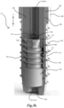
- FIGs. 1, 1a , 2 and 2b illustrate embodiments of a base 100 with interfacing features, shown as threads 102, which may engage and hold onto the material around an aperture, such as bone.
- At least a portion of the base 100 may also include features for aiding insertion and/or fixing into the bone, such as tapering (e.g. for aiding in securely wedging into the aperture), sharp edges (e.g.
- FIGs. 1a and 2b illustrate the tapering toward the distal opening 101a of the channel 101.
- the interface such as the threads 102, may generally be present at a distal portion and/or more of the base 100, such as long substantially the entire base 100.
- the base may further include at least one feature for retaining a medical device in the channel of the base, such as a feature which may be actuated to grasp the medical device in the channel.
- a feature which may be actuated to grasp the medical device in the channel.
- flanges may be included which may press inward in the channel when the base is driven a certain depth into the aperture.
- FIG. 1a illustrates an embodiment of the base 100 with retaining features 104 which extend outward from the surface of the base 100. When the base 100 is inserted into an aperture sufficiently to reach the retaining features 104, they may generally be pushed inward into the channel 101 where they may abut a medical device in the channel 101 to hold it in place.
- a Tuohy-Borst or similar fitting may be utilized in the base 100.
- the base includes at least one retaining member within its channel.
- the at least one retaining member may be, for example, an o-ring or other deformable sealing member.
- the retaining member may generally be ring-shaped and includes a central aperture through which a medical device may be inserted.
- the retaining member may be compressible and/or deformable and may be made from an appropriate material, such as, for example, elastomeric polymers (e.g. silicone, natural or synthetic rubbers, etc.).
- FIGs. 2a and 2b show a retaining member 120 with a channel 120a (which is coextensive with channel 101), where the retaining member 120 is subject to loading from a loading member, shown as inner screw 110.
- the retaining member 120 is generally adapted to deform in response to compressive axial loads such that the aperture (channel 120a) constricts or otherwise decreases in effective size. This may allow the retaining member 120 to securely retain a medical device in the channel 120a by constricting thereon.
- the base 100 may generally include an interface which may be actuated to axially compress (or decompress) the retaining member 120, such as by interfacing with the sleeve 300 such that actuating the sleeve 300 causes axial compression (or decompression) of the retaining member 120.
- the interface may, for example, be present at the proximal end of the base 100, as illustrated with inner screw actuating interface 112 which may interface with corresponding inner screw interface 305' of sleeve 300.
- the interface may include, for example, notches, tabs, splines and/or other similar interface features such that the actuator with corresponding features may interlock with and actuate the base, such as by rotation. As illustrated in FIG.
- the inner screw interface 305' may include splines which nest into notches 112b and may then press on splines 112a when the sleeve 300 is rotated to cause rotation of inner screw 110.
- the rotation may then push the inner screw 110 toward the distal direction C, such as view threading of threads 111 on the inner threads 108 of base 100 to compress retaining member 120.
- the force of the threading interaction may generally hold in place to maintain the level of compression of the retaining member 120 to hold a medical device in place in the channel 120a.
- the base may also include at least one interface for interacting with an actuator such that the base may be secured to (or backed out of) the aperture, such as, for example, by rotating to screw into (or out of) the bone around the aperture.
- an actuation interface 203 on actuator 200 may mate or otherwise interface with actuation interface 103 on base 100.
- the interface may include, for example, notches, tabs, splines and/or other similar interface features such that the actuator with corresponding features may interlock with and actuate the base, such as by rotation.
- the interface may include actuation interface 203 (protrusions) may fit into actuation interface 103 (notches) to lock the actuator 200 and base 100 together such that rotating the actuator 200 may rotate the base 100.
- the interface may generally be present at the proximal end of the base. For example, rotating of the actuator 200 in one direction may generally cause the base 100 to thread into an aperture while rotating the opposite direction may generally cause it back out of the aperture.
- the sleeve of the device may include a plurality of features and structures for holding a medical device in a channel of the sleeve and/or for interfacing with other portions of the device for actuating/fixing the sleeve relative to the base and/or for interfacing with an actuator.
- the sleeve may further include a span section which may create spacing between the proximal and distal ends of the sleeve, such that the proximal end is situated at a distance away from the base/aperture for ease of handling/use, as shown with span section 304 of sleeve 300.
- a sleeve may also be included in the device for interfacing with the base and/or actuator.
- the sleeve may include a channel therethrough which aligns with the channel in the base to form a continuous channel, as illustrated in FIGs. 2a and 2b with channels 101 and 301 of base 100 and sleeve 300, respectively.
- the sleeve 300 may further include features for interfacing with the base, such as threads, friction or close fittings, notches, tabs, splines and/or other attachment features which may interact with corresponding features on the base 100, such as to keep the sleeve in a fixed orientation with the base 100.
- FIG. 1b shows interface 305 which may couple to corresponding features on base 100, such as internal threads (not shown) threading with the interface 305 (shown as threads).
- FIG. 2b illustrates the sleeve 300 being retained in the channel 101 of the base 100 and/or interfacing by the interaction of the inner screw interface 305', which may include splines which nest into notches 112b and splines 112a.
- the sleeve 300 may also include features or structures to couple the sleeve 300 to a retaining feature, such as a Tuohy-Borst fitting or other fitting, such that the sleeve may actuate the retaining feature to hold (or release) a medical device in the channel.
- the interface may generally be present at the distal end of the sleeve.
- the interface may, for example, be present at the distal end of the sleeve 300, as illustrated with inner screw interface 305' of sleeve 300 interfacing with inner screw actuating interface 112 of the inner screw 110 of base 100.
- the interface may include, for example, notches, tabs, splines and/or other similar interface features such that the actuator with corresponding features may interlock with and actuate the base, such as by rotation.
- the inner screw interface 305' may include splines which nest into notches 112b and may then press on splines 112a when the sleeve 300 is rotated to cause rotation of inner screw 110. The rotation may then push the inner screw 110 toward the distal direction C, such as view threading of threads 111 on the inner threads 108 of base 100 to compress retaining member 120.
- the force of the threading interaction may generally hold in place to maintain the level of compression of the retaining member 120 to hold a medical device in place in the channel 120a.
- the sleeve may further include a retention feature for securing a medical device in the channel.
- the retention feature may generally be present at the proximal end of the sleeve, such that, for example, it may be more easily accessed and/or actuated by a user.
- the retention feature may include a fitting, such as a Tuohy-Borst fitting or other fitting, such that the sleeve may be utilized to hold (or release) a medical device in the channel.
- FIGs. 1, 1b , 1d, 1e and 2 illustrate a retaining feature, shown as retaining cap 302, which may be at the end of the sleeve 300 towards distal direction D.
- the retaining cap 302 may be threaded onto or off of threads 306 of sleeve 300 to cause the retaining cap 302 to translate in directions C and D. As shown in FIGs. 1d and 1e , screwing the retaining cap 302 onto the threads 306 may generally cause axial translation of the retaining cap 302 (from FIG. 1d to FIG. 1e ), which may generally compress a retaining member 302a with a channel 302b. A medical device, as shown with medical device 90 in channel 301, may be retained in a position when the channel 302b is constricted due to the compression of retaining member 302a.
- the sleeve 300 may also include features for interfacing with an actuator such that the actuator may be utilized to actuate the sleeve, such as by rotating the sleeve to attach to the base and/or to rotate the sleeve to actuate a portion of the base, such as the retaining feature of base.
- FIGs. 1, 1b, 1c , 2 and 2a illustrate the interfacing of an actuator 200 with the sleeve 300.
- sleeve 300 may include interface features 303 which may interface with actuation features 202a on an actuator 200, such that rotation of the actuator 200 may cause corresponding rotation of the sleeve 300.
- the interface may include, for example, notches, splines, tabs and/or other similar interface features such that the actuator 200 with corresponding features may interlock with and actuate the sleeve 300, such as by rotation.
- actuation features 202a may interface with the interface features 303 (shown as notches).
- the actuator 200 of the device may include a plurality of features and structures for interfacing with other portions of the device for actuating/fixing the sleeve relative to the base and/or for interfacing with the base to secure or back out the base from the aperture.
- the actuator 200 includes a span section 204 which creates spacing between the proximal and distal ends of the sleeve 300, such that the proximal end is situated at a distance away from the base/aperture for ease of handling/use.
- the span section 204 of the actuator 200 is shorter than the span section 304 of the sleeve 300 such that the actuator 200 may slide along the span section 304 of the sleeve 300 within the channel 201 of the actuator 200, as shown with the actuator 200 sliding A between a proximal position, as shown in FIGs.
- actuator 200 interfacing with the sleeve 300, and a distal position, as shown in FIG. 2a with actuator 200 interfacing with the base 100.
- This is desirable to change positions of the actuator 200, such as between interfacing with the sleeve 300 and interfacing with the base 100.
- the actuator 200 may then be utilized for both functions independently.
- the actuator 200 acts as a screwdriver or similar device where features of the actuator 200 interface with corresponding features of the base 100 and/or sleeve 300 such that actuating the actuator 200, such as by rotating it, may cause corresponding actuation of the base 100 and sleeve 300, as appropriate.
- the actuator 200 may, for example, include threads, splines, notches, tabs and/or other features which may mate or otherwise interact with corresponding features on the base 100 and/or sleeve 300.
- an actuation interface 203 on actuator 200 may mate or otherwise interface with actuation interface 103 on base 100.
- the interface may include actuation interface 203 (protrusions) may fit into actuation interface 103 (notches) to lock the actuator 200 and base 100 together such that rotating the actuator 200 may rotate the base 100.
- the interface may generally be present at the proximal end of the actuator 200. For example, rotating of the actuator 200 in one direction may generally cause the base 100 to thread into an aperture while rotating the opposite direction may generally cause it back out of the aperture.
- FIGs. 1, 1b, 1c , 2 and 2a illustrate the interfacing of an actuator 200 with the sleeve 300.
- actuation features 202a on the actuator 200 couple with interface features 303 of the sleeve 300, such that rotation of the actuator 200 causes corresponding rotation of the sleeve 300.
- actuation features 202a may interface with the interface features 303 (shown as notches).
- the actuator 200 may further include handling features which may aid in grasping and/or rotating the actuator, such as handles, flanges, friction areas, splines, and/or any other appropriate handling feature.
- FIGs. 1, 1c , 2 and 2a illustrate handling features 202 on actuator 200, shown as handles which may further, for example, include actuation features 202a to interface with the interface features 303 of the sleeve as discussed above when the actuator 200 is in the proximal position, as shown in FIGs. 1 and 2 .
- the device may further include a driver which may be utilized to control the insertion of a medical device into the channel of the device.
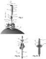
- FIGs. 3, 3a and 3b illustrate the use of a driver 400 with the device 10/10'.
- the driver 400 may include a linear actuator which may grasp and/or otherwise act on the medical device to translate it linearly into/out of the channel.
- a linear actuator which may grasp and/or otherwise act on the medical device to translate it linearly into/out of the channel.
- gears or other structures may be utilized to frictionally or otherwise contact the medical device to drive it in or out of the channel, such as in a highly controlled manner.
- FIGs. 3a and 3b illustrate a linear actuator with translating actuators, such as gears 408, 409, which act on a medical device 90 in a channel 401 of the driver 400 to translate the medical device 90 back and forth in direction B into the channel 101/301 of the device 10/10'.
- the gears 408, 409 may be calibrated such that each given rotation fraction of the gears may translate into a known distance of linear movement of the medical device 90.
- the gears 408, 409 may generally be driven by a motor or other rotational source.
- the driver 400 may, for example, be adapted and/or selected for small linear increments to aid in accurate placement of a medical device at a certain depth.
- the driver may also, for example, register the linear displacement and/or output it to a display for the user to view.
- a microdriver device may include, for example, Microdrive devices (available from FHC, Inc.), which include features for tracking depth of a medical device (e.g. an electrode), such as on the sub-millimeter level and may operate in manual (e.g. by the user actuating the controls) or automatic (e.g. to a set depth) modes.
- the drive 400 may, for example, include controls and display features, such as illustrated in FIG.
- the driver 400 may also include a tare function to zero out the depth at the option of the user.
- the driver 400 may also, for example, include features for outputting display information to a wired or wireless display (e.g. by Bluetooth, WiFi, NFC or other wireless communication).
- the driver 400 may further, for example, be attached to the device 10/10', such as to the sleeve 300, with an interface, such that the driver 400 is coupled to the device 10/10' for fixed positioning of the various components.
- FIGs. 2 and 3 illustrate interface features 310 on the sleeve 300 and interface features 406 on the driver 400, which may include, for example, threads, splines, notches, tabs, Luer locks and/or other features which may mate or otherwise interact with corresponding features.
- the device may be utilized in methods for placing and/or altering the position of medical devices in a body cavity, such as placing/altering the position of electrodes in the brain through a skull aperture, such as a burr hole or twist drill hole.
- the base 100 of the device 10 may be placed into an aperture 82 into a body cavity, such as a burr hole or twist drill hole, through the skull 80 as illustrated in FIG. 3 .
- the base 100 may be placed by driving it into the aperture 82, such as a burr hole or twist drill hole, such as by rotating it with an actuator 200 such that the threads 102 engage the material around the aperture 82 (e.g. bone) to place the base 100 at a desired depth.
- the sleeve 300 may be fixed to the base 100, such as by threading onto the base 100 with threads 305 onto internal threads of the base 100.
- the actuator 200 may further placed onto the sleeve 300 (e.g.
- a medical device 90 such as an electrode, may be passed through the channel 301 in the sleeve 300 into the channel 101 of the base 100 to a desired depth.
- a driver 400 may be utilized to control the advancing/retracting of the medical device 90 in the channel 301.
- the medical device 90 may be retained in a certain position by utilizing the retaining feature of the sleeve 300, such as the retaining cap 302, such as for temporary placement to verify the correct position.
- the medical device 90 may also be retained in a position by actuating the retaining feature of the base 100, such as by driving the base 100 further into the aperture 82 using the actuator 200 in the distal position. This may, for example, be utilized to push the holding features 104 further in such that they press inward into the channel 101 and press against the medical device 90 to hold it in place.
- the medical device 90 may be backed up before a given amount to compensate for the additional depth from the base 100 being driven in further.
- the sleeve 300 and/or actuator 200 may then be removed to leave the secured medical device 90 with the base 100 in the aperture 82. Positioning of the base 100 at a desired position and/or angle may also be facilitated by using a positioning device, such as the stereotactic positioning device 500 as illustrated in FIG. 3 .
- the base 100 of the device 10 may be placed into an aperture 82 into a body cavity, such as a burr hole or twist drill hole, through the skull 80 as illustrated in FIG. 3 .
- the base 100 may be placed by driving it into the aperture 82, such as burr hole or twist drill hole, such as by rotating it with an actuator 200 such that the threads 102 engage the material around the aperture 82 (e.g. bone) to place the base 100 at a desired depth.
- the sleeve 300 may be fixed to the base 100, such as by inserting it into the channel 101 of the base 100 such that the inner screw interface 305' may couple with the inner screw actuation interface 112 of the inner screw 110, as shown in FIG. 2b .
- the actuator 200 may further placed onto the sleeve 300 (e.g. on the span section 304), such that it may be utilized to actuate the base 100, such as to drive it into the aperture 82 while in a distal position, as shown in FIGs. 2a and 3 , and/or to actuate the sleeve 300 to actuate the inner screw 110 while in the proximal position, as shown in FIG. 2 .
- a medical device 90 such as an electrode, may be passed through the channel 301 in the sleeve 300 into the channel 101 of the base 100 to a desired depth.
- a driver 400 may be utilized to control the advancing/retracting of the medical device 90 in the channel 301.
- the medical device 90 may be retained in a certain position by utilizing the retaining feature of the sleeve 300, such as the retaining cap 302, such as for temporary placement to verify the correct position.
- the medical device 90 may also be retained in a position by actuating the retaining feature of the base 100, such as by driving the inner screw 110 to compress the retaining member 120 using the sleeve 300 interacting with the inner screw actuation interface 112.
- the actuator 200 may also be utilized to turn the sleeve 300 by placing it in the proximal position, as shown in FIG. 2 , such that the sleeve interface 202a couples with actuation interface 303. This may, for example, be utilized to constrict the channel 120a to press against the medical device 90 to hold it in place.
- the sleeve 300 and/or actuator 200 may then be removed to leave the secured medical device 90 with the base 100 in the aperture 82. Positioning of the base 100 at a desired position and/or angle may also be facilitated by using a positioning device, such as the stereotactic positioning device 500 as illustrated in FIG. 3 .
- An example of a method, not presently claimed, for placing a medical device, such as an electrode, utilizing the device 10 may generally be utilized, for example, to place an electrode at a desired depth in a human brain, such as to reach a desired structure or region to measure and/or deliver electrical signals.
- the following steps may be employed:
- the actuator 200 may be used in isolation without the sleeve 300 to engage the base 100 and turning to loosen or tighten (with room available for exiting electrode 90 over which the actuator 200 engages the actuation interface 103).
- An example of a method, not presently claimed, for placing a medical device, such as an electrode, utilizing the device 10' may generally be utilized, for example, to place an electrode at a desired depth in a human brain, such as to reach a desired structure or region to measure and/or deliver electrical signals.
- the following steps may be employed:
- the actuator 200 may be used in isolation without the sleeve 300 to engage the base 100 and turning to loosen or tighten (with room available for exiting electrode 90 over which the actuator 200 engages the actuation interface 103).
Landscapes
- Health & Medical Sciences (AREA)
- Life Sciences & Earth Sciences (AREA)
- Surgery (AREA)
- Heart & Thoracic Surgery (AREA)
- General Health & Medical Sciences (AREA)
- Veterinary Medicine (AREA)
- Engineering & Computer Science (AREA)
- Biomedical Technology (AREA)
- Nuclear Medicine, Radiotherapy & Molecular Imaging (AREA)
- Public Health (AREA)
- Animal Behavior & Ethology (AREA)
- Medical Informatics (AREA)
- Molecular Biology (AREA)
- Neurosurgery (AREA)
- Orthopedic Medicine & Surgery (AREA)
- Neurology (AREA)
- Oral & Maxillofacial Surgery (AREA)
- Pathology (AREA)
- Psychology (AREA)
- Cardiology (AREA)
- Radiology & Medical Imaging (AREA)
- Surgical Instruments (AREA)
- Prostheses (AREA)
Claims (13)
- - Ensemble de dispositif d'ancrage osseux pour manipuler un dispositif médical invasif comprenant :une base ayant une forme approximativement cylindrique avec des extrémités proximale et distale, des filets de vissage externes, un premier élément de retenue et un canal de base s'étendant depuis ladite extrémité proximale jusqu'à ladite extrémité distale de ladite base, ledit premier élément de retenue étant adapté pour retenir de manière réversible un dispositif médical dans ledit canal de base ;un manchon ayant des extrémités proximale et distale, un tronçon de recouvrement, une première interface qui se raccorde à ladite base au niveau de ladite extrémité distale dudit manchon, une seconde interface au niveau de ladite extrémité proximale dudit manchon, un second élément de retenue et un canal de manchon s'étendant depuis ladite extrémité proximale jusqu'à ladite extrémité distale dudit manchon et prolongeant ledit canal de base, ledit second élément de retenue étant adapté pour retenir de manière réversible un dispositif médical dans ledit canal de manchon ; etun actionneur ayant des extrémités proximale et distale, un tronçon de recouvrement plus court que ledit tronçon de recouvrement dudit manchon, une première interface adaptée pour se raccorder à ladite base au niveau de ladite extrémité distale dudit actionneur, une seconde interface au niveau de ladite extrémité proximale dudit actionneur adaptée pour se raccorder à ladite seconde interface dudit manchon et un canal d'actionneur s'étendant depuis ladite extrémité proximale jusqu'à ladite extrémité distale dudit actionneur et étant concentrique avec et en dehors dudit tronçon de recouvrement dudit manchon ;dans lequel ledit canal de base et ledit canal de manchon sont adaptés pour recevoir ledit dispositif médical qui les traverse, ledit actionneur pouvant être déplacé par translation le long dudit tronçon de recouvrement dudit manchon entre une première position et une seconde position, ladite première position engageant ladite première interface dudit actionneur avec ladite base pour permettre audit actionneur de pivoter conjointement avec ladite base pour la fixer dans un tissu, et ladite seconde position engageant ladite seconde interface dudit actionneur avec ladite seconde interface dudit manchon pour permettre audit actionneur de pivoter conjointement avec ledit manchon pour engager ledit premier élément de retenue pour retenir de manière réversible ledit dispositif médical.
- - Ensemble de dispositif d'ancrage osseux selon la revendication 1, dans lequel ledit premier élément de retenue comprend un élément de maintien actionné dans ledit canal de base en faisant pivoter ladite première interface dudit actionneur dans ladite seconde position.
- - Ensemble de dispositif d'ancrage osseux selon la revendication 1, dans lequel ledit premier élément de retenue comprend un adaptateur Tuohy-Borst actionné en faisant pivoter ladite première interface dudit manchon pour comprimer un élément de retenue dans ledit adaptateur Tuohy-Borst en faisant pivoter ledit actionneur dans ladite seconde position.
- - Ensemble de dispositif d'ancrage osseux selon la revendication 1, dans lequel ledit second élément de retenue comprend un adaptateur Tuohy-Borst.
- - Ensemble de dispositif d'ancrage osseux selon la revendication 1, comprenant en outre un dispositif d'entraînement adapté pour déplacer en translation ledit dispositif médical dans ledit canal de base.
- - Ensemble de dispositif d'ancrage osseux selon la revendication 1, comprenant en outre un dispositif d'entraînement adapté pour déplacer en translation ledit dispositif médical dans ledit canal de base, ledit dispositif d'entraînement comprenant un microsystème d'entraînement à commande inframillimétrique.
- - Ensemble de dispositif d'ancrage osseux selon la revendication 1, comprenant en outre des éléments de poignée sur ledit actionneur.
- - Ensemble de dispositif d'ancrage osseux selon la revendication 1, dans lequel ladite première interface dudit actionneur et ladite base comprennent des éléments correspondants choisis dans le groupe constitué par des cannelures, des encoches, des creux, des dentures, des languettes, des filets de vissage et des raccords à friction.
- - Ensemble de dispositif d'ancrage osseux selon la revendication 1, dans lequel ladite seconde interface dudit actionneur et ladite seconde interface dudit manchon comprennent des éléments correspondants choisis dans le groupe constitué par des cannelures, des encoches, des creux, des dentures, des languettes, des filets de vissage et des raccords à friction.
- - Ensemble de dispositif d'ancrage osseux selon la revendication 1, dans lequel ladite base et ladite première interface dudit manchon comprennent des éléments correspondants choisis dans le groupe constitué par des cannelures, des encoches, des creux, des dentures, des languettes, des filets de vissage et des raccords à friction.
- - Ensemble de dispositif d'ancrage osseux selon la revendication 1, dans lequel ledit dispositif est fabriqué dans des matériaux compatibles avec l'imagerie par résonance magnétique (IRM) ou avec la radiographie/tomographie informatisée (CT).
- - Ensemble de dispositif d'ancrage osseux selon la revendication 1, dans lequel ledit tronçon de recouvrement dudit manchon traverse ledit canal d'actionneur de sorte que ledit actionneur peut se déplacer par translation entre lesdites première et seconde positions.
- - Ensemble de dispositif d'ancrage osseux selon la revendication 1, comprenant en outre dans ladite base une vis interne adaptée pour comprimer un élément de retenue lorsqu'elle est actionnée par ladite première interface dudit manchon.
Applications Claiming Priority (2)
| Application Number | Priority Date | Filing Date | Title |
|---|---|---|---|
| US201662407472P | 2016-10-12 | 2016-10-12 | |
| PCT/US2017/056387 WO2018071702A1 (fr) | 2016-10-12 | 2017-10-12 | Procédés et dispositifs permettant un placement de dispositif médical |
Publications (4)
| Publication Number | Publication Date |
|---|---|
| EP3525701A1 EP3525701A1 (fr) | 2019-08-21 |
| EP3525701A4 EP3525701A4 (fr) | 2020-06-17 |
| EP3525701C0 EP3525701C0 (fr) | 2024-03-27 |
| EP3525701B1 true EP3525701B1 (fr) | 2024-03-27 |
Family
ID=61906390
Family Applications (1)
| Application Number | Title | Priority Date | Filing Date |
|---|---|---|---|
| EP17859776.1A Active EP3525701B1 (fr) | 2016-10-12 | 2017-10-12 | Dispositifs permettant un placement de dispositif médical |
Country Status (4)
| Country | Link |
|---|---|
| US (2) | US12239493B2 (fr) |
| EP (1) | EP3525701B1 (fr) |
| ES (1) | ES2975257T3 (fr) |
| WO (1) | WO2018071702A1 (fr) |
Families Citing this family (7)
| Publication number | Priority date | Publication date | Assignee | Title |
|---|---|---|---|---|
| PL2558154T3 (pl) | 2010-04-16 | 2020-11-30 | Clearpoint Neuro, Inc. | Systemy chirurgiczne MRI zawierające kaniule chirurgiczne kompatybilne z MRI do transferu substancji do i/lub od pacjenta |
| EP3393571B1 (fr) | 2016-02-17 | 2024-03-06 | ClearPoint Neuro, Inc. | Ensembles de transfert de fluide chirurgicaux intracorporels avec une longueur de canule à pointe d'aiguille exposée réglable, systèmes associés et procédés |
| US11744655B2 (en) * | 2018-12-04 | 2023-09-05 | Globus Medical, Inc. | Drill guide fixtures, cranial insertion fixtures, and related methods and robotic systems |
| US11684750B2 (en) | 2019-10-08 | 2023-06-27 | Clearpoint Neuro, Inc. | Extension tube assembly and related medical fluid transfer systems and methods |
| WO2023083749A1 (fr) * | 2021-11-09 | 2023-05-19 | Icm (Institut Du Cerveau Et De La Moelle Épinière) | Dispositif de vissage, kit et ensemble de positionnement d'ancrage osseux |
| EP4496529A1 (fr) * | 2022-03-22 | 2025-01-29 | ClearPoint Neuro, Inc. | Systèmes de thérapie chirurgicale et procédés associés |
| WO2024092264A1 (fr) * | 2022-10-28 | 2024-05-02 | Accufix Medical Llc. | Appareil d'ancrage médical |
Family Cites Families (11)
| Publication number | Priority date | Publication date | Assignee | Title |
|---|---|---|---|---|
| US4809694A (en) | 1987-05-19 | 1989-03-07 | Ferrara Vincent L | Biopsy guide |
| US5116345A (en) | 1990-11-28 | 1992-05-26 | Ohio Medical Instrument Co., Inc. | Stereotactically implanting an intracranial device |
| US6482182B1 (en) | 1998-09-03 | 2002-11-19 | Surgical Navigation Technologies, Inc. | Anchoring system for a brain lead |
| US6321104B1 (en) | 1998-11-05 | 2001-11-20 | Medtronic, Inc. | Burr hole cap for fixation of cranial lead |
| WO2006099109A2 (fr) | 2005-03-10 | 2006-09-21 | Tyco Healthcare Group Lp | Ancres a sutures |
| US20090192546A1 (en) * | 2005-03-30 | 2009-07-30 | Reinhold Schmieding | Fenestrated suture anchor and method for knotless fixation of tissue |
| EP2355732B1 (fr) | 2008-09-12 | 2015-07-29 | Synthes GmbH | Outil de réduction de tige pour la colonne vertébrale |
| CN102256558A (zh) * | 2008-12-17 | 2011-11-23 | 斯恩蒂斯有限公司 | 用于脊柱矫正手术的杆复位器装置 |
| ES2879450T3 (es) | 2011-05-19 | 2021-11-22 | Synthes Gmbh | Perno craneal articulado |
| WO2014045103A1 (fr) | 2012-09-20 | 2014-03-27 | Mjp Innovations Ag | Implant de hanche |
| US9468751B2 (en) | 2012-12-05 | 2016-10-18 | Medtronic, Inc. | Medical device anchoring apparatus |
-
2017
- 2017-10-12 WO PCT/US2017/056387 patent/WO2018071702A1/fr not_active Ceased
- 2017-10-12 ES ES17859776T patent/ES2975257T3/es active Active
- 2017-10-12 US US16/340,970 patent/US12239493B2/en active Active
- 2017-10-12 EP EP17859776.1A patent/EP3525701B1/fr active Active
-
2025
- 2025-01-18 US US19/031,532 patent/US20250160995A1/en active Pending
Also Published As
| Publication number | Publication date |
|---|---|
| US20250160995A1 (en) | 2025-05-22 |
| EP3525701A1 (fr) | 2019-08-21 |
| US20190282320A1 (en) | 2019-09-19 |
| US12239493B2 (en) | 2025-03-04 |
| WO2018071702A1 (fr) | 2018-04-19 |
| EP3525701A4 (fr) | 2020-06-17 |
| EP3525701C0 (fr) | 2024-03-27 |
| ES2975257T3 (es) | 2024-07-04 |
Similar Documents
| Publication | Publication Date | Title |
|---|---|---|
| EP3525701B1 (fr) | Dispositifs permettant un placement de dispositif médical | |
| US20230233241A1 (en) | Methods and devices for spinal screw insertion | |
| US10974029B2 (en) | Low profile instrument immobilizer | |
| US7918844B2 (en) | Applier for implantable medical device | |
| US7651483B2 (en) | Injection port | |
| US7561916B2 (en) | Implantable medical device with indicator | |
| JP6644514B2 (ja) | 二頭筋腱固定術送達ツール | |
| US7553298B2 (en) | Implantable medical device with cover and method | |
| AU2015201172A1 (en) | Screw insertion instrument | |
| US20220249190A1 (en) | Skull portal device for cranial access | |
| JP5002163B2 (ja) | 特に締め付け要素間の距離を広げる外部固定装置 | |
| US20190083147A1 (en) | Instrument assembly for use with an expandable pedicle screw | |
| WO2022165047A1 (fr) | Dispositifs d'implant osseux modulaire et moyens d'insertion | |
| EP3572007B1 (fr) | Dispositif de suture | |
| US11490887B2 (en) | Suturing apparatus using autotransfer and method thereof | |
| US20250275826A1 (en) | Adjustable depth stop system for surgical accessory | |
| US20240099728A1 (en) | Method and apparatus for surgical drill stop | |
| US20240090967A1 (en) | Method and apparatus for surgical drill stop placement |
Legal Events
| Date | Code | Title | Description |
|---|---|---|---|
| STAA | Information on the status of an ep patent application or granted ep patent |
Free format text: STATUS: THE INTERNATIONAL PUBLICATION HAS BEEN MADE |
|
| PUAI | Public reference made under article 153(3) epc to a published international application that has entered the european phase |
Free format text: ORIGINAL CODE: 0009012 |
|
| STAA | Information on the status of an ep patent application or granted ep patent |
Free format text: STATUS: REQUEST FOR EXAMINATION WAS MADE |
|
| 17P | Request for examination filed |
Effective date: 20190412 |
|
| AK | Designated contracting states |
Kind code of ref document: A1 Designated state(s): AL AT BE BG CH CY CZ DE DK EE ES FI FR GB GR HR HU IE IS IT LI LT LU LV MC MK MT NL NO PL PT RO RS SE SI SK SM TR |
|
| AX | Request for extension of the european patent |
Extension state: BA ME |
|
| DAV | Request for validation of the european patent (deleted) | ||
| DAX | Request for extension of the european patent (deleted) | ||
| A4 | Supplementary search report drawn up and despatched |
Effective date: 20200519 |
|
| RIC1 | Information provided on ipc code assigned before grant |
Ipc: A61B 17/56 20060101ALI20200513BHEP Ipc: A61B 17/88 20060101ALI20200513BHEP Ipc: A61B 17/86 20060101AFI20200513BHEP Ipc: A61N 1/05 20060101ALI20200513BHEP Ipc: A61B 90/10 20160101ALI20200513BHEP Ipc: A61B 90/14 20160101ALI20200513BHEP Ipc: A61B 90/11 20160101ALI20200513BHEP |
|
| RIN1 | Information on inventor provided before grant (corrected) |
Inventor name: KING, RAY Inventor name: GOWDA, ASHOK Inventor name: HOUSSIERE, CHARLES |
|
| GRAP | Despatch of communication of intention to grant a patent |
Free format text: ORIGINAL CODE: EPIDOSNIGR1 |
|
| STAA | Information on the status of an ep patent application or granted ep patent |
Free format text: STATUS: GRANT OF PATENT IS INTENDED |
|
| INTG | Intention to grant announced |
Effective date: 20231121 |
|
| GRAS | Grant fee paid |
Free format text: ORIGINAL CODE: EPIDOSNIGR3 |
|
| GRAA | (expected) grant |
Free format text: ORIGINAL CODE: 0009210 |
|
| STAA | Information on the status of an ep patent application or granted ep patent |
Free format text: STATUS: THE PATENT HAS BEEN GRANTED |
|
| AK | Designated contracting states |
Kind code of ref document: B1 Designated state(s): AL AT BE BG CH CY CZ DE DK EE ES FI FR GB GR HR HU IE IS IT LI LT LU LV MC MK MT NL NO PL PT RO RS SE SI SK SM TR |
|
| REG | Reference to a national code |
Ref country code: GB Ref legal event code: FG4D |
|
| REG | Reference to a national code |
Ref country code: CH Ref legal event code: EP |
|
| REG | Reference to a national code |
Ref country code: DE Ref legal event code: R096 Ref document number: 602017080458 Country of ref document: DE |
|
| REG | Reference to a national code |
Ref country code: IE Ref legal event code: FG4D |
|
| U01 | Request for unitary effect filed |
Effective date: 20240327 |
|
| U07 | Unitary effect registered |
Designated state(s): AT BE BG DE DK EE FI FR IT LT LU LV MT NL PT SE SI Effective date: 20240405 |
|
| REG | Reference to a national code |
Ref country code: ES Ref legal event code: FG2A Ref document number: 2975257 Country of ref document: ES Kind code of ref document: T3 Effective date: 20240704 |
|
| PG25 | Lapsed in a contracting state [announced via postgrant information from national office to epo] |
Ref country code: GR Free format text: LAPSE BECAUSE OF FAILURE TO SUBMIT A TRANSLATION OF THE DESCRIPTION OR TO PAY THE FEE WITHIN THE PRESCRIBED TIME-LIMIT Effective date: 20240628 |
|
| PG25 | Lapsed in a contracting state [announced via postgrant information from national office to epo] |
Ref country code: HR Free format text: LAPSE BECAUSE OF FAILURE TO SUBMIT A TRANSLATION OF THE DESCRIPTION OR TO PAY THE FEE WITHIN THE PRESCRIBED TIME-LIMIT Effective date: 20240327 Ref country code: RS Free format text: LAPSE BECAUSE OF FAILURE TO SUBMIT A TRANSLATION OF THE DESCRIPTION OR TO PAY THE FEE WITHIN THE PRESCRIBED TIME-LIMIT Effective date: 20240627 |
|
| PG25 | Lapsed in a contracting state [announced via postgrant information from national office to epo] |
Ref country code: RS Free format text: LAPSE BECAUSE OF FAILURE TO SUBMIT A TRANSLATION OF THE DESCRIPTION OR TO PAY THE FEE WITHIN THE PRESCRIBED TIME-LIMIT Effective date: 20240627 Ref country code: NO Free format text: LAPSE BECAUSE OF FAILURE TO SUBMIT A TRANSLATION OF THE DESCRIPTION OR TO PAY THE FEE WITHIN THE PRESCRIBED TIME-LIMIT Effective date: 20240627 Ref country code: HR Free format text: LAPSE BECAUSE OF FAILURE TO SUBMIT A TRANSLATION OF THE DESCRIPTION OR TO PAY THE FEE WITHIN THE PRESCRIBED TIME-LIMIT Effective date: 20240327 Ref country code: GR Free format text: LAPSE BECAUSE OF FAILURE TO SUBMIT A TRANSLATION OF THE DESCRIPTION OR TO PAY THE FEE WITHIN THE PRESCRIBED TIME-LIMIT Effective date: 20240628 |
|
| PG25 | Lapsed in a contracting state [announced via postgrant information from national office to epo] |
Ref country code: IS Free format text: LAPSE BECAUSE OF FAILURE TO SUBMIT A TRANSLATION OF THE DESCRIPTION OR TO PAY THE FEE WITHIN THE PRESCRIBED TIME-LIMIT Effective date: 20240727 |
|
| PG25 | Lapsed in a contracting state [announced via postgrant information from national office to epo] |
Ref country code: SM Free format text: LAPSE BECAUSE OF FAILURE TO SUBMIT A TRANSLATION OF THE DESCRIPTION OR TO PAY THE FEE WITHIN THE PRESCRIBED TIME-LIMIT Effective date: 20240327 |
|
| PG25 | Lapsed in a contracting state [announced via postgrant information from national office to epo] |
Ref country code: CZ Free format text: LAPSE BECAUSE OF FAILURE TO SUBMIT A TRANSLATION OF THE DESCRIPTION OR TO PAY THE FEE WITHIN THE PRESCRIBED TIME-LIMIT Effective date: 20240327 |
|
| PG25 | Lapsed in a contracting state [announced via postgrant information from national office to epo] |
Ref country code: PL Free format text: LAPSE BECAUSE OF FAILURE TO SUBMIT A TRANSLATION OF THE DESCRIPTION OR TO PAY THE FEE WITHIN THE PRESCRIBED TIME-LIMIT Effective date: 20240327 |
|
| PG25 | Lapsed in a contracting state [announced via postgrant information from national office to epo] |
Ref country code: SK Free format text: LAPSE BECAUSE OF FAILURE TO SUBMIT A TRANSLATION OF THE DESCRIPTION OR TO PAY THE FEE WITHIN THE PRESCRIBED TIME-LIMIT Effective date: 20240327 |
|
| U20 | Renewal fee for the european patent with unitary effect paid |
Year of fee payment: 8 Effective date: 20240923 |
|
| PG25 | Lapsed in a contracting state [announced via postgrant information from national office to epo] |
Ref country code: SM Free format text: LAPSE BECAUSE OF FAILURE TO SUBMIT A TRANSLATION OF THE DESCRIPTION OR TO PAY THE FEE WITHIN THE PRESCRIBED TIME-LIMIT Effective date: 20240327 Ref country code: SK Free format text: LAPSE BECAUSE OF FAILURE TO SUBMIT A TRANSLATION OF THE DESCRIPTION OR TO PAY THE FEE WITHIN THE PRESCRIBED TIME-LIMIT Effective date: 20240327 Ref country code: RO Free format text: LAPSE BECAUSE OF FAILURE TO SUBMIT A TRANSLATION OF THE DESCRIPTION OR TO PAY THE FEE WITHIN THE PRESCRIBED TIME-LIMIT Effective date: 20240327 Ref country code: PL Free format text: LAPSE BECAUSE OF FAILURE TO SUBMIT A TRANSLATION OF THE DESCRIPTION OR TO PAY THE FEE WITHIN THE PRESCRIBED TIME-LIMIT Effective date: 20240327 Ref country code: IS Free format text: LAPSE BECAUSE OF FAILURE TO SUBMIT A TRANSLATION OF THE DESCRIPTION OR TO PAY THE FEE WITHIN THE PRESCRIBED TIME-LIMIT Effective date: 20240727 Ref country code: CZ Free format text: LAPSE BECAUSE OF FAILURE TO SUBMIT A TRANSLATION OF THE DESCRIPTION OR TO PAY THE FEE WITHIN THE PRESCRIBED TIME-LIMIT Effective date: 20240327 |
|
| REG | Reference to a national code |
Ref country code: DE Ref legal event code: R097 Ref document number: 602017080458 Country of ref document: DE |
|
| PLBE | No opposition filed within time limit |
Free format text: ORIGINAL CODE: 0009261 |
|
| STAA | Information on the status of an ep patent application or granted ep patent |
Free format text: STATUS: NO OPPOSITION FILED WITHIN TIME LIMIT |
|
| 26N | No opposition filed |
Effective date: 20250103 |
|
| REG | Reference to a national code |
Ref country code: CH Ref legal event code: PL |
|
| PG25 | Lapsed in a contracting state [announced via postgrant information from national office to epo] |
Ref country code: MC Free format text: LAPSE BECAUSE OF FAILURE TO SUBMIT A TRANSLATION OF THE DESCRIPTION OR TO PAY THE FEE WITHIN THE PRESCRIBED TIME-LIMIT Effective date: 20240327 |
|
| PG25 | Lapsed in a contracting state [announced via postgrant information from national office to epo] |
Ref country code: CH Free format text: LAPSE BECAUSE OF NON-PAYMENT OF DUE FEES Effective date: 20241031 |
|
| PG25 | Lapsed in a contracting state [announced via postgrant information from national office to epo] |
Ref country code: IE Free format text: LAPSE BECAUSE OF NON-PAYMENT OF DUE FEES Effective date: 20241012 |
|
| U20 | Renewal fee for the european patent with unitary effect paid |
Year of fee payment: 9 Effective date: 20251010 |
|
| REG | Reference to a national code |
Ref country code: ES Ref legal event code: FD2A Effective date: 20251128 |
|
| PGFP | Annual fee paid to national office [announced via postgrant information from national office to epo] |
Ref country code: GB Payment date: 20251013 Year of fee payment: 9 |
|
| PG25 | Lapsed in a contracting state [announced via postgrant information from national office to epo] |
Ref country code: CY Free format text: LAPSE BECAUSE OF FAILURE TO SUBMIT A TRANSLATION OF THE DESCRIPTION OR TO PAY THE FEE WITHIN THE PRESCRIBED TIME-LIMIT; INVALID AB INITIO Effective date: 20171012 |
|
| PG25 | Lapsed in a contracting state [announced via postgrant information from national office to epo] |
Ref country code: ES Free format text: LAPSE BECAUSE OF NON-PAYMENT OF DUE FEES Effective date: 20241013 |
|
| PG25 | Lapsed in a contracting state [announced via postgrant information from national office to epo] |
Ref country code: HU Free format text: LAPSE BECAUSE OF FAILURE TO SUBMIT A TRANSLATION OF THE DESCRIPTION OR TO PAY THE FEE WITHIN THE PRESCRIBED TIME-LIMIT; INVALID AB INITIO Effective date: 20171012 |