EP3527320B1 - Verfahren zur verbindung von wärmeübertragungsplatten eines plattenwärmetauschers - Google Patents
Verfahren zur verbindung von wärmeübertragungsplatten eines plattenwärmetauschers Download PDFInfo
- Publication number
- EP3527320B1 EP3527320B1 EP19160047.7A EP19160047A EP3527320B1 EP 3527320 B1 EP3527320 B1 EP 3527320B1 EP 19160047 A EP19160047 A EP 19160047A EP 3527320 B1 EP3527320 B1 EP 3527320B1
- Authority
- EP
- European Patent Office
- Prior art keywords
- section
- heat transfer
- melting depressant
- depressant composition
- metal sheet
- Prior art date
- Legal status (The legal status is an assumption and is not a legal conclusion. Google has not performed a legal analysis and makes no representation as to the accuracy of the status listed.)
- Active
Links
Images


Classifications
-
- B—PERFORMING OPERATIONS; TRANSPORTING
- B23—MACHINE TOOLS; METAL-WORKING NOT OTHERWISE PROVIDED FOR
- B23K—SOLDERING OR UNSOLDERING; WELDING; CLADDING OR PLATING BY SOLDERING OR WELDING; CUTTING BY APPLYING HEAT LOCALLY, e.g. FLAME CUTTING; WORKING BY LASER BEAM
- B23K35/00—Rods, electrodes, materials, or media, for use in soldering, welding, or cutting
- B23K35/02—Rods, electrodes, materials, or media, for use in soldering, welding, or cutting characterised by mechanical features, e.g. shape
- B23K35/0222—Rods, electrodes, materials, or media, for use in soldering, welding, or cutting characterised by mechanical features, e.g. shape for use in soldering or brazing
-
- B—PERFORMING OPERATIONS; TRANSPORTING
- B23—MACHINE TOOLS; METAL-WORKING NOT OTHERWISE PROVIDED FOR
- B23P—METAL-WORKING NOT OTHERWISE PROVIDED FOR; COMBINED OPERATIONS; UNIVERSAL MACHINE TOOLS
- B23P15/00—Making specific metal objects by operations not covered by a single other subclass or a group in this subclass
-
- B—PERFORMING OPERATIONS; TRANSPORTING
- B21—MECHANICAL METAL-WORKING WITHOUT ESSENTIALLY REMOVING MATERIAL; PUNCHING METAL
- B21D—WORKING OR PROCESSING OF SHEET METAL OR METAL TUBES, RODS OR PROFILES WITHOUT ESSENTIALLY REMOVING MATERIAL; PUNCHING METAL
- B21D53/00—Making other particular articles
- B21D53/02—Making other particular articles heat exchangers or parts thereof, e.g. radiators, condensers fins, headers
- B21D53/04—Making other particular articles heat exchangers or parts thereof, e.g. radiators, condensers fins, headers of sheet metal
-
- B—PERFORMING OPERATIONS; TRANSPORTING
- B23—MACHINE TOOLS; METAL-WORKING NOT OTHERWISE PROVIDED FOR
- B23K—SOLDERING OR UNSOLDERING; WELDING; CLADDING OR PLATING BY SOLDERING OR WELDING; CUTTING BY APPLYING HEAT LOCALLY, e.g. FLAME CUTTING; WORKING BY LASER BEAM
- B23K1/00—Soldering, e.g. brazing, or unsoldering
- B23K1/0008—Soldering, e.g. brazing, or unsoldering specially adapted for particular articles or work
- B23K1/0012—Brazing of heat exchangers
-
- B—PERFORMING OPERATIONS; TRANSPORTING
- B23—MACHINE TOOLS; METAL-WORKING NOT OTHERWISE PROVIDED FOR
- B23K—SOLDERING OR UNSOLDERING; WELDING; CLADDING OR PLATING BY SOLDERING OR WELDING; CUTTING BY APPLYING HEAT LOCALLY, e.g. FLAME CUTTING; WORKING BY LASER BEAM
- B23K3/00—Tools, devices or special appurtenances for soldering, e.g. brazing, or unsoldering, not specially adapted for particular methods
- B23K3/06—Solder feeding devices; Solder melting pans
- B23K3/0607—Solder feeding devices
-
- B—PERFORMING OPERATIONS; TRANSPORTING
- B23—MACHINE TOOLS; METAL-WORKING NOT OTHERWISE PROVIDED FOR
- B23K—SOLDERING OR UNSOLDERING; WELDING; CLADDING OR PLATING BY SOLDERING OR WELDING; CUTTING BY APPLYING HEAT LOCALLY, e.g. FLAME CUTTING; WORKING BY LASER BEAM
- B23K33/00—Specially-profiled edge portions of workpieces for making soldering or welding connections; Filling the seams formed thereby
-
- B—PERFORMING OPERATIONS; TRANSPORTING
- B23—MACHINE TOOLS; METAL-WORKING NOT OTHERWISE PROVIDED FOR
- B23K—SOLDERING OR UNSOLDERING; WELDING; CLADDING OR PLATING BY SOLDERING OR WELDING; CUTTING BY APPLYING HEAT LOCALLY, e.g. FLAME CUTTING; WORKING BY LASER BEAM
- B23K35/00—Rods, electrodes, materials, or media, for use in soldering, welding, or cutting
- B23K35/001—Interlayers, transition pieces for metallurgical bonding of workpieces
- B23K35/002—Interlayers, transition pieces for metallurgical bonding of workpieces at least one of the workpieces being of light metal
-
- B—PERFORMING OPERATIONS; TRANSPORTING
- B23—MACHINE TOOLS; METAL-WORKING NOT OTHERWISE PROVIDED FOR
- B23K—SOLDERING OR UNSOLDERING; WELDING; CLADDING OR PLATING BY SOLDERING OR WELDING; CUTTING BY APPLYING HEAT LOCALLY, e.g. FLAME CUTTING; WORKING BY LASER BEAM
- B23K35/00—Rods, electrodes, materials, or media, for use in soldering, welding, or cutting
- B23K35/22—Rods, electrodes, materials, or media, for use in soldering, welding, or cutting characterised by the composition or nature of the material
- B23K35/24—Selection of soldering or welding materials proper
- B23K35/32—Selection of soldering or welding materials proper with the principal constituent melting at more than 1550°C
- B23K35/325—Ti as the principal constituent
-
- B—PERFORMING OPERATIONS; TRANSPORTING
- B23—MACHINE TOOLS; METAL-WORKING NOT OTHERWISE PROVIDED FOR
- B23P—METAL-WORKING NOT OTHERWISE PROVIDED FOR; COMBINED OPERATIONS; UNIVERSAL MACHINE TOOLS
- B23P15/00—Making specific metal objects by operations not covered by a single other subclass or a group in this subclass
- B23P15/26—Making specific metal objects by operations not covered by a single other subclass or a group in this subclass heat exchangers or the like
-
- F—MECHANICAL ENGINEERING; LIGHTING; HEATING; WEAPONS; BLASTING
- F28—HEAT EXCHANGE IN GENERAL
- F28D—HEAT-EXCHANGE APPARATUS, NOT PROVIDED FOR IN ANOTHER SUBCLASS, IN WHICH THE HEAT-EXCHANGE MEDIA DO NOT COME INTO DIRECT CONTACT
- F28D9/00—Heat-exchange apparatus having stationary plate-like or laminated conduit assemblies for both heat-exchange media, the media being in contact with different sides of a conduit wall
- F28D9/0025—Heat-exchange apparatus having stationary plate-like or laminated conduit assemblies for both heat-exchange media, the media being in contact with different sides of a conduit wall the conduits being formed by zig-zag bend plates
-
- F—MECHANICAL ENGINEERING; LIGHTING; HEATING; WEAPONS; BLASTING
- F28—HEAT EXCHANGE IN GENERAL
- F28D—HEAT-EXCHANGE APPARATUS, NOT PROVIDED FOR IN ANOTHER SUBCLASS, IN WHICH THE HEAT-EXCHANGE MEDIA DO NOT COME INTO DIRECT CONTACT
- F28D9/00—Heat-exchange apparatus having stationary plate-like or laminated conduit assemblies for both heat-exchange media, the media being in contact with different sides of a conduit wall
- F28D9/0031—Heat-exchange apparatus having stationary plate-like or laminated conduit assemblies for both heat-exchange media, the media being in contact with different sides of a conduit wall the conduits for one heat-exchange medium being formed by paired plates touching each other
- F28D9/0043—Heat-exchange apparatus having stationary plate-like or laminated conduit assemblies for both heat-exchange media, the media being in contact with different sides of a conduit wall the conduits for one heat-exchange medium being formed by paired plates touching each other the plates having openings therein for circulation of at least one heat-exchange medium from one conduit to another
- F28D9/005—Heat-exchange apparatus having stationary plate-like or laminated conduit assemblies for both heat-exchange media, the media being in contact with different sides of a conduit wall the conduits for one heat-exchange medium being formed by paired plates touching each other the plates having openings therein for circulation of at least one heat-exchange medium from one conduit to another the plates having openings therein for both heat-exchange media
-
- F—MECHANICAL ENGINEERING; LIGHTING; HEATING; WEAPONS; BLASTING
- F28—HEAT EXCHANGE IN GENERAL
- F28F—DETAILS OF HEAT-EXCHANGE AND HEAT-TRANSFER APPARATUS, OF GENERAL APPLICATION
- F28F21/00—Constructions of heat-exchange apparatus characterised by the selection of particular materials
- F28F21/08—Constructions of heat-exchange apparatus characterised by the selection of particular materials of metal
-
- F—MECHANICAL ENGINEERING; LIGHTING; HEATING; WEAPONS; BLASTING
- F28—HEAT EXCHANGE IN GENERAL
- F28F—DETAILS OF HEAT-EXCHANGE AND HEAT-TRANSFER APPARATUS, OF GENERAL APPLICATION
- F28F3/00—Plate-like or laminated elements; Assemblies of plate-like or laminated elements
- F28F3/02—Elements or assemblies thereof with means for increasing heat-transfer area, e.g. with fins, with recesses, with corrugations
- F28F3/04—Elements or assemblies thereof with means for increasing heat-transfer area, e.g. with fins, with recesses, with corrugations the means being integral with the element
- F28F3/042—Elements or assemblies thereof with means for increasing heat-transfer area, e.g. with fins, with recesses, with corrugations the means being integral with the element in the form of local deformations of the element
- F28F3/046—Elements or assemblies thereof with means for increasing heat-transfer area, e.g. with fins, with recesses, with corrugations the means being integral with the element in the form of local deformations of the element the deformations being linear, e.g. corrugations
-
- F—MECHANICAL ENGINEERING; LIGHTING; HEATING; WEAPONS; BLASTING
- F28—HEAT EXCHANGE IN GENERAL
- F28F—DETAILS OF HEAT-EXCHANGE AND HEAT-TRANSFER APPARATUS, OF GENERAL APPLICATION
- F28F9/00—Casings; Header boxes; Auxiliary supports for elements; Auxiliary members within casings
- F28F9/02—Header boxes; End plates
-
- B—PERFORMING OPERATIONS; TRANSPORTING
- B23—MACHINE TOOLS; METAL-WORKING NOT OTHERWISE PROVIDED FOR
- B23K—SOLDERING OR UNSOLDERING; WELDING; CLADDING OR PLATING BY SOLDERING OR WELDING; CUTTING BY APPLYING HEAT LOCALLY, e.g. FLAME CUTTING; WORKING BY LASER BEAM
- B23K35/00—Rods, electrodes, materials, or media, for use in soldering, welding, or cutting
- B23K35/02—Rods, electrodes, materials, or media, for use in soldering, welding, or cutting characterised by mechanical features, e.g. shape
- B23K35/0222—Rods, electrodes, materials, or media, for use in soldering, welding, or cutting characterised by mechanical features, e.g. shape for use in soldering or brazing
- B23K35/0233—Sheets or foils
-
- B—PERFORMING OPERATIONS; TRANSPORTING
- B23—MACHINE TOOLS; METAL-WORKING NOT OTHERWISE PROVIDED FOR
- B23K—SOLDERING OR UNSOLDERING; WELDING; CLADDING OR PLATING BY SOLDERING OR WELDING; CUTTING BY APPLYING HEAT LOCALLY, e.g. FLAME CUTTING; WORKING BY LASER BEAM
- B23K35/00—Rods, electrodes, materials, or media, for use in soldering, welding, or cutting
- B23K35/02—Rods, electrodes, materials, or media, for use in soldering, welding, or cutting characterised by mechanical features, e.g. shape
- B23K35/0222—Rods, electrodes, materials, or media, for use in soldering, welding, or cutting characterised by mechanical features, e.g. shape for use in soldering or brazing
- B23K35/0244—Powders, particles or spheres; Preforms made therefrom
-
- F—MECHANICAL ENGINEERING; LIGHTING; HEATING; WEAPONS; BLASTING
- F28—HEAT EXCHANGE IN GENERAL
- F28F—DETAILS OF HEAT-EXCHANGE AND HEAT-TRANSFER APPARATUS, OF GENERAL APPLICATION
- F28F2275/00—Fastening; Joining
- F28F2275/04—Fastening; Joining by brazing
- F28F2275/045—Fastening; Joining by brazing with particular processing steps, e.g. by allowing displacement of parts during brazing or by using a reservoir for storing brazing material
Definitions
- the invention relates to a method for joining heat transfer plates of a plate heat exchanger by using a melting depressant composition.
- a plate heat exchanger that is manufactured by the method is also described.
- brazing is done by applying a brazing material on the plates and by heating the plates such that the brazing material melts and forms joints between the plates.
- the brazing material includes a so called filler metal, and it is this metal that forms the joints that joins the plates.
- the brazing material includes a melting depressant composition that causes the filler metal to melt at a temperature that is lower than the melting temperature of the plates that are joined to each other.
- the filler metal and the melting depressant components typically have the form of metal powders.
- the brazing material typically also includes a binder composition that gives the brazing material the form of a paste or a liquid that may be sprayed, painted or in another suitable way applied on the plates. It is important that the brazing material is properly applied on the plates, in the correct amounts and on the correct places.
- EP 2 853 333 A1 discloses a method of joining two metal sheet parts by applying a melting depressant composition on the surface of the first part, the depressant comprising at least 25% (wt) silicon and less than 50% (wt) metallic elements. Afterwards, the second part is brought into contact with the first part and heating is performed until said surface of the first metal sheet melts and forms melted metal at the areas where the melting depressant composition is applied, at the contact points between the sheet and at the end allowing the melted metal layer to solidify and form a joint comprising at least 50 wt% metal which before the heating was part of any of the first metal sheet and the second metal sheet. However, EP 2 853 333 A1 does not disclose that the melting depressant composition is applied in a specific pattern.
- EP 2 837 905 A1 discloses a heat exchanger comprising a number of heat transfer plates with each transfer plate comprising a number of rows with alternating ridges and grooves, but is silent about the use of melting depressant in order to manufacture a plate heat exchanger or heat transfer plate. Moreover EP 2 837 905 A1 , describes welding as a potential method for joining heat transfer plates.
- Applying the melting depressant composition is an operation that involves a risk of introducing errors and faults in the process of joining the heat transfer plates. Thus, it is estimated that there is a need for improving the process of applying the melting depressant composition in self-brazing techniques.
- the method comprises: applying a melting depressant composition comprising combinations of copper, nickel and/or zirconium on a surface of a first metal sheet made of titanium and in a pattern on the first metal sheet, the pattern comprising a number of individual application areas where the melting depressant composition is applied, each application area comprising a mid-section, and a first end section and a second end-section that are located on a respective side of the mid-section; pressing a number of ridges and grooves in the first metal sheet, the ridges extending in a direction that extends from the first end-section to the second end-section of the application areas, such that the application areas are located on top of and along the ridges.
- the metal sheet When the metal sheet has been pressed it is often referred to as a heat transfer plate.
- the pressed first metal sheet (heat transfer plate) is brought into contact with a second, pressed metal sheet (heat transfer plate) made of titanium, such that contact points are formed between the metal sheets where the mid-sections of the application areas are located.
- the first and second metal sheets are then heated until said surface of the first metal sheet melts and forms melted metal at the areas where the melting depressant composition is applied, at the contact points between the sheets.
- the melted metal layer is then allowed to solidify, such that joints are obtained at the contact points.
- the method is advantageous in that individual application areas are applied with the melting depressant composition, since this causes melted metal to be formed only at these areas, which in turn prevents other areas from potentially becoming weaker. As a result the joints between the sheets become stronger.
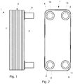
- the plate heat exchanger 1 is made of metal, such as titanium.
- the plate heat exchanger 1 comprises a stack 2 of heat transfer plates, and a first end plate 6 that is arranged on a first side of the stack 2 and a second end plate 7 that is arranged on a second side of the stack 2.
- the end plates 6, 7 have the same shape and form as the heat transfer plates in the stack 2, but are slightly thicker for providing protection against external forces.
- the stack 2 of heat transfer plates are permanently joined to each other to form the plate stack 2 and has alternating first and second flow paths for a first fluid and a second fluid that flow in between the heat transfer plates.
- the plate heat exchanger 1 has a first fluid inlet 10 and a first fluid outlet 11.
- the first fluid inlet 10 receives the first fluid and leads the first fluid to the first flow path between the heat transfer plates in the plate stack 2.
- the first fluid outlet 11 receives the first fluid from the first flow path and allows the fluid to exit the plate heat exchanger 1.
- the plate heat exchanger 1 has a second fluid inlet 12 and a second fluid outlet 13.
- the second fluid inlet 12 receives the second fluid and leads the second fluid to the second flow path between the heat transfer plates.
- the second fluid outlet 13 receives the second fluid from the second flow path and allows the second fluid to exit the plate heat exchanger 1.
- Connectors 8 are arranged around each of the inlets and the outlets, and each connector 8 has the form a pipe. Fluid lines for the two fluids may then be connected to the plate heat exchanger 1 via the connectors 8. Any suitable technique may be used for accomplishing such connection, and the connectors 8 are typically made of the same material as the heat transfer plates in the stack 2. Inlets and outlets for one of the fluids me be reversed, such that there is a co-current flow of the fluids.
- a heat transfer plate 201 that is used for the plate heat exchanger 1 is illustrated.
- the heat transfer plate 201 is also referred to as a metal sheet 201.
- All heat transfer plates in the stack 2 may be identical to the heat transfer plate 201 of Fig. 3 , apart from the end plates 6, 7 which are thicker.
- the heat transfer plates are arranged on top of each other, with every second heat transfer plate turned 180o around a normal direction of a plane that is parallel to the heat transfer plate 201. It is also possible to use two different heat transfer plates, where the different heat transfer plates are stacked alternatively on each other.
- the heat transfer plate 201 has four through holes 210-213, also referred to as port openings, which are aligned with the inlets and outlets 10-13 of the plate heat exchanger 1.
- a pattern 234 in form of alternating tops 236 and grooves 237 is pressed into the heat transfer plate 201.
- the pattern 234 forms a heat transfer area 234 of the heat transfer plate 201.
- the heat transfer plate 201 has a first side 231, or surface 231, and a second side 232, or surface 232, that is opposite the first side 231.
- a peripheral edge 233 extends around the heat transfer plate 201 and is folded from the first side 231 towards the second side 232. The edge 233 abuts an underlying heat transfer plate and provides a seal to the periphery to the underlying heat transfer plate.
- the plate heat exchanger 1 The forms and shapes of the plate heat exchanger 1, the fluid paths for the fluids, the heat transfer plates 201 and the connectors 8 are per se known within the art and can be accomplished according to known techniques. However, the plate heat exchanger 1 is produced in a new manner, by using a melting depressant composition 14 with special properties that effectively joins the heat transfer plates in the stack 2. Before the pattern 234 is pressed and the through holes 210-213 and the edge 233 of the heat transfer plate 201 have been formed, the heat transfer plate 201 has the form of a flat heat transfer plate 201', or first metal sheet 201', as illustrated by Fig. 4 .
- the first heat transfer plate 201' is made of metal and the melting depressant composition 14 comprising combinations of copper, nickel and/or zirconium is applied on the surface 231 of the first heat transfer plate 201' made of titanium before it is pressed and cut.
- Reference numeral 201' indicates the same plate as the plate with reference numeral 201, but before it is pressed and cut.
- the melting depressant composition 14 is applied on the surface 231 of the of a first metal sheet 201', on the first side 231 of the metal sheet 201'.
- the melting depressant composition 14 comprising combinations of copper, nickel and/or zirconium is applied in a pattern 141 on the first metal sheet 201'.
- the pattern 141 comprises a number of individual application areas 142.
- the pattern 141 comprises an edge application group 1411 where the melting depressant composition is applied just inside the peripheral edge 233 of the first metal sheet 201', four port application groups 1412 where the melting depressant composition is applied around the port openings 210-213, and a heat transfer application group 1413 where the melting depressant composition is applied in a so called fish-bone pattern.
- the application groups 1411, 1412, 1413 may be seen in both Fig. 4 and Fig. 3 , but only a part of the heat transfer application group 1413 is illustrated in Fig. 3 .
- Each application group 1411, 1412, 1413 comprises a number of individual application areas, such as the individual application areas 142 of the heat transfer application group 1413.
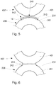
- the individual application areas 142 of the heat transfer application group 1413 are preferably physically separated from each other, and, with further reference to Fig. 7a , the individual application areas 142 comprises a mid-section 145, a first end section 146 and a second end-section 147.
- the first end section 146 and the second end-section 147 are located on a respective side of the mid-section 145.
- Each application area 142 has an elongated shape that extends in a direction D1 from the first end-section 146 to the second end-section 147.
- the application area 142 has a length in the direction D1 that is at least three times greater, or even five times greater, than its width at the mid-section 145.
- the width of the mid-section 145 is measured in a direction that is perpendicular to the direction D1.
- a width of the end-sections 146, 147 may be greater than a width of the mid-section 145.
- Each width of the sections 145, 146, 147 is measured along a direction that is perpendicular to the direction D1.
- the width an individual end-section 146, 147 may be at least 50% wider than the width of the mid-section 145.
- the ridges 236 and grooves 237 of the pressed and cut plate 201 of Fig. 3 extend in the direction D1 that extends from the first end-section 146 to the second end-section 147 of the application areas 142.
- the application areas 142 are arranged in a fish-bone pattern, with the result that there are two directions D1, D1' that extend from first end-sections 146 to second end-sections 147 of the application areas 142.
- These directions D1, D1' are mirror images of each other, as seen relative an axis A that extends though the center of the plate 201, between the port openings 210-213.
- the pressing of the pattern 234 in the plate 201' is done such that the ridges 236 are located where the application areas 142 of the heat transfer application group 1413 are positioned.
- the application areas 142 are then located on top of and along the ridges 236. It can also be said the application areas 142 are located at positions where the ridges 236 will be located after the pattern 234 is pressed in the plate 201'.
- Pressing the pattern 234 and cutting the edges and the port openings 210-213 of the sheet 201' is done according to conventional pressing and cutting techniques that are commonly used for pressing heat transfer plates for plate heat exchangers.
- the application areas 142 are thus applied on a location of the sheet 201' where a ridge shall be located after the pressing and with the ridge direction following the longitudinal extension D1 and D1' of the application areas 142.
- the ridges 236 and grooves 237 form the heat transfer area 234 of the metal sheet 201, and maximum 50%, or maximum 40%, of the heat transfer area 234 is covered by the applied melting depressant composition 14. In one embodiment at least (i.e. a minimum of) 10%, or at least 20%, of the heat transfer area 234 is covered by the applied melting depressant composition 14.
- the melting depressant composition 14 comprises combinations of copper, nickel and/or zirconium, for decreasing a melting temperature of the metal sheet 201', and optionally, a binder component for facilitating the applying of the melting depressant composition 14 on the surface 231.
- the melting depressant composition 14 function is to, when the sheet 201' is heated to a temperature just below its melting point, interact with the metal in the sheet 201' where the melting depressant composition 14 is applied, and cause a surface layer in the metal sheet 201' to melt. The melted metal is then used for forming joints, as will be described in more detail below.
- the melting depressant composition 14 is given a liquid form by using a binder composition and the application may be accomplished by conventional screen printing on a metal surface.
- the melting depressant composition 14 comprises less than 50 wt% metallic elements, or less than 10wt% metallic elements. The calculation of how much wt% metallic elements there is in the melting depressant composition 14 excludes a weight of any binder component that might be used. The calculation is based on elements in the melting depressant composition that from part of the joints, i.e. that remains on the sheet 201' after any binder composition as evaporated.
- melting depressant compositions and metal for the sheet 201' may be found in International patent application No. PCT/EP2016/055296 , where the metal sheet is made of titanium and the melting depressant comprises various combinations of copper, nickel and zirconium.
- the application of the melting depressant compositions may be performed by placing them on the individual application areas and by e.g. rolling the sheet so that the melting depressant compositions becomes attached to the titanium sheet.
- the copper, nickel and/or zirconium may have the form of powder, which the acts a melting depressant component of the melting depressant composition. This melting depressant component may then be mixed with a binder component, so that it may be screen printed on the individual application areas.
- the heat transfer plates in the stack 2 are made of metal sheets like the sheet 201 of Fig. 3 . Every second heat transfer plate is rotated 180° around a normal direction of the plate (e.g. turned 180° clockwise, as seen in Fig. 3 ), and when the plates are stacked on top of each other to form the stack 2, then the ridges 236 of an underlying plate abuts the grooves 437 of the plate above. Every such abutment forms a contact point between the plates. Exactly where the contact points are located depends on the form and shape of the ridges and grooves, and the individual application areas 142 are positioned on the metal sheet where the contact points are located.
- a contact point 240 is formed between the metal sheets 201, 401 where the application area 142 is located.
- Sheet 401 is in the illustrated example identical to the sheet 201, but rotated 180° as described above.
- the mid-section 145 of the application areas 142 is located at the contact point 240.
- Corresponding contact points are formed for all application areas 142 in the heat transfer application group 1413.
- the melting depressant composition 14 causes the surface 231 of the first metal sheet 201 to melt and form a melted metal layer 210 at the area 142 where the melting depressant composition 14 is applied, i.e. at the contact point 240 between the sheets 201, 401.
- the melted metal then flows, by way of capillary action, to the contact point 240 where it is allowed to solidify when the temperature is decreased.
- a joint 241 is then formed obtained at the location of the contact point 240. This happens for all contact points where melting depressant composition 14 is applied.
- the metal of the joint 241 is taken from the sheet 201 where the melting depressant composition 14 was applied, a small depression 242 becomes formed around the joint 241.
- Some metal of the joint 241 may be taken from the other sheet 401, since the melting depressant composition 14 is in contact with this sheet 401 as well. The vast majority of the metal is however taken form the sheet 201 on which the melting depressant composition 14 was applied.
- the joint 241 comprises at least 50 wt%, or at least 70 wt%, or even at least 80 wt% metal that, before the heating that melted the surface 231 of the first metal sheet 201, was part of any of the first metal sheet 201 and the second metal sheet 401.
- the extension of the melting depressant composition 14 along the ridges is advantageous in that it weakens the sheet 201 less than when metal is uniformly taken from around the contact point, i.e. it is from a strength perspective better to draw metal from areas that are in line with the longitudinal direction of the ridge, than from areas that are transverse the direction of the ridge.
- FIG. 7a shows the same shape is in Figs 3 and 4 while Figs 7b - 7e show other shapes of the individual application areas 142b, 142c, 142d and 142e.
- Each of the individual application areas 142, 142b, 142c, 142d and 142e comprises a mid-section 145, a first end section 146 and a second end-section 147, and they all have an elongated shape that extends in the direction D1 from the first end-section 146 to the second end-section 147.
- FIG. 8 a flow chart of a method for joining metal sheets, i.e. heat transfer plates, of the type shown in Fig. 3 is illustrated.
- a first step 401 the melting depressant composition 14 is applied on the surface 231 of the metal sheet 201' of Fig. 4 , in the pattern 141 that has the individual application areas 142 that defines the areas where the melting depressant composition 14 is applied.
- a number of ridges 236 and grooves 237 are pressed in the first metal sheet 201', with the ridges 236 extending in the direction D1 that extends from the first end-section 146 to the second end-section 147 of the application areas 142.
- the application areas 142 are then located on top of and along the ridges 236.
- other application areas also exist, such as around the port openings and along the perimeter of the sheet 201'.
- a next step 403 the pressed heat transfer plate 201 is brought into contact with a second, pressed heat transfer plate 401, which the result that contact points 240 are formed between the heat transfer plates 201, 401 where the mid-sections 145 of the application areas 142 are located, on top of the ridges 236.
- a next step 404 the first and second heat transfer plates 201, 401 are heated until the surface 231 of the first heat transfer plate 201 melts and forms melted metal 210 at the areas 142 where the melting depressant composition 14 is applied.
- a next step 405 the melted metal layer 210 is allowed to solidify by decreasing the temperature, with the result that a joint 241 is obtained at the contact points 240.
- steps of applying 401 melting depressant composition and pressing 402 the sheets is repeatedly performed until a desired number of heat transfer plates are obtained.
- the step of bringing 403 the pressed metal sheets in contact with each other is repeatedly performed until the desired number of heat transfer plates are stacked on top of each other.
- the application 401 of the melting depressant composition, the composition of the melting depressant composition, the heating 404 that causes the metal to melt and the subsequent solidification 405 (cooling) may be performed according to the techniques described in patent document WO2013144211 or in International patent application No. PCT/EP2016/055296 , depending on which metal is used for the heat transfer plates 201, 401 in the plate heat exchanger 1. Suitable metals are exemplified in patent document WO2013144211 and in International patent application No. PCT/EP2016/055296 .
- the steps of pressing 402 the sheet and bringing 403 sheets into contact with each other are performed according to conventional techniques and principles.
- the illustrated embodiment shows application areas 142 and ridges 236 that are arranged in a fish-bone pattern. Other patterns are conceivable, where the application areas 142 still extend along and on top of the ridges.
- the application areas 142 may be used with other, different shapes of application areas, but at least some of the application areas should be formed as above.
- each application area refers to each application area in a set of application areas, which set may be part of a larger set of application areas.
Landscapes
- Engineering & Computer Science (AREA)
- Mechanical Engineering (AREA)
- Physics & Mathematics (AREA)
- Thermal Sciences (AREA)
- General Engineering & Computer Science (AREA)
- Heat-Exchange Devices With Radiators And Conduit Assemblies (AREA)
- Pressure Welding/Diffusion-Bonding (AREA)
Claims (12)
- Verfahren zum Verbinden von Wärmeübertragungsplatten (201, 401) eines Plattenwärmetauschers (1), wobei das Verfahren Folgendes beinhaltet:Applizieren (401) einer Schmelzpunkt-Senkungsmittelzusammensetzung (14), welche Kombinationen aus Kupfer, Nickel und/oder Zirkonium beinhaltet, auf einer Oberfläche (231) eines ersten Metallblechs (201') aus Titan und in einem Muster (141) auf dem ersten Metallblech (201'), wobei das Muster (141) eine Anzahl von einzelnen Applikationsbereichen (142) beinhaltet, wo die Schmelzpunkt-Senkungsmittelzusammensetzung (14) appliziert wird, wobei jeder Applikationsbereich (142) einen Mittelabschnitt (145), einen ersten Endabschnitt (146) und einen zweiten Endabschnitt (147) beinhaltet, welche an einer jeweiligen Seite des Mittelabschnitts (145) befindlich sind,Pressen (402) einer Anzahl von Stegen (236) und Nuten (237) in das erste Metallblech (201'), wobei die Stege (236) sich in eine Richtung (D1) erstrecken, welche sich vom ersten Endabschnitt (146) zum zweiten Endabschnitt (147) der Applikationsbereiche (142) in einer Weise erstrecken, dass die Applikationsbereiche (142) oben auf den und entlang der Stege (236) befindlich sind,Bringen (403) des gepressten ersten Metallblechs (201) in Kontakt mit einem zweiten gepressten Metallblech (401) aus Titan in der Weise, dass Kontaktpunkte (240) zwischen den Metallblechen (201, 401) dort gebildet werden, wo die Mittelabschnitte (145) der Applikationsbereiche (142) befindlich sind,Erhitzen (404) des ersten und des zweiten Metallblechs (201, 401), bis die Oberfläche (231) des ersten Metallblechs (201) schmilzt und geschmolzenes Metall (210) an denjenigen Bereichen (142) bildet, an denen die Schmelzpunkt-Senkungsmittelzusammensetzung (14) appliziert ist, an den Kontaktpunkten (240) zwischen den Blechen (201, 401), unddie geschmolzene Metallschicht (210) in die Lage Versetzen (405), sich in einer Weise zu verfestigen, dass sich Nähte (241) an den Kontaktpunkten (240) bilden.
- Verfahren nach Anspruch 1, wobei jeder Applikationsbereich (142) eine längliche Form besitzt, welche sich in die Richtung (D1) vom ersten Endabschnitt (146) zum zweiten Endabschnitt (147) erstreckt.
- Verfahren nach Anspruch 2, bei welchem jeder Applikationsbereich (142) eine Länge besitzt, welche mindestens drei Mal größer als seine Breite im Mittelabschnitt (145) ist.
- Verfahren nach einem der Ansprüche 1 bis 3, bei welchem eine Breite der Endabschnitte (146, 147) größer ist als eine Breite des Mittelabschnitts (145), wenn sie entlang der Richtung (D1) vom ersten Endabschnitt (146) zum zweiten Endabschnitt (147) betrachtet wird.
- Verfahren nach Anspruch 4, bei welchem eine Breite der Endabschnitte (146, 147) mindestens 50 Prozent breiter ist als eine Breite des Mittelabschnitts (145), wenn sie entlang der Richtung (D1) vom ersten Endabschnitt (146) zum zweiten Endabschnitt (147) betrachtet wird.
- Verfahren nach einem der Ansprüche 1 bis 5, bei welchem die Stege (236) und Nuten (237) einen Wärmeübertragungsbereich (234) des Metallblechs (201) bilden, und bei welchem maximal 50 Prozent des Wärmeübertragungsbereichs (234) mit der applizierten Schmelzpunkt-Senkungsmittelzusammensetzung (14) bedeckt sind.
- Verfahren nach einem der Ansprüche 1 bis 6, bei welchem die Stege (236) und Nuten (237) einen Wärmeübertragungsbereich (234) des Metallblechs (201) bilden, und bei welchem mindestens 20 Prozent des Wärmeübertragungsbereichs (234) mit der applizierten Schmelzpunkt-Senkungsmittelzusammensetzung (14) bedeckt sind.
- Verfahren nach einem der vorhergehenden Ansprüche, wobei der Schritt des Applizierens (401) ferner Rollen des ersten Metallblechs aus Titan beinhaltet, sodass die Schmelzpunkt-Senkungsmittelzusammensetzung sich an dem ersten Metallblech aus Titan befestigt.
- Verfahren nach einem der vorhergehenden Ansprüche, wobei das Kupfer, Nickel und/oder Zirkonium in der Form eines Pulvers vorliegt, welches als eine Schmelzpunkt-Senkungsmittelkomponente der Schmelzpunkt-Senkungsmittelzusammensetzung fungiert.
- Verfahren nach einem der vorhergehenden Ansprüche, wobei die Schmelzpunkt-Senkungsmittelzusammensetzung (14) eine Bindemittelkomponente zum Erleichtern der Applikation (401) der Schmelzpunkt-Senkungsmittelzusammensetzung (14) auf der Oberfläche (231) beinhaltet.
- Verfahren nach Anspruch 9 und 10, wobei der Schritt des Applizierens (401) Siebdrucken der Schmelzpunkt-Senkungsmittelzusammensetzung auf den einzelnen Applikationsbereichen beinhaltet.
- Verfahren nach einem der vorhergehenden Ansprüche, bei welchem die Schmelzpunkt-Senkungsmittelzusammensetzung (14) weniger als 50 Gewichtsprozent metallische Elemente oder weniger als 10 Gewichtsprozent metallische Elemente beinhaltet.
Priority Applications (2)
| Application Number | Priority Date | Filing Date | Title |
|---|---|---|---|
| PL19160047T PL3527320T3 (pl) | 2016-03-31 | 2016-03-31 | Metoda łączenia płyt wymiennika ciepła w płytowym wymienniku ciepła |
| EP19160047.7A EP3527320B1 (de) | 2016-03-31 | 2016-03-31 | Verfahren zur verbindung von wärmeübertragungsplatten eines plattenwärmetauschers |
Applications Claiming Priority (2)
| Application Number | Priority Date | Filing Date | Title |
|---|---|---|---|
| EP16163335.9A EP3225353B1 (de) | 2016-03-31 | 2016-03-31 | Verfahren zum verbinden von wärmeübertragungsplatten eines plattenwärmetauschers |
| EP19160047.7A EP3527320B1 (de) | 2016-03-31 | 2016-03-31 | Verfahren zur verbindung von wärmeübertragungsplatten eines plattenwärmetauschers |
Related Parent Applications (2)
| Application Number | Title | Priority Date | Filing Date |
|---|---|---|---|
| EP16163335.9A Division-Into EP3225353B1 (de) | 2016-03-31 | 2016-03-31 | Verfahren zum verbinden von wärmeübertragungsplatten eines plattenwärmetauschers |
| EP16163335.9A Division EP3225353B1 (de) | 2016-03-31 | 2016-03-31 | Verfahren zum verbinden von wärmeübertragungsplatten eines plattenwärmetauschers |
Publications (2)
| Publication Number | Publication Date |
|---|---|
| EP3527320A1 EP3527320A1 (de) | 2019-08-21 |
| EP3527320B1 true EP3527320B1 (de) | 2020-12-23 |
Family
ID=55699431
Family Applications (2)
| Application Number | Title | Priority Date | Filing Date |
|---|---|---|---|
| EP19160047.7A Active EP3527320B1 (de) | 2016-03-31 | 2016-03-31 | Verfahren zur verbindung von wärmeübertragungsplatten eines plattenwärmetauschers |
| EP16163335.9A Active EP3225353B1 (de) | 2016-03-31 | 2016-03-31 | Verfahren zum verbinden von wärmeübertragungsplatten eines plattenwärmetauschers |
Family Applications After (1)
| Application Number | Title | Priority Date | Filing Date |
|---|---|---|---|
| EP16163335.9A Active EP3225353B1 (de) | 2016-03-31 | 2016-03-31 | Verfahren zum verbinden von wärmeübertragungsplatten eines plattenwärmetauschers |
Country Status (9)
| Country | Link |
|---|---|
| US (2) | US11059092B2 (de) |
| EP (2) | EP3527320B1 (de) |
| JP (1) | JP6685421B2 (de) |
| CN (2) | CN108883506B (de) |
| MY (1) | MY191710A (de) |
| PL (1) | PL3527320T3 (de) |
| SE (1) | SE543805C2 (de) |
| TW (1) | TWI653111B (de) |
| WO (1) | WO2017167597A1 (de) |
Families Citing this family (7)
| Publication number | Priority date | Publication date | Assignee | Title |
|---|---|---|---|---|
| EP3527320B1 (de) | 2016-03-31 | 2020-12-23 | Alfa Laval Corporate AB | Verfahren zur verbindung von wärmeübertragungsplatten eines plattenwärmetauschers |
| SE541917C2 (en) * | 2018-01-16 | 2020-01-07 | Swep Int Ab | Method for producing a brazed plate heat exchanger |
| SE543405C2 (en) * | 2019-05-29 | 2021-01-05 | Alfa Laval Corp Ab | Method for joining metal parts |
| CN110715571B (zh) * | 2019-11-18 | 2023-10-31 | 西安热工研究院有限公司 | 一种印刷电路板熔盐换热器芯体 |
| SE544654C2 (en) * | 2020-07-13 | 2022-10-04 | Swep Int Ab | A method and a system for brazing a plate heat exchanger |
| SE546498C2 (en) * | 2022-06-22 | 2024-11-19 | Alfa Laval Corp Ab | Plate heat exchanger |
| WO2025181225A1 (en) * | 2024-02-29 | 2025-09-04 | Alfa Laval Corporate Ab | Plate stack |
Family Cites Families (22)
| Publication number | Priority date | Publication date | Assignee | Title |
|---|---|---|---|---|
| JPS61176435A (ja) * | 1985-01-31 | 1986-08-08 | Nippon Radiator Co Ltd | 熱交換器用チユ−ブの製造方法 |
| US5287918A (en) | 1990-06-06 | 1994-02-22 | Rolls-Royce Plc | Heat exchangers |
| GB9012618D0 (en) * | 1990-06-06 | 1990-07-25 | Rolls Royce Plc | Heat exchangers |
| JPH09178384A (ja) | 1995-12-22 | 1997-07-11 | Toyo Radiator Co Ltd | プレート型熱交換器のろう付け方法 |
| JP2000337789A (ja) * | 1999-05-24 | 2000-12-08 | Nhk Spring Co Ltd | プレート式熱交換器のろう付け方法 |
| SE519062C2 (sv) | 2001-05-03 | 2003-01-07 | Alfa Laval Corp Ab | Sätt att sammanlöda tunna värmeväxlarplattor samt lödd plattvärmeväxlare framställd enligt sättet |
| SE531472C2 (sv) * | 2005-12-22 | 2009-04-14 | Alfa Laval Corp Ab | Värmeväxlare med värmeöverföringsplatta med jämn lastfördelning på kontaktpunkter vid portområden |
| SE532319C2 (sv) | 2007-07-26 | 2009-12-15 | Titanx Engine Cooling Holding | Värmeväxlare och sätt att tillverka denna |
| BRPI0822416B1 (pt) * | 2008-04-04 | 2020-03-03 | Alfa Laval Corporate Ab | Trocador de calor de placas |
| EP2574420B1 (de) * | 2011-09-29 | 2014-10-22 | Alfa Laval Corporate AB | Lötzusammensetzung auf Eisenbasis und Verfahren zum Verbinden von Wärmeübertragungsplatten |
| WO2013080256A1 (ja) * | 2011-11-30 | 2013-06-06 | 三菱電機株式会社 | プレート式熱交換器およびこの熱交換器を備えた冷凍サイクル装置 |
| DE102012204178B3 (de) * | 2012-03-16 | 2013-03-21 | INSTITUT FüR MIKROTECHNIK MAINZ GMBH | Mikrostrukturbauteil und Verfahren zu dessen Herstellung |
| EP2644312B1 (de) | 2012-03-28 | 2018-10-31 | Alfa Laval Corporate AB | Neuartiges lötkonzept |
| EP2837905B1 (de) * | 2013-08-12 | 2020-02-12 | Alfa Laval Corporate AB | Wärmeübertragungsplatte, wärmetauscher und betriebsverfahren |
| DK2853333T3 (da) * | 2013-09-26 | 2019-11-18 | Alfa Laval Corp Ab | Fremgangsmåde til samling af metaldele ved anvendelse af et smeltepunktsnedsættende lag |
| SI3062949T2 (sl) * | 2013-10-29 | 2023-08-31 | Swep International Ab | Postopek trdega lotanja ploščatega izmenjevalnika toplote s pomočjo s sitotiskom nanešenega lota |
| EP2886997B1 (de) * | 2013-12-18 | 2018-04-18 | Alfa Laval Corporate AB | Wärmetauschplatte und Plattenwärmetauscher |
| CN111238266A (zh) * | 2014-01-29 | 2020-06-05 | 丹佛斯微通道换热器(嘉兴)有限公司 | 热交换板和具有该热交换板的板式热交换器 |
| HUE035381T2 (en) * | 2014-06-18 | 2018-05-02 | Alfa Laval Corp Ab | Thermal transfer plate and plate heat exchanger containing such a heat transfer plate |
| PL3078929T3 (pl) * | 2015-04-07 | 2018-05-30 | Alfa Laval Corporate Ab | Metoda wytwarzania płytowego wymiennika ciepła |
| JP2017110887A (ja) * | 2015-12-18 | 2017-06-22 | 株式会社ノーリツ | プレート式熱交換器、温水装置およびプレート式熱交換器の製造方法 |
| EP3527320B1 (de) | 2016-03-31 | 2020-12-23 | Alfa Laval Corporate AB | Verfahren zur verbindung von wärmeübertragungsplatten eines plattenwärmetauschers |
-
2016
- 2016-03-31 EP EP19160047.7A patent/EP3527320B1/de active Active
- 2016-03-31 PL PL19160047T patent/PL3527320T3/pl unknown
- 2016-03-31 EP EP16163335.9A patent/EP3225353B1/de active Active
-
2017
- 2017-03-20 CN CN201780021321.1A patent/CN108883506B/zh active Active
- 2017-03-20 WO PCT/EP2017/056531 patent/WO2017167597A1/en not_active Ceased
- 2017-03-20 MY MYPI2018703527A patent/MY191710A/en unknown
- 2017-03-20 US US16/080,486 patent/US11059092B2/en active Active
- 2017-03-20 JP JP2018548919A patent/JP6685421B2/ja active Active
- 2017-03-20 SE SE1851229A patent/SE543805C2/en unknown
- 2017-03-20 CN CN202110505870.4A patent/CN113427202B/zh active Active
- 2017-03-22 TW TW106109538A patent/TWI653111B/zh active
-
2021
- 2021-06-11 US US17/345,655 patent/US11396037B2/en active Active
Non-Patent Citations (1)
| Title |
|---|
| None * |
Also Published As
| Publication number | Publication date |
|---|---|
| TW201739552A (zh) | 2017-11-16 |
| EP3225353B1 (de) | 2019-06-12 |
| EP3225353A1 (de) | 2017-10-04 |
| CN108883506A (zh) | 2018-11-23 |
| US11396037B2 (en) | 2022-07-26 |
| US20210299735A1 (en) | 2021-09-30 |
| TWI653111B (zh) | 2019-03-11 |
| PL3527320T3 (pl) | 2021-07-26 |
| WO2017167597A1 (en) | 2017-10-05 |
| US11059092B2 (en) | 2021-07-13 |
| JP2019516052A (ja) | 2019-06-13 |
| CN113427202B (zh) | 2023-09-05 |
| SE543805C2 (en) | 2021-07-27 |
| CN113427202A (zh) | 2021-09-24 |
| EP3527320A1 (de) | 2019-08-21 |
| JP6685421B2 (ja) | 2020-04-22 |
| US20190030654A1 (en) | 2019-01-31 |
| MY191710A (en) | 2022-07-08 |
| SE1851229A1 (en) | 2018-10-09 |
| CN108883506B (zh) | 2021-05-25 |
Similar Documents
| Publication | Publication Date | Title |
|---|---|---|
| US11396037B2 (en) | Method for joining heat transfer plates of a plate heat exchanger | |
| CA2982021C (en) | Method of producing a plate heat exchanger | |
| CN107427920B (zh) | 板式热交换器以及制造板式热交换器的方法 | |
| EP1498682B1 (de) | Titanplatten-wärmetauscher und herstellungsverfahren dafür | |
| KR20030065521A (ko) | 플레이트식 열 교환기 및 그 제조 방법 | |
| DE112017005880B4 (de) | Gestapelter Wärmetauscher | |
| EP3247521B1 (de) | Wärmetauscher mit mikrokanälen und herstellung davon | |
| CN105051481A (zh) | 热交换器的制造方法及热交换器 | |
| TWI640741B (zh) | 鈦板式熱交換器及其生產方法 | |
| EP3507046A1 (de) | Verfahren zur herstellung eines plattenwärmeübertragerblocks mit gezielter applikation des lotmaterials auf insbesondere fins und sidebars | |
| US12397361B2 (en) | Control assembly fabrication via brazing | |
| WO2017140572A1 (de) | Wärmespreizplatte mit mindestens einer kühlfinne, verfahren zur herstellung einer wärmespreizplatte mit mindestens einer kühlfinne, elektronikmodul |
Legal Events
| Date | Code | Title | Description |
|---|---|---|---|
| PUAI | Public reference made under article 153(3) epc to a published international application that has entered the european phase |
Free format text: ORIGINAL CODE: 0009012 |
|
| STAA | Information on the status of an ep patent application or granted ep patent |
Free format text: STATUS: REQUEST FOR EXAMINATION WAS MADE |
|
| 17P | Request for examination filed |
Effective date: 20190228 |
|
| AC | Divisional application: reference to earlier application |
Ref document number: 3225353 Country of ref document: EP Kind code of ref document: P |
|
| AK | Designated contracting states |
Kind code of ref document: A1 Designated state(s): AL AT BE BG CH CY CZ DE DK EE ES FI FR GB GR HR HU IE IS IT LI LT LU LV MC MK MT NL NO PL PT RO RS SE SI SK SM TR |
|
| STAA | Information on the status of an ep patent application or granted ep patent |
Free format text: STATUS: EXAMINATION IS IN PROGRESS |
|
| 17Q | First examination report despatched |
Effective date: 20200401 |
|
| GRAP | Despatch of communication of intention to grant a patent |
Free format text: ORIGINAL CODE: EPIDOSNIGR1 |
|
| STAA | Information on the status of an ep patent application or granted ep patent |
Free format text: STATUS: GRANT OF PATENT IS INTENDED |
|
| INTG | Intention to grant announced |
Effective date: 20201006 |
|
| GRAS | Grant fee paid |
Free format text: ORIGINAL CODE: EPIDOSNIGR3 |
|
| GRAA | (expected) grant |
Free format text: ORIGINAL CODE: 0009210 |
|
| STAA | Information on the status of an ep patent application or granted ep patent |
Free format text: STATUS: THE PATENT HAS BEEN GRANTED |
|
| AC | Divisional application: reference to earlier application |
Ref document number: 3225353 Country of ref document: EP Kind code of ref document: P |
|
| AK | Designated contracting states |
Kind code of ref document: B1 Designated state(s): AL AT BE BG CH CY CZ DE DK EE ES FI FR GB GR HR HU IE IS IT LI LT LU LV MC MK MT NL NO PL PT RO RS SE SI SK SM TR |
|
| REG | Reference to a national code |
Ref country code: GB Ref legal event code: FG4D |
|
| REG | Reference to a national code |
Ref country code: DE Ref legal event code: R096 Ref document number: 602016050454 Country of ref document: DE |
|
| REG | Reference to a national code |
Ref country code: AT Ref legal event code: REF Ref document number: 1347270 Country of ref document: AT Kind code of ref document: T Effective date: 20210115 |
|
| REG | Reference to a national code |
Ref country code: IE Ref legal event code: FG4D |
|
| REG | Reference to a national code |
Ref country code: SE Ref legal event code: TRGR |
|
| PG25 | Lapsed in a contracting state [announced via postgrant information from national office to epo] |
Ref country code: FI Free format text: LAPSE BECAUSE OF FAILURE TO SUBMIT A TRANSLATION OF THE DESCRIPTION OR TO PAY THE FEE WITHIN THE PRESCRIBED TIME-LIMIT Effective date: 20201223 Ref country code: RS Free format text: LAPSE BECAUSE OF FAILURE TO SUBMIT A TRANSLATION OF THE DESCRIPTION OR TO PAY THE FEE WITHIN THE PRESCRIBED TIME-LIMIT Effective date: 20201223 Ref country code: NO Free format text: LAPSE BECAUSE OF FAILURE TO SUBMIT A TRANSLATION OF THE DESCRIPTION OR TO PAY THE FEE WITHIN THE PRESCRIBED TIME-LIMIT Effective date: 20210323 Ref country code: GR Free format text: LAPSE BECAUSE OF FAILURE TO SUBMIT A TRANSLATION OF THE DESCRIPTION OR TO PAY THE FEE WITHIN THE PRESCRIBED TIME-LIMIT Effective date: 20210324 |
|
| REG | Reference to a national code |
Ref country code: AT Ref legal event code: MK05 Ref document number: 1347270 Country of ref document: AT Kind code of ref document: T Effective date: 20201223 |
|
| REG | Reference to a national code |
Ref country code: NL Ref legal event code: MP Effective date: 20201223 |
|
| PG25 | Lapsed in a contracting state [announced via postgrant information from national office to epo] |
Ref country code: LV Free format text: LAPSE BECAUSE OF FAILURE TO SUBMIT A TRANSLATION OF THE DESCRIPTION OR TO PAY THE FEE WITHIN THE PRESCRIBED TIME-LIMIT Effective date: 20201223 Ref country code: BG Free format text: LAPSE BECAUSE OF FAILURE TO SUBMIT A TRANSLATION OF THE DESCRIPTION OR TO PAY THE FEE WITHIN THE PRESCRIBED TIME-LIMIT Effective date: 20210323 |
|
| PG25 | Lapsed in a contracting state [announced via postgrant information from national office to epo] |
Ref country code: NL Free format text: LAPSE BECAUSE OF FAILURE TO SUBMIT A TRANSLATION OF THE DESCRIPTION OR TO PAY THE FEE WITHIN THE PRESCRIBED TIME-LIMIT Effective date: 20201223 Ref country code: HR Free format text: LAPSE BECAUSE OF FAILURE TO SUBMIT A TRANSLATION OF THE DESCRIPTION OR TO PAY THE FEE WITHIN THE PRESCRIBED TIME-LIMIT Effective date: 20201223 |
|
| REG | Reference to a national code |
Ref country code: LT Ref legal event code: MG9D |
|
| PG25 | Lapsed in a contracting state [announced via postgrant information from national office to epo] |
Ref country code: CZ Free format text: LAPSE BECAUSE OF FAILURE TO SUBMIT A TRANSLATION OF THE DESCRIPTION OR TO PAY THE FEE WITHIN THE PRESCRIBED TIME-LIMIT Effective date: 20201223 Ref country code: EE Free format text: LAPSE BECAUSE OF FAILURE TO SUBMIT A TRANSLATION OF THE DESCRIPTION OR TO PAY THE FEE WITHIN THE PRESCRIBED TIME-LIMIT Effective date: 20201223 Ref country code: SM Free format text: LAPSE BECAUSE OF FAILURE TO SUBMIT A TRANSLATION OF THE DESCRIPTION OR TO PAY THE FEE WITHIN THE PRESCRIBED TIME-LIMIT Effective date: 20201223 Ref country code: SK Free format text: LAPSE BECAUSE OF FAILURE TO SUBMIT A TRANSLATION OF THE DESCRIPTION OR TO PAY THE FEE WITHIN THE PRESCRIBED TIME-LIMIT Effective date: 20201223 Ref country code: PT Free format text: LAPSE BECAUSE OF FAILURE TO SUBMIT A TRANSLATION OF THE DESCRIPTION OR TO PAY THE FEE WITHIN THE PRESCRIBED TIME-LIMIT Effective date: 20210423 Ref country code: RO Free format text: LAPSE BECAUSE OF FAILURE TO SUBMIT A TRANSLATION OF THE DESCRIPTION OR TO PAY THE FEE WITHIN THE PRESCRIBED TIME-LIMIT Effective date: 20201223 Ref country code: LT Free format text: LAPSE BECAUSE OF FAILURE TO SUBMIT A TRANSLATION OF THE DESCRIPTION OR TO PAY THE FEE WITHIN THE PRESCRIBED TIME-LIMIT Effective date: 20201223 |
|
| PG25 | Lapsed in a contracting state [announced via postgrant information from national office to epo] |
Ref country code: AT Free format text: LAPSE BECAUSE OF FAILURE TO SUBMIT A TRANSLATION OF THE DESCRIPTION OR TO PAY THE FEE WITHIN THE PRESCRIBED TIME-LIMIT Effective date: 20201223 |
|
| REG | Reference to a national code |
Ref country code: DE Ref legal event code: R097 Ref document number: 602016050454 Country of ref document: DE |
|
| PG25 | Lapsed in a contracting state [announced via postgrant information from national office to epo] |
Ref country code: IS Free format text: LAPSE BECAUSE OF FAILURE TO SUBMIT A TRANSLATION OF THE DESCRIPTION OR TO PAY THE FEE WITHIN THE PRESCRIBED TIME-LIMIT Effective date: 20210423 |
|
| PG25 | Lapsed in a contracting state [announced via postgrant information from national office to epo] |
Ref country code: AL Free format text: LAPSE BECAUSE OF FAILURE TO SUBMIT A TRANSLATION OF THE DESCRIPTION OR TO PAY THE FEE WITHIN THE PRESCRIBED TIME-LIMIT Effective date: 20201223 Ref country code: IT Free format text: LAPSE BECAUSE OF FAILURE TO SUBMIT A TRANSLATION OF THE DESCRIPTION OR TO PAY THE FEE WITHIN THE PRESCRIBED TIME-LIMIT Effective date: 20201223 Ref country code: MC Free format text: LAPSE BECAUSE OF FAILURE TO SUBMIT A TRANSLATION OF THE DESCRIPTION OR TO PAY THE FEE WITHIN THE PRESCRIBED TIME-LIMIT Effective date: 20201223 |
|
| PLBE | No opposition filed within time limit |
Free format text: ORIGINAL CODE: 0009261 |
|
| REG | Reference to a national code |
Ref country code: CH Ref legal event code: PL |
|
| STAA | Information on the status of an ep patent application or granted ep patent |
Free format text: STATUS: NO OPPOSITION FILED WITHIN TIME LIMIT |
|
| GBPC | Gb: european patent ceased through non-payment of renewal fee |
Effective date: 20210331 |
|
| PG25 | Lapsed in a contracting state [announced via postgrant information from national office to epo] |
Ref country code: DK Free format text: LAPSE BECAUSE OF FAILURE TO SUBMIT A TRANSLATION OF THE DESCRIPTION OR TO PAY THE FEE WITHIN THE PRESCRIBED TIME-LIMIT Effective date: 20201223 |
|
| 26N | No opposition filed |
Effective date: 20210924 |
|
| REG | Reference to a national code |
Ref country code: BE Ref legal event code: MM Effective date: 20210331 |
|
| PG25 | Lapsed in a contracting state [announced via postgrant information from national office to epo] |
Ref country code: ES Free format text: LAPSE BECAUSE OF FAILURE TO SUBMIT A TRANSLATION OF THE DESCRIPTION OR TO PAY THE FEE WITHIN THE PRESCRIBED TIME-LIMIT Effective date: 20201223 Ref country code: FR Free format text: LAPSE BECAUSE OF NON-PAYMENT OF DUE FEES Effective date: 20210331 Ref country code: GB Free format text: LAPSE BECAUSE OF NON-PAYMENT OF DUE FEES Effective date: 20210331 Ref country code: CH Free format text: LAPSE BECAUSE OF NON-PAYMENT OF DUE FEES Effective date: 20210331 Ref country code: IE Free format text: LAPSE BECAUSE OF NON-PAYMENT OF DUE FEES Effective date: 20210331 Ref country code: LU Free format text: LAPSE BECAUSE OF NON-PAYMENT OF DUE FEES Effective date: 20210331 Ref country code: LI Free format text: LAPSE BECAUSE OF NON-PAYMENT OF DUE FEES Effective date: 20210331 |
|
| PG25 | Lapsed in a contracting state [announced via postgrant information from national office to epo] |
Ref country code: SI Free format text: LAPSE BECAUSE OF FAILURE TO SUBMIT A TRANSLATION OF THE DESCRIPTION OR TO PAY THE FEE WITHIN THE PRESCRIBED TIME-LIMIT Effective date: 20201223 |
|
| PG25 | Lapsed in a contracting state [announced via postgrant information from national office to epo] |
Ref country code: IS Free format text: LAPSE BECAUSE OF FAILURE TO SUBMIT A TRANSLATION OF THE DESCRIPTION OR TO PAY THE FEE WITHIN THE PRESCRIBED TIME-LIMIT Effective date: 20210423 |
|
| PG25 | Lapsed in a contracting state [announced via postgrant information from national office to epo] |
Ref country code: BE Free format text: LAPSE BECAUSE OF NON-PAYMENT OF DUE FEES Effective date: 20210331 |
|
| P01 | Opt-out of the competence of the unified patent court (upc) registered |
Effective date: 20230420 |
|
| PG25 | Lapsed in a contracting state [announced via postgrant information from national office to epo] |
Ref country code: CY Free format text: LAPSE BECAUSE OF FAILURE TO SUBMIT A TRANSLATION OF THE DESCRIPTION OR TO PAY THE FEE WITHIN THE PRESCRIBED TIME-LIMIT Effective date: 20201223 |
|
| PG25 | Lapsed in a contracting state [announced via postgrant information from national office to epo] |
Ref country code: HU Free format text: LAPSE BECAUSE OF FAILURE TO SUBMIT A TRANSLATION OF THE DESCRIPTION OR TO PAY THE FEE WITHIN THE PRESCRIBED TIME-LIMIT; INVALID AB INITIO Effective date: 20160331 |
|
| PG25 | Lapsed in a contracting state [announced via postgrant information from national office to epo] |
Ref country code: MK Free format text: LAPSE BECAUSE OF FAILURE TO SUBMIT A TRANSLATION OF THE DESCRIPTION OR TO PAY THE FEE WITHIN THE PRESCRIBED TIME-LIMIT Effective date: 20201223 |
|
| PG25 | Lapsed in a contracting state [announced via postgrant information from national office to epo] |
Ref country code: MT Free format text: LAPSE BECAUSE OF FAILURE TO SUBMIT A TRANSLATION OF THE DESCRIPTION OR TO PAY THE FEE WITHIN THE PRESCRIBED TIME-LIMIT Effective date: 20201223 |
|
| PGFP | Annual fee paid to national office [announced via postgrant information from national office to epo] |
Ref country code: PL Payment date: 20250114 Year of fee payment: 10 |
|
| PG25 | Lapsed in a contracting state [announced via postgrant information from national office to epo] |
Ref country code: TR Free format text: LAPSE BECAUSE OF FAILURE TO SUBMIT A TRANSLATION OF THE DESCRIPTION OR TO PAY THE FEE WITHIN THE PRESCRIBED TIME-LIMIT Effective date: 20201223 |
|
| PGFP | Annual fee paid to national office [announced via postgrant information from national office to epo] |
Ref country code: SE Payment date: 20260211 Year of fee payment: 11 |
|
| PGFP | Annual fee paid to national office [announced via postgrant information from national office to epo] |
Ref country code: DE Payment date: 20260102 Year of fee payment: 11 |