EP3527353A2 - Télécommande monolithique - Google Patents
Télécommande monolithique Download PDFInfo
- Publication number
- EP3527353A2 EP3527353A2 EP19164688.4A EP19164688A EP3527353A2 EP 3527353 A2 EP3527353 A2 EP 3527353A2 EP 19164688 A EP19164688 A EP 19164688A EP 3527353 A2 EP3527353 A2 EP 3527353A2
- Authority
- EP
- European Patent Office
- Prior art keywords
- housing
- mold
- plastic housing
- miter
- plastic
- Prior art date
- Legal status (The legal status is an assumption and is not a legal conclusion. Google has not performed a legal analysis and makes no representation as to the accuracy of the status listed.)
- Granted
Links
Images



Classifications
-
- H—ELECTRICITY
- H01—ELECTRIC ELEMENTS
- H01H—ELECTRIC SWITCHES; RELAYS; SELECTORS; EMERGENCY PROTECTIVE DEVICES
- H01H9/00—Details of switching devices, not covered by groups H01H1/00 - H01H7/00
- H01H9/02—Bases, casings, or covers
- H01H9/0214—Hand-held casings
- H01H9/0235—Hand-held casings specially adapted for remote control, e.g. of audio or video apparatus
- H01H9/0242—Protective enclosures; Cushioning means
-
- H—ELECTRICITY
- H01—ELECTRIC ELEMENTS
- H01H—ELECTRIC SWITCHES; RELAYS; SELECTORS; EMERGENCY PROTECTIVE DEVICES
- H01H9/00—Details of switching devices, not covered by groups H01H1/00 - H01H7/00
- H01H9/02—Bases, casings, or covers
- H01H9/0214—Hand-held casings
- H01H9/0235—Hand-held casings specially adapted for remote control, e.g. of audio or video apparatus
-
- B—PERFORMING OPERATIONS; TRANSPORTING
- B29—WORKING OF PLASTICS; WORKING OF SUBSTANCES IN A PLASTIC STATE IN GENERAL
- B29C—SHAPING OR JOINING OF PLASTICS; SHAPING OF MATERIAL IN A PLASTIC STATE, NOT OTHERWISE PROVIDED FOR; AFTER-TREATMENT OF THE SHAPED PRODUCTS, e.g. REPAIRING
- B29C45/00—Injection moulding, i.e. forcing the required volume of moulding material through a nozzle into a closed mould; Apparatus therefor
- B29C45/17—Component parts, details or accessories; Auxiliary operations
- B29C45/40—Removing or ejecting moulded articles
- B29C45/4005—Ejector constructions; Ejector operating mechanisms
- B29C45/401—Ejector pin constructions or mountings
-
- B—PERFORMING OPERATIONS; TRANSPORTING
- B29—WORKING OF PLASTICS; WORKING OF SUBSTANCES IN A PLASTIC STATE IN GENERAL
- B29C—SHAPING OR JOINING OF PLASTICS; SHAPING OF MATERIAL IN A PLASTIC STATE, NOT OTHERWISE PROVIDED FOR; AFTER-TREATMENT OF THE SHAPED PRODUCTS, e.g. REPAIRING
- B29C45/00—Injection moulding, i.e. forcing the required volume of moulding material through a nozzle into a closed mould; Apparatus therefor
- B29C45/17—Component parts, details or accessories; Auxiliary operations
- B29C45/40—Removing or ejecting moulded articles
-
- B—PERFORMING OPERATIONS; TRANSPORTING
- B29—WORKING OF PLASTICS; WORKING OF SUBSTANCES IN A PLASTIC STATE IN GENERAL
- B29C—SHAPING OR JOINING OF PLASTICS; SHAPING OF MATERIAL IN A PLASTIC STATE, NOT OTHERWISE PROVIDED FOR; AFTER-TREATMENT OF THE SHAPED PRODUCTS, e.g. REPAIRING
- B29C66/00—General aspects of processes or apparatus for joining preformed parts
- B29C66/01—General aspects dealing with the joint area or with the area to be joined
- B29C66/05—Particular design of joint configurations
- B29C66/10—Particular design of joint configurations particular design of the joint cross-sections
- B29C66/11—Joint cross-sections comprising a single joint-segment, i.e. one of the parts to be joined comprising a single joint-segment in the joint cross-section
- B29C66/116—Single bevelled joints, i.e. one of the parts to be joined being bevelled in the joint area
- B29C66/1162—Single bevel to bevel joints, e.g. mitre joints
-
- B—PERFORMING OPERATIONS; TRANSPORTING
- B29—WORKING OF PLASTICS; WORKING OF SUBSTANCES IN A PLASTIC STATE IN GENERAL
- B29C—SHAPING OR JOINING OF PLASTICS; SHAPING OF MATERIAL IN A PLASTIC STATE, NOT OTHERWISE PROVIDED FOR; AFTER-TREATMENT OF THE SHAPED PRODUCTS, e.g. REPAIRING
- B29C66/00—General aspects of processes or apparatus for joining preformed parts
- B29C66/50—General aspects of joining tubular articles; General aspects of joining long products, i.e. bars or profiled elements; General aspects of joining single elements to tubular articles, hollow articles or bars; General aspects of joining several hollow-preforms to form hollow or tubular articles
- B29C66/51—Joining tubular articles, profiled elements or bars; Joining single elements to tubular articles, hollow articles or bars; Joining several hollow-preforms to form hollow or tubular articles
- B29C66/54—Joining several hollow-preforms, e.g. half-shells, to form hollow articles, e.g. for making balls, containers; Joining several hollow-preforms, e.g. half-cylinders, to form tubular articles
-
- B—PERFORMING OPERATIONS; TRANSPORTING
- B29—WORKING OF PLASTICS; WORKING OF SUBSTANCES IN A PLASTIC STATE IN GENERAL
- B29C—SHAPING OR JOINING OF PLASTICS; SHAPING OF MATERIAL IN A PLASTIC STATE, NOT OTHERWISE PROVIDED FOR; AFTER-TREATMENT OF THE SHAPED PRODUCTS, e.g. REPAIRING
- B29C66/00—General aspects of processes or apparatus for joining preformed parts
- B29C66/70—General aspects of processes or apparatus for joining preformed parts characterised by the composition, physical properties or the structure of the material of the parts to be joined; Joining with non-plastics material
- B29C66/71—General aspects of processes or apparatus for joining preformed parts characterised by the composition, physical properties or the structure of the material of the parts to be joined; Joining with non-plastics material characterised by the composition of the plastics material of the parts to be joined
-
- B—PERFORMING OPERATIONS; TRANSPORTING
- B29—WORKING OF PLASTICS; WORKING OF SUBSTANCES IN A PLASTIC STATE IN GENERAL
- B29L—INDEXING SCHEME ASSOCIATED WITH SUBCLASS B29C, RELATING TO PARTICULAR ARTICLES
- B29L2031/00—Other particular articles
- B29L2031/34—Electrical apparatus, e.g. sparking plugs or parts thereof
- B29L2031/3481—Housings or casings incorporating or embedding electric or electronic elements
-
- H—ELECTRICITY
- H01—ELECTRIC ELEMENTS
- H01H—ELECTRIC SWITCHES; RELAYS; SELECTORS; EMERGENCY PROTECTIVE DEVICES
- H01H2231/00—Applications
- H01H2231/032—Remote control
-
- H—ELECTRICITY
- H05—ELECTRIC TECHNIQUES NOT OTHERWISE PROVIDED FOR
- H05K—PRINTED CIRCUITS; CASINGS OR CONSTRUCTIONAL DETAILS OF ELECTRIC APPARATUS; MANUFACTURE OF ASSEMBLAGES OF ELECTRICAL COMPONENTS
- H05K5/00—Casings, cabinets or drawers for electric apparatus
- H05K5/10—Casings, cabinets or drawers for electric apparatus comprising several parts forming a closed casing
Definitions
- the present invention relates to a plastic housing for electronic devices, in particular remote controls.
- Such a plastic housing is for example from the DE 10 2010 045 944 A1 known. It comprises a first housing part and a second housing part, wherein the first housing part comprises a directed in the direction of the second housing part joining surface and the second housing part comprises a directed in the direction of the first housing part joining surface and wherein the two housing parts are assembled to the joining surfaces adjacent to each other.
- a plastic housing for electronic devices comprises a first housing part and a second housing part, wherein the first housing part comprises a directed in the direction of the second housing part joining surface and the second housing part comprises a directed in the direction of the first housing part joining surface wherein the two housing parts are assembled to the joining surfaces adjacent to each other, and wherein the joining surfaces are designed as miter surfaces.
- the specified plastic housing is based on the consideration that the aforementioned plastic housing has form-locking elements that the Enlarge joining surface and thus offer the two housing parts a wider attack surface against each other.
- the problem with the interlocking elements is that they must be matched exactly to one another, because otherwise a gap remains between the two housing parts in the assembled state of the plastic housing, which can be perceived as disturbing, especially in areas with high aesthetic requirements.
- the miter surfaces of the housing parts are at least partially formed circumferentially around an interior, which is adapted einhausen an electronic component of the electronic device.
- the miter surfaces are V-shaped and allow it to additionally center the two housing parts against each other.
- the miter surfaces simultaneously fulfill the function of the above-mentioned positive-locking elements.
- the miter surfaces are formed leading into the interior.
- all the blunt edges on the housing parts which are formed by the miter surfaces in the interior of the plastic housing.
- the blunt edges tools such as ejector pins, vent elements or the like can apply in a particularly favorable manner on the interior side in the manufacture of the housing parts, so that any remaining burrs or the like are no longer visible in retrospect.
- the specified plastic housing is produced by a method in which a primary molding material is introduced into the molding spaces forming the housing parts and air from the mold spaces at the ventilation points is discharged, which is located at or adjacent to places in the mold cavities, where the miter surfaces of the housing parts are formed.
- the primary molding material displaces the air present there when it is introduced into the mold space, so that the air must be removed from the mold space.
- the air is removed from the mold space at a parting plane between the tool parts which form the mold space.
- the miter surfaces and thus the molded parts on the outwardly directed side of the remote control are as precisely pointed as possible, the parting planes should be as dense as possible at this point, so that no primary molding material enters the parting plane and thus leaves a burr acting as a disturbing. Due to this dense design of the parting planes, venting of the mold space at the parting plane is practically impossible.
- venting point on or next to the miter surface, preferably in the interior of the plastic housing to be formed, so that the venting on the one hand takes place as close as possible to the miter surface to be formed and so can not be considered annoying burns, inclusions or the like, on the other but also production-related burrs or the like can be arranged in the interior of the plastic housing to be formed.
- leading channels are used for discharging the air from the mold spaces in the mold spaces in which ejector pins are inserted.
- the air duct is kept very small, through which the air is discharged from the mold space, so that after a complete venting of the mold space and correspondingly less primary material penetrates into the vent channel.
- the venting channel is automatically cleaned by the ejector pin when ejecting the urgeformten housing part.
- the primary molding material is introduced at injection points in the mold spaces, which is arranged on one side of the mold space, which is opposite to a side with the venting point.
- the injection points are arranged centrally in the mold spaces, as seen in a molding direction of the primary molding material. In this way it is ensured that the primary material can be distributed evenly in all directions of the mold space. In addition, however, it is also ensured that the primary molding material penetrates into the pointed areas of the mold cavity last and thus does not cure prematurely there, which could clog the mold cavity.
- the mold spaces are formed with mold plates which are hermetically sealed at a separating plane prior to the introduction of the primary mold material into the mold cavities. In this way, the above-mentioned burr at the parting plane in the mold space is avoided.
- the miter surfaces of the housing parts to be formed open into the parting plane.
- the ventilation points are located opposite the miter surfaces of the parting plane. In this way it is ensured that burrs or the like resulting from the venting are arranged in the interior of the plastic housing to be formed and are not visible from the outside.
- a primary molding material is introduced into a mold space forming the housing part, and air is introduced discharged from the mold space at a venting point, which is located at or adjacent to a point in the mold space at which the miter surface of the housing part is formed.
- a channel leading into the forming space is used for discharging the air from the mold space, into which an ejector pin is introduced.
- the primary molding material is introduced at an injection point in the mold space, which is arranged on one side of the mold space, which is opposite to a side with the venting point.
- the injection point is arranged on a central axis of the mold space.
- the mold space is formed by two tool molds which are hermetically sealed at a parting plane prior to introduction of the primary mold material into the mold space.
- the miter surface of the housing part to be formed open into the parting plane.
- the ventilation point is located opposite the miter surface of the parting plane.
- a housing part of one of the specified plastic housing is produced by one of the stated methods.
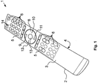
- FIG. 1 shows a remote control 1 for controlling an electronic device, not shown, such as a multimedia device in a perspective view.
- the remote control 1 comprises a plastic housing 2, which is composed of a first housing part in the form of an upper shell 3 and a second housing part lower shell 4, and two keypads 5 with a plurality of key elements 6.
- a plastic housing 2 which is composed of a first housing part in the form of an upper shell 3 and a second housing part lower shell 4, and two keypads 5 with a plurality of key elements 6.
- key elements 6 in the keypad 5 are in the figures of For clarity, not all provided with a reference numeral.
- a control pad 8 is arranged, which comprises a first key element 9, a second key element 10, a third key element 11 and a fourth key element 12.
- the four key elements 9 to 12 are arranged circumferentially and at intervals of 90 ° about a confirmation key 13.
- the control pad 8 with the four key elements 9 to 12 is formed here as a circular disc.
- 1 feedback elements 14 are arranged in the form of small lights on the remote control, which can light up depending on a keystroke on the remote control 1.
- the operation of the exemplary multimedia device is to be controlled.
- a user by means of the buttons 5 on the upper shell 3 of the remote control 1 control commands as information in the remote control 1, which are then transmitted by means of a not shown transmitter to the electronic device to be controlled.
- Such a command can be entered, for example, as a direction command on the key elements 9 to 12, then the movement of a control on the exemplary multimedia device in one of the four possible directions of movement controls.
- the illustration of the remote control 1 is merely exemplary in order to better understand the following technical explanations. However, they can be implemented on any electronic device and in particular on any remote control.
- the plastic housing 2 is produced by prototyping, which will be explained in the following technical embodiments based on the injection molding.
- Fig. 2a to 2c are sections of sectional views of a shell mold duration 15 shown, which provide a mold space 16 for injection molding of the upper shell 3 of the plastic housing 2.
- Fig. 3a to 3c Cutouts of sectional views of a Unterschalendauerform 17 shown that provide a mold cavity 16 for injection molding of the lower shell 4 of the plastic housing 2.
- the upper shell mold 15 comprises a pressure side 18, which is also called the nozzle side 18. Opposite the pressure side 18, the outer shell mold 15 comprises a closing side 19, which is also called the ejector side 19. On the pressure side 18 and closing side 19, the upper shell duration form 15 is enclosed by two clamping plates 20, on which the remaining elements of the upper shell duration form 15 are carried.
- Pressure side 18 is on the platen 20 is an in Fig. 4 shown mold plate 41 is worn, in which a mold insert 21 is inserted.
- a pressure matrix 22 is formed, which forms the convex outer surface of the plastic housing 2 on the upper shell 3.
- Closing side 19 an ejector housing 23 is supported on the platen 20, on the side opposite the platen 20 side with a Pressure plate 24 is closed.
- On the pressure plate 24 is an in Fig. 5 shown closing-side mold plate 41 is worn, in which a closing-side mold insert 21 is inserted.
- the matrix 22 and the core 25 together form the upper shell molding space 16.
- the guide channels 26 have shoulders 28 on which the ejector pins 27 could strike with corresponding counter shoulders 29. From the shoulders 28 and counter shoulders 29 are in the Fig. 2a and 2b not all provided with a reference numeral for clarity. These shoulders 28, 29 are due to the design, because an upper part of the ejector 27 is designed as a flat ejector, while the lower part of the ejector 27 is made for stability and manufacturing reasons around to increase the buckling load capacity.
- the flat ejectors of the ejector pins 27 are guided in the guide channels 26, while the circular areas of the ejector pins 27 are guided below the shoulders 29 in not further referenced Freibohrache.
- the ejector pins 27 are carried on an ejector base plate 30 and positioned in position by an ejector retaining plate 31.
- the two plates 30, 31 are arranged movably in the interior of the ejector housing 23 so that the ejector pins 27 can be moved over them.
- tempering holes 32 through which a temperature control, such as water can be performed to temper the upper shell mold space 16 by cooling or heating.
- a temperature control such as water
- the tempering holes 32 have a minimum distance from the mold space 16 on, which is 10 to 20 times smaller than a width of the upper shell 3 of the plastic housing 2. For the minimum distance 2mm were chosen in the present embodiment.
- the diameter of the Temperierbohronne 32 is between 4 and 5 times as large as the minimum distance. That would be in the present embodiment between 8mm and 10mm. The larger the tempering holes 32 are, the faster the tempering takes place.
- the Unterschalendauerform 17 is constructed in the same manner as the Oberschalendauerform 15. Therefore, in the Fig. 3a to 3c the same reference numerals used as in the Fig. 2a to 2c , The explanations given above with regard to the upper shell duration form 15 apply analogously to the Unterschalendauerform 17. Therefore, a renewed execution for the sake of brevity is omitted.
- a variothermic injection molding process is used for producing an upper shell 3 and / or a lower shell 4. While usually in the injection molding, in particular of plastic under the temperature cooling is understood to dissipate the heat energy of the molten master molding material, the mold cavity 16 is first heated in a variothermal injection molding process prior to injection of the master molding material and then cooled again.
- the mold insert 21 on the Pressure side 18 and on the closing side 19 equal tempered, that is, first warmed up. In this way, in particular during the injection molding of high-gloss housing parts 3, 4, it is ensured that no weld lines occur on the finished product.
- the corresponding mold space 16 is closed.
- the platen 20 is moved on the closing side 19 against the platen 20 on the pressure side 18 until the two mold plates 21, in which the matrix 20 and the core 25 is formed according to touch.
- the heated primary molding material is poured over a in Fig. 5 and 6 to be seen sprue 34 is pressed into the mold space 16.
- a high-gloss plastic housing 2 can be used as the original molding material for the shells 3, 4 methyl methacrylate-acrylonitrile-butadiene-styrene, which is known under the abbreviation M-ABS known.
- This primary molding material should be heated to 114 ° C prior to insertion into the mold cavity 16.
- the primary mold material introduced into the mold space 16 is distributed there and displaces the air present there. This must be removed accordingly, which will be discussed in more detail later.
- the mold inserts 21 are cooled again via the tempering bores 32, so that the primary molding material solidifies.
- cold water is driven through the tempering holes 32.
- the mold space 16 is opened and the molded part produced in this way is ejected from the tool via the ejector pins 27.
- the ejector base plate 30 presses the ejector pins 27 against the open Mold space 16, so that the molded there manufactured molding, so the upper shell 3 or the lower shell 4 dissolves and can fall out of the tool.
- the ejector pins 27 are withdrawn from the Auswerferhalteplatte 31 again, and the entire tool back to the initial state, so that the injection molding process can be restarted.
- the plastic housing 2 of the remote control 1 should be as monolithic as possible. If the upper shell 3 and the lower shell 4 are therefore assembled on a joint surface 36, then a butt joint between the two shells 3, 4 fall on an edge, so that between the two shells 3, 4 as possible no gap is visible. In this way, it would be difficult for the viewer to see whether the plastic housing 2 of the remote control 1 is a one-part or a multi-part component.
- the remote control 1 is replaced in this way a much slimmer appearance, especially when the upper shell 3 is performed in a color contrast to the lower shell 4.
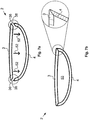
- the joining surfaces 36 on the two shells 3, 4 are designed such that the two shells 3, 4 can be connected to one another via a miter connection. Therefore, the joining surfaces 36 will be referred to below as miter surfaces 36.
- miter surfaces 36 In the production of the miter surfaces 36, however, it should be noted that in this way jumps in the wall thickness 37 occur on the trays 3, 4 to be manufactured, which can lead to errors in the surfaces of the trays 3, 4 to be manufactured.
- the shells 3, 4 at the miter surfaces 36 must taper as far as possible. This requires that the wall thickness 37 drops from a normal wall thickness of, for example, 2 mm to a wall thickness of less than 0.2 mm. Therefore, when using the injection molding method explained above, care must be taken that due to the large cracks in the wall thickness 37, the formation of surface defects such as burns on the shells 3, 4 is not favored.
- a separating plane 38 between the mold inserts can be used for the abovementioned venting of the mold space 16.
- a gap would have to remain in the parting plane, through which the air can escape from the mold space 16 to the outside.
- primary mold material penetrates there, resulting in the formation of burrs.
- burrs contradictieren particular the desired monolithic appearance of the plastic housing 2, which is why a vent on the dividing plane 38 excretes.
- the ejector pins 27 are arranged in the region of the miter surfaces 36 to the inside of the plastic housing 2 to be manufactured in the present embodiment.
- the guide channels 26 and the ejector pins 27 can thus be designed such that a sufficient gap remains between them, over which the mold space 16 can be vented.
- the advantage of this solution is that when ejecting the finished molded part, ie one of the shells 3, 4, the guide channels 26 are simultaneously cleaned by the movement of the ejector pins 27. In addition, the air can escape when ejecting the finished molded part from the guide channels 26 again.
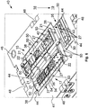
- the mold inserts 21, which each form a mold space 16 must always be placed exactly over one another, in order to ensure an exactly running miter surface 36. This positioning is described below on the basis of 4 to 6 will be explained in more detail, which show in a perspective view corresponding to a pressure-side half 39 and a closing-side half 40 of an injection molding tool in which the Oberschalendauerform 15, the Unterschalendauerform 17 and the Batterieiedeckeldauerform 35 are formed together.
- the mold inserts 21 of the corresponding permanent molds 15, 17 and 35 are held in the mold plates 41.
- the above-mentioned runners 34 are in the Fig. 4 and 5 with the view 33 in FIG Fig. 5 by an arrow in Fig. 4 is indicated.
- the sprue 34 of the upper shell mold 15 opens into a Stauboden 54 on the closing side half 40.
- Stauboden 54 collects to be processed primary material and is deflected so that the primary material emerges from the runner 34 for the to be manufactured upper shell 3 at an angle to its ejection direction , In this way, the runner 34 is performed as a tunnel gate and the upper shell duration form 15 as Abr disposg discernform.
- the halves 39, 40 are provided with a double centering.
- a first centering centered the two halves 39, 40 against each other roughly.
- Tool centering pin 47 screwed which engage in closing the mold space 16 in the corresponding Malawizentrieritn 48 on the closing side half 40.
- Form medicinalzentrierzapfen 49 are further formed on the mold inserts 21 on the pressure-side half, which can be inserted into Form medicinalzentrierabilityn 50 in the mold inserts 21 of the closing side half 40.
- the Form directlyzentierzapfen 49 are made smaller than the horrinum 47, so that when closing the mold cavity 16 first coarse centering acts, and only when it is largely completed, the fine centering is used.
- the sprue channels 34 and thus the injection points on central axes 51 of the mold spaces 16 are arranged so that the primary mold material after penetration into the respective mold space 16 can spread and distribute evenly there , In addition, this ensures that the primary molding material in the edge zones with the above jumps in the wall thickness 37, which form the miter surfaces 36, last penetrates and evenly fills these areas of the mold space 16. Furthermore, it is thus ensured that the primary molding material does not prematurely cure near the sprue channel 34 due to a too thin cavity area.
- the shells 3, 4 produced with the tool and method described above, after ejection from the tool in an in Fig. 6a indicated manner in a joining direction 52 are assembled to the plastic housing 2 and so a in Fig. 6b indicated interior 53 einhausen, in which, for example, a circuit board not shown can be added as electronics of the remote control 1.
- FIG Fig. 8a and 8b An example of an interior view of the manufactured upper shells 3 and lower shells 4 is correspondingly in FIG Fig. 8a and 8b shown. This corresponds to the view of Fig. 8a and 8b that which is formed with the closing half 40 of the tool molds.
- the ejector pins 27 and thus the bearing surfaces 55 are formed rectangular, wherein the broad side of the rectangular shape extends in the circumferential direction about the upper shell 3 or lower shell 4.
- the ejector pins 27 and thus the bearing surfaces 55 are arranged on an edge 53, directed towards the interior 53, of the upper shell 3 or lower shell 4. In this way it is ensured that the outer edges of the two shells 3, 4 close flush and so the monolithic appearance of the remote control is not disturbed.
- the shells 3, 4 can be recessed on the bearing surfaces 55.
- Fig. 8a and 8b are further correspondingly formed by the pin molding elements 42 and sleeve members 43 pin 42 'and sleeves 43' shown, of which for the sake of clarity, not all with a own reference signs are provided. Furthermore, in Fig. 8b to see the point 34 'at which the runner 34 for the lower shell 4 ended. The corresponding point 34 'on the upper shell is in the perspective of Fig. 8a not to be seen.
Landscapes
- Engineering & Computer Science (AREA)
- Mechanical Engineering (AREA)
- Multimedia (AREA)
- Manufacturing & Machinery (AREA)
- Moulds For Moulding Plastics Or The Like (AREA)
- Casings For Electric Apparatus (AREA)
- Selective Calling Equipment (AREA)
- Massaging Devices (AREA)
Applications Claiming Priority (3)
| Application Number | Priority Date | Filing Date | Title |
|---|---|---|---|
| DE102015016784.7A DE102015016784B4 (de) | 2015-12-23 | 2015-12-23 | Monolitische Fernbedienung und Verfahren zur Herstellung derselben |
| EP16815857.4A EP3393753B1 (fr) | 2015-12-23 | 2016-12-20 | Télécommande monolithique |
| PCT/EP2016/082031 WO2017108862A2 (fr) | 2015-12-23 | 2016-12-20 | Télécommande monolithique |
Related Parent Applications (2)
| Application Number | Title | Priority Date | Filing Date |
|---|---|---|---|
| PCT/EP2016/082031 Previously-Filed-Application WO2017108862A2 (fr) | 2015-12-23 | 2016-12-20 | Télécommande monolithique |
| EP16815857.4A Division EP3393753B1 (fr) | 2015-12-23 | 2016-12-20 | Télécommande monolithique |
Publications (4)
| Publication Number | Publication Date |
|---|---|
| EP3527353A2 true EP3527353A2 (fr) | 2019-08-21 |
| EP3527353A3 EP3527353A3 (fr) | 2019-12-04 |
| EP3527353C0 EP3527353C0 (fr) | 2024-11-06 |
| EP3527353B1 EP3527353B1 (fr) | 2024-11-06 |
Family
ID=57589050
Family Applications (2)
| Application Number | Title | Priority Date | Filing Date |
|---|---|---|---|
| EP16815857.4A Active EP3393753B1 (fr) | 2015-12-23 | 2016-12-20 | Télécommande monolithique |
| EP19164688.4A Active EP3527353B1 (fr) | 2015-12-23 | 2016-12-20 | Boitier pour télécommande monolithique |
Family Applications Before (1)
| Application Number | Title | Priority Date | Filing Date |
|---|---|---|---|
| EP16815857.4A Active EP3393753B1 (fr) | 2015-12-23 | 2016-12-20 | Télécommande monolithique |
Country Status (16)
| Country | Link |
|---|---|
| US (2) | US20210166893A1 (fr) |
| EP (2) | EP3393753B1 (fr) |
| JP (1) | JP6951360B2 (fr) |
| CN (1) | CN108602281A (fr) |
| CA (1) | CA3009260C (fr) |
| DE (1) | DE102015016784B4 (fr) |
| DK (1) | DK3393753T3 (fr) |
| ES (1) | ES2737448T3 (fr) |
| HK (1) | HK1256114A1 (fr) |
| HR (1) | HRP20191255T1 (fr) |
| HU (1) | HUE044626T2 (fr) |
| LT (1) | LT3393753T (fr) |
| PL (1) | PL3393753T3 (fr) |
| PT (1) | PT3393753T (fr) |
| SI (1) | SI3393753T1 (fr) |
| WO (1) | WO2017108862A2 (fr) |
Cited By (2)
| Publication number | Priority date | Publication date | Assignee | Title |
|---|---|---|---|---|
| EP3906771A1 (fr) | 2020-05-07 | 2021-11-10 | CLAAS Selbstfahrende Erntemaschinen GmbH | Machine de travail agricole |
| EP3906773A1 (fr) | 2020-05-07 | 2021-11-10 | CLAAS Selbstfahrende Erntemaschinen GmbH | Machine de travail agricole comprenant un engin hybride et un accumulateur d'énergie, l'état de charge de l'accumulateur d'énergie étant controlé sur la base d'un pronostic de la charge de travail attendue |
Families Citing this family (3)
| Publication number | Priority date | Publication date | Assignee | Title |
|---|---|---|---|---|
| CN116648343A (zh) * | 2020-12-28 | 2023-08-25 | 日立安斯泰莫株式会社 | 外壳部件、金属模型装置及电子装置 |
| DE102021127425A1 (de) | 2021-10-21 | 2023-04-27 | Fm Marketing Gmbh | Bruchstabiles elektrisches Handgerät, insbesondere Fernbedienung |
| USD1117156S1 (en) * | 2025-08-27 | 2026-03-10 | Qizhang Yu | Universal remote control |
Citations (1)
| Publication number | Priority date | Publication date | Assignee | Title |
|---|---|---|---|---|
| DE102010045944A1 (de) | 2010-09-21 | 2012-03-22 | Fm Marketing Gmbh | Kunststoffgehäuse für elektronische Geräte, insbesondere für Fernsteuerungen |
Family Cites Families (16)
| Publication number | Priority date | Publication date | Assignee | Title |
|---|---|---|---|---|
| GB1376733A (en) | 1972-10-11 | 1974-12-11 | Scintillant Ltd | Decorative article or plaything |
| JPS62152823A (ja) * | 1985-12-27 | 1987-07-07 | Toyoda Gosei Co Ltd | 減圧成形方法 |
| JPH064622Y2 (ja) * | 1986-06-20 | 1994-02-02 | 三洋電機株式会社 | リモ−トコントロ−ル送信器のケ−ス |
| DE3821433A1 (de) | 1988-06-24 | 1989-12-28 | Altenhofen Hermann Josef | Dreidimensionales puzzle |
| DE19510493A1 (de) * | 1994-03-31 | 1995-10-05 | Marquardt Gmbh | Werkstück aus Kunststoff und Herstellverfahren für ein derartiges Werkstück |
| US5605150A (en) * | 1994-11-04 | 1997-02-25 | Physio-Control Corporation | Electrical interface for a portable electronic physiological instrument having separable components |
| WO2000000337A1 (fr) * | 1998-06-26 | 2000-01-06 | Asahi Glass Company Ltd. | Procede et dispositif de fabrication d'une plaque transparente dotee d'un cadre |
| JP4078499B2 (ja) * | 1998-06-26 | 2008-04-23 | 旭硝子株式会社 | 枠体付き透明板状体の製造方法および枠体付き透明板状体製造用金型 |
| EP1108519B1 (fr) * | 1999-12-13 | 2006-08-16 | Fuji Photo Film Co., Ltd. | Procédé et moule pour la fabrication d'un demi-boiter de cassette. |
| US6877974B2 (en) * | 2000-12-22 | 2005-04-12 | Acushnet Company | Split vent pin for injection molding |
| US7008240B1 (en) * | 2004-04-16 | 2006-03-07 | Super Talent Electronics, Inc. | PC card assembly |
| JP2006326974A (ja) * | 2005-05-25 | 2006-12-07 | Toshiba Corp | 金型装置 |
| US9044898B2 (en) * | 2012-04-03 | 2015-06-02 | Apple Inc. | Methods for joining electronic device housing structures using heat activated thermoset film |
| DE102013207668A1 (de) * | 2013-04-26 | 2014-10-30 | Bayerische Motoren Werke Aktiengesellschaft | Werkzeug zur Herstellung eines Faser-Kunststoff-Verbund-Bauteils mit wenigstens einer Entlüftungsbohrung und darin angeordnetem Auswerferstift |
| DE102013018870A1 (de) * | 2013-11-12 | 2015-05-13 | Kraussmaffei Technologies Gmbh | Vorrichtung zum Herstellen eines Formteils in einem Formwerkzeug einer Maschine zur Herstellung von Kunststoff-Formteilen |
| CN205596480U (zh) * | 2016-04-28 | 2016-09-21 | 嘉兴福气多温控床有限公司 | 遥控器 |
-
2015
- 2015-12-23 DE DE102015016784.7A patent/DE102015016784B4/de not_active Expired - Fee Related
-
2016
- 2016-12-20 HR HRP20191255TT patent/HRP20191255T1/hr unknown
- 2016-12-20 HU HUE16815857 patent/HUE044626T2/hu unknown
- 2016-12-20 PT PT16815857T patent/PT3393753T/pt unknown
- 2016-12-20 EP EP16815857.4A patent/EP3393753B1/fr active Active
- 2016-12-20 HK HK18115191.5A patent/HK1256114A1/zh unknown
- 2016-12-20 LT LTEP16815857.4T patent/LT3393753T/lt unknown
- 2016-12-20 US US16/065,283 patent/US20210166893A1/en not_active Abandoned
- 2016-12-20 DK DK16815857.4T patent/DK3393753T3/da active
- 2016-12-20 EP EP19164688.4A patent/EP3527353B1/fr active Active
- 2016-12-20 CN CN201680068517.1A patent/CN108602281A/zh active Pending
- 2016-12-20 CA CA3009260A patent/CA3009260C/fr active Active
- 2016-12-20 WO PCT/EP2016/082031 patent/WO2017108862A2/fr not_active Ceased
- 2016-12-20 ES ES16815857T patent/ES2737448T3/es active Active
- 2016-12-20 PL PL16815857T patent/PL3393753T3/pl unknown
- 2016-12-20 JP JP2018552125A patent/JP6951360B2/ja not_active Expired - Fee Related
- 2016-12-20 SI SI201630330T patent/SI3393753T1/sl unknown
-
2022
- 2022-08-15 US US17/887,991 patent/US20220392718A1/en not_active Abandoned
Patent Citations (1)
| Publication number | Priority date | Publication date | Assignee | Title |
|---|---|---|---|---|
| DE102010045944A1 (de) | 2010-09-21 | 2012-03-22 | Fm Marketing Gmbh | Kunststoffgehäuse für elektronische Geräte, insbesondere für Fernsteuerungen |
Cited By (5)
| Publication number | Priority date | Publication date | Assignee | Title |
|---|---|---|---|---|
| EP3906771A1 (fr) | 2020-05-07 | 2021-11-10 | CLAAS Selbstfahrende Erntemaschinen GmbH | Machine de travail agricole |
| EP3906773A1 (fr) | 2020-05-07 | 2021-11-10 | CLAAS Selbstfahrende Erntemaschinen GmbH | Machine de travail agricole comprenant un engin hybride et un accumulateur d'énergie, l'état de charge de l'accumulateur d'énergie étant controlé sur la base d'un pronostic de la charge de travail attendue |
| DE102020112451A1 (de) | 2020-05-07 | 2021-11-11 | Claas Selbstfahrende Erntemaschinen Gmbh | Landwirtschaftliche Arbeitsmaschine |
| DE102020112433A1 (de) | 2020-05-07 | 2021-11-11 | Claas Selbstfahrende Erntemaschinen Gmbh | Landwirtschaftliche Arbeitsmaschine |
| US11622504B2 (en) | 2020-05-07 | 2023-04-11 | Claas Selbstfahrende Erntemaschinen Gmbh | Agricultural production machine |
Also Published As
| Publication number | Publication date |
|---|---|
| CA3009260C (fr) | 2023-11-28 |
| EP3527353A3 (fr) | 2019-12-04 |
| US20220392718A1 (en) | 2022-12-08 |
| EP3393753B1 (fr) | 2019-04-24 |
| DE102015016784A1 (de) | 2017-06-29 |
| EP3527353C0 (fr) | 2024-11-06 |
| SI3393753T1 (sl) | 2019-11-29 |
| EP3393753A2 (fr) | 2018-10-31 |
| CN108602281A (zh) | 2018-09-28 |
| WO2017108862A2 (fr) | 2017-06-29 |
| DE102015016784B4 (de) | 2018-12-20 |
| HUE044626T2 (hu) | 2019-11-28 |
| US20210166893A1 (en) | 2021-06-03 |
| JP2019511886A (ja) | 2019-04-25 |
| LT3393753T (lt) | 2019-08-26 |
| PT3393753T (pt) | 2019-08-05 |
| DK3393753T3 (da) | 2019-07-22 |
| EP3527353B1 (fr) | 2024-11-06 |
| JP6951360B2 (ja) | 2021-10-20 |
| WO2017108862A3 (fr) | 2017-08-17 |
| CA3009260A1 (fr) | 2017-06-29 |
| HK1256114A1 (zh) | 2019-09-13 |
| ES2737448T3 (es) | 2020-01-14 |
| HRP20191255T1 (hr) | 2019-10-18 |
| PL3393753T3 (pl) | 2020-03-31 |
Similar Documents
| Publication | Publication Date | Title |
|---|---|---|
| EP3393753B1 (fr) | Télécommande monolithique | |
| DE69601653T2 (de) | Giessvorrichtung | |
| DE69514615T2 (de) | Giessverfahren und Vorrichtung | |
| EP3790732A1 (fr) | Procédé de fabrication d'une semelle de chaussure, en particulier de chaussure de sport | |
| EP1813404B1 (fr) | Outil de formage | |
| DE10000580A1 (de) | Herstellung eines Schreibgeräte-Vorderteils mit einstückigem Verformling | |
| DE10231551A1 (de) | Formwerkzeug für Kunststoff-Gehäuseteile | |
| EP3222399B1 (fr) | Dispositif et procede de fabrication d'un objet moule presentant au moins une percee | |
| DE102009031604A1 (de) | Sandgusswerkzeug | |
| WO2019120804A1 (fr) | Procédé de production d'une partie de moule ainsi qu'insert d'alimentation destiné à être utilisé dans un tel procédé | |
| EP2134528B1 (fr) | Moule avec cadre, à structure modulaire | |
| DE102011116258A1 (de) | Verfahren zu Herstellung eines mehrkomponentigen Spritzgießteils | |
| DE102007001756B4 (de) | Verfahren und Spritzgussform zum Spritzgießen von hohlen Formteilen aus Kunststoff | |
| DE102010018114B4 (de) | Verfahren zur Herstellung von Bauteilen mittels Polymer- oder Kunststoffguss oder aus Faserverbund-Kunststoffen | |
| DE102020105878A1 (de) | Kombiniertes spritzgiessen und extrudieren | |
| EP4378657A1 (fr) | Outil de moulage par injection et procédé de fabrication de pièces moulées par injection | |
| DE102012102008A1 (de) | Vorrichtung und Verfahren zum Herstellen von Kunststoffteilen | |
| DE840905C (de) | Spritzgiessform | |
| EP1741531A1 (fr) | Moule pour la fabrication d'un écran thérmique en céramique | |
| DE202012100844U1 (de) | Vorrichtung zum Herstellen von Kunststoffteilen | |
| DE4235776C2 (de) | Formwerkzeug zum Herstellen von Kunststoffteilen sowie Verfahren zum Herstellen eines solchen Formwerkzeugs | |
| DE102004056451A1 (de) | Werkzeug und Verfahren zur Herstellung von Formkörpern mit Öffnungen | |
| EP4311649A1 (fr) | Élément d'isolation ainsi que système et procédé de fabrication d'un tel élément d'isolation | |
| DE102016100970A1 (de) | Verfahren zum Herstellen eines Kunststoffbauteils und Kunststoffbauteil | |
| EP4552821A1 (fr) | Outil pour mouler par injection des pièces en matière plastique et procédé pour son fonctionnement |
Legal Events
| Date | Code | Title | Description |
|---|---|---|---|
| PUAI | Public reference made under article 153(3) epc to a published international application that has entered the european phase |
Free format text: ORIGINAL CODE: 0009012 |
|
| STAA | Information on the status of an ep patent application or granted ep patent |
Free format text: STATUS: THE APPLICATION HAS BEEN PUBLISHED |
|
| AC | Divisional application: reference to earlier application |
Ref document number: 3393753 Country of ref document: EP Kind code of ref document: P |
|
| AK | Designated contracting states |
Kind code of ref document: A2 Designated state(s): AL AT BE BG CH CY CZ DE DK EE ES FI FR GB GR HR HU IE IS IT LI LT LU LV MC MK MT NL NO PL PT RO RS SE SI SK SM TR |
|
| PUAL | Search report despatched |
Free format text: ORIGINAL CODE: 0009013 |
|
| AK | Designated contracting states |
Kind code of ref document: A3 Designated state(s): AL AT BE BG CH CY CZ DE DK EE ES FI FR GB GR HR HU IE IS IT LI LT LU LV MC MK MT NL NO PL PT RO RS SE SI SK SM TR |
|
| RIC1 | Information provided on ipc code assigned before grant |
Ipc: H01H 9/02 20060101ALI20191029BHEP Ipc: B29C 45/40 20060101ALN20191029BHEP Ipc: B29C 65/00 20060101AFI20191029BHEP |
|
| STAA | Information on the status of an ep patent application or granted ep patent |
Free format text: STATUS: REQUEST FOR EXAMINATION WAS MADE |
|
| 17P | Request for examination filed |
Effective date: 20200604 |
|
| RBV | Designated contracting states (corrected) |
Designated state(s): AL AT BE BG CH CY CZ DE DK EE ES FI FR GB GR HR HU IE IS IT LI LT LU LV MC MK MT NL NO PL PT RO RS SE SI SK SM TR |
|
| STAA | Information on the status of an ep patent application or granted ep patent |
Free format text: STATUS: EXAMINATION IS IN PROGRESS |
|
| 17Q | First examination report despatched |
Effective date: 20211221 |
|
| GRAP | Despatch of communication of intention to grant a patent |
Free format text: ORIGINAL CODE: EPIDOSNIGR1 |
|
| STAA | Information on the status of an ep patent application or granted ep patent |
Free format text: STATUS: GRANT OF PATENT IS INTENDED |
|
| INTG | Intention to grant announced |
Effective date: 20240528 |
|
| GRAS | Grant fee paid |
Free format text: ORIGINAL CODE: EPIDOSNIGR3 |
|
| GRAA | (expected) grant |
Free format text: ORIGINAL CODE: 0009210 |
|
| STAA | Information on the status of an ep patent application or granted ep patent |
Free format text: STATUS: THE PATENT HAS BEEN GRANTED |
|
| AC | Divisional application: reference to earlier application |
Ref document number: 3393753 Country of ref document: EP Kind code of ref document: P |
|
| AK | Designated contracting states |
Kind code of ref document: B1 Designated state(s): AL AT BE BG CH CY CZ DE DK EE ES FI FR GB GR HR HU IE IS IT LI LT LU LV MC MK MT NL NO PL PT RO RS SE SI SK SM TR |
|
| REG | Reference to a national code |
Ref country code: GB Ref legal event code: FG4D Free format text: NOT ENGLISH |
|
| REG | Reference to a national code |
Ref country code: CH Ref legal event code: EP |
|
| REG | Reference to a national code |
Ref country code: DE Ref legal event code: R096 Ref document number: 502016016789 Country of ref document: DE |
|
| REG | Reference to a national code |
Ref country code: IE Ref legal event code: FG4D Free format text: LANGUAGE OF EP DOCUMENT: GERMAN |
|
| U01 | Request for unitary effect filed |
Effective date: 20241205 |
|
| U07 | Unitary effect registered |
Designated state(s): AT BE BG DE DK EE FI FR IT LT LU LV MT NL PT RO SE SI Effective date: 20250115 |
|
| U20 | Renewal fee for the european patent with unitary effect paid |
Year of fee payment: 9 Effective date: 20250123 |
|
| PG25 | Lapsed in a contracting state [announced via postgrant information from national office to epo] |
Ref country code: HR Free format text: LAPSE BECAUSE OF FAILURE TO SUBMIT A TRANSLATION OF THE DESCRIPTION OR TO PAY THE FEE WITHIN THE PRESCRIBED TIME-LIMIT Effective date: 20241106 Ref country code: IS Free format text: LAPSE BECAUSE OF FAILURE TO SUBMIT A TRANSLATION OF THE DESCRIPTION OR TO PAY THE FEE WITHIN THE PRESCRIBED TIME-LIMIT Effective date: 20250306 |
|
| PG25 | Lapsed in a contracting state [announced via postgrant information from national office to epo] |
Ref country code: ES Free format text: LAPSE BECAUSE OF FAILURE TO SUBMIT A TRANSLATION OF THE DESCRIPTION OR TO PAY THE FEE WITHIN THE PRESCRIBED TIME-LIMIT Effective date: 20241106 |
|
| PG25 | Lapsed in a contracting state [announced via postgrant information from national office to epo] |
Ref country code: NO Free format text: LAPSE BECAUSE OF FAILURE TO SUBMIT A TRANSLATION OF THE DESCRIPTION OR TO PAY THE FEE WITHIN THE PRESCRIBED TIME-LIMIT Effective date: 20250206 |
|
| PG25 | Lapsed in a contracting state [announced via postgrant information from national office to epo] |
Ref country code: GR Free format text: LAPSE BECAUSE OF FAILURE TO SUBMIT A TRANSLATION OF THE DESCRIPTION OR TO PAY THE FEE WITHIN THE PRESCRIBED TIME-LIMIT Effective date: 20250207 |
|
| PG25 | Lapsed in a contracting state [announced via postgrant information from national office to epo] |
Ref country code: PL Free format text: LAPSE BECAUSE OF FAILURE TO SUBMIT A TRANSLATION OF THE DESCRIPTION OR TO PAY THE FEE WITHIN THE PRESCRIBED TIME-LIMIT Effective date: 20241106 |
|
| PG25 | Lapsed in a contracting state [announced via postgrant information from national office to epo] |
Ref country code: RS Free format text: LAPSE BECAUSE OF FAILURE TO SUBMIT A TRANSLATION OF THE DESCRIPTION OR TO PAY THE FEE WITHIN THE PRESCRIBED TIME-LIMIT Effective date: 20250206 |
|
| PG25 | Lapsed in a contracting state [announced via postgrant information from national office to epo] |
Ref country code: SM Free format text: LAPSE BECAUSE OF FAILURE TO SUBMIT A TRANSLATION OF THE DESCRIPTION OR TO PAY THE FEE WITHIN THE PRESCRIBED TIME-LIMIT Effective date: 20241106 |
|
| PG25 | Lapsed in a contracting state [announced via postgrant information from national office to epo] |
Ref country code: SK Free format text: LAPSE BECAUSE OF FAILURE TO SUBMIT A TRANSLATION OF THE DESCRIPTION OR TO PAY THE FEE WITHIN THE PRESCRIBED TIME-LIMIT Effective date: 20241106 |
|
| PG25 | Lapsed in a contracting state [announced via postgrant information from national office to epo] |
Ref country code: CZ Free format text: LAPSE BECAUSE OF FAILURE TO SUBMIT A TRANSLATION OF THE DESCRIPTION OR TO PAY THE FEE WITHIN THE PRESCRIBED TIME-LIMIT Effective date: 20241106 |
|
| REG | Reference to a national code |
Ref country code: CH Ref legal event code: PL |
|
| PLBE | No opposition filed within time limit |
Free format text: ORIGINAL CODE: 0009261 |
|
| STAA | Information on the status of an ep patent application or granted ep patent |
Free format text: STATUS: NO OPPOSITION FILED WITHIN TIME LIMIT |
|
| PG25 | Lapsed in a contracting state [announced via postgrant information from national office to epo] |
Ref country code: MC Free format text: LAPSE BECAUSE OF FAILURE TO SUBMIT A TRANSLATION OF THE DESCRIPTION OR TO PAY THE FEE WITHIN THE PRESCRIBED TIME-LIMIT Effective date: 20241106 |
|
| 26N | No opposition filed |
Effective date: 20250807 |
|
| PG25 | Lapsed in a contracting state [announced via postgrant information from national office to epo] |
Ref country code: CH Free format text: LAPSE BECAUSE OF NON-PAYMENT OF DUE FEES Effective date: 20241231 |
|
| PG25 | Lapsed in a contracting state [announced via postgrant information from national office to epo] |
Ref country code: IE Free format text: LAPSE BECAUSE OF NON-PAYMENT OF DUE FEES Effective date: 20241220 |
|
| GBPC | Gb: european patent ceased through non-payment of renewal fee |
Effective date: 20250206 |
|
| U20 | Renewal fee for the european patent with unitary effect paid |
Year of fee payment: 10 Effective date: 20251121 |
|
| PG25 | Lapsed in a contracting state [announced via postgrant information from national office to epo] |
Ref country code: GB Free format text: LAPSE BECAUSE OF NON-PAYMENT OF DUE FEES Effective date: 20250206 |
|
| PG25 | Lapsed in a contracting state [announced via postgrant information from national office to epo] |
Ref country code: CY Free format text: LAPSE BECAUSE OF FAILURE TO SUBMIT A TRANSLATION OF THE DESCRIPTION OR TO PAY THE FEE WITHIN THE PRESCRIBED TIME-LIMIT Effective date: 20241106 |
|
| PG25 | Lapsed in a contracting state [announced via postgrant information from national office to epo] |
Ref country code: TR Free format text: LAPSE BECAUSE OF FAILURE TO SUBMIT A TRANSLATION OF THE DESCRIPTION OR TO PAY THE FEE WITHIN THE PRESCRIBED TIME-LIMIT Effective date: 20241106 |
|
| PG25 | Lapsed in a contracting state [announced via postgrant information from national office to epo] |
Ref country code: HU Free format text: LAPSE BECAUSE OF FAILURE TO SUBMIT A TRANSLATION OF THE DESCRIPTION OR TO PAY THE FEE WITHIN THE PRESCRIBED TIME-LIMIT; INVALID AB INITIO Effective date: 20161220 |