EP1813404B1 - Outil de formage - Google Patents
Outil de formage Download PDFInfo
- Publication number
- EP1813404B1 EP1813404B1 EP07001643.1A EP07001643A EP1813404B1 EP 1813404 B1 EP1813404 B1 EP 1813404B1 EP 07001643 A EP07001643 A EP 07001643A EP 1813404 B1 EP1813404 B1 EP 1813404B1
- Authority
- EP
- European Patent Office
- Prior art keywords
- casting
- moulding tool
- tool according
- die
- shell
- Prior art date
- Legal status (The legal status is an assumption and is not a legal conclusion. Google has not performed a legal analysis and makes no representation as to the accuracy of the status listed.)
- Not-in-force
Links
- 238000000465 moulding Methods 0.000 title claims description 19
- 238000005266 casting Methods 0.000 claims description 31
- 238000000034 method Methods 0.000 claims description 13
- 238000003801 milling Methods 0.000 claims description 7
- 239000002131 composite material Substances 0.000 claims description 5
- 239000000463 material Substances 0.000 claims description 5
- 238000005498 polishing Methods 0.000 claims description 5
- 229910001315 Tool steel Inorganic materials 0.000 claims description 4
- 239000004033 plastic Substances 0.000 claims description 2
- 229920003023 plastic Polymers 0.000 claims description 2
- 229910010293 ceramic material Inorganic materials 0.000 claims 1
- 238000010276 construction Methods 0.000 claims 1
- PXHVJJICTQNCMI-UHFFFAOYSA-N Nickel Chemical compound [Ni] PXHVJJICTQNCMI-UHFFFAOYSA-N 0.000 description 10
- 238000004519 manufacturing process Methods 0.000 description 9
- 125000006850 spacer group Chemical group 0.000 description 6
- 229910052759 nickel Inorganic materials 0.000 description 5
- 238000003754 machining Methods 0.000 description 4
- 238000003825 pressing Methods 0.000 description 4
- 238000005496 tempering Methods 0.000 description 4
- 229910000831 Steel Inorganic materials 0.000 description 3
- 238000001816 cooling Methods 0.000 description 3
- 239000010959 steel Substances 0.000 description 3
- 229910001208 Crucible steel Inorganic materials 0.000 description 2
- 239000003677 Sheet moulding compound Substances 0.000 description 2
- 239000000919 ceramic Substances 0.000 description 2
- 239000002826 coolant Substances 0.000 description 2
- 239000011347 resin Substances 0.000 description 2
- 229920005989 resin Polymers 0.000 description 2
- 238000007740 vapor deposition Methods 0.000 description 2
- RYGMFSIKBFXOCR-UHFFFAOYSA-N Copper Chemical compound [Cu] RYGMFSIKBFXOCR-UHFFFAOYSA-N 0.000 description 1
- 230000015572 biosynthetic process Effects 0.000 description 1
- 229910052802 copper Inorganic materials 0.000 description 1
- 239000010949 copper Substances 0.000 description 1
- 239000000835 fiber Substances 0.000 description 1
- 238000010438 heat treatment Methods 0.000 description 1
- 238000002347 injection Methods 0.000 description 1
- 239000007924 injection Substances 0.000 description 1
- 239000011159 matrix material Substances 0.000 description 1
- 238000005259 measurement Methods 0.000 description 1
- 238000002844 melting Methods 0.000 description 1
- 230000008018 melting Effects 0.000 description 1
- 230000002093 peripheral effect Effects 0.000 description 1
- 239000007787 solid Substances 0.000 description 1
- 229910001220 stainless steel Inorganic materials 0.000 description 1
- 239000010935 stainless steel Substances 0.000 description 1
- 238000001721 transfer moulding Methods 0.000 description 1
Images




Classifications
-
- B—PERFORMING OPERATIONS; TRANSPORTING
- B29—WORKING OF PLASTICS; WORKING OF SUBSTANCES IN A PLASTIC STATE IN GENERAL
- B29C—SHAPING OR JOINING OF PLASTICS; SHAPING OF MATERIAL IN A PLASTIC STATE, NOT OTHERWISE PROVIDED FOR; AFTER-TREATMENT OF THE SHAPED PRODUCTS, e.g. REPAIRING
- B29C33/00—Moulds or cores; Details thereof or accessories therefor
- B29C33/56—Coatings, e.g. enameled or galvanised; Releasing, lubricating or separating agents
- B29C33/565—Consisting of shell-like structures supported by backing material
-
- B—PERFORMING OPERATIONS; TRANSPORTING
- B29—WORKING OF PLASTICS; WORKING OF SUBSTANCES IN A PLASTIC STATE IN GENERAL
- B29C—SHAPING OR JOINING OF PLASTICS; SHAPING OF MATERIAL IN A PLASTIC STATE, NOT OTHERWISE PROVIDED FOR; AFTER-TREATMENT OF THE SHAPED PRODUCTS, e.g. REPAIRING
- B29C33/00—Moulds or cores; Details thereof or accessories therefor
- B29C33/38—Moulds or cores; Details thereof or accessories therefor characterised by the material or the manufacturing process
- B29C33/3842—Manufacturing moulds, e.g. shaping the mould surface by machining
-
- B—PERFORMING OPERATIONS; TRANSPORTING
- B29—WORKING OF PLASTICS; WORKING OF SUBSTANCES IN A PLASTIC STATE IN GENERAL
- B29C—SHAPING OR JOINING OF PLASTICS; SHAPING OF MATERIAL IN A PLASTIC STATE, NOT OTHERWISE PROVIDED FOR; AFTER-TREATMENT OF THE SHAPED PRODUCTS, e.g. REPAIRING
- B29C70/00—Shaping composites, i.e. plastics material comprising reinforcements, fillers or preformed parts, e.g. inserts
- B29C70/04—Shaping composites, i.e. plastics material comprising reinforcements, fillers or preformed parts, e.g. inserts comprising reinforcements only, e.g. self-reinforcing plastics
- B29C70/28—Shaping operations therefor
- B29C70/40—Shaping or impregnating by compression not applied
- B29C70/42—Shaping or impregnating by compression not applied for producing articles of definite length, i.e. discrete articles
- B29C70/46—Shaping or impregnating by compression not applied for producing articles of definite length, i.e. discrete articles using matched moulds, e.g. for deforming sheet moulding compounds [SMC] or prepregs
Definitions
- the invention relates to a mold for the production of molded parts made of composite materials.
- Such moldings are manufactured, for example, in SMC (sheet molding compound), RTM (resin transfer molding) or LFI (long fiber injection) method or according to the other known production methods for shaped parts made of composite materials. These are predominantly large-scale fiber-reinforced molded parts, such as wind deflectors of commercial vehicles or other bodywork or trim components of vehicles.
- the cavities of the mold defining regions of the die and the die of the mold are formed by nickel shells, which are formed, for example, galvanically or by vapor deposition on a support layer.
- Embodiments of molding tools are in the documents WO-A-9731733 .
- JP 2005 329 555 discloses a mold according to the preamble of claim 1.
- the invention has for its object to provide a mold that is relatively fast and inexpensive to produce.
- the mold consists of a thin-walled cast shell, which is inserted into a supporting structure. It has surprisingly been found that tool shells produced in the casting process have the strength required for the pressing process and can be machined with the required accuracy, the cost of producing these casting shells being only a fraction of the cost of the nickel shells described in the introduction.
- the casting mold for the casting shells can be formed, for example, with a sand core that is very easy to machine, so that the molding costs to be estimated for the casting process are extremely low.
- the thin-walled casting shell When manufacturing the thin-walled casting shell, it is produced with an oversize, so that the area forming the shaped part can be microfinished after casting.
- This fine machining can be done, for example, by polishing, milling / polishing, etc. That is, by the casting process, these areas are first formed with the accuracy possible in the casting and only brought to measure in a subsequent process.
- the wall thickness of this casting shell is preferably only about 35 mm, the allowance of about 10 mm being included.
- the tool cooling or Schuffenkanäle be formed in the casting shell. This can be done, for example, by providing predetermined areas of the casting shell with millings into which coolant tubes are then inserted.
- the coolant pipes can already be inserted into the casting mold - in this case it is preferred to form these cooling pipes of high-temperature-resistant material, for example ceramic.
- the invention will be described with reference to a wind deflector made according to the RTM method.
- the molding tool described below can also be used for all other known methods for producing composite materials.
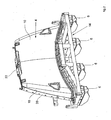
- the molding tool according to the invention essentially consists of a die 2 and a temple 4, which in the view according to FIG. 1 the sake of clarity is shown rotated by 90 ° about its vertical axis.
- the die 2 and the punch 4 limit in the closed state of the molding tool (hereinafter referred to as tool), not shown, a cavity which corresponds to the shape of the wind deflector.
- the tool is executed standing, the punch 4 is attached via four brackets 6 on a punch spar of the pressing device and movable in the vertical direction to open the tool or close.
- Both the punch 4 and the die 2 essentially consist of a comparatively thin-walled cast shell, hereinafter referred to as die shell 2 and punch shell 10, which are each received and supported in a support frame 12 and 14, respectively.
- the brackets 6 are attached to the support frame 14, so that the punch 4 is attached hanging on said punch spar.
- These support frames 12, 14 are designed such that they absorb the forces resulting from the pressing process and the high internal mold pressure associated therewith and support the shells 8, 10 in such a way that the desired molded part quality can be achieved.
- the punch 4 is rotated by 180 °, so to speak turned upside down, so that the brackets 6 point downwards. You can see the cavity of the tool limiting punch cup 10, which is formed according to the Windabweisergeometrie.
- the parting plane between punch 4 and die 2 is determined by the circumferential, step-shaped protruding edge 16 of the mold, which with a correspondingly shaped end wall 18 (see FIG. 1 ) cooperates with the die shell 8 to seal the cavity.
- the shell edge 20 which adjoins the peripheral edge of the mold 16 also serves for fastening the stamping shell 10 to the support frame 14 FIG. 2
- an attachment (sprue) 22 is formed, via which the resin is injected into the cavity.
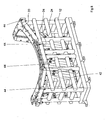
- FIG. 3 shows the punch 4 according to FIG. 2 from the rear, wherein the support is visible through the support frame 14. This forms a backbone over which the forces acting on the punch cup 10 forces can be absorbed.
- the support of the punch cup 10 via a plurality of support bolts 24 which are anchored in struts of the support frame 14 and in particular along the shell edge 20 and also from the inside of the tool cavity remote from the large area (visible in FIG FIG. 3 ) of the stamp cup 10 attack.
- the support bolts 24 pass through at least in the region of the shell edge 20, the wall of the punch cup 10th
- spacer elements 26 are further formed, which determine and prevent the relative position between Matize 2 and punch 4 in the closed state of the tool that the punch 4 dips too deep into the die 2.
- These spacer elements 26 are designed to be adjustable, so that tolerance of process tolerances in the molded part wall thickness can be compensated for by process parameters.
- Relative positioning and locking of die 2 and punch 4 is further accomplished by guides / latches 28 connected to respective guide members 30 (see FIG FIG. 1 ) of the die cooperate to position and lock them together.
- FIG. 3 can be removed that the shell edge 20 is formed in the console-side region 6 to a laterally projecting support edge 31, via which the punch 4 is attached to the console-side region of the support frame 4.
- the production of the punch cup 10 is carried out according to a conventional Stahlg intelligent Kunststoffmaschinen, for example, milled sand cores or an Exporitmodell and a core molding process can be used to create the mold.
- a conventional Stahlg intelligent Kunststoffmaschinen for example, milled sand cores or an Exporitmodell and a core molding process can be used to create the mold.
- FIG. 4 shows a sectional view from the left on the punch 4 according to FIG. 2 ,
- this section is designed with a comparatively large wall thickness.
- this wall thickness is of course designed according to the expected in-mold pressure, in the wind deflector shown, the wall thickness after casting is about 35mm.
- a machining allowance of about 10mm is taken into account - this measurement layer is in FIG. 4 designated by the reference numeral 32. She is so measured that there is enough machining allowance for a superfinishing operation following the casting in order to form the tool cavity with the desired geometry and surface quality.
- This superfine machining can be carried out, for example, by polishing or milled the stamped shell surface.
- a wall thickness of, for example, 25 mm in the region delimiting the cavity
- the stamping shell 10 is formed with Temper michskanälen via which the tool can be cooled or heated depending on the process step.
- Temperiansskanäle can be formed in different ways, in each case, already taken when pouring the shells 8, 10 appropriate precautions. This is based on the FIGS. 5 and 6 explains the different versions of the detail D in FIG. 4 demonstrate.
- bead-shaped projections 36 are formed in the region of Temperiansskanäle. After the casting process, milling grooves extending along the bead-shaped projections 36 are formed, into which tubes (40), for example of stainless steel or copper, are inserted, which then form the tempering passages or passages 34. These extend over the back of the punch cup 10th
- the effort for the subsequent milling and inserting the tubes 40 shy they can already be poured during the casting process.
- This embodiment is in FIG. 6 indicated.
- the high temperature resistant tubes must be introduced into the cast steel mold as an insert. Due to the relatively high melting temperature of the tool steel, these pipes are preferably made of ceramic. After the steel casting, the temperature control channels 34 are already formed, so that only the connection areas for the cooling / heating medium connection must be processed.
- FIG. 7 shows a single representation of the die 2 FIG. 1 and FIG. 8 a back view of this die 2. Its basic structure is substantially the same as the punch 4, so that only the essential elements are described to avoid repetition.
- the die 2 in turn consists of a die cast 8 made of cast steel, whose in FIG. 7 the region facing the viewer limits the cavity and whose region arranged outside the cavity is in turn designed as a shell edge 20 with the end wall 18 located in the parting plane.
- the forces occurring during pressing are absorbed by the support frame 12, which supports the Matizenschale 8 via a plurality of support bolts 24.
- the support pins 24 arranged in the region of the rear side of the cavity are fastened to support projections 42 projecting on the back, so that the wall does not have to be penetrated in the region of the cavity.
- the engaging at the edge of the shell 20 support pin 24 enforce the shell wall.
- a plurality of spacer blocks 44 are formed, which limit the maximum lowering position in cooperation with the spacer elements 26 of the punch 4.
- the support frame 12 further still carries Guide elements 30 (see FIG. 7 ), which cooperate with the guides 28 of the punch 4 to set and lock the relative position between the die 2 and punch 4.
- FIG. 9 shows a sectional side view from the left as shown in FIG. 7 , It can be seen that the die shell 8 is provided with an outer layer 32 which enables polishing or milling of the die shell 8. This oversize layer is again about 10mm, so that after this superfine the wall thickness in the region of the cavity is about 25mm. However, this wall thickness may vary depending on the molding geometry and the required in-mold pressure. Also, the die shell 8 is provided with one or more Temper michskanälen, according to the FIGS. 10 and 11 can be executed. According to the embodiment FIG. 10 bead-shaped projections 36 are again formed on the back of the die shell 8 along the temperature control channels 37 provided, which are provided with millings 38 after the steel casting process, into which tubes 40 are inserted to form the tempering channels 34.
- FIG. 11 are made of high temperature resistant material tubes 40 used as inserts into the steel mold, so that after the casting process, the tubes 40 are integrated in the region of the bead-shaped projections 36 and only minimal reworking in the connection area are required.
- the mold is formed of cast shells with respective supporting structures. These comparatively thin-walled shells can be produced very easily in the casting process, so that the procedural expense is minimal.
- a molding tool for producing plastic composite components with a tool cavity limiting die and a stamp.
- the die and the punch are formed essentially from a thin-walled shell produced in a casting process, which is supported in each case in a supporting structure.
Landscapes
- Engineering & Computer Science (AREA)
- Mechanical Engineering (AREA)
- Manufacturing & Machinery (AREA)
- Mounting, Exchange, And Manufacturing Of Dies (AREA)
- Moulds For Moulding Plastics Or The Like (AREA)
Claims (8)
- Outil de formage servant à fabriquer des éléments composites en plastique, comprenant une matrice (2) délimitant une cavité d'outil et un poinçon (4), sachant que la matrice (2) et le poinçon (4) sont respectivement réalisés à partir d'une coquille (8, 10) à paroi mince fabriquée lors d'un procédé de coulée, sachant que les coquilles (8, 10) sont en appui respectivement dans une structure porteuse, caractérisé en ce que le support du poinçon (4) et de la matrice (2) se fait grâce aux cadres porteurs (12, 14) par l'intermédiaire d'une pluralité de boulons de soutien (24), sachant que dans le cas du poinçon (4), les boulons de soutien (24) sont ancrés dans des montants du cadre porteur (14), et que dans le cas de la matrice (2), les boulons de soutien (24) disposés dans la zone du côté arrière de la cavité sont fixés au niveau de parties de soutien faisant saillie (42) côté arrière.
- Outil de formage selon la revendication 1, sachant que les grandes surfaces délimitant la cavité des coques coulées (8, 10) sont soumises à une finition de haute précision par polissage et/ou par fraisage, sachant qu'est prévue, aux fins de la finition de haute précision, une surépaisseur, qui est prise en compte lors de l'opération de coulée.
- Outil de formage selon la revendication 1 ou 2, sachant que le matériau de coulée est un acier pour outil.
- Outil de formage selon l'une quelconque des revendications précédentes, sachant que l'épaisseur de paroi des coques coulées (8, 10) est inférieure à 50 mm, de préférence inférieure ou égale à 35 mm.
- Outil de formage selon la revendication 2, sachant que la surépaisseur est inférieure ou égale à 15 mm, de préférence est d'environ 10 mm.
- Outil de formage selon l'une quelconque des revendications précédentes, sachant que des canaux de régulation de la température (34) sont réalisés dans ou au niveau de la coquille coulée (8, 10).
- Outil de formage selon la revendication 6, sachant que les canaux de régulation de la température (34) sont réalisés par des tubes (40), qui sont insérés ultérieurement dans la coquille coulée (8, 10) ou sont mis en place lors de la coulée.
- Outil de formage selon la revendication 7, dernière variante, sachant que les tubes (40) sont réalisés sous la forme de pièces en céramique à insérer.
Applications Claiming Priority (2)
| Application Number | Priority Date | Filing Date | Title |
|---|---|---|---|
| DE102006003934 | 2006-01-26 | ||
| DE102006004906.3A DE102006004906B4 (de) | 2006-01-26 | 2006-02-01 | Formwerkzeug |
Publications (3)
| Publication Number | Publication Date |
|---|---|
| EP1813404A2 EP1813404A2 (fr) | 2007-08-01 |
| EP1813404A3 EP1813404A3 (fr) | 2008-05-07 |
| EP1813404B1 true EP1813404B1 (fr) | 2013-12-25 |
Family
ID=38042532
Family Applications (1)
| Application Number | Title | Priority Date | Filing Date |
|---|---|---|---|
| EP07001643.1A Not-in-force EP1813404B1 (fr) | 2006-01-26 | 2007-01-25 | Outil de formage |
Country Status (2)
| Country | Link |
|---|---|
| EP (1) | EP1813404B1 (fr) |
| DE (1) | DE102006004906B4 (fr) |
Families Citing this family (9)
| Publication number | Priority date | Publication date | Assignee | Title |
|---|---|---|---|---|
| US8691137B2 (en) * | 2009-03-04 | 2014-04-08 | The Boeing Company | Method of molding partus using a tool sleeve for mold die |
| US9102103B2 (en) | 2006-02-02 | 2015-08-11 | The Boeing Company | Thermoplastic composite parts having integrated metal fittings and method of making the same |
| US8491745B2 (en) | 2007-02-03 | 2013-07-23 | The Boeing Company | Method and material efficient tooling for continuous compression molding |
| US10449736B2 (en) | 2006-02-02 | 2019-10-22 | The Boeing Company | Apparatus for fabricating thermoplastic composite parts |
| US8333858B2 (en) | 2006-02-02 | 2012-12-18 | The Boeing Company | Method for fabricating curved thermoplastic composite parts |
| US7807005B2 (en) | 2006-02-02 | 2010-10-05 | The Boeing Company | Fabrication process for thermoplastic composite parts |
| US10232532B1 (en) | 2006-02-02 | 2019-03-19 | The Boeing Company | Method for fabricating tapered thermoplastic composite parts |
| US10821653B2 (en) | 2010-02-24 | 2020-11-03 | Alexander M. Rubin | Continuous molding of thermoplastic laminates |
| US11390013B2 (en) | 2017-11-21 | 2022-07-19 | General Electric Company | Vacuum forming mold assembly and associated methods |
Citations (3)
| Publication number | Priority date | Publication date | Assignee | Title |
|---|---|---|---|---|
| DE10159456A1 (de) * | 2000-12-05 | 2002-06-13 | L & S Praez Sgus Gmbh | Werkzeuge bzw. Werkzeugeinsätze für abformende Fertigungsverfahren der Kunststoffverarbeitung und Gießereitechnik und Verfahren zu ihrer Herstellung |
| EP1318002A1 (fr) * | 2001-12-06 | 2003-06-11 | The Boeing Company | Dispositif de mise en forme utilisant une chauffage à induction, contenant un moule ceramique avec une couche durable |
| JP2005329555A (ja) * | 2004-05-18 | 2005-12-02 | Mitsubishi Heavy Ind Ltd | 成形用金型 |
Family Cites Families (4)
| Publication number | Priority date | Publication date | Assignee | Title |
|---|---|---|---|---|
| JPS57157708A (en) * | 1981-03-24 | 1982-09-29 | Honda Motor Co Ltd | Mold for molding synthetic resin on small scale |
| JPS62292410A (ja) * | 1986-06-13 | 1987-12-19 | Janome Sewing Mach Co Ltd | 合成樹脂成形用の型 |
| US5744173A (en) * | 1996-02-27 | 1998-04-28 | Aeroquip Corporation | Mold inserts for injection moldings |
| JP2003094443A (ja) * | 2001-07-16 | 2003-04-03 | Tokai Model:Kk | 成形型及びその製法 |
-
2006
- 2006-02-01 DE DE102006004906.3A patent/DE102006004906B4/de not_active Expired - Fee Related
-
2007
- 2007-01-25 EP EP07001643.1A patent/EP1813404B1/fr not_active Not-in-force
Patent Citations (3)
| Publication number | Priority date | Publication date | Assignee | Title |
|---|---|---|---|---|
| DE10159456A1 (de) * | 2000-12-05 | 2002-06-13 | L & S Praez Sgus Gmbh | Werkzeuge bzw. Werkzeugeinsätze für abformende Fertigungsverfahren der Kunststoffverarbeitung und Gießereitechnik und Verfahren zu ihrer Herstellung |
| EP1318002A1 (fr) * | 2001-12-06 | 2003-06-11 | The Boeing Company | Dispositif de mise en forme utilisant une chauffage à induction, contenant un moule ceramique avec une couche durable |
| JP2005329555A (ja) * | 2004-05-18 | 2005-12-02 | Mitsubishi Heavy Ind Ltd | 成形用金型 |
Also Published As
| Publication number | Publication date |
|---|---|
| DE102006004906B4 (de) | 2014-11-06 |
| EP1813404A3 (fr) | 2008-05-07 |
| DE102006004906A1 (de) | 2007-08-09 |
| EP1813404A2 (fr) | 2007-08-01 |
Similar Documents
| Publication | Publication Date | Title |
|---|---|---|
| EP1813404B1 (fr) | Outil de formage | |
| EP2286974B1 (fr) | Dispositif de formage et procédé d'enlèvement d'un objet | |
| EP2988913B1 (fr) | Moule permettant de fabriquer un élément composite, pourvu d'au moins un trou de ventilation dans lequel est disposée une tige d'éjection | |
| EP3186057B1 (fr) | Procédé et dispositif de fabrication de pièces | |
| DE102008012230A1 (de) | Modulares Werkzeug | |
| EP3386707B1 (fr) | Procédé de fabrication d'un tableau de bord pour un véhicule automobile | |
| EP3393753B1 (fr) | Télécommande monolithique | |
| EP2100678B1 (fr) | Outil de coulée sous pression d'une machine de coulée sous pression | |
| DE102005011311B3 (de) | Schieberrückzug einer Spritzgießform und Verfahren zum Herstellen eines Spritzgießteils | |
| EP1737639B1 (fr) | Dispositif pour fabriquer des elements moules et unite modulaire pour un dispositif de ce type | |
| EP2623233B1 (fr) | Procédé de fabrication de pièces creuses coulées sous pression en aluminium | |
| DE102007002298B4 (de) | Vorrichtung und Verfahren zur Herstellung eines Formteils | |
| EP3482905B1 (fr) | Moule ainsi que procédé de moulage d'un composant | |
| EP3727723A1 (fr) | Procédé de production d'une partie de moule ainsi qu'insert d'alimentation destiné à être utilisé dans un tel procédé | |
| AT525769A1 (de) | Schließeinheit für eine Formgebungsmaschine | |
| EP2134528B1 (fr) | Moule avec cadre, à structure modulaire | |
| DE102011057033A1 (de) | Presswerkzeug und Formteil | |
| EP0700766B1 (fr) | Dispositif pour fabriquer des articles moulés par injection | |
| EP1541320B1 (fr) | Appareil pour thermo formage un réservoir en matière plastique | |
| DE102008016118A1 (de) | Vorrichtung und Verfahren zur Herstellung von Formbauteilen in Fertigungsverfahren | |
| EP2602049B1 (fr) | Outils de construction hybride | |
| EP2452796B1 (fr) | Moitié d'outil pour un outil de formage et son procédé de fabrication | |
| EP1017522B1 (fr) | Outil notamment destine a la fabrication de noyaux | |
| EP3808528B1 (fr) | Procédé de fabrication d'un élément d'appui revêtu à partir d'élastomère | |
| EP2511087A2 (fr) | Procédé de fabrication d'une pièce usinée |
Legal Events
| Date | Code | Title | Description |
|---|---|---|---|
| PUAI | Public reference made under article 153(3) epc to a published international application that has entered the european phase |
Free format text: ORIGINAL CODE: 0009012 |
|
| 17P | Request for examination filed |
Effective date: 20070125 |
|
| AK | Designated contracting states |
Kind code of ref document: A2 Designated state(s): AT BE BG CH CY CZ DE DK EE ES FI FR GB GR HU IE IS IT LI LT LU LV MC NL PL PT RO SE SI SK TR |
|
| AX | Request for extension of the european patent |
Extension state: AL BA HR MK YU |
|
| PUAL | Search report despatched |
Free format text: ORIGINAL CODE: 0009013 |
|
| AK | Designated contracting states |
Kind code of ref document: A3 Designated state(s): AT BE BG CH CY CZ DE DK EE ES FI FR GB GR HU IE IS IT LI LT LU LV MC NL PL PT RO SE SI SK TR |
|
| AX | Request for extension of the european patent |
Extension state: AL BA HR MK RS |
|
| AKX | Designation fees paid |
Designated state(s): AT BE BG CH CY CZ DE DK EE ES FI FR GB GR HU IE IS IT LI LT LU LV MC NL PL PT RO SE SI SK TR |
|
| 17Q | First examination report despatched |
Effective date: 20100813 |
|
| GRAP | Despatch of communication of intention to grant a patent |
Free format text: ORIGINAL CODE: EPIDOSNIGR1 |
|
| INTG | Intention to grant announced |
Effective date: 20130712 |
|
| GRAS | Grant fee paid |
Free format text: ORIGINAL CODE: EPIDOSNIGR3 |
|
| GRAA | (expected) grant |
Free format text: ORIGINAL CODE: 0009210 |
|
| AK | Designated contracting states |
Kind code of ref document: B1 Designated state(s): AT BE BG CH CY CZ DE DK EE ES FI FR GB GR HU IE IS IT LI LT LU LV MC NL PL PT RO SE SI SK TR |
|
| REG | Reference to a national code |
Ref country code: GB Ref legal event code: FG4D Free format text: NOT ENGLISH |
|
| REG | Reference to a national code |
Ref country code: CH Ref legal event code: EP |
|
| REG | Reference to a national code |
Ref country code: AT Ref legal event code: REF Ref document number: 646363 Country of ref document: AT Kind code of ref document: T Effective date: 20140115 |
|
| REG | Reference to a national code |
Ref country code: IE Ref legal event code: FG4D Free format text: LANGUAGE OF EP DOCUMENT: GERMAN |
|
| REG | Reference to a national code |
Ref country code: DE Ref legal event code: R096 Ref document number: 502007012618 Country of ref document: DE Effective date: 20140213 |
|
| PG25 | Lapsed in a contracting state [announced via postgrant information from national office to epo] |
Ref country code: SE Free format text: LAPSE BECAUSE OF FAILURE TO SUBMIT A TRANSLATION OF THE DESCRIPTION OR TO PAY THE FEE WITHIN THE PRESCRIBED TIME-LIMIT Effective date: 20131225 Ref country code: LT Free format text: LAPSE BECAUSE OF FAILURE TO SUBMIT A TRANSLATION OF THE DESCRIPTION OR TO PAY THE FEE WITHIN THE PRESCRIBED TIME-LIMIT Effective date: 20131225 Ref country code: FI Free format text: LAPSE BECAUSE OF FAILURE TO SUBMIT A TRANSLATION OF THE DESCRIPTION OR TO PAY THE FEE WITHIN THE PRESCRIBED TIME-LIMIT Effective date: 20131225 |
|
| REG | Reference to a national code |
Ref country code: NL Ref legal event code: VDEP Effective date: 20131225 |
|
| REG | Reference to a national code |
Ref country code: LT Ref legal event code: MG4D |
|
| PG25 | Lapsed in a contracting state [announced via postgrant information from national office to epo] |
Ref country code: LV Free format text: LAPSE BECAUSE OF FAILURE TO SUBMIT A TRANSLATION OF THE DESCRIPTION OR TO PAY THE FEE WITHIN THE PRESCRIBED TIME-LIMIT Effective date: 20131225 |
|
| BERE | Be: lapsed |
Owner name: GEORG FRITZMEIER G.M.B.H. + CO. KG Effective date: 20140131 |
|
| PG25 | Lapsed in a contracting state [announced via postgrant information from national office to epo] |
Ref country code: IS Free format text: LAPSE BECAUSE OF FAILURE TO SUBMIT A TRANSLATION OF THE DESCRIPTION OR TO PAY THE FEE WITHIN THE PRESCRIBED TIME-LIMIT Effective date: 20140425 Ref country code: EE Free format text: LAPSE BECAUSE OF FAILURE TO SUBMIT A TRANSLATION OF THE DESCRIPTION OR TO PAY THE FEE WITHIN THE PRESCRIBED TIME-LIMIT Effective date: 20131225 |
|
| PG25 | Lapsed in a contracting state [announced via postgrant information from national office to epo] |
Ref country code: NL Free format text: LAPSE BECAUSE OF FAILURE TO SUBMIT A TRANSLATION OF THE DESCRIPTION OR TO PAY THE FEE WITHIN THE PRESCRIBED TIME-LIMIT Effective date: 20131225 Ref country code: CZ Free format text: LAPSE BECAUSE OF FAILURE TO SUBMIT A TRANSLATION OF THE DESCRIPTION OR TO PAY THE FEE WITHIN THE PRESCRIBED TIME-LIMIT Effective date: 20131225 Ref country code: PL Free format text: LAPSE BECAUSE OF FAILURE TO SUBMIT A TRANSLATION OF THE DESCRIPTION OR TO PAY THE FEE WITHIN THE PRESCRIBED TIME-LIMIT Effective date: 20131225 Ref country code: ES Free format text: LAPSE BECAUSE OF FAILURE TO SUBMIT A TRANSLATION OF THE DESCRIPTION OR TO PAY THE FEE WITHIN THE PRESCRIBED TIME-LIMIT Effective date: 20131225 Ref country code: SK Free format text: LAPSE BECAUSE OF FAILURE TO SUBMIT A TRANSLATION OF THE DESCRIPTION OR TO PAY THE FEE WITHIN THE PRESCRIBED TIME-LIMIT Effective date: 20131225 Ref country code: PT Free format text: LAPSE BECAUSE OF FAILURE TO SUBMIT A TRANSLATION OF THE DESCRIPTION OR TO PAY THE FEE WITHIN THE PRESCRIBED TIME-LIMIT Effective date: 20140428 Ref country code: LU Free format text: LAPSE BECAUSE OF FAILURE TO SUBMIT A TRANSLATION OF THE DESCRIPTION OR TO PAY THE FEE WITHIN THE PRESCRIBED TIME-LIMIT Effective date: 20140125 Ref country code: RO Free format text: LAPSE BECAUSE OF FAILURE TO SUBMIT A TRANSLATION OF THE DESCRIPTION OR TO PAY THE FEE WITHIN THE PRESCRIBED TIME-LIMIT Effective date: 20131225 Ref country code: CY Free format text: LAPSE BECAUSE OF FAILURE TO SUBMIT A TRANSLATION OF THE DESCRIPTION OR TO PAY THE FEE WITHIN THE PRESCRIBED TIME-LIMIT Effective date: 20131225 |
|
| REG | Reference to a national code |
Ref country code: CH Ref legal event code: PL |
|
| REG | Reference to a national code |
Ref country code: DE Ref legal event code: R097 Ref document number: 502007012618 Country of ref document: DE |
|
| PG25 | Lapsed in a contracting state [announced via postgrant information from national office to epo] |
Ref country code: MC Free format text: LAPSE BECAUSE OF FAILURE TO SUBMIT A TRANSLATION OF THE DESCRIPTION OR TO PAY THE FEE WITHIN THE PRESCRIBED TIME-LIMIT Effective date: 20131225 |
|
| PG25 | Lapsed in a contracting state [announced via postgrant information from national office to epo] |
Ref country code: LI Free format text: LAPSE BECAUSE OF NON-PAYMENT OF DUE FEES Effective date: 20140131 Ref country code: DK Free format text: LAPSE BECAUSE OF FAILURE TO SUBMIT A TRANSLATION OF THE DESCRIPTION OR TO PAY THE FEE WITHIN THE PRESCRIBED TIME-LIMIT Effective date: 20131225 Ref country code: CH Free format text: LAPSE BECAUSE OF NON-PAYMENT OF DUE FEES Effective date: 20140131 |
|
| PLBE | No opposition filed within time limit |
Free format text: ORIGINAL CODE: 0009261 |
|
| STAA | Information on the status of an ep patent application or granted ep patent |
Free format text: STATUS: NO OPPOSITION FILED WITHIN TIME LIMIT |
|
| REG | Reference to a national code |
Ref country code: IE Ref legal event code: MM4A |
|
| 26N | No opposition filed |
Effective date: 20140926 |
|
| REG | Reference to a national code |
Ref country code: DE Ref legal event code: R097 Ref document number: 502007012618 Country of ref document: DE Effective date: 20140926 |
|
| REG | Reference to a national code |
Ref country code: FR Ref legal event code: PLFP Year of fee payment: 9 |
|
| PG25 | Lapsed in a contracting state [announced via postgrant information from national office to epo] |
Ref country code: IE Free format text: LAPSE BECAUSE OF NON-PAYMENT OF DUE FEES Effective date: 20140125 Ref country code: BE Free format text: LAPSE BECAUSE OF NON-PAYMENT OF DUE FEES Effective date: 20140131 |
|
| REG | Reference to a national code |
Ref country code: AT Ref legal event code: MM01 Ref document number: 646363 Country of ref document: AT Kind code of ref document: T Effective date: 20140125 |
|
| PG25 | Lapsed in a contracting state [announced via postgrant information from national office to epo] |
Ref country code: SI Free format text: LAPSE BECAUSE OF FAILURE TO SUBMIT A TRANSLATION OF THE DESCRIPTION OR TO PAY THE FEE WITHIN THE PRESCRIBED TIME-LIMIT Effective date: 20131225 Ref country code: AT Free format text: LAPSE BECAUSE OF NON-PAYMENT OF DUE FEES Effective date: 20140125 |
|
| REG | Reference to a national code |
Ref country code: FR Ref legal event code: PLFP Year of fee payment: 10 |
|
| PG25 | Lapsed in a contracting state [announced via postgrant information from national office to epo] |
Ref country code: BG Free format text: LAPSE BECAUSE OF FAILURE TO SUBMIT A TRANSLATION OF THE DESCRIPTION OR TO PAY THE FEE WITHIN THE PRESCRIBED TIME-LIMIT Effective date: 20131225 |
|
| PG25 | Lapsed in a contracting state [announced via postgrant information from national office to epo] |
Ref country code: GR Free format text: LAPSE BECAUSE OF FAILURE TO SUBMIT A TRANSLATION OF THE DESCRIPTION OR TO PAY THE FEE WITHIN THE PRESCRIBED TIME-LIMIT Effective date: 20140326 |
|
| PG25 | Lapsed in a contracting state [announced via postgrant information from national office to epo] |
Ref country code: TR Free format text: LAPSE BECAUSE OF FAILURE TO SUBMIT A TRANSLATION OF THE DESCRIPTION OR TO PAY THE FEE WITHIN THE PRESCRIBED TIME-LIMIT Effective date: 20131225 Ref country code: HU Free format text: LAPSE BECAUSE OF FAILURE TO SUBMIT A TRANSLATION OF THE DESCRIPTION OR TO PAY THE FEE WITHIN THE PRESCRIBED TIME-LIMIT; INVALID AB INITIO Effective date: 20070125 |
|
| REG | Reference to a national code |
Ref country code: FR Ref legal event code: PLFP Year of fee payment: 11 |
|
| REG | Reference to a national code |
Ref country code: FR Ref legal event code: PLFP Year of fee payment: 12 |
|
| PGFP | Annual fee paid to national office [announced via postgrant information from national office to epo] |
Ref country code: GB Payment date: 20220125 Year of fee payment: 16 Ref country code: DE Payment date: 20220111 Year of fee payment: 16 |
|
| PGFP | Annual fee paid to national office [announced via postgrant information from national office to epo] |
Ref country code: IT Payment date: 20220124 Year of fee payment: 16 Ref country code: FR Payment date: 20220120 Year of fee payment: 16 |
|
| REG | Reference to a national code |
Ref country code: DE Ref legal event code: R119 Ref document number: 502007012618 Country of ref document: DE |
|
| GBPC | Gb: european patent ceased through non-payment of renewal fee |
Effective date: 20230125 |
|
| PG25 | Lapsed in a contracting state [announced via postgrant information from national office to epo] |
Ref country code: GB Free format text: LAPSE BECAUSE OF NON-PAYMENT OF DUE FEES Effective date: 20230125 Ref country code: DE Free format text: LAPSE BECAUSE OF NON-PAYMENT OF DUE FEES Effective date: 20230801 |
|
| PG25 | Lapsed in a contracting state [announced via postgrant information from national office to epo] |
Ref country code: FR Free format text: LAPSE BECAUSE OF NON-PAYMENT OF DUE FEES Effective date: 20230131 |
|
| PG25 | Lapsed in a contracting state [announced via postgrant information from national office to epo] |
Ref country code: IT Free format text: LAPSE BECAUSE OF NON-PAYMENT OF DUE FEES Effective date: 20230125 |